EP2515525A2 - Image pickup apparatus and control method thereof - Google Patents
Image pickup apparatus and control method thereof Download PDFInfo
- Publication number
- EP2515525A2 EP2515525A2 EP12164899A EP12164899A EP2515525A2 EP 2515525 A2 EP2515525 A2 EP 2515525A2 EP 12164899 A EP12164899 A EP 12164899A EP 12164899 A EP12164899 A EP 12164899A EP 2515525 A2 EP2515525 A2 EP 2515525A2
- Authority
- EP
- European Patent Office
- Prior art keywords
- focus
- movement amount
- image
- image pickup
- lens
- Prior art date
- Legal status (The legal status is an assumption and is not a legal conclusion. Google has not performed a legal analysis and makes no representation as to the accuracy of the status listed.)
- Withdrawn
Links
- 238000000034 method Methods 0.000 title claims description 12
- 238000001514 detection method Methods 0.000 claims abstract description 71
- 230000003287 optical effect Effects 0.000 claims abstract description 52
- 230000004044 response Effects 0.000 claims abstract description 20
- 230000008859 change Effects 0.000 claims abstract description 11
- 238000012937 correction Methods 0.000 claims description 34
- 238000002620 method output Methods 0.000 claims 2
- 238000011156 evaluation Methods 0.000 description 14
- 239000004973 liquid crystal related substance Substances 0.000 description 13
- 230000000875 corresponding effect Effects 0.000 description 10
- 230000011514 reflex Effects 0.000 description 8
- 230000008569 process Effects 0.000 description 7
- 230000006870 function Effects 0.000 description 5
- 230000006866 deterioration Effects 0.000 description 4
- 238000005375 photometry Methods 0.000 description 4
- 238000009825 accumulation Methods 0.000 description 3
- 230000014509 gene expression Effects 0.000 description 3
- 238000004364 calculation method Methods 0.000 description 2
- 238000006243 chemical reaction Methods 0.000 description 2
- 230000006835 compression Effects 0.000 description 2
- 238000007906 compression Methods 0.000 description 2
- 238000004590 computer program Methods 0.000 description 2
- 230000006837 decompression Effects 0.000 description 2
- 230000007774 longterm Effects 0.000 description 2
- 238000012360 testing method Methods 0.000 description 2
- 230000002159 abnormal effect Effects 0.000 description 1
- 230000005856 abnormality Effects 0.000 description 1
- 239000000470 constituent Substances 0.000 description 1
- 230000002596 correlated effect Effects 0.000 description 1
- 238000010586 diagram Methods 0.000 description 1
- 238000012986 modification Methods 0.000 description 1
- 230000004048 modification Effects 0.000 description 1
- 238000002360 preparation method Methods 0.000 description 1
- 230000002787 reinforcement Effects 0.000 description 1
- 238000005070 sampling Methods 0.000 description 1
- 230000035945 sensitivity Effects 0.000 description 1
- 238000000926 separation method Methods 0.000 description 1
Images


Classifications
-
- G—PHYSICS
- G02—OPTICS
- G02B—OPTICAL ELEMENTS, SYSTEMS OR APPARATUS
- G02B7/00—Mountings, adjusting means, or light-tight connections, for optical elements
- G02B7/28—Systems for automatic generation of focusing signals
- G02B7/285—Systems for automatic generation of focusing signals including two or more different focus detection devices, e.g. both an active and a passive focus detecting device
-
- H—ELECTRICITY
- H04—ELECTRIC COMMUNICATION TECHNIQUE
- H04N—PICTORIAL COMMUNICATION, e.g. TELEVISION
- H04N23/00—Cameras or camera modules comprising electronic image sensors; Control thereof
- H04N23/60—Control of cameras or camera modules
- H04N23/67—Focus control based on electronic image sensor signals
- H04N23/672—Focus control based on electronic image sensor signals based on the phase difference signals
-
- G—PHYSICS
- G02—OPTICS
- G02B—OPTICAL ELEMENTS, SYSTEMS OR APPARATUS
- G02B7/00—Mountings, adjusting means, or light-tight connections, for optical elements
- G02B7/28—Systems for automatic generation of focusing signals
- G02B7/34—Systems for automatic generation of focusing signals using different areas in a pupil plane
-
- G—PHYSICS
- G02—OPTICS
- G02B—OPTICAL ELEMENTS, SYSTEMS OR APPARATUS
- G02B7/00—Mountings, adjusting means, or light-tight connections, for optical elements
- G02B7/28—Systems for automatic generation of focusing signals
- G02B7/36—Systems for automatic generation of focusing signals using image sharpness techniques, e.g. image processing techniques for generating autofocus signals
-
- H—ELECTRICITY
- H04—ELECTRIC COMMUNICATION TECHNIQUE
- H04N—PICTORIAL COMMUNICATION, e.g. TELEVISION
- H04N23/00—Cameras or camera modules comprising electronic image sensors; Control thereof
- H04N23/60—Control of cameras or camera modules
- H04N23/67—Focus control based on electronic image sensor signals
- H04N23/673—Focus control based on electronic image sensor signals based on contrast or high frequency components of image signals, e.g. hill climbing method
-
- G—PHYSICS
- G03—PHOTOGRAPHY; CINEMATOGRAPHY; ANALOGOUS TECHNIQUES USING WAVES OTHER THAN OPTICAL WAVES; ELECTROGRAPHY; HOLOGRAPHY
- G03B—APPARATUS OR ARRANGEMENTS FOR TAKING PHOTOGRAPHS OR FOR PROJECTING OR VIEWING THEM; APPARATUS OR ARRANGEMENTS EMPLOYING ANALOGOUS TECHNIQUES USING WAVES OTHER THAN OPTICAL WAVES; ACCESSORIES THEREFOR
- G03B13/00—Viewfinders; Focusing aids for cameras; Means for focusing for cameras; Autofocus systems for cameras
- G03B13/32—Means for focusing
- G03B13/34—Power focusing
- G03B13/36—Autofocus systems
-
- G—PHYSICS
- G03—PHOTOGRAPHY; CINEMATOGRAPHY; ANALOGOUS TECHNIQUES USING WAVES OTHER THAN OPTICAL WAVES; ELECTROGRAPHY; HOLOGRAPHY
- G03B—APPARATUS OR ARRANGEMENTS FOR TAKING PHOTOGRAPHS OR FOR PROJECTING OR VIEWING THEM; APPARATUS OR ARRANGEMENTS EMPLOYING ANALOGOUS TECHNIQUES USING WAVES OTHER THAN OPTICAL WAVES; ACCESSORIES THEREFOR
- G03B17/00—Details of cameras or camera bodies; Accessories therefor
- G03B17/02—Bodies
- G03B17/12—Bodies with means for supporting objectives, supplementary lenses, filters, masks, or turrets
- G03B17/14—Bodies with means for supporting objectives, supplementary lenses, filters, masks, or turrets interchangeably
-
- G—PHYSICS
- G03—PHOTOGRAPHY; CINEMATOGRAPHY; ANALOGOUS TECHNIQUES USING WAVES OTHER THAN OPTICAL WAVES; ELECTROGRAPHY; HOLOGRAPHY
- G03B—APPARATUS OR ARRANGEMENTS FOR TAKING PHOTOGRAPHS OR FOR PROJECTING OR VIEWING THEM; APPARATUS OR ARRANGEMENTS EMPLOYING ANALOGOUS TECHNIQUES USING WAVES OTHER THAN OPTICAL WAVES; ACCESSORIES THEREFOR
- G03B19/00—Cameras
- G03B19/02—Still-picture cameras
- G03B19/12—Reflex cameras with single objective and a movable reflector or a partly-transmitting mirror
-
- G—PHYSICS
- G03—PHOTOGRAPHY; CINEMATOGRAPHY; ANALOGOUS TECHNIQUES USING WAVES OTHER THAN OPTICAL WAVES; ELECTROGRAPHY; HOLOGRAPHY
- G03B—APPARATUS OR ARRANGEMENTS FOR TAKING PHOTOGRAPHS OR FOR PROJECTING OR VIEWING THEM; APPARATUS OR ARRANGEMENTS EMPLOYING ANALOGOUS TECHNIQUES USING WAVES OTHER THAN OPTICAL WAVES; ACCESSORIES THEREFOR
- G03B3/00—Focusing arrangements of general interest for cameras, projectors or printers
- G03B3/10—Power-operated focusing
Definitions
- the present invention relates to an image pickup apparatus capable of performing focus control by a phase difference detection method, and particularly to an image pickup apparatus having a focus calibration function of correcting an in-focus position obtained by the phase difference detection method, using an in-focus position detected by a contrast detection method.
- Lens-interchangeable image pickup apparatuses such as single-lens reflex cameras are often provided with a focus detection system using a phase difference detection method which detects, from a phase difference of paired object images formed by light passing through an image-pickup optical system of the interchangeable lens, a focus state (defocus amount) of the image-pickup optical system.
- the phase difference detection method involves a problem that influence of a light source, a color or a type of an object and the like makes it impossible to accurately detect an in-focus position.
- Japanese Patent Laid-Open No. 2003-295047 discloses a camera capable of solving such a problem, which has a function of performing focus calibration that corrects an in-focus position obtained by the phase difference detection method, using an in-focus position detected by a contrast detection method.
- the contrast detection method calculates a focus evaluation value showing contrast of an object from a video signal produced by using an image sensor of a digital camera, and decides the in-focus position that is a position of a focus lens where the focus evaluation value becomes maximum.
- the camera disclosed in Japanese Patent Laid-Open No. 2003-295047 monitors change of the focus evaluation value while performing minute drive (step-by-step drive) of the focus lens. This camera corrects, when performing image pickup, the in-focus position obtained by the phase difference detection method by using a correction amount obtained by the focus calibration, and then moves the focus lens to the corrected in-focus position to perform accurate focus control.
- Japanese Patent Laid-Open No. 2009-139728 discloses a camera that avoids, in a case where an abnormal determination is made in the in-focus position detection by the contrast detection method for the above-mentioned focus calibration, erroneous decision of the correction amount, by means of suspending the focus calibration or the like.
- the focus calibration disclosed in Japanese Patent Laid-Open Nos. 2003-295047 and 2009-139728 becomes effective on a condition that, in response to an instruction from the camera for the interchangeable lens to move the focus lens to the corrected in-focus position, the interchangeable lens can accurately move the focus lens to that corrected in-focus position.
- the interchangeable lens cannot always accurately move the focus lens to the instructed corrected in-focus position due to deterioration in its focus lens driving capability because of long-term use of the interchangeable lens or due to others.
- the present invention provides an image pickup apparatus capable of performing good focus calibration for interchangeable lenses (optical apparatuses) in various conditions or of various types and a control method thereof.
- the present invention in its first aspect provides an image pickup apparatus as specified in claims 1 to 6.
- the present invention in its second aspect provides a control method of an image pickup apparatus as specified in claim 7.
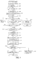
- FIG. 1 is a flowchart showing operations for focus calibration in a digital single-lens reflex camera that is Embodiment 1 of the present invention.
- FIG. 2 is a cross-sectional view showing a configuration of the digital single-lens reflex camera of Embodiment 1 in a mirror down state and a configuration of an interchangeable lens attached to the camera.
- FIG. 3 is a cross-sectional view showing a configuration of the digital single-lens reflex camera system of Embodiment 1 in a live-view state and the configuration of the interchangeable lens attached to the camera.
- FIG. 4 is a block diagram showing an electrical configuration of the digital single-lens reflex camera of Embodiment 1.
- FIG. 5 is a flowchart showing fundamental operations of the digital single-lens reflex camera of Embodiment 1.
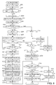
- FIG. 6 is a flowchart showing operations for focus calibration in a digital single-lens reflex camera that is Embodiment 2 of the present invention.
- FIGS. 2 and 3 show a configuration of a digital single-lens reflex (SLR) camera system including a digital SLR camera as an image pickup apparatus that is a first embodiment (Embodiment 1) of the present invention and an interchangeable lens as an optical apparatus.
- SLR digital single-lens reflex
- Reference numeral 1 denotes a main body of the digital SLR camera (hereinafter referred to as "a camera body”).
- Reference numeral 2 denotes a mount fixed to the camera body 1; the interchangeable lens 3 is detachably attached to the mount 2.
- the mount 2 is provided with an interface part (not shown) to communicate various signals with the interchangeable lens 3 and to supply power from the camera body 1 to the interchangeable lens 3.
- the interchangeable lens 3 houses thereinside an image-pickup optical system including a focus lens 3a, a magnification varying lens 3b and an aperture stop 17.
- FIGS. 2 and 3 show each lens as if it is constituted by a single lens, each lens may be constituted by plural lenses.
- reference numeral 4 denotes a main mirror constituted by a half mirror and rotatable between a down position shown in FIG. 2 and an up position shown in FIG. 3 .
- the main mirror 4 is rotated to the down position where the main mirror 4 is obliquely disposed in an image-pickup optical path as shown in FIG. 2 .
- the main mirror 4 disposed at the down position reflects light from the image-pickup optical system to introduce it to the viewfinder optical system.
- the viewfinder optical system includes a focusing plate on which the object image is formed by the light reflected by the main mirror 4 and a penta prism 10 that inverts the object image formed on the focusing plate 9.
- the viewfinder optical system further includes an eyepiece lens 11 that introduces the light from the penta prism 10 to an eye of a uses to cause the user to observe the object image formed on the focusing plate 9.
- image pickup and live-view display are performed (that is, in an image pickup/live-view observation state)
- the main mirror 4 is rotated to the up position where the main mirror 4 is retracted from the image-pickup optical path as shown in FIG. 3 , which allows the light from the image-pickup optical system to proceed toward a shutter 5 and an image sensor (image pickup element) 6 which are described later.
- the shutter 5 controls exposure of the image sensor 6, the exposure being made by the light from the image-pickup optical system.
- the shutter 5 in this embodiment is a focal-plane shutter that closes in the viewfinder observation state and opens in the image pickup/live-view observation state.
- the image sensor 6 is a photoelectric conversion element constituted by a CMOS sensor or a CCD sensor and photoelectrically converts the object image to output an image pickup signal.
- An image processor 44 (shown in FIG. 4 ) performs various image processes on the image pickup signal to produce an image signal.
- the image sensor 6 and the image processor 44 constitute an image pickup device.
- Reference numeral 7 denotes a sub mirror rotatable with the main mirror 4.
- the sub mirror 7 reflects light transmitted through the main mirror 4 located at the down position to introduce it to an AF unit 8 described later and is rotated to the up position with the main mirror 4 in the image pickup/live-view observation state.
- the AF unit 8 is constituted by a reflective mirror 8a, a secondary image-forming lens 8b and an area sensor 8c including plural light-receiving elements two-dimensionally arranged.
- the secondary image-forming lens 8b causes light entering thereinto from the image-pickup optical system and reflected by the main mirror 4, the sub mirror 7 and the reflective mirror 8a to form paired object images.
- the area sensor 8c photoelectrically converts the paired object images to produce paired image signals. These paired image signals are output to a focus detection circuit 26 shown in FIG. 4 and described later.
- the AF unit 8 thus configured enables detection of a focus state of the image-pickup optical system (that is, focus detection) by a phase difference detection method.
- the secondary image-forming lens 8b is configured to form paired object images of objects respectively included in plural areas of an image pickup frame. In other words, plural focus detection areas are disposed in the image pickup frame.
- Reference numeral 12 denotes a liquid crystal monitor that displays the image signals (live view images and captured images) and various information.
- reference numeral 13 denotes a focus motor that is a driving source to move the focus lens 3a in an optical axis direction.
- Reference numeral 14 denotes a lead screw that is rotated by the focus motor 13. The lead screw 14 engages with a rack 19 attached to the focus lens 3a (actually attached to a holding member holding the focus lens 3a). Therefore, rotation of the lead screw 14 by the focus motor 13 moves the rack 19 and the focus lens 3a in the optical axis direction by engagement of the lead screw 14 and the rack 19.
- a pulse plate 16 integrally rotatable with the lead screw 14 is attached to a tip of the lead screw 14.
- a photo coupler 15 including a light-emitting element and a light-receiving element that are arranged so as to sandwich part of the pulse plate 16 is disposed in the interchangeable lens 3.
- the photo coupler 15 produces a pulse signal in response to each reception of light from the light-emitting element at the light-receiving element with rotation of the pulse plate 16.
- This pulse signal is input to a focus controller 24 described later (shown in FIG. 4 ) that counts a number of the input pulse signals to detect a movement amount (or a position) of the focus lens 3a.
- Reference numeral 18 denotes an aperture stop driving part that includes an aperture stop driver 25 described later (shown in FIG. 4 ) and drives the aperture stop 17 in its opening and closing directions.
- FIG. 4 shows an electrical configuration of the above-described digital SLR camera system.
- Reference numeral 20 denotes a microcomputer (hereinafter referred to as "an MPU") serving as a main controller that controls operation of the camera body 1 and the entire camera system.
- Reference numeral 21 denotes a memory controller that controls operation of the image sensor 6 and performs control relating to image data.
- Reference numeral 22 denotes an EEPROM serving as a memory that stores data to be used for various control processes.
- Reference numeral 23 denotes a lens controller provided in the interchangeable lens 3.
- the lens controller 23 controls the focus controller 24 and the aperture stop driver 25 in the interchangeable lens 3 in response to control signals sent from the MPU 20 through the mount 2.
- the focus controller 24 receives information showing a target movement amount of the focus lens 3a from the lens controller 23 and the pulse signals (that is, information on an actual movement amount of the focus lens 3a) from the photo coupler 15.
- the focus controller 24 drives the focus motor 13 to move the focus lens 3a on the basis of the information on the target movement amount and the information on the actual movement amount.
- the aperture stop driver 25 drives the aperture stop 17 in response to an aperture stop drive signal from the lens controller 23.
- the focus detector 26 in the camera body 1 controls charge accumulation of the area sensor 8c provided in the AF unit 8 and charge reading therefrom, and outputs the paired image signals obtained in each of the focus detection areas to the MPU 20.
- the MPU 20 performs correlation calculation on the input paired image signals to calculate a phase difference therebetween.
- the MPU 20 calculates, from the phase difference, a defocus amount showing a focus state of the image-pickup optical system.
- the MPU 20 calculates an in-focus position of the focus lens 3a based on the calculated defocus amount and optical data (such as a focal length of the image-pickup optical system and a focus sensitivity of the focus lens 3a) received from the interchangeable lens 3 (lens controller 23).
- the in-focus position which is a first in-focus position, obtained by the phase difference detection method is hereinafter referred to as "a phase difference in-focus position".
- the MPU 20 sends information on the phase difference in-focus position to the lens controller 23.
- the AF unit 8, the focus detector 26 and the MPU 20 constitute a first detector.
- the lens controller 23 calculates the target movement amount of the focus lens 3a to move the focus lens 3a from a current position to the phase difference in-focus position, and then outputs information on the target movement amount to the focus controller 24.
- the focus controller 24 drives, according to the target movement amount, the focus motor 13 to move the focus lens 3a to the phase difference in-focus position, as described above.
- phase difference AF auto focus
- reference numeral 27 denotes a motor driver.
- the motor driver 27 controls a mirror motor (not shown) that drives the main mirror 4 and a charge motor (not shown) that charges the shutter 5.
- Reference numeral 28 denotes a shutter driver that controls supply of electric power to a coil of an electric magnet (not shown) which can hold the shutter 5 in its charged state.
- Reference numeral 29 denotes a DC/DC converter that converts a voltage of a power supply (battery) 30 into voltages necessary for the above-described respective parts (circuits or the like) in the camera body 1 and the interchangeable lens 3.
- the power supply 30 is detachably attachable to the camera body 1.
- Reference numeral 31 denotes a release button that is operated by the user to start an image pickup operation of the camera system.
- a half-press operation (first stroke operation) of the release button 31 turns a first switch SW1 on, which starts image pickup preparation operations such as auto exposure (AE) and AF.
- a full-press operation (second stroke operation) of the release button 31 turns a second switch SW2 on, which starts the exposure of the image sensor 6 to produce a recording image.
- the on signals from the first and second switches SW1 and SW2 are input to the MPU 20.
- Reference numeral 32 denotes a mode button; a user's operation of the mode button 32 with an electronic dial 33 described later enables selection of image pickup modes in the camera body 1.
- An up/down counter in the MPU 20 counts click signals output from the electronic dial 33 in response to its rotational operation amount by the user.
- the MPU 20 selects various numerical values and data according to the counted value.
- Reference numeral 34 denotes a multi-control button serving as an operation inputting part and including eight buttons arranged at upper, lower, right and left positions and a position thereamong. User's operations of the eight buttons enable selection or setting of a target focus detection area to obtain an in-focus state and details of the image pickup modes.
- Reference numeral 35 denotes an AF button; a user's operation of the AF button 35 switches on and off of the AF.
- Reference numeral 36 denotes a power button; a user's operation of the power button turns power on/off of the camera body 1 (and the interchangeable lens 3).
- Reference numeral 40 denotes a CDS (Correlated Double Sampling)/AGC (Automatic Gain Control) circuit that performs sample holding and gain control on the image pickup signal output from the image sensor 6.
- Reference numeral 41 denotes an A/D converter that converts analog output signals from the CDS/AGC circuit 40 into digital signals.
- Reference numeral 42 denotes a TG (timing generation) circuit that supplies a drive timing signal to the image sensor 6, supplies a sample holding timing signal to the CDS/AGC circuit 40 and supplies a sample clock signal to the A/D converter 41.
- the memory controller 21 detects an in-focus position of the focus lens 3a by a contrast detection method by using the image pickup signal (or the image signal produced from the image pickup signal) output from the image sensor 6, the CDS/AGC circuit 40 and the A/D converter 41.
- the in-focus position which is a second in-focus position, detected by the contrast detection method is hereinafter referred to as "a contrast in-focus position".
- the memory controller 21 serves as a second detector.
- the MPU 20 performs focus calibration that corrects the phase difference in-focus position using a difference between the contrast in-focus position and the phase difference in-focus position.
- the MPU 20 serves as a corrector.
- Reference numeral 43 denotes an SDRAM serving as a memory.
- the SDRAM 43 temporarily stores digital data such as images converted by the A/D converter 41.
- Reference numeral 44 denotes an image processor that performs various processes such as Y/C (brightness signal/color-difference signal) separation, white balance correction and ⁇ correction on the image pickup signal (digital signal) output from the A/D converter 41 to produce image data (image signals) for the live-view display and for recording.
- the memory controller 21 can acquire photometry information of the object from the image data produced by the image processor 44; such photometry is so-called image pickup surface AE.
- Reference numeral 45 denotes an image compression/decompression circuit that compresses the image data according to a predetermined form such as JPEG and decompresses the compressed image data.
- Reference numeral 46 denotes a D/A convertor that converts the image data stored in the SDRAM 43 and a recording medium 48 into an analogue image signal in order to display the image data in the liquid crystal monitor 12.
- Reference numeral 47 denotes an I/F (interface) for the recording medium 48.
- FIG. 1 shows operations in a calibration mode in which the focus calibration is performed.
- the MPU 20 and the memory controller 21 each constituted by a computer perform the operations shown in FIGS. 1 and 5 according to computer programs.
- step S101 when detecting selection of the calibration mode by the user's operations of the mode button 32 and the electronic dial 33, the MPU 20 proceeds to step S102.
- the MPU20 starts the live-view (LV) display to perform the focus calibration.
- the MPU 20 controls the mirror motor through the motor driver 27 to rotate the main mirror 4 and the sub mirror 7 to the up position so as to cause the mirrors 4 and 7 to retract outside the image pickup optical path. Moreover, the MPU 20 drives the charge motor through the shutter driver 28 so as to fully open the shutter 5 as shown in FIG.3 . Then, the memory controller 21 causes the image sensor 6 to start photoelectric conversion (charge accumulation and charge reading), and causes the liquid crystal monitor 12 to display a live-view image that is video produced by the image processor 44 using the image pickup signal read from the image sensor 6. The user searches for a target object for the focus calibration while looking at the live-view image, and then places the camera such that the target object is located at a center of the liquid crystal monitor 12 (that is, a center of the image pickup frame).
- a focus detection area to perform the focus calibration is set to a central focus detection area in the image pickup frame, so that the target object is disposed at the center of the image pickup frame.
- the focus calibration may be performed at any focus detection area in the image pickup frame, and the target object may be disposed in the focus detection area to perform the focus calibration.
- the MPU 20 determines whether or not the first switch SW1 has been turned on by the user's half-press operation of the release button 31. If the first switch SW1 has been turned on, the MPU 20 sets the focus detection area where the focus calibration is performed and the target object, and then proceeds to step S104. If the first switch SW1 has not been turned on, the MPU 20 waits until the first switch SW1 is turned on.
- the memory controller 21 acquires plural images for detection of the contrast in-focus position by the contrast detection method. Specifically, the memory controller 21 moves, through the MPU 20, the focus lens 3a from, for example, an infinitely far side to a close side in steps of a first predetermined amount (in steps of M steps corresponding to M pulses from the photo coupler 15). And, the memory controller 21 temporarily stores plural images (hereinafter referred to as "contrast evaluation images") produced by using the image pickup signals obtained from the image sensor 6 at different focus lens positions in steps of the first predetermined amount in the SDRAM 43, together with these focus lens positions corresponding to the contrast evaluation images.
- contrast evaluation images plural images produced by using the image pickup signals obtained from the image sensor 6 at different focus lens positions in steps of the first predetermined amount in the SDRAM 43, together with these focus lens positions corresponding to the contrast evaluation images.
- the memory controller 21 detects, from the contrast evaluation images thus obtained, one contrast evaluation image (hereinafter referred to as "a peak image”) whose contrast in its central focus detection area is maximum (peak).
- the MPU 20 sets the focus lens position (hereinafter referred to as “a peak position”) corresponding to the peak image as the contrast in-focus position, and then moves the focus lens 3a to the contrast in-focus position.
- the MPU 20 moves, through the lens controller 23, the focus lens 3a from the contrast in-focus position to the close side by a second predetermined amount.
- the second predetermined amount In order to accurately detect the peak position, it is necessary to perform contrast evaluation at the vicinity of the peak position and at positions on the infinitely far side and the close side with respect to the peak position.
- the MPU 20 sets 1 to the driving step amount N in minute drive of the focus lens 3a.
- the driving step amount N actually corresponds to a pulse number N from the photo coupler 15 which shows a rotation amount of the focus motor 13.
- this embodiment treats the driving step amount N as showing the movement amount of the focus lens 3a.
- step S107 the MPU 20 determines whether or not the set driving step amount N exceeds 10 that is its upper limit. If the set driving step amount N is equal to or below 10, the MPU 20 proceeds to step S108. If the set driving step amount N exceeds 10, the MPU 20 proceeds to step S112.
- the MPU 20 instructs (commands) the lens controller 23 to move the focus lens 3a by the driving step amount N to the infinitely far side.
- the lens controller 23 drives, in response to the instruction, the focus motor 13 through the focus controller 24 so as to move the focus lens 3a by the driving step amount N. Since N is at first equal to 1, the lens controller 23 drives the focus motor 13 so as to move the focus lens 3a by one step.
- the MPU 20 determines, through the focus controller 24 and the lens controller 23, whether or not the pulse number from the photo coupler 15 has reached N, that is, whether or not the actual movement amount of the focus lens 3a has reached N steps corresponding to the instructed driving step amount N. Since N is at first equal to 1, the MPU 20 determines whether or not the actual movement amount of the focus lens 3a has become one step. In this embodiment, if a difference between the actual movement amount of the focus lens 3a and the instructed driving step amount N is equal to or below a predetermined value (or within a predetermined range), the MPU 20 regards the actual movement amount of the focus lens 3a as having reached N steps corresponding to the instructed driving step amount N.
- step S110 If the actual movement amount of the focus lens 3a has reached N steps, the MPU 20 proceeds to step S110. If the actual movement amount of the focus lens 3a has not reached N steps correctly, the MPU 20 proceeds to step S111. The actual movement amount of the focus lens 3a has not reached N steps correctly when the focus lens 3a has not been moved at all or when the focus lens 3a has been moved but the difference between the actual movement amount and the instructed movement amount exceeds the predetermined value (or exceeds the predetermined range).
- the N step movement of the focus lens 3a as instructed means that the interchangeable lens 3 currently attached to the camera body 1 has a function (driving capability) of moving the focus lens 3a by N steps with respect to the instructed driving step amount N from the MPU 20.
- non-N step movement (incorrect movement) of the focus lens 3a means that the interchangeable lens 3 currently attached to the camera body 1 is a lens type that originally does not support such a movement instruction or has no function of moving the focus lens 3a by N steps with respect to the instructed driving step amount N due to deterioration of its focus lens driving capability caused by long-term use or the like.
- the memory controller 21 acquires the contrast evaluation image at the focus lens position after the N step movement. Then, the memory controller 21 determines whether or not it has acquired the peak image, that is, whether or not it has detected the peak position of the focus lens 3a where the contrast becomes peak. If having detected the peak position, the memory controller 21 proceeds to step S113. If having not detected the peak position, the memory controller 21 returns to step S108 to repeat steps S108 to S110 until it detects the peak position. Since at least three contrast images are required for the peak position detection, the memory controller 21 repeats steps S108 to S110 at least three times.
- the peak position obtained at this step is a peak position that can be obtained by the N step movement of the focus lens 3a performed as instructed from the MPU 20 in the interchangeable lens 3, and thus the peak position can be used for the focus calibration of the interchangeable lens 3.
- This peak position is also one of the contrast in-focus positions obtained by the contrast detection method.
- the MPU 20 increases, in response to the determination that the N step movement of the focus lens 3a has not been performed at step S109, the driving step amount N by 1 to set it to N+1, and then returns to step S107.
- the MPU 20 drives the focus lens 3a at step S108 with increase of N in steps of 1 at step S111 until determining that the N step movement of the focus lens 3a has been performed at step S109.
- this embodiment describes the case of increasing the driving step amount N in steps of 1 at step S111, the driving step amount N may be increased in steps of 2 or more.
- this embodiment describes the case of moving the focus lens 3a from the close side to the infinitely far side at steps S105 to S109, the focus lens 3a may be moved from the infinitely far side to the close side. In this case, the focus lens 3a may be moved to the infinitely far side by the second predetermined amount at step S105.
- the MPU 20 regards the interchangeable lens 3 as having any abnormality because the N step movement of the focus lens 3a is not performed even though the driving step amount N instructed at step S107 exceeds 10. Then, the MPU 20 outputs information (warning) showing that it is impossible to perform the focus calibration, that is, no correction of the phase difference in-focus position is made by the focus calibration. Specifically, the MPU 20 displays the warning on the liquid crystal monitor 12. Thereafter, the MPU20 ends the calibration mode.
- the upper limit of the driving step amount N set at step S107 may be other than 10. Moreover, the warning may be output by sound.
- the MPU 20 that has detected the peak position sends, to the lens controller 23, an instruction to stop the drive of the focus lens 3a.
- step S114 the MPU 20 ends the live-view display. Then, the MPU 20 closes the shutter 5 through the shutter driver 28, and rotates the main mirror 4 and the sub mirror 7 to the down position as shown in FIG. 2 through the motor driver 27.
- the MPU 20 performs the focus detection by the phase difference detection method and calculates the phase difference in-focus position based on the focus detection result.
- the MPU 20 calculates a difference between the peak position (contrast in-focus position) obtained at step S110 and the phase difference in-focus position obtained at step S115. This difference is set to a correction amount (hereinafter referred to as "a CAL correction amount") for the phase difference in-focus position.
- a CAL correction amount a correction amount for the phase difference in-focus position.
- the MPU 20 outputs, to the interchangeable lens 3, the instruction to move the focus lens 3a by the predetermined movement amount (driving step amount N) that is the target movement amount.
- the MPU 20 receives (acquires), from the interchangeable lens 3, the information on the actual movement amount of the focus lens 3a (that is, the pulse number N from the photo coupler 15) in response to the above-mentioned instruction.
- the MPU 20 outputs again the instruction for the interchangeable lens 3 to move the focus lens 3a with change of the predetermined movement amount (that is, with increase of N).
- the MPU 20 calculates the CAL correction amount by using the contrast in-focus position when the actual movement amount coincides with the predetermined movement amount, in other words, when the difference between the predetermined movement amount and the actual movement amount is equal to or below the predetermined value (or within the predetermined range).
- step S117 the MPU 20 displays the CAL correction amount on the liquid crystal monitor 12.
- the MPU 20 waits for a user's operation for selecting whether or not to correct the phase difference in-focus position by using the CAL correction amount displayed on the liquid crystal monitor 12. That is, the MPU 20 waits for a user's operation for selecting whether or not to employ this CAL correction amount for the focus calibration.
- the user's operation is made in, for example, the multi-control button (selector) 34. If the operation for selecting the correction is made, the MPU 20 proceeds to step S119. If the operation for selecting no correction is made, the MPU 20 proceeds to step S120.
- the MPU 20 stores the CAL correction amount in the EEPROM 22.
- the MPU 20 displays, on the liquid crystal monitor 12, that no correction of the phase difference in-focus position is made, that is, no focus calibration is performed, and then ends the calibration mode.
- FIG. 5 is a flowchart showing fundamental operations of the camera system of this embodiment.
- the MPU 20 performs various settings of the camera system according to user's operations of various buttons. For example, the MPU 20 sets the image pickup modes in response to a user's operation of the mode button 32, and changes a shutter speed and an aperture value in response to user's operations of the electronic dial 33.
- the MPU 20 determines whether or not a user's operation of the release button 31 has been made. If the user's half-press operation of the release button 31 has been made and thereby the first switch SW1 has been turned on, the MPU 20 proceeds to step S153. If the first switch SW1 has not been turned on, the MPU 20 waits for turning-on thereof.
- the MPU 20 causes an AE sensor (not shown) to perform photometry for the object. Then, the MPU 20 sets the shutter speed and the aperture value in the auto exposure (AE) on the basis of the photometry result.
- step S154 the MPU 20 performs the focus detection by the phase difference AF and calculates the phase difference in-focus position.
- step S155 the MPU 20 determines whether or not the CAL correction amount is stored in the EEPROM 22. If the CAL correction amount is stored, the MPU 22 proceeds to step S156. If the CAL correction amount is not stored, the MPU 22 proceeds to step S157.
- the MPU 20 adds the CAL correction amount to the phase difference in-focus position calculated at step S154 to correct the phase difference in-focus position. Then, the MPU 20 calculates a movement amount (hereinafter referred to as "a lens in-focus driving amount") of the focus lens 3a to the corrected phase difference in-focus position. Thereafter, the MPU 20 proceeds to step S158.
- a lens in-focus driving amount a movement amount of the focus lens 3a to the corrected phase difference in-focus position.
- step S157 the MPU 20 calculates the target movement amount (also referred to as "the lens in-focus driving amount") of the focus lens 3a to the phase difference in-focus position calculated at step S154. Then, the MPU 20 proceeds to step S158.
- the target movement amount also referred to as "the lens in-focus driving amount”
- the MPU 20 sends information on the lens in-focus driving amount to the focus controller 24 through the lens controller 23 to cause the focus controller 24 to drive the focus motor 13 by a rotation amount corresponding to the lens in-focus driving amount.
- the focus lens 3a is moved to the phase difference in-focus position calculated at step S154 or corrected at step S156.
- the MPU 20 determines whether or not the user's full-press operation of the release button 31 has been made. If the full-press operation has been made and thereby the second switch SW2 has been turned on, the MPU 20 proceeds to step S160. If the second switch SW2 has not been turned on, the MPU 20 waits for turning-on thereof.
- the MPU 20 causes the motor driver 27 to drive the mirror motor so as to rotate the main mirror 4 and the sub mirror 7 to the up position.
- the MPU20 causes, through the lens controller 23, the aperture stop driver 25 to drive the aperture stop 17 according to the aperture value calculated based on a result of the AE or selected by the user.
- the memory controller 21 starts the charge accumulation of the image sensor 6 for producing captured image data (recording image).
- the MPU 20 causes the shutter driver 28 to drive (open and close) the shutter 5 according to the shutter speed calculated based on the result of the AE or selected by the user.
- the memory controller 21 reads the charge (image pickup signal) accumulated by the image sensor 6, and then temporarily stores the image pickup signal in the SDRAM 43.
- the memory controller 21 causes the image processor 44 to perform the above-described image processes such as the white balance correction, the ⁇ correction and edge reinforcement on the image pickup signal temporarily stored in the SDRAM 43 to produce the captured image data. Then, the memory controller 21 causes the image compression/decompression circuit 45 to compress the captured image data according to the predetermined form such as JPEG, and then causes the recording medium 48 to store the compressed captured image data.
- the image processor 44 performs the above-described image processes such as the white balance correction, the ⁇ correction and edge reinforcement on the image pickup signal temporarily stored in the SDRAM 43 to produce the captured image data.
- the memory controller 21 causes the image compression/decompression circuit 45 to compress the captured image data according to the predetermined form such as JPEG, and then causes the recording medium 48 to store the compressed captured image data.
- the MPU 20 causes the aperture stop driver 25 through the lens controller 23 to drive the aperture stop 17 to a full open position. This is because in this embodiment the focus detection in the phase difference AF is performed in a state where the aperture stop 17 is fully opened. If the focus detection can be performed in a state where the aperture stop 17 is narrowed, it is not necessary to fully open the aperture stop 17.
- the MPU 20 causes the motor driver 27 to drive the mirror motor so as to rotate the main mirror 4 and the sub mirror 7, which are retracted at the up position, to the down position.
- the MPU 20 causes, in order to prepare for next image pickup, the motor driver 27 to drive the charge motor so as to charge the shutter 5, and then ends the fundamental operation.
- this embodiment can change the driving step amount of the focus lens 3a to detect the contrast in-focus position used for calculation of the CAL correction amount according to the focus lens driving capability of the interchangeable lens 3. Therefore, this embodiment can perform good calibration of the phase difference in-focus position (that is, good focus calibration), regardless of types or focus lens driving capability deterioration of the interchangeable lens 3 attached to the camera body 1.
- FIG. 6 is a flowchart showing operations performed in a calibration mode of a digital SLR camera system including a digital SLR camera (camera body) that is a second embodiment (Embodiment 2) of the present invention and an interchangeable lens.
- the camera body and the interchangeable lens have same configurations as those in Embodiment 1, and constituent components in this embodiment identical to those in Embodiment 1 are denoted by same reference numerals as those in Embodiment 1.
- An MPU 20 and a memory controller 21 each constituted by a computer perform operations shown in FIG. 6 according to a computer program.
- step S201 when detecting selection of the calibration mode by user's operations of a mode button 32 and an electronic dial 33, the MPU 20 proceeds to step S202.
- the MPU 20 starts live-view (LV) display to perform the focus calibration.
- the MPU 20 determines whether or not a first switch SW1 has been turned on by a user's half-press operation of a release button 31. If the first switch SW1 has been turned on, the MPU 20 sets a focus detection area where the focus calibration is performed and a target object, and then proceeds to step S204. If the first switch SW1 has not been turned on, the MPU 20 waits until the first switch SW1 is turned on.
- the memory controller 21 acquires plural contrast evaluation images for detection of a contrast in-focus position by a contrast detection method while moving a focus lens 3a from, for example, an infinitely far side to a close side in steps of a first predetermined amount.
- the memory controller 21 detects, from the contrast evaluation images thus obtained, a peak image that is one contrast evaluation image whose contrast in its central focus detection area is maximum (peak).
- the MPU 20 sets a focus lens position (hereinafter referred to as "a peak position”) corresponding to the peak image as the contrast in-focus position, and then moves the focus lens 3a to the contrast in-focus position.
- the MPU 20 moves the focus lens 3a from the contrast in-focus position to the close side by a second predetermined amount. It is desirable to set the second predetermined amount to a step amount about twice of Nmax that is a maximum value of a driving step amount N set at step S206 described later.
- the MPU 20 calculates the maximum value Nmax of the driving step amount N of the focus lens 3a.
- the maximum vale Nmax is calculated by the following expression (1).
- Nmax FNo ⁇ ⁇ / ⁇
- FNo represents a fully-opened aperture value of the interchangeable lens 3 (image-pickup optical system)
- ⁇ represents a permissible circle of confusion
- ⁇ represents a focus position movement amount for each one step movement of the focus lens 3a.
- the maximum value Nmax may be calculated by other expressions than the expression (1).
- the MPU 20 determines whether or not an optimal driving step amount ⁇ is stored in an EEPROM 22 provided in the camera body 1. This determination is made to determine whether or not information on the interchangeable lens 3, which is received by the MPU 20 from the interchangeable lens 3 attached to the camera body 1, is identical to data stored in the EEPROM 22; the information on the interchangeable lens 3 includes a type (model), a focal length, an F-number and an identification number of the interchangeable lens 3. If the driving step amount ⁇ is stored, the MPU 20 proceeds to step S210. If the driving step amount ⁇ is not stored, the MPU 2 proceeds to step S208.
- the MPU 20 sets 1/4 to a constant i.
- the MPU 20 sets the optimal driving step amount ⁇ stored in the EEPROM 22 to the driving step amount N.
- the optimal driving step amount ⁇ stored in the EEPROM 22 shows that the focus calibration has already been performed in the calibration mode of this camera body 1.
- the MPU 20 first performs minute drive of the focus lens 3a with the optimal driving step amount ⁇ stored in the previous calibration mode.
- the MPU 20 instructs (commands) a lens controller 23 to drive the focus lens 3a by the driving step amount N to the infinitely far side.
- the lens controller 23 drives, in response to the instruction, a focus motor 13 through a focus controller 24 so as to move the focus lens 3a by the driving step amount N.
- the lens controller 23 moves the focus lens 3a such that N becomes 2 or ⁇ .
- the MPU 20 determines, through the focus controller 24 and the lens controller 23, whether or not a pulse number from a photo coupler 15 has reached N, that is, whether or not an actual movement amount of the focus lens 3a has reached N steps corresponding to the instructed driving step amount N. In this embodiment, if a difference between the actual movement amount of the focus lens 3a and the instructed driving step amount N is equal to or below a predetermined value (or within a predetermined range), the MPU 20 regards the actual movement amount of the focus lens 3a as having reached N steps corresponding to the instructed driving step amount N. If the actual movement amount of the focus lens 3a has reached N steps (2 or ⁇ steps), the MPU 20 proceeds to step S213.
- step S214 If the actual movement amount of the focus lens 3a has not reached N steps correctly, the MPU 20 proceeds to step S214.
- the actual movement amount of the focus lens 3a has not reached N steps correctly when the focus lens 3a has not been moved at all or when the focus lens 3a has been moved but the difference between the actual movement amount thereof and the instructed movement amount exceeds the predetermined value (or exceeds the predetermined range).
- the memory controller 21 acquires the contrast evaluation image at the focus lens position after the N (2 or ⁇ ) step movement. Then, the memory controller 21 determines whether or not it has acquired the peak image, that is, whether or not it has detected the peak position of the focus lens 3a where the contrast becomes peak. If having detected the peak position, the memory controller 21 proceeds to step S221. If having not detected the peak position, the memory controller 21 returns to step S211 to repeat steps S211 to S213 until it detects the peak position. Since at least three contrast images are required for the peak position detection, the memory controller 21 repeats steps S211 to S213 at least three times.
- the MPU 20 determines, in response to the determination that the N (2 or ⁇ ) step movement of the focus lens 3a has not been performed at step S212, whether or not the driving step amount N is set to ⁇ . If N is set to ⁇ , the MPU 20 proceeds to step S215. If N is not set to ⁇ , the MPU 20 proceeds to step S217.
- the MPU 20 first sets, in response to the determination that the N step movement is set to ⁇ , 1/4 to the constant i in order to perform the minute drive of the focus lens 3a with change of the driving step amount N.
- the MPU 20 performs same processes as the processes (steps S208 and S209) performed when the optimal driving step amount ⁇ is not stored.
- the MPU 20 determines, in response to the determination that the N step movement is not set to ⁇ , whether or not the constant i is larger than 1. If the constant i is not larger than 1, the MPU 20 proceeds to step S218. If the constant i is larger than 1, the MPU 20 proceeds to step S220.
- step S219 the MPU 20 calculates the driving step amount N again as follows, and then returns to step S211.
- the MPU 20 displays (informs) warning showing that it is impossible to perform the focus calibration. This is because the driving step amount N calculated with the constant i larger than 1 exceeds the maximum value Nmax, which makes it impossible to accurately perform the peak position detection. Thereafter, the MPU 20 ends the calibration mode.
- the MPU 20 changes, with respect to Nmax, the driving step amount N first in steps of 1/4 step, next in steps of 1/2 step and finally in steps of one step.
- step sizes are merely examples, so that other step sizes may be employed as long as capable of performing accurate peak position detection.
- the MPU 20 that has detected the peak position sends, to the lens controller 23, an instruction to stop the drive of the focus lens 3a.
- the lens controller 23 stops the drive of the focus lens 3a in response to this stop instruction.
- the MPU 20 ends the live-view display. Then, the MPU 20 closes a shutter 5 through a shutter driver 28, and rotates a main mirror 4 and a sub mirror 7 to a down position through a motor driver 27.
- the MPU 20 performs focus detection by a phase difference detection method and calculates a phase difference in-focus position based on the focus detection result.
- the MPU 20 calculates a difference between the peak position (contrast in-focus position) obtained at step S213 and the phase difference in-focus position obtained at step S223. This difference is set to a CAL correction amount that is a correction amount for the phase difference in-focus position.
- the MPU 20 outputs the instruction for the interchangeable lens 3 to move the focus lens 3a by the predetermined movement amount (driving step amount N) that is a target movement amount.
- the MPU 20 receives (acquires), from the interchangeable lens 3, the information on the actual movement amount (pulse number N from the photo coupler 15) of the focus lens 3a in response to the instruction.
- the MPU 20 outputs again, to the interchangeable lens 3, the instruction to move the focus lens 3a with change of the predetermined movement amount when the actual movement amount does not coincide with the predetermined movement amount, that is, when the difference between the predetermined movement amount and the actual movement amount exceeds the predetermined value (or exceeds the predetermined range).
- the MPU 20 calculates the CAL correction amount by using the contrast in-focus position when the actual movement amount coincides with the predetermined movement amount, that is, when the difference between the predetermined movement amount and the actual movement amount is equal to or below the predetermined value (or within the predetermined range).
- step S225 the MPU 20 moves, through the lens controller 23, the focus lens 3a to the infinitely far side by a third predetermined amount from the position where the focus lens 3a has been stopped at step S221.
- the focus lens 3a may be moved to the close side.
- the MPU 20 performs the focus detection by the phase difference detection method and calculates the phase difference in-focus position based on the focus detection result.
- step S227 the MPU 20 adds the CAL correction amount to the phase difference in-focus position calculated at step S226 to correct the phase difference in-focus position. Furthermore, the MPU 20 calculates a movement amount (lens in-focus driving amount) of the focus lens 3a to the corrected phase difference in-focus position. Thereafter, the MPU 20 proceeds to step S228.
- the MPU 20 sends information on the lens in-focus driving amount to the focus controller 24 through the lens controller 23 to cause the focus controller 24 to drive the focus motor 13 by a rotation amount corresponding to the lens in-focus driving amount. Thereby, the focus lens 3a is moved to the corrected phase difference in-focus position.
- step S229 the MPU 20 starts the live-view (LV) display on a liquid crystal display 12.
- the MPU 20 determines whether or not a user having determined that the camera is focused on an object through the LV image displayed on the liquid crystal display 12 has performed an operation through a multi-control button 34 for selecting "OK". That is, the MPU 20 determines whether or not the user has decided to employ the CAL correction amount.
- the user can operate the electronic dial 33 or the multi-control button 34 to enlarge part of the displayed LV image, which makes it easy for the user to strictly confirm whether or not an in-focus state is obtained. If "OK” is selected, the MPU 20 proceeds to step S231. If "OK” is not selected (that is, the user has operated the multi-control button 34 to select "NG”), the MPU 20 proceeds to step S234.
- this embodiment displays the LV image on the liquid crystal display 12 in order to cause the user to determine whether or not to employ the CAL correction amount
- a test captured image data obtained by test image pickup may be displayed on the liquid crystal display 12 in order to cause the user to determine whether or not to employ the CAL correction amount.
- the MPU 20 ends the live-view display.
- the MPU 20 stores the CAL correction amount calculated at step S224 in the EEPROM 22.
- the MPU 20 stores the driving step amount N obtained when the peak position could be detected at step S213 as an optimal driving step amount ⁇ in the EEPROM 22.
- the MPU 20 also stores, together with the optimal driving step amount ⁇ (in other words, in relation to the optimal driving step amount ⁇ ), information on the interchangeable lens 3 attached to the camera body 1 including a type (model), a focal length, an F-number and an identification number thereof. Then, the MPU 20 ends the calibration mode.
- step S234 the MPU 20 ends the Live-view display.
- the MPU 20 displays, on the liquid crystal monitor 12, that no correction of the phase difference in-focus position is made, that is, no focus calibration is performed, and then ends the calibration mode.
- this embodiment can prevent the driving step amount of the focus lens 3a in the peak position detection (contrast in-focus position detection) by the contrast detection method from exceeding the maximum value that enables accurate peak position detection.
- this embodiment can change, according to focus lens driving capability of the interchangeable lens 3, the driving step amount of the focus lens 3a to detect the contrast in-focus position that is used to calculate the CAL correction amount. Therefore, this embodiment can perform good calibration of the phase difference in-focus position (that is, good focus calibration), regardless of types, focus lens driving capability deterioration or the like of the interchangeable lens 3 attached to the camera body 1.
- this embodiment stores, when performing the focus calibration, the optimal driving step amount together with the information on the interchangeable lens 3.
- this embodiment can use the stored optimal driving step amount when performing the focus calibration on the same interchangeable lens again.
- this embodiment enables the user to decide whether or not to employ the calculated CAL correction amount.
- the image pickup apparatus may be a digital still camera or a video camera other than the digital SLR camera
- the optical apparatus may be an optical apparatus whose image-pickup optical system is constituted optical elements other than lenses.
- the image pickup apparatus electrically converts an object image to produce an image signal and includes a first detector (8, 20, 26) detecting a first in-focus position by a phase difference detection method, a second detector (21) detecting a second in-focus position by a contrast detection method using the image signal, and a corrector (20) correcting, based on a difference between the first and second in-focus positions, the first in-focus position for image pickup.
- a controller (20) instructs the optical apparatus to move the focus lens by a predetermined movement amount when the second in-focus position is detected, receives, from the optical apparatus, information on an actual movement amount of the focus lens in response to the instruction, and instructs again the optical apparatus to move the focus lens with change of the predetermined movement amount when a difference between the predetermined and actual movement amounts exceeds a predetermined value.
Landscapes
- Physics & Mathematics (AREA)
- Engineering & Computer Science (AREA)
- General Physics & Mathematics (AREA)
- Optics & Photonics (AREA)
- Multimedia (AREA)
- Signal Processing (AREA)
- Computer Vision & Pattern Recognition (AREA)
- Studio Devices (AREA)
- Automatic Focus Adjustment (AREA)
- Focusing (AREA)
- Camera Bodies And Camera Details Or Accessories (AREA)
- Structure And Mechanism Of Cameras (AREA)
Abstract
Description
- The present invention relates to an image pickup apparatus capable of performing focus control by a phase difference detection method, and particularly to an image pickup apparatus having a focus calibration function of correcting an in-focus position obtained by the phase difference detection method, using an in-focus position detected by a contrast detection method.
- Lens-interchangeable image pickup apparatuses such as single-lens reflex cameras are often provided with a focus detection system using a phase difference detection method which detects, from a phase difference of paired object images formed by light passing through an image-pickup optical system of the interchangeable lens, a focus state (defocus amount) of the image-pickup optical system. The phase difference detection method involves a problem that influence of a light source, a color or a type of an object and the like makes it impossible to accurately detect an in-focus position.
- Japanese Patent Laid-Open No.
2003-295047 2003-295047 - Moreover, Japanese Patent Laid-Open No.
2009-139728 - The focus calibration disclosed in Japanese Patent Laid-Open Nos.
2003-295047 2009-139728 - However, the interchangeable lens cannot always accurately move the focus lens to the instructed corrected in-focus position due to deterioration in its focus lens driving capability because of long-term use of the interchangeable lens or due to others.
- Moreover, in a case where the interchangeable lens cannot move the focus lens by a movement amount as one step in the minute drive, which is demanded to the interchangeable lens from the camera in the in-focus position detection by the contrast detection method, good in-focus position detection, that is, good focus calibration cannot be performed.
- The present invention provides an image pickup apparatus capable of performing good focus calibration for interchangeable lenses (optical apparatuses) in various conditions or of various types and a control method thereof.
- The present invention in its first aspect provides an image pickup apparatus as specified in
claims 1 to 6. - The present invention in its second aspect provides a control method of an image pickup apparatus as specified in
claim 7. - Further features and aspects of the present invention will become apparent from the following description of exemplary embodiments with reference to the attached drawings.
-
FIG. 1 is a flowchart showing operations for focus calibration in a digital single-lens reflex camera that isEmbodiment 1 of the present invention. -
FIG. 2 is a cross-sectional view showing a configuration of the digital single-lens reflex camera ofEmbodiment 1 in a mirror down state and a configuration of an interchangeable lens attached to the camera. -
FIG. 3 is a cross-sectional view showing a configuration of the digital single-lens reflex camera system ofEmbodiment 1 in a live-view state and the configuration of the interchangeable lens attached to the camera. -
FIG. 4 is a block diagram showing an electrical configuration of the digital single-lens reflex camera ofEmbodiment 1. -
FIG. 5 is a flowchart showing fundamental operations of the digital single-lens reflex camera of Embodiment 1. -
FIG. 6 is a flowchart showing operations for focus calibration in a digital single-lens reflex camera that isEmbodiment 2 of the present invention. - Exemplary embodiments of the present invention will hereinafter be described with reference to the accompanying drawings.
-
FIGS. 2 and3 show a configuration of a digital single-lens reflex (SLR) camera system including a digital SLR camera as an image pickup apparatus that is a first embodiment (Embodiment 1) of the present invention and an interchangeable lens as an optical apparatus. -
Reference numeral 1 denotes a main body of the digital SLR camera (hereinafter referred to as "a camera body").Reference numeral 2 denotes a mount fixed to thecamera body 1; theinterchangeable lens 3 is detachably attached to themount 2. Moreover, themount 2 is provided with an interface part (not shown) to communicate various signals with theinterchangeable lens 3 and to supply power from thecamera body 1 to theinterchangeable lens 3. - The
interchangeable lens 3 houses thereinside an image-pickup optical system including afocus lens 3a, a magnificationvarying lens 3b and anaperture stop 17. AlthoughFIGS. 2 and3 show each lens as if it is constituted by a single lens, each lens may be constituted by plural lenses. - In the
camera body 1,reference numeral 4 denotes a main mirror constituted by a half mirror and rotatable between a down position shown inFIG. 2 and an up position shown inFIG. 3 . When observation of an object image formed by the image-pickup optical system is made through a viewfinder optical system described later (that is, in a viewfinder observation state), themain mirror 4 is rotated to the down position where themain mirror 4 is obliquely disposed in an image-pickup optical path as shown inFIG. 2 . Themain mirror 4 disposed at the down position reflects light from the image-pickup optical system to introduce it to the viewfinder optical system. - The viewfinder optical system includes a focusing plate on which the object image is formed by the light reflected by the
main mirror 4 and apenta prism 10 that inverts the object image formed on the focusingplate 9. The viewfinder optical system further includes aneyepiece lens 11 that introduces the light from thepenta prism 10 to an eye of a uses to cause the user to observe the object image formed on the focusingplate 9. When image pickup and live-view display are performed (that is, in an image pickup/live-view observation state), themain mirror 4 is rotated to the up position where themain mirror 4 is retracted from the image-pickup optical path as shown inFIG. 3 , which allows the light from the image-pickup optical system to proceed toward ashutter 5 and an image sensor (image pickup element) 6 which are described later. - The
shutter 5 controls exposure of theimage sensor 6, the exposure being made by the light from the image-pickup optical system. Theshutter 5 in this embodiment is a focal-plane shutter that closes in the viewfinder observation state and opens in the image pickup/live-view observation state. - The
image sensor 6 is a photoelectric conversion element constituted by a CMOS sensor or a CCD sensor and photoelectrically converts the object image to output an image pickup signal. An image processor 44 (shown inFIG. 4 ) performs various image processes on the image pickup signal to produce an image signal. Theimage sensor 6 and theimage processor 44 constitute an image pickup device. -
Reference numeral 7 denotes a sub mirror rotatable with themain mirror 4. Thesub mirror 7 reflects light transmitted through themain mirror 4 located at the down position to introduce it to anAF unit 8 described later and is rotated to the up position with themain mirror 4 in the image pickup/live-view observation state. - The
AF unit 8 is constituted by areflective mirror 8a, a secondary image-forminglens 8b and anarea sensor 8c including plural light-receiving elements two-dimensionally arranged. The secondary image-forminglens 8b causes light entering thereinto from the image-pickup optical system and reflected by themain mirror 4, thesub mirror 7 and thereflective mirror 8a to form paired object images. - The
area sensor 8c photoelectrically converts the paired object images to produce paired image signals. These paired image signals are output to afocus detection circuit 26 shown inFIG. 4 and described later. TheAF unit 8 thus configured enables detection of a focus state of the image-pickup optical system (that is, focus detection) by a phase difference detection method. The secondary image-forminglens 8b is configured to form paired object images of objects respectively included in plural areas of an image pickup frame. In other words, plural focus detection areas are disposed in the image pickup frame. -
Reference numeral 12 denotes a liquid crystal monitor that displays the image signals (live view images and captured images) and various information. - In the
interchangeable lens 3,reference numeral 13 denotes a focus motor that is a driving source to move thefocus lens 3a in an optical axis direction.Reference numeral 14 denotes a lead screw that is rotated by thefocus motor 13. Thelead screw 14 engages with arack 19 attached to thefocus lens 3a (actually attached to a holding member holding thefocus lens 3a). Therefore, rotation of thelead screw 14 by thefocus motor 13 moves therack 19 and thefocus lens 3a in the optical axis direction by engagement of thelead screw 14 and therack 19. - A
pulse plate 16 integrally rotatable with thelead screw 14 is attached to a tip of thelead screw 14. Aphoto coupler 15 including a light-emitting element and a light-receiving element that are arranged so as to sandwich part of thepulse plate 16 is disposed in theinterchangeable lens 3. Thephoto coupler 15 produces a pulse signal in response to each reception of light from the light-emitting element at the light-receiving element with rotation of thepulse plate 16. This pulse signal is input to afocus controller 24 described later (shown inFIG. 4 ) that counts a number of the input pulse signals to detect a movement amount (or a position) of thefocus lens 3a. -
Reference numeral 18 denotes an aperture stop driving part that includes anaperture stop driver 25 described later (shown inFIG. 4 ) and drives theaperture stop 17 in its opening and closing directions. -
FIG. 4 shows an electrical configuration of the above-described digital SLR camera system.Reference numeral 20 denotes a microcomputer (hereinafter referred to as "an MPU") serving as a main controller that controls operation of thecamera body 1 and the entire camera system.Reference numeral 21 denotes a memory controller that controls operation of theimage sensor 6 and performs control relating to image data.Reference numeral 22 denotes an EEPROM serving as a memory that stores data to be used for various control processes. -
Reference numeral 23 denotes a lens controller provided in theinterchangeable lens 3. Thelens controller 23 controls thefocus controller 24 and theaperture stop driver 25 in theinterchangeable lens 3 in response to control signals sent from theMPU 20 through themount 2. - The
focus controller 24 receives information showing a target movement amount of thefocus lens 3a from thelens controller 23 and the pulse signals (that is, information on an actual movement amount of thefocus lens 3a) from thephoto coupler 15. Thefocus controller 24 drives thefocus motor 13 to move thefocus lens 3a on the basis of the information on the target movement amount and the information on the actual movement amount. Theaperture stop driver 25 drives theaperture stop 17 in response to an aperture stop drive signal from thelens controller 23. - The
focus detector 26 in thecamera body 1 controls charge accumulation of thearea sensor 8c provided in theAF unit 8 and charge reading therefrom, and outputs the paired image signals obtained in each of the focus detection areas to theMPU 20. TheMPU 20 performs correlation calculation on the input paired image signals to calculate a phase difference therebetween. In addition, theMPU 20 calculates, from the phase difference, a defocus amount showing a focus state of the image-pickup optical system. Then, theMPU 20 calculates an in-focus position of thefocus lens 3a based on the calculated defocus amount and optical data (such as a focal length of the image-pickup optical system and a focus sensitivity of thefocus lens 3a) received from the interchangeable lens 3 (lens controller 23). The in-focus position, which is a first in-focus position, obtained by the phase difference detection method is hereinafter referred to as "a phase difference in-focus position". TheMPU 20 sends information on the phase difference in-focus position to thelens controller 23. - The
AF unit 8, thefocus detector 26 and theMPU 20 constitute a first detector. - The
lens controller 23 calculates the target movement amount of thefocus lens 3a to move thefocus lens 3a from a current position to the phase difference in-focus position, and then outputs information on the target movement amount to thefocus controller 24. Thefocus controller 24 drives, according to the target movement amount, thefocus motor 13 to move thefocus lens 3a to the phase difference in-focus position, as described above. Thus, phase difference AF (auto focus) including the focus detection by the phase difference detection method and the movement of thefocus lens 3a for focusing is performed. - In the
camera body 1,reference numeral 27 denotes a motor driver. Themotor driver 27 controls a mirror motor (not shown) that drives themain mirror 4 and a charge motor (not shown) that charges theshutter 5. -
Reference numeral 28 denotes a shutter driver that controls supply of electric power to a coil of an electric magnet (not shown) which can hold theshutter 5 in its charged state. -
Reference numeral 29 denotes a DC/DC converter that converts a voltage of a power supply (battery) 30 into voltages necessary for the above-described respective parts (circuits or the like) in thecamera body 1 and theinterchangeable lens 3. Thepower supply 30 is detachably attachable to thecamera body 1. -
Reference numeral 31 denotes a release button that is operated by the user to start an image pickup operation of the camera system. A half-press operation (first stroke operation) of therelease button 31 turns a first switch SW1 on, which starts image pickup preparation operations such as auto exposure (AE) and AF. Moreover, a full-press operation (second stroke operation) of therelease button 31 turns a second switch SW2 on, which starts the exposure of theimage sensor 6 to produce a recording image. The on signals from the first and second switches SW1 and SW2 are input to theMPU 20. -
Reference numeral 32 denotes a mode button; a user's operation of themode button 32 with anelectronic dial 33 described later enables selection of image pickup modes in thecamera body 1. - An up/down counter in the
MPU 20 counts click signals output from theelectronic dial 33 in response to its rotational operation amount by the user. TheMPU 20 selects various numerical values and data according to the counted value. -
Reference numeral 34 denotes a multi-control button serving as an operation inputting part and including eight buttons arranged at upper, lower, right and left positions and a position thereamong. User's operations of the eight buttons enable selection or setting of a target focus detection area to obtain an in-focus state and details of the image pickup modes. -
Reference numeral 35 denotes an AF button; a user's operation of theAF button 35 switches on and off of the AF. -
Reference numeral 36 denotes a power button; a user's operation of the power button turns power on/off of the camera body 1 (and the interchangeable lens 3). -
Reference numeral 40 denotes a CDS (Correlated Double Sampling)/AGC (Automatic Gain Control) circuit that performs sample holding and gain control on the image pickup signal output from theimage sensor 6.Reference numeral 41 denotes an A/D converter that converts analog output signals from the CDS/AGC circuit 40 into digital signals.Reference numeral 42 denotes a TG (timing generation) circuit that supplies a drive timing signal to theimage sensor 6, supplies a sample holding timing signal to the CDS/AGC circuit 40 and supplies a sample clock signal to the A/D converter 41. - The
memory controller 21 detects an in-focus position of thefocus lens 3a by a contrast detection method by using the image pickup signal (or the image signal produced from the image pickup signal) output from theimage sensor 6, the CDS/AGC circuit 40 and the A/D converter 41. The in-focus position, which is a second in-focus position, detected by the contrast detection method is hereinafter referred to as "a contrast in-focus position". Thememory controller 21 serves as a second detector. TheMPU 20 performs focus calibration that corrects the phase difference in-focus position using a difference between the contrast in-focus position and the phase difference in-focus position. TheMPU 20 serves as a corrector. -
Reference numeral 43 denotes an SDRAM serving as a memory. TheSDRAM 43 temporarily stores digital data such as images converted by the A/D converter 41.Reference numeral 44 denotes an image processor that performs various processes such as Y/C (brightness signal/color-difference signal) separation, white balance correction and γ correction on the image pickup signal (digital signal) output from the A/D converter 41 to produce image data (image signals) for the live-view display and for recording. - Moreover, the
memory controller 21 can acquire photometry information of the object from the image data produced by theimage processor 44; such photometry is so-called image pickup surface AE. -
Reference numeral 45 denotes an image compression/decompression circuit that compresses the image data according to a predetermined form such as JPEG and decompresses the compressed image data. -
Reference numeral 46 denotes a D/A convertor that converts the image data stored in theSDRAM 43 and arecording medium 48 into an analogue image signal in order to display the image data in theliquid crystal monitor 12.Reference numeral 47 denotes an I/F (interface) for therecording medium 48. - Next, description will be made of operations of the digital SLR camera system of this embodiment with reference to flowcharts shown in
FIGS. 1 and5 . The flowchart ofFIG. 1 shows operations in a calibration mode in which the focus calibration is performed. TheMPU 20 and thememory controller 21 each constituted by a computer perform the operations shown inFIGS. 1 and5 according to computer programs. - At step S101, when detecting selection of the calibration mode by the user's operations of the
mode button 32 and theelectronic dial 33, theMPU 20 proceeds to step S102. - At step S102, the MPU20 starts the live-view (LV) display to perform the focus calibration.
- Specifically, the
MPU 20 controls the mirror motor through themotor driver 27 to rotate themain mirror 4 and thesub mirror 7 to the up position so as to cause themirrors MPU 20 drives the charge motor through theshutter driver 28 so as to fully open theshutter 5 as shown inFIG.3 . Then, thememory controller 21 causes theimage sensor 6 to start photoelectric conversion (charge accumulation and charge reading), and causes the liquid crystal monitor 12 to display a live-view image that is video produced by theimage processor 44 using the image pickup signal read from theimage sensor 6. The user searches for a target object for the focus calibration while looking at the live-view image, and then places the camera such that the target object is located at a center of the liquid crystal monitor 12 (that is, a center of the image pickup frame). - In this embodiment, a focus detection area to perform the focus calibration is set to a central focus detection area in the image pickup frame, so that the target object is disposed at the center of the image pickup frame. However, the focus calibration may be performed at any focus detection area in the image pickup frame, and the target object may be disposed in the focus detection area to perform the focus calibration.
- Next, at step S103, the
MPU 20 determines whether or not the first switch SW1 has been turned on by the user's half-press operation of therelease button 31. If the first switch SW1 has been turned on, theMPU 20 sets the focus detection area where the focus calibration is performed and the target object, and then proceeds to step S104. If the first switch SW1 has not been turned on, theMPU 20 waits until the first switch SW1 is turned on. - At step S104, the
memory controller 21 acquires plural images for detection of the contrast in-focus position by the contrast detection method. Specifically, thememory controller 21 moves, through theMPU 20, thefocus lens 3a from, for example, an infinitely far side to a close side in steps of a first predetermined amount (in steps of M steps corresponding to M pulses from the photo coupler 15). And, thememory controller 21 temporarily stores plural images (hereinafter referred to as "contrast evaluation images") produced by using the image pickup signals obtained from theimage sensor 6 at different focus lens positions in steps of the first predetermined amount in theSDRAM 43, together with these focus lens positions corresponding to the contrast evaluation images. - Next, the
memory controller 21 detects, from the contrast evaluation images thus obtained, one contrast evaluation image (hereinafter referred to as "a peak image") whose contrast in its central focus detection area is maximum (peak). TheMPU 20 sets the focus lens position (hereinafter referred to as "a peak position") corresponding to the peak image as the contrast in-focus position, and then moves thefocus lens 3a to the contrast in-focus position. - Next, at step S105, the
MPU 20 moves, through thelens controller 23, thefocus lens 3a from the contrast in-focus position to the close side by a second predetermined amount. In order to accurately detect the peak position, it is necessary to perform contrast evaluation at the vicinity of the peak position and at positions on the infinitely far side and the close side with respect to the peak position. Thus, in order to move thefocus lens 3a to these positions, it is desirable to set the second predetermined amount to a step amount about twice of 10 that is an upper limit of a driving step amount N set at step S107 described later. - Next, at step S106, the
MPU 20sets 1 to the driving step amount N in minute drive of thefocus lens 3a. The driving step amount N actually corresponds to a pulse number N from thephoto coupler 15 which shows a rotation amount of thefocus motor 13. However, this embodiment treats the driving step amount N as showing the movement amount of thefocus lens 3a. - Then, at step S107, the
MPU 20 determines whether or not the set driving step amount N exceeds 10 that is its upper limit. If the set driving step amount N is equal to or below 10, theMPU 20 proceeds to step S108. If the set driving step amount N exceeds 10, theMPU 20 proceeds to step S112. - At step S108, the
MPU 20 instructs (commands) thelens controller 23 to move thefocus lens 3a by the driving step amount N to the infinitely far side. Thelens controller 23 drives, in response to the instruction, thefocus motor 13 through thefocus controller 24 so as to move thefocus lens 3a by the driving step amount N. Since N is at first equal to 1, thelens controller 23 drives thefocus motor 13 so as to move thefocus lens 3a by one step. - At step S109, the
MPU 20 determines, through thefocus controller 24 and thelens controller 23, whether or not the pulse number from thephoto coupler 15 has reached N, that is, whether or not the actual movement amount of thefocus lens 3a has reached N steps corresponding to the instructed driving step amount N. Since N is at first equal to 1, theMPU 20 determines whether or not the actual movement amount of thefocus lens 3a has become one step. In this embodiment, if a difference between the actual movement amount of thefocus lens 3a and the instructed driving step amount N is equal to or below a predetermined value (or within a predetermined range), theMPU 20 regards the actual movement amount of thefocus lens 3a as having reached N steps corresponding to the instructed driving step amount N. If the actual movement amount of thefocus lens 3a has reached N steps, theMPU 20 proceeds to step S110. If the actual movement amount of thefocus lens 3a has not reached N steps correctly, theMPU 20 proceeds to step S111. The actual movement amount of thefocus lens 3a has not reached N steps correctly when thefocus lens 3a has not been moved at all or when thefocus lens 3a has been moved but the difference between the actual movement amount and the instructed movement amount exceeds the predetermined value (or exceeds the predetermined range). - The N step movement of the
focus lens 3a as instructed means that theinterchangeable lens 3 currently attached to thecamera body 1 has a function (driving capability) of moving thefocus lens 3a by N steps with respect to the instructed driving step amount N from theMPU 20. On the other hand, non-N step movement (incorrect movement) of thefocus lens 3a means that theinterchangeable lens 3 currently attached to thecamera body 1 is a lens type that originally does not support such a movement instruction or has no function of moving thefocus lens 3a by N steps with respect to the instructed driving step amount N due to deterioration of its focus lens driving capability caused by long-term use or the like. - At step S110, the
memory controller 21 acquires the contrast evaluation image at the focus lens position after the N step movement. Then, thememory controller 21 determines whether or not it has acquired the peak image, that is, whether or not it has detected the peak position of thefocus lens 3a where the contrast becomes peak. If having detected the peak position, thememory controller 21 proceeds to step S113. If having not detected the peak position, thememory controller 21 returns to step S108 to repeat steps S108 to S110 until it detects the peak position. Since at least three contrast images are required for the peak position detection, thememory controller 21 repeats steps S108 to S110 at least three times. - The peak position obtained at this step is a peak position that can be obtained by the N step movement of the
focus lens 3a performed as instructed from theMPU 20 in theinterchangeable lens 3, and thus the peak position can be used for the focus calibration of theinterchangeable lens 3. This peak position is also one of the contrast in-focus positions obtained by the contrast detection method. - At step S111, the
MPU 20 increases, in response to the determination that the N step movement of thefocus lens 3a has not been performed at step S109, the driving step amount N by 1 to set it to N+1, and then returns to step S107. When N is 1, N+1 becomes 2 (=1+1). Thus, theMPU 20 drives thefocus lens 3a at step S108 with increase of N in steps of 1 at step S111 until determining that the N step movement of thefocus lens 3a has been performed at step S109. - Although this embodiment describes the case of increasing the driving step amount N in steps of 1 at step S111, the driving step amount N may be increased in steps of 2 or more. Moreover, although this embodiment describes the case of moving the
focus lens 3a from the close side to the infinitely far side at steps S105 to S109, thefocus lens 3a may be moved from the infinitely far side to the close side. In this case, thefocus lens 3a may be moved to the infinitely far side by the second predetermined amount at step S105. - At step S112, the
MPU 20 regards theinterchangeable lens 3 as having any abnormality because the N step movement of thefocus lens 3a is not performed even though the driving step amount N instructed at step S107 exceeds 10. Then, theMPU 20 outputs information (warning) showing that it is impossible to perform the focus calibration, that is, no correction of the phase difference in-focus position is made by the focus calibration. Specifically, theMPU 20 displays the warning on theliquid crystal monitor 12. Thereafter, the MPU20 ends the calibration mode. The upper limit of the driving step amount N set at step S107 may be other than 10. Moreover, the warning may be output by sound. - At step S113, the
MPU 20 that has detected the peak position sends, to thelens controller 23, an instruction to stop the drive of thefocus lens 3a. - Next, at step S114, the
MPU 20 ends the live-view display. Then, theMPU 20 closes theshutter 5 through theshutter driver 28, and rotates themain mirror 4 and thesub mirror 7 to the down position as shown inFIG. 2 through themotor driver 27. - Next, at step S115, the
MPU 20 performs the focus detection by the phase difference detection method and calculates the phase difference in-focus position based on the focus detection result. - Next, at step S116, the
MPU 20 calculates a difference between the peak position (contrast in-focus position) obtained at step S110 and the phase difference in-focus position obtained at step S115. This difference is set to a correction amount (hereinafter referred to as "a CAL correction amount") for the phase difference in-focus position. - Thus, in this embodiment, the
MPU 20 outputs, to theinterchangeable lens 3, the instruction to move thefocus lens 3a by the predetermined movement amount (driving step amount N) that is the target movement amount. In addition, theMPU 20 receives (acquires), from theinterchangeable lens 3, the information on the actual movement amount of thefocus lens 3a (that is, the pulse number N from the photo coupler 15) in response to the above-mentioned instruction. Then, when the actual movement amount does not coincide with the predetermined movement amount, in other words, when the difference between the predetermined movement amount and the actual movement amount exceeds the predetermined value (or exceeds the predetermined range), theMPU 20 outputs again the instruction for theinterchangeable lens 3 to move thefocus lens 3a with change of the predetermined movement amount (that is, with increase of N). Thus, theMPU 20 calculates the CAL correction amount by using the contrast in-focus position when the actual movement amount coincides with the predetermined movement amount, in other words, when the difference between the predetermined movement amount and the actual movement amount is equal to or below the predetermined value (or within the predetermined range). - Next, at step S117, the
MPU 20 displays the CAL correction amount on theliquid crystal monitor 12. - In addition, at step S118, the
MPU 20 waits for a user's operation for selecting whether or not to correct the phase difference in-focus position by using the CAL correction amount displayed on theliquid crystal monitor 12. That is, theMPU 20 waits for a user's operation for selecting whether or not to employ this CAL correction amount for the focus calibration. The user's operation is made in, for example, the multi-control button (selector) 34. If the operation for selecting the correction is made, theMPU 20 proceeds to step S119. If the operation for selecting no correction is made, theMPU 20 proceeds to step S120. - At step S119, the
MPU 20 stores the CAL correction amount in theEEPROM 22. - Next, at step S120, the
MPU 20 displays, on theliquid crystal monitor 12, that no correction of the phase difference in-focus position is made, that is, no focus calibration is performed, and then ends the calibration mode. -
FIG. 5 is a flowchart showing fundamental operations of the camera system of this embodiment. At step S151, theMPU 20 performs various settings of the camera system according to user's operations of various buttons. For example, theMPU 20 sets the image pickup modes in response to a user's operation of themode button 32, and changes a shutter speed and an aperture value in response to user's operations of theelectronic dial 33. - At step S152, the
MPU 20 determines whether or not a user's operation of therelease button 31 has been made. If the user's half-press operation of therelease button 31 has been made and thereby the first switch SW1 has been turned on, theMPU 20 proceeds to step S153. If the first switch SW1 has not been turned on, theMPU 20 waits for turning-on thereof. - At step S153, the
MPU 20 causes an AE sensor (not shown) to perform photometry for the object. Then, theMPU 20 sets the shutter speed and the aperture value in the auto exposure (AE) on the basis of the photometry result. - Next, at step S154, the
MPU 20 performs the focus detection by the phase difference AF and calculates the phase difference in-focus position. - Then, at step S155, the
MPU 20 determines whether or not the CAL correction amount is stored in theEEPROM 22. If the CAL correction amount is stored, theMPU 22 proceeds to step S156. If the CAL correction amount is not stored, theMPU 22 proceeds to step S157. - At step S156, the
MPU 20 adds the CAL correction amount to the phase difference in-focus position calculated at step S154 to correct the phase difference in-focus position. Then, theMPU 20 calculates a movement amount (hereinafter referred to as "a lens in-focus driving amount") of thefocus lens 3a to the corrected phase difference in-focus position. Thereafter, theMPU 20 proceeds to step S158. - On the other hand, at step S157, the
MPU 20 calculates the target movement amount (also referred to as "the lens in-focus driving amount") of thefocus lens 3a to the phase difference in-focus position calculated at step S154. Then, theMPU 20 proceeds to step S158. - At step S158, the
MPU 20 sends information on the lens in-focus driving amount to thefocus controller 24 through thelens controller 23 to cause thefocus controller 24 to drive thefocus motor 13 by a rotation amount corresponding to the lens in-focus driving amount. Thereby, thefocus lens 3a is moved to the phase difference in-focus position calculated at step S154 or corrected at step S156. - At step S159, the
MPU 20 determines whether or not the user's full-press operation of therelease button 31 has been made. If the full-press operation has been made and thereby the second switch SW2 has been turned on, theMPU 20 proceeds to step S160. If the second switch SW2 has not been turned on, theMPU 20 waits for turning-on thereof. - At step S160, the
MPU 20 causes themotor driver 27 to drive the mirror motor so as to rotate themain mirror 4 and thesub mirror 7 to the up position. - Furthermore, at step S161, the MPU20 causes, through the
lens controller 23, theaperture stop driver 25 to drive theaperture stop 17 according to the aperture value calculated based on a result of the AE or selected by the user. - At step S162, the
memory controller 21 starts the charge accumulation of theimage sensor 6 for producing captured image data (recording image). - At step S163, the
MPU 20 causes theshutter driver 28 to drive (open and close) theshutter 5 according to the shutter speed calculated based on the result of the AE or selected by the user. - At step S164, the
memory controller 21 reads the charge (image pickup signal) accumulated by theimage sensor 6, and then temporarily stores the image pickup signal in theSDRAM 43. - Next, at step S165, the
memory controller 21 causes theimage processor 44 to perform the above-described image processes such as the white balance correction, the γ correction and edge reinforcement on the image pickup signal temporarily stored in theSDRAM 43 to produce the captured image data. Then, thememory controller 21 causes the image compression/decompression circuit 45 to compress the captured image data according to the predetermined form such as JPEG, and then causes therecording medium 48 to store the compressed captured image data. - Next, at step S166, the
MPU 20 causes theaperture stop driver 25 through thelens controller 23 to drive theaperture stop 17 to a full open position. This is because in this embodiment the focus detection in the phase difference AF is performed in a state where theaperture stop 17 is fully opened. If the focus detection can be performed in a state where theaperture stop 17 is narrowed, it is not necessary to fully open theaperture stop 17. - Next, at step S167, the
MPU 20 causes themotor driver 27 to drive the mirror motor so as to rotate themain mirror 4 and thesub mirror 7, which are retracted at the up position, to the down position. - Next, at step S168, the
MPU 20 causes, in order to prepare for next image pickup, themotor driver 27 to drive the charge motor so as to charge theshutter 5, and then ends the fundamental operation. - As described above, this embodiment can change the driving step amount of the
focus lens 3a to detect the contrast in-focus position used for calculation of the CAL correction amount according to the focus lens driving capability of theinterchangeable lens 3. Therefore, this embodiment can perform good calibration of the phase difference in-focus position (that is, good focus calibration), regardless of types or focus lens driving capability deterioration of theinterchangeable lens 3 attached to thecamera body 1. -
FIG. 6 is a flowchart showing operations performed in a calibration mode of a digital SLR camera system including a digital SLR camera (camera body) that is a second embodiment (Embodiment 2) of the present invention and an interchangeable lens. The camera body and the interchangeable lens have same configurations as those inEmbodiment 1, and constituent components in this embodiment identical to those inEmbodiment 1 are denoted by same reference numerals as those inEmbodiment 1. AnMPU 20 and amemory controller 21 each constituted by a computer perform operations shown inFIG. 6 according to a computer program. - At step S201, when detecting selection of the calibration mode by user's operations of a
mode button 32 and anelectronic dial 33, theMPU 20 proceeds to step S202. - At step S202, the
MPU 20 starts live-view (LV) display to perform the focus calibration. - Next, at step S203, the
MPU 20 determines whether or not a first switch SW1 has been turned on by a user's half-press operation of arelease button 31. If the first switch SW1 has been turned on, theMPU 20 sets a focus detection area where the focus calibration is performed and a target object, and then proceeds to step S204. If the first switch SW1 has not been turned on, theMPU 20 waits until the first switch SW1 is turned on. - At step S204, the
memory controller 21 acquires plural contrast evaluation images for detection of a contrast in-focus position by a contrast detection method while moving afocus lens 3a from, for example, an infinitely far side to a close side in steps of a first predetermined amount. Thememory controller 21 detects, from the contrast evaluation images thus obtained, a peak image that is one contrast evaluation image whose contrast in its central focus detection area is maximum (peak). TheMPU 20 sets a focus lens position (hereinafter referred to as "a peak position") corresponding to the peak image as the contrast in-focus position, and then moves thefocus lens 3a to the contrast in-focus position. - Next, at step S205, the
MPU 20 moves thefocus lens 3a from the contrast in-focus position to the close side by a second predetermined amount. It is desirable to set the second predetermined amount to a step amount about twice of Nmax that is a maximum value of a driving step amount N set at step S206 described later. - Next, at step S206, the
MPU 20 calculates the maximum value Nmax of the driving step amount N of thefocus lens 3a. In this embodiment, the maximum vale Nmax is calculated by the following expression (1).
focus lens 3a. - For example, when FNo is 2.8, ε is 0.02mm and β is 0.007mm,

- The maximum value Nmax may be calculated by other expressions than the expression (1).
- Next, at step S207, the
MPU 20 determines whether or not an optimal driving step amount α is stored in anEEPROM 22 provided in thecamera body 1. This determination is made to determine whether or not information on theinterchangeable lens 3, which is received by theMPU 20 from theinterchangeable lens 3 attached to thecamera body 1, is identical to data stored in theEEPROM 22; the information on theinterchangeable lens 3 includes a type (model), a focal length, an F-number and an identification number of theinterchangeable lens 3. If the driving step amount α is stored, theMPU 20 proceeds to step S210. If the driving step amount α is not stored, theMPU 2 proceeds to step S208. - At step S208, the
MPU 20sets 1/4 to a constant i. - Next, at step S209, the
MPU 20 calculates the driving step amount N. Since Nmax is 8(steps) as calculated at step S206,
- At step S210, the
MPU 20 sets the optimal driving step amount α stored in theEEPROM 22 to the driving step amount N. The optimal driving step amount α stored in theEEPROM 22 shows that the focus calibration has already been performed in the calibration mode of thiscamera body 1. Thus, in order to set the calibration mode again, theMPU 20 first performs minute drive of thefocus lens 3a with the optimal driving step amount α stored in the previous calibration mode. - Next, at step S211, the
MPU 20 instructs (commands) alens controller 23 to drive thefocus lens 3a by the driving step amount N to the infinitely far side. Thelens controller 23 drives, in response to the instruction, afocus motor 13 through afocus controller 24 so as to move thefocus lens 3a by the driving step amount N. In this step, thelens controller 23 moves thefocus lens 3a such that N becomes 2 or α. - At step S212, the
MPU 20 determines, through thefocus controller 24 and thelens controller 23, whether or not a pulse number from aphoto coupler 15 has reached N, that is, whether or not an actual movement amount of thefocus lens 3a has reached N steps corresponding to the instructed driving step amount N. In this embodiment, if a difference between the actual movement amount of thefocus lens 3a and the instructed driving step amount N is equal to or below a predetermined value (or within a predetermined range), theMPU 20 regards the actual movement amount of thefocus lens 3a as having reached N steps corresponding to the instructed driving step amount N. If the actual movement amount of thefocus lens 3a has reached N steps (2 or α steps), theMPU 20 proceeds to step S213. If the actual movement amount of thefocus lens 3a has not reached N steps correctly, theMPU 20 proceeds to step S214. The actual movement amount of thefocus lens 3a has not reached N steps correctly when thefocus lens 3a has not been moved at all or when thefocus lens 3a has been moved but the difference between the actual movement amount thereof and the instructed movement amount exceeds the predetermined value (or exceeds the predetermined range). - At step S213, the
memory controller 21 acquires the contrast evaluation image at the focus lens position after the N (2 or α) step movement. Then, thememory controller 21 determines whether or not it has acquired the peak image, that is, whether or not it has detected the peak position of thefocus lens 3a where the contrast becomes peak. If having detected the peak position, thememory controller 21 proceeds to step S221. If having not detected the peak position, thememory controller 21 returns to step S211 to repeat steps S211 to S213 until it detects the peak position. Since at least three contrast images are required for the peak position detection, thememory controller 21 repeats steps S211 to S213 at least three times. - At step S214, the
MPU 20 determines, in response to the determination that the N (2 or α) step movement of thefocus lens 3a has not been performed at step S212, whether or not the driving step amount N is set to α. If N is set to α, theMPU 20 proceeds to step S215. If N is not set to α, theMPU 20 proceeds to step S217. - At step S215, the
MPU 20 first sets, in response to the determination that the N step movement is set to α, 1/4 to the constant i in order to perform the minute drive of thefocus lens 3a with change of the driving step amount N. - Next, at step S216, the
MPU 20 calculates the driving step amount N. Since Nmax is 8(steps) as calculated at step S206,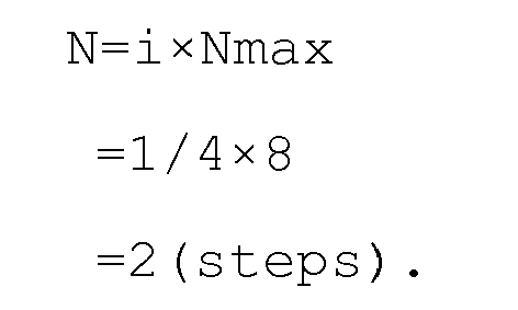
- At steps S215 and S216, the
MPU 20 performs same processes as the processes (steps S208 and S209) performed when the optimal driving step amount α is not stored. - At step S217, the
MPU 20 determines, in response to the determination that the N step movement is not set to α, whether or not the constant i is larger than 1. If the constant i is not larger than 1, theMPU 20 proceeds to step S218. If the constant i is larger than 1, theMPU 20 proceeds to step S220. - At step S218, the
MPU 20 sets the constant i to ix2 as follows in order to change the driving step amount N.
- Next, at step S219, the
MPU 20 calculates the driving step amount N again as follows, and then returns to step S211.
- At step S220, the
MPU 20 displays (informs) warning showing that it is impossible to perform the focus calibration. This is because the driving step amount N calculated with the constant i larger than 1 exceeds the maximum value Nmax, which makes it impossible to accurately perform the peak position detection. Thereafter, theMPU 20 ends the calibration mode. - When the focus calibration is at first performed by the processes at steps S208, S217 and S218, the
MPU 20 changes, with respect to Nmax, the driving step amount N first in steps of 1/4 step, next in steps of 1/2 step and finally in steps of one step. These step sizes are merely examples, so that other step sizes may be employed as long as capable of performing accurate peak position detection. - At step S221, the
MPU 20 that has detected the peak position sends, to thelens controller 23, an instruction to stop the drive of thefocus lens 3a. Thelens controller 23 stops the drive of thefocus lens 3a in response to this stop instruction. - Next, at step S222, the
MPU 20 ends the live-view display. Then, theMPU 20 closes ashutter 5 through ashutter driver 28, and rotates amain mirror 4 and asub mirror 7 to a down position through amotor driver 27. - Next, at step S223, the
MPU 20 performs focus detection by a phase difference detection method and calculates a phase difference in-focus position based on the focus detection result. - Next, at step S224, the
MPU 20 calculates a difference between the peak position (contrast in-focus position) obtained at step S213 and the phase difference in-focus position obtained at step S223. This difference is set to a CAL correction amount that is a correction amount for the phase difference in-focus position. - Thus, in this embodiment, the
MPU 20 outputs the instruction for theinterchangeable lens 3 to move thefocus lens 3a by the predetermined movement amount (driving step amount N) that is a target movement amount. In addition, theMPU 20 receives (acquires), from theinterchangeable lens 3, the information on the actual movement amount (pulse number N from the photo coupler 15) of thefocus lens 3a in response to the instruction. Then, theMPU 20 outputs again, to theinterchangeable lens 3, the instruction to move thefocus lens 3a with change of the predetermined movement amount when the actual movement amount does not coincide with the predetermined movement amount, that is, when the difference between the predetermined movement amount and the actual movement amount exceeds the predetermined value (or exceeds the predetermined range). Thus, theMPU 20 calculates the CAL correction amount by using the contrast in-focus position when the actual movement amount coincides with the predetermined movement amount, that is, when the difference between the predetermined movement amount and the actual movement amount is equal to or below the predetermined value (or within the predetermined range). - Next, at step S225, the
MPU 20 moves, through thelens controller 23, thefocus lens 3a to the infinitely far side by a third predetermined amount from the position where thefocus lens 3a has been stopped at step S221. At this step, thefocus lens 3a may be moved to the close side. - Next, at step S226, the
MPU 20 performs the focus detection by the phase difference detection method and calculates the phase difference in-focus position based on the focus detection result. - Then, at step S227, the
MPU 20 adds the CAL correction amount to the phase difference in-focus position calculated at step S226 to correct the phase difference in-focus position. Furthermore, theMPU 20 calculates a movement amount (lens in-focus driving amount) of thefocus lens 3a to the corrected phase difference in-focus position. Thereafter, theMPU 20 proceeds to step S228. - At step S228, the
MPU 20 sends information on the lens in-focus driving amount to thefocus controller 24 through thelens controller 23 to cause thefocus controller 24 to drive thefocus motor 13 by a rotation amount corresponding to the lens in-focus driving amount. Thereby, thefocus lens 3a is moved to the corrected phase difference in-focus position. - Next, at step S229, the
MPU 20 starts the live-view (LV) display on aliquid crystal display 12. - In addition, at step S230, the
MPU 20 determines whether or not a user having determined that the camera is focused on an object through the LV image displayed on theliquid crystal display 12 has performed an operation through amulti-control button 34 for selecting "OK". That is, theMPU 20 determines whether or not the user has decided to employ the CAL correction amount. At this step, the user can operate theelectronic dial 33 or themulti-control button 34 to enlarge part of the displayed LV image, which makes it easy for the user to strictly confirm whether or not an in-focus state is obtained. If "OK" is selected, theMPU 20 proceeds to step S231. If "OK" is not selected (that is, the user has operated themulti-control button 34 to select "NG"), theMPU 20 proceeds to step S234. - Although this embodiment displays the LV image on the
liquid crystal display 12 in order to cause the user to determine whether or not to employ the CAL correction amount, a test captured image data obtained by test image pickup may be displayed on theliquid crystal display 12 in order to cause the user to determine whether or not to employ the CAL correction amount. - At step S231, the
MPU 20 ends the live-view display. - Next, at step S232, the
MPU 20 stores the CAL correction amount calculated at step S224 in theEEPROM 22. - In addition, at step S233, the
MPU 20 stores the driving step amount N obtained when the peak position could be detected at step S213 as an optimal driving step amount α in theEEPROM 22. TheMPU 20 also stores, together with the optimal driving step amount α (in other words, in relation to the optimal driving step amount α), information on theinterchangeable lens 3 attached to thecamera body 1 including a type (model), a focal length, an F-number and an identification number thereof. Then, theMPU 20 ends the calibration mode. - On the other hand, at step S234, the
MPU 20 ends the Live-view display. - Next, at step S235, the
MPU 20 displays, on theliquid crystal monitor 12, that no correction of the phase difference in-focus position is made, that is, no focus calibration is performed, and then ends the calibration mode. - As described above, this embodiment can prevent the driving step amount of the
focus lens 3a in the peak position detection (contrast in-focus position detection) by the contrast detection method from exceeding the maximum value that enables accurate peak position detection. - Moreover, this embodiment can change, according to focus lens driving capability of the
interchangeable lens 3, the driving step amount of thefocus lens 3a to detect the contrast in-focus position that is used to calculate the CAL correction amount. Therefore, this embodiment can perform good calibration of the phase difference in-focus position (that is, good focus calibration), regardless of types, focus lens driving capability deterioration or the like of theinterchangeable lens 3 attached to thecamera body 1. - Moreover, this embodiment stores, when performing the focus calibration, the optimal driving step amount together with the information on the
interchangeable lens 3. Thus, this embodiment can use the stored optimal driving step amount when performing the focus calibration on the same interchangeable lens again. - In addition, this embodiment enables the user to decide whether or not to employ the calculated CAL correction amount.
- Although each of the above embodiments has described about the digital SLR camera as the image pickup apparatus and the interchangeable lens as the optical apparatus, the image pickup apparatus may be a digital still camera or a video camera other than the digital SLR camera, and the optical apparatus may be an optical apparatus whose image-pickup optical system is constituted optical elements other than lenses.
- While the present invention has been described with reference to exemplary embodiments, it is to be understood that the invention is not limited to the disclosed exemplary embodiments. The scope of the following claims is to be accorded the broadest interpretation so as to encompass all such modifications and equivalent structures and functions.
The image pickup apparatus electrically converts an object image to produce an image signal and includes a first detector (8, 20, 26) detecting a first in-focus position by a phase difference detection method, a second detector (21) detecting a second in-focus position by a contrast detection method using the image signal, and a corrector (20) correcting, based on a difference between the first and second in-focus positions, the first in-focus position for image pickup. A controller (20) instructs the optical apparatus to move the focus lens by a predetermined movement amount when the second in-focus position is detected, receives, from the optical apparatus, information on an actual movement amount of the focus lens in response to the instruction, and instructs again the optical apparatus to move the focus lens with change of the predetermined movement amount when a difference between the predetermined and actual movement amounts exceeds a predetermined value.
Claims (7)
- An image pickup apparatus (1) to which an optical apparatus (3) including an image-pickup optical system (3a, 3b, 17) is detachably attachable, the image pickup apparatus comprising:an image pickup device (6, 40, 41) configured to electrically convert an object image formed by the image-pickup optical system to produce an image pickup signal;a first detector (8, 20, 26) configured to detect a first in-focus position by a phase difference detection method;a second detector (21) configured to detect a second in-focus position by a contrast detection method using the image pickup signal;a corrector (20) configured to correct, based on a difference between the first and second in-focus positions, the first in-focus position for image pickup; anda controller (20) configured to be capable of communicating with the optical apparatus and configured to control drive of a focus lens (3a) included in the image-pickup optical system,characterized in that the controller is configured to output, to the optical apparatus, an instruction to move the focus lens by a predetermined movement amount when detection of the second in-focus position is made, and configured to receive, from the optical apparatus, information on an actual movement amount of the focus lens in response to the instruction, andwherein the controller is configured to output again, when a difference between the predetermined movement amount and the actual movement amount exceeds a predetermined value, to the optical apparatus, the instruction to move the focus lens with change of the predetermined movement amount.
- An image pickup apparatus (1) according to claim 1, wherein the corrector (20) is configured to correct the first in-focus position by using the second in-focus position detected by the contrast detection method when the difference between the predetermined movement amount and the actual movement amount is below the predetermined value.
- An image pickup apparatus (1) according to claim 1 or 2, wherein the controller (20) is configured to output again, when the difference between the predetermined movement amount and the actual movement amount exceeds the predetermined value, to the optical apparatus (3), the instruction to move the focus lens with increase of the predetermined movement amount.
- An image pickup apparatus (1) according to any one of claims 1 to 3, wherein the controller (20) is configured to output, when the difference between the predetermined movement amount changed to its upper limit and the actual movement amount exceeds the predetermined value, information showing that no correction of the first in-focus position is made.
- An image pickup apparatus (1) according to any one of claims 1 to 4, further comprising a selector (34) configured to enable a user to select whether or not to cause the corrector to correct the first in-focus position for the image pickup.
- An image pickup apparatus (1) according to any one of claims 1 to 5, further comprising a memory (22) configured to store the predetermined movement amount when the difference between that predetermined movement amount and the actual movement amount falls below the predetermined value.
- A control method of an image pickup apparatus (1) to which an optical apparatus (3) including an image-pickup optical system is detachably attachable and which includes an image pickup device (6, 40, 41) configured to electrically convert an object image formed by the image-pickup optical system (3a, 3b, 17) to produce an image pickup signal, the control method comprising the steps of:detecting a first in-focus position by a phase difference detection method;detecting a second in-focus position by a contrast detection method using the image pickup signal;correcting, based on a difference between the first and second in-focus positions, the first in-focus position for image pickup; andcontrolling drive of a focus lens included in the image-pickup optical system with communication with the optical apparatus,characterized in that the control method outputs, to the optical apparatus, an instruction to move the focus lens by a predetermined movement amount when detection of the second in-focus position is made, and receives, from the optical apparatus, information on an actual movement amount of the focus lens in response to the instruction, andthe control method outputs again, when a difference between the predetermined movement amount and the actual movement amount exceeds a predetermined value, to the optical apparatus, the instruction to move the focus lens with change of the predetermined movement amount.
Applications Claiming Priority (1)
| Application Number | Priority Date | Filing Date | Title |
|---|---|---|---|
| JP2011094620A JP5818494B2 (en) | 2011-04-21 | 2011-04-21 | Imaging apparatus and control method thereof |
Publications (2)
| Publication Number | Publication Date |
|---|---|
| EP2515525A2 true EP2515525A2 (en) | 2012-10-24 |
| EP2515525A3 EP2515525A3 (en) | 2013-05-22 |
Family
ID=46087444
Family Applications (1)
| Application Number | Title | Priority Date | Filing Date |
|---|---|---|---|
| EP12164899.2A Withdrawn EP2515525A3 (en) | 2011-04-21 | 2012-04-20 | Image pickup apparatus and control method thereof |
Country Status (4)
| Country | Link |
|---|---|
| US (1) | US20120268647A1 (en) |
| EP (1) | EP2515525A3 (en) |
| JP (1) | JP5818494B2 (en) |
| CN (1) | CN102761704A (en) |
Cited By (1)
| Publication number | Priority date | Publication date | Assignee | Title |
|---|---|---|---|---|
| WO2016144454A1 (en) * | 2015-03-10 | 2016-09-15 | Qualcomm Incorporated | Search range extension for depth assisted autofocus |
Families Citing this family (9)
| Publication number | Priority date | Publication date | Assignee | Title |
|---|---|---|---|---|
| JP2014178357A (en) * | 2013-03-13 | 2014-09-25 | Sony Corp | Digital microscope device, imaging method of the same and program |
| JP6287086B2 (en) * | 2013-11-11 | 2018-03-07 | 株式会社リコー | Imaging apparatus and image reading apparatus |
| JP6335482B2 (en) * | 2013-11-13 | 2018-05-30 | キヤノン株式会社 | Imaging apparatus, control method therefor, and program |
| FR3019556A1 (en) * | 2014-04-07 | 2015-10-09 | Advencis | INCUBATION AND DETECTION DEVICE |
| JP6296887B2 (en) * | 2014-05-07 | 2018-03-20 | キヤノン株式会社 | Focus adjustment apparatus and control method thereof |
| JP6500394B2 (en) * | 2014-11-12 | 2019-04-17 | リコーイメージング株式会社 | Imaging apparatus, imaging method and program |
| US12083045B2 (en) * | 2019-02-19 | 2024-09-10 | Alcon Inc. | Calibrating the position of the focal point of a laser beam |
| JP2020201378A (en) * | 2019-06-10 | 2020-12-17 | キヤノン株式会社 | Control device, imaging apparatus, control method, and program |
| CN113467033A (en) * | 2021-06-24 | 2021-10-01 | 南昌欧菲光电技术有限公司 | Camera module and lens positioning method thereof |
Citations (2)
| Publication number | Priority date | Publication date | Assignee | Title |
|---|---|---|---|---|
| JP2003295047A (en) | 2002-04-05 | 2003-10-15 | Canon Inc | Imaging device and imaging system |
| JP2009139728A (en) | 2007-12-07 | 2009-06-25 | Canon Inc | Control device |
Family Cites Families (12)
| Publication number | Priority date | Publication date | Assignee | Title |
|---|---|---|---|---|
| US5179407A (en) * | 1989-06-19 | 1993-01-12 | Nikon Corporation | Automatic focusing device |
| JP3557222B2 (en) * | 1992-04-28 | 2004-08-25 | オリンパス株式会社 | Automatic focusing device |
| JPH08154196A (en) * | 1994-11-25 | 1996-06-11 | Sanyo Electric Co Ltd | Automatic focusing video camera |
| JP2004237501A (en) * | 2003-02-04 | 2004-08-26 | Brother Ind Ltd | Carriage driving device and motor control method |
| JP4865275B2 (en) * | 2005-08-29 | 2012-02-01 | キヤノン株式会社 | Focus detection apparatus and imaging apparatus |
| JP4863370B2 (en) * | 2006-08-03 | 2012-01-25 | キヤノン株式会社 | Imaging device |
| JP2008275890A (en) * | 2007-04-27 | 2008-11-13 | Olympus Imaging Corp | Interchangeable lens digital camera |
| US8405759B2 (en) * | 2007-09-27 | 2013-03-26 | Olympus Imagining Corp. | Imaging device with contrast AF, and control method for imaging device with contrast AF |
| US8311407B2 (en) * | 2008-03-28 | 2012-11-13 | Panasonic Corporation | Camera system, camera body, and interchangeable lens |
| JP5480515B2 (en) * | 2008-03-28 | 2014-04-23 | パナソニック株式会社 | Camera system |
| JP5322783B2 (en) * | 2009-06-05 | 2013-10-23 | キヤノン株式会社 | IMAGING DEVICE AND CONTROL METHOD OF IMAGING DEVICE |
| JP5615017B2 (en) * | 2010-04-05 | 2014-10-29 | キヤノン株式会社 | Optical equipment |
-
2011
- 2011-04-21 JP JP2011094620A patent/JP5818494B2/en not_active Expired - Fee Related
-
2012
- 2012-04-16 US US13/447,964 patent/US20120268647A1/en not_active Abandoned
- 2012-04-20 EP EP12164899.2A patent/EP2515525A3/en not_active Withdrawn
- 2012-04-23 CN CN2012101210510A patent/CN102761704A/en active Pending
Patent Citations (2)
| Publication number | Priority date | Publication date | Assignee | Title |
|---|---|---|---|---|
| JP2003295047A (en) | 2002-04-05 | 2003-10-15 | Canon Inc | Imaging device and imaging system |
| JP2009139728A (en) | 2007-12-07 | 2009-06-25 | Canon Inc | Control device |
Cited By (2)
| Publication number | Priority date | Publication date | Assignee | Title |
|---|---|---|---|---|
| WO2016144454A1 (en) * | 2015-03-10 | 2016-09-15 | Qualcomm Incorporated | Search range extension for depth assisted autofocus |
| US9638984B2 (en) | 2015-03-10 | 2017-05-02 | Qualcomm Incorporated | Search range extension for depth assisted autofocus |
Also Published As
| Publication number | Publication date |
|---|---|
| JP2012226184A (en) | 2012-11-15 |
| US20120268647A1 (en) | 2012-10-25 |
| CN102761704A (en) | 2012-10-31 |
| JP5818494B2 (en) | 2015-11-18 |
| EP2515525A3 (en) | 2013-05-22 |
Similar Documents
| Publication | Publication Date | Title |
|---|---|---|
| EP2515525A2 (en) | Image pickup apparatus and control method thereof | |
| CN102547113B (en) | Image pickup device, control method thereof and program | |
| US7944499B2 (en) | Single lens reflex type electronic imaging apparatus | |
| US9497375B2 (en) | Image capturing apparatus, method of controlling the same, and storage medium | |
| US20090102960A1 (en) | Image pickup apparatus | |
| US7830422B2 (en) | Lens apparatus, image-pickup apparatus, and image-pickup system | |
| JP5932210B2 (en) | Imaging apparatus and focus adjustment method | |
| US20120249848A1 (en) | Image pickup apparatus, and control method and program thereof | |
| US7903154B2 (en) | Optical apparatus having control unit configured to reduce noise in captured image | |
| US20090092386A1 (en) | Image pickup apparatus | |
| JP2011090048A (en) | Automatic focus regulator for camera | |
| US7496290B2 (en) | Multipoint autofocus system and camera having multipoint autofocus system | |
| JP4804210B2 (en) | Imaging apparatus and control method thereof | |
| JP2009210872A (en) | Imaging device | |
| US7742694B2 (en) | Optical apparatus with aperture controller | |
| JP4847352B2 (en) | Imaging apparatus and control method thereof | |
| JP6544936B2 (en) | Control device of imaging device, imaging device and control method thereof | |
| JP5430314B2 (en) | Imaging apparatus and control method thereof | |
| JP4933035B2 (en) | IMAGING DEVICE AND IMAGING DEVICE CONTROL METHOD | |
| JP2009139728A (en) | Control device | |
| US20110091191A1 (en) | Imaging apparatus and focus control method for the imaging apparatus | |
| JP2013231883A (en) | Imaging device | |
| JP2007251656A (en) | Imaging apparatus, control method thereof, and program | |
| JP2017156371A (en) | Focus calibration system | |
| JP2020013050A (en) | Photographing parameter adjustment device, lens unit including the same, photographing parameter adjustment system, and photographing parameter adjustment method |
Legal Events
| Date | Code | Title | Description |
|---|---|---|---|
| PUAI | Public reference made under article 153(3) epc to a published international application that has entered the european phase |
Free format text: ORIGINAL CODE: 0009012 |
|
| AK | Designated contracting states |
Kind code of ref document: A2 Designated state(s): AL AT BE BG CH CY CZ DE DK EE ES FI FR GB GR HR HU IE IS IT LI LT LU LV MC MK MT NL NO PL PT RO RS SE SI SK SM TR |
|
| AX | Request for extension of the european patent |
Extension state: BA ME |
|
| PUAL | Search report despatched |
Free format text: ORIGINAL CODE: 0009013 |
|
| AK | Designated contracting states |
Kind code of ref document: A3 Designated state(s): AL AT BE BG CH CY CZ DE DK EE ES FI FR GB GR HR HU IE IS IT LI LT LU LV MC MK MT NL NO PL PT RO RS SE SI SK SM TR |
|
| AX | Request for extension of the european patent |
Extension state: BA ME |
|
| RIC1 | Information provided on ipc code assigned before grant |
Ipc: H04N 5/232 20060101AFI20130418BHEP |
|
| 17P | Request for examination filed |
Effective date: 20131122 |
|
| RBV | Designated contracting states (corrected) |
Designated state(s): AL AT BE BG CH CY CZ DE DK EE ES FI FR GB GR HR HU IE IS IT LI LT LU LV MC MK MT NL NO PL PT RO RS SE SI SK SM TR |
|
| GRAP | Despatch of communication of intention to grant a patent |
Free format text: ORIGINAL CODE: EPIDOSNIGR1 |
|
| RIN1 | Information on inventor provided before grant (corrected) |
Inventor name: NAKAGAWA, KAZUO |
|
| INTG | Intention to grant announced |
Effective date: 20150728 |
|
| RAP1 | Party data changed (applicant data changed or rights of an application transferred) |
Owner name: CANON KABUSHIKI KAISHA |
|
| STAA | Information on the status of an ep patent application or granted ep patent |
Free format text: STATUS: THE APPLICATION HAS BEEN WITHDRAWN |
|
| 18W | Application withdrawn |
Effective date: 20151118 |