EP2514970A1 - Transmission for wind power generation equipment, and wind power generation device - Google Patents
Transmission for wind power generation equipment, and wind power generation device Download PDFInfo
- Publication number
- EP2514970A1 EP2514970A1 EP10837362A EP10837362A EP2514970A1 EP 2514970 A1 EP2514970 A1 EP 2514970A1 EP 10837362 A EP10837362 A EP 10837362A EP 10837362 A EP10837362 A EP 10837362A EP 2514970 A1 EP2514970 A1 EP 2514970A1
- Authority
- EP
- European Patent Office
- Prior art keywords
- planetary
- carrier
- gear
- wind
- generator
- Prior art date
- Legal status (The legal status is an assumption and is not a legal conclusion. Google has not performed a legal analysis and makes no representation as to the accuracy of the status listed.)
- Withdrawn
Links
Images





Classifications
-
- F—MECHANICAL ENGINEERING; LIGHTING; HEATING; WEAPONS; BLASTING
- F03—MACHINES OR ENGINES FOR LIQUIDS; WIND, SPRING, OR WEIGHT MOTORS; PRODUCING MECHANICAL POWER OR A REACTIVE PROPULSIVE THRUST, NOT OTHERWISE PROVIDED FOR
- F03D—WIND MOTORS
- F03D1/00—Wind motors with rotation axis substantially parallel to the air flow entering the rotor
- F03D1/06—Rotors
-
- F—MECHANICAL ENGINEERING; LIGHTING; HEATING; WEAPONS; BLASTING
- F03—MACHINES OR ENGINES FOR LIQUIDS; WIND, SPRING, OR WEIGHT MOTORS; PRODUCING MECHANICAL POWER OR A REACTIVE PROPULSIVE THRUST, NOT OTHERWISE PROVIDED FOR
- F03D—WIND MOTORS
- F03D15/00—Transmission of mechanical power
-
- F—MECHANICAL ENGINEERING; LIGHTING; HEATING; WEAPONS; BLASTING
- F03—MACHINES OR ENGINES FOR LIQUIDS; WIND, SPRING, OR WEIGHT MOTORS; PRODUCING MECHANICAL POWER OR A REACTIVE PROPULSIVE THRUST, NOT OTHERWISE PROVIDED FOR
- F03D—WIND MOTORS
- F03D15/00—Transmission of mechanical power
- F03D15/10—Transmission of mechanical power using gearing not limited to rotary motion, e.g. with oscillating or reciprocating members
-
- F—MECHANICAL ENGINEERING; LIGHTING; HEATING; WEAPONS; BLASTING
- F03—MACHINES OR ENGINES FOR LIQUIDS; WIND, SPRING, OR WEIGHT MOTORS; PRODUCING MECHANICAL POWER OR A REACTIVE PROPULSIVE THRUST, NOT OTHERWISE PROVIDED FOR
- F03D—WIND MOTORS
- F03D80/00—Details, components or accessories not provided for in groups F03D1/00 - F03D17/00
- F03D80/70—Bearing or lubricating arrangements
-
- F—MECHANICAL ENGINEERING; LIGHTING; HEATING; WEAPONS; BLASTING
- F03—MACHINES OR ENGINES FOR LIQUIDS; WIND, SPRING, OR WEIGHT MOTORS; PRODUCING MECHANICAL POWER OR A REACTIVE PROPULSIVE THRUST, NOT OTHERWISE PROVIDED FOR
- F03D—WIND MOTORS
- F03D80/00—Details, components or accessories not provided for in groups F03D1/00 - F03D17/00
- F03D80/80—Arrangement of components within nacelles or towers
- F03D80/88—Arrangement of components within nacelles or towers of mechanical components
-
- F—MECHANICAL ENGINEERING; LIGHTING; HEATING; WEAPONS; BLASTING
- F16—ENGINEERING ELEMENTS AND UNITS; GENERAL MEASURES FOR PRODUCING AND MAINTAINING EFFECTIVE FUNCTIONING OF MACHINES OR INSTALLATIONS; THERMAL INSULATION IN GENERAL
- F16C—SHAFTS; FLEXIBLE SHAFTS; ELEMENTS OR CRANKSHAFT MECHANISMS; ROTARY BODIES OTHER THAN GEARING ELEMENTS; BEARINGS
- F16C17/00—Sliding-contact bearings for exclusively rotary movement
- F16C17/02—Sliding-contact bearings for exclusively rotary movement for radial load only
-
- F—MECHANICAL ENGINEERING; LIGHTING; HEATING; WEAPONS; BLASTING
- F16—ENGINEERING ELEMENTS AND UNITS; GENERAL MEASURES FOR PRODUCING AND MAINTAINING EFFECTIVE FUNCTIONING OF MACHINES OR INSTALLATIONS; THERMAL INSULATION IN GENERAL
- F16C—SHAFTS; FLEXIBLE SHAFTS; ELEMENTS OR CRANKSHAFT MECHANISMS; ROTARY BODIES OTHER THAN GEARING ELEMENTS; BEARINGS
- F16C17/00—Sliding-contact bearings for exclusively rotary movement
- F16C17/04—Sliding-contact bearings for exclusively rotary movement for axial load only
-
- F—MECHANICAL ENGINEERING; LIGHTING; HEATING; WEAPONS; BLASTING
- F16—ENGINEERING ELEMENTS AND UNITS; GENERAL MEASURES FOR PRODUCING AND MAINTAINING EFFECTIVE FUNCTIONING OF MACHINES OR INSTALLATIONS; THERMAL INSULATION IN GENERAL
- F16C—SHAFTS; FLEXIBLE SHAFTS; ELEMENTS OR CRANKSHAFT MECHANISMS; ROTARY BODIES OTHER THAN GEARING ELEMENTS; BEARINGS
- F16C33/00—Parts of bearings; Special methods for making bearings or parts thereof
- F16C33/02—Parts of sliding-contact bearings
- F16C33/04—Brasses; Bushes; Linings
- F16C33/06—Sliding surface mainly made of metal
- F16C33/10—Construction relative to lubrication
- F16C33/1025—Construction relative to lubrication with liquid, e.g. oil, as lubricant
- F16C33/1045—Details of supply of the liquid to the bearing
- F16C33/1055—Details of supply of the liquid to the bearing from radial inside, e.g. via a passage through the shaft and/or inner sleeve
-
- F—MECHANICAL ENGINEERING; LIGHTING; HEATING; WEAPONS; BLASTING
- F16—ENGINEERING ELEMENTS AND UNITS; GENERAL MEASURES FOR PRODUCING AND MAINTAINING EFFECTIVE FUNCTIONING OF MACHINES OR INSTALLATIONS; THERMAL INSULATION IN GENERAL
- F16H—GEARING
- F16H3/00—Toothed gearings for conveying rotary motion with variable gear ratio or for reversing rotary motion
- F16H3/44—Toothed gearings for conveying rotary motion with variable gear ratio or for reversing rotary motion using gears having orbital motion
- F16H3/46—Gearings having only two central gears, connected by orbital gears
- F16H3/48—Gearings having only two central gears, connected by orbital gears with single orbital gears or pairs of rigidly-connected orbital gears
- F16H3/52—Gearings having only two central gears, connected by orbital gears with single orbital gears or pairs of rigidly-connected orbital gears comprising orbital spur gears
- F16H3/54—Gearings having only two central gears, connected by orbital gears with single orbital gears or pairs of rigidly-connected orbital gears comprising orbital spur gears one of the central gears being internally toothed and the other externally toothed
-
- F—MECHANICAL ENGINEERING; LIGHTING; HEATING; WEAPONS; BLASTING
- F16—ENGINEERING ELEMENTS AND UNITS; GENERAL MEASURES FOR PRODUCING AND MAINTAINING EFFECTIVE FUNCTIONING OF MACHINES OR INSTALLATIONS; THERMAL INSULATION IN GENERAL
- F16H—GEARING
- F16H37/00—Combinations of mechanical gearings, not provided for in groups F16H1/00 - F16H35/00
- F16H37/02—Combinations of mechanical gearings, not provided for in groups F16H1/00 - F16H35/00 comprising essentially only toothed or friction gearings
- F16H37/04—Combinations of toothed gearings only
- F16H37/041—Combinations of toothed gearings only for conveying rotary motion with constant gear ratio
-
- F—MECHANICAL ENGINEERING; LIGHTING; HEATING; WEAPONS; BLASTING
- F16—ENGINEERING ELEMENTS AND UNITS; GENERAL MEASURES FOR PRODUCING AND MAINTAINING EFFECTIVE FUNCTIONING OF MACHINES OR INSTALLATIONS; THERMAL INSULATION IN GENERAL
- F16H—GEARING
- F16H57/00—General details of gearing
- F16H57/04—Features relating to lubrication or cooling or heating
- F16H57/0467—Elements of gearings to be lubricated, cooled or heated
- F16H57/0479—Gears or bearings on planet carriers
-
- F—MECHANICAL ENGINEERING; LIGHTING; HEATING; WEAPONS; BLASTING
- F16—ENGINEERING ELEMENTS AND UNITS; GENERAL MEASURES FOR PRODUCING AND MAINTAINING EFFECTIVE FUNCTIONING OF MACHINES OR INSTALLATIONS; THERMAL INSULATION IN GENERAL
- F16H—GEARING
- F16H57/00—General details of gearing
- F16H57/08—General details of gearing of gearings with members having orbital motion
- F16H57/082—Planet carriers
-
- F—MECHANICAL ENGINEERING; LIGHTING; HEATING; WEAPONS; BLASTING
- F05—INDEXING SCHEMES RELATING TO ENGINES OR PUMPS IN VARIOUS SUBCLASSES OF CLASSES F01-F04
- F05B—INDEXING SCHEME RELATING TO WIND, SPRING, WEIGHT, INERTIA OR LIKE MOTORS, TO MACHINES OR ENGINES FOR LIQUIDS COVERED BY SUBCLASSES F03B, F03D AND F03G
- F05B2260/00—Function
- F05B2260/40—Transmission of power
- F05B2260/403—Transmission of power through the shape of the drive components
- F05B2260/4031—Transmission of power through the shape of the drive components as in toothed gearing
- F05B2260/40311—Transmission of power through the shape of the drive components as in toothed gearing of the epicyclic, planetary or differential type
-
- F—MECHANICAL ENGINEERING; LIGHTING; HEATING; WEAPONS; BLASTING
- F16—ENGINEERING ELEMENTS AND UNITS; GENERAL MEASURES FOR PRODUCING AND MAINTAINING EFFECTIVE FUNCTIONING OF MACHINES OR INSTALLATIONS; THERMAL INSULATION IN GENERAL
- F16C—SHAFTS; FLEXIBLE SHAFTS; ELEMENTS OR CRANKSHAFT MECHANISMS; ROTARY BODIES OTHER THAN GEARING ELEMENTS; BEARINGS
- F16C2360/00—Engines or pumps
- F16C2360/31—Wind motors
-
- F—MECHANICAL ENGINEERING; LIGHTING; HEATING; WEAPONS; BLASTING
- F16—ENGINEERING ELEMENTS AND UNITS; GENERAL MEASURES FOR PRODUCING AND MAINTAINING EFFECTIVE FUNCTIONING OF MACHINES OR INSTALLATIONS; THERMAL INSULATION IN GENERAL
- F16C—SHAFTS; FLEXIBLE SHAFTS; ELEMENTS OR CRANKSHAFT MECHANISMS; ROTARY BODIES OTHER THAN GEARING ELEMENTS; BEARINGS
- F16C2361/00—Apparatus or articles in engineering in general
- F16C2361/61—Toothed gear systems, e.g. support of pinion shafts
-
- F—MECHANICAL ENGINEERING; LIGHTING; HEATING; WEAPONS; BLASTING
- F16—ENGINEERING ELEMENTS AND UNITS; GENERAL MEASURES FOR PRODUCING AND MAINTAINING EFFECTIVE FUNCTIONING OF MACHINES OR INSTALLATIONS; THERMAL INSULATION IN GENERAL
- F16H—GEARING
- F16H57/00—General details of gearing
- F16H57/08—General details of gearing of gearings with members having orbital motion
- F16H2057/085—Bearings for orbital gears
-
- F—MECHANICAL ENGINEERING; LIGHTING; HEATING; WEAPONS; BLASTING
- F16—ENGINEERING ELEMENTS AND UNITS; GENERAL MEASURES FOR PRODUCING AND MAINTAINING EFFECTIVE FUNCTIONING OF MACHINES OR INSTALLATIONS; THERMAL INSULATION IN GENERAL
- F16H—GEARING
- F16H57/00—General details of gearing
- F16H57/04—Features relating to lubrication or cooling or heating
- F16H57/048—Type of gearings to be lubricated, cooled or heated
- F16H57/0482—Gearings with gears having orbital motion
- F16H57/0486—Gearings with gears having orbital motion with fixed gear ratio
-
- Y—GENERAL TAGGING OF NEW TECHNOLOGICAL DEVELOPMENTS; GENERAL TAGGING OF CROSS-SECTIONAL TECHNOLOGIES SPANNING OVER SEVERAL SECTIONS OF THE IPC; TECHNICAL SUBJECTS COVERED BY FORMER USPC CROSS-REFERENCE ART COLLECTIONS [XRACs] AND DIGESTS
- Y02—TECHNOLOGIES OR APPLICATIONS FOR MITIGATION OR ADAPTATION AGAINST CLIMATE CHANGE
- Y02E—REDUCTION OF GREENHOUSE GAS [GHG] EMISSIONS, RELATED TO ENERGY GENERATION, TRANSMISSION OR DISTRIBUTION
- Y02E10/00—Energy generation through renewable energy sources
- Y02E10/70—Wind energy
- Y02E10/72—Wind turbines with rotation axis in wind direction
Definitions
- the present invention relates to wind-turbine-generator-system transmissions and wind turbine generators.
- a transmission such as a transmission that uses a planetary gear, provided therein converts the rotational force to a rotational speed appropriate for generating power.
- Transmissions that use planetary gears are known to have high output conversion efficiency as compared with transmissions of other types (for example, see Patent Literature 1).
- a planetary gear is mainly provided with a sun gear, a planetary gear, inner teeth, and the like, and the planetary gear is supported in a resolvable and rotatable manner around the sun gear by a carrier and a planetary pin connected to a main shaft that receives the rotational force from the blades.
- a bearing structure such as a roller bearing or a slide bearing, is provided between the planetary gear and the planetary pin.
- a slide bearing is advantageous in that it has a longer life span than a roller bearing and can allow for noise reduction and lower manufacturing costs.
- a slide bearing there is a problem in that it is difficult to both minimize seizing and abrasion of the slide bearing and ensure the strength of the carrier and the planetary pin at the same time.
- the present invention has been made to solve the aforementioned problems, and an object thereof is to provide a wind-turbine-generator-system transmission and a wind turbine generator that can ensure the strength of a bearing and can also minimize seizing and abrasion.
- a wind-turbine-generator-system transmission having a sun gear, a planetary gear that meshes with the sun gear and rotates around the sun gear, and an inner tooth that meshes with the planetary gear
- the transmission includes a carrier that rotates the planetary gear around the sun gear; a planetary pin that is disposed in the carrier and transmits rotation of the carrier to the planetary gear; a cylindrical sleeve disposed around a periphery of the planetary pin; and a slide bearing that is disposed between the sleeve and the planetary gear and supports the planetary gear in a rotatable manner about the planetary pin.
- the planetary gear is rotatably supported between the sleeve and the slide bearing in a state where the planetary pin is disposed in the carrier and the cylindrical sleeve is disposed around the periphery of the planetary pin, the strength of the bearing in the wind-turbine-generator-system transmission can be ensured, and seizing and abrasion can be minimized.
- the contact area related to the slide bearing i.e., the contact area between the sleeve and the slide bearing
- the contact pressure is reduced.
- seizing and abrasion of the slide bearing can be minimized.
- the diameter of the planetary pin itself disposed in the carrier is not increased, an increase in stress on the mating surface or the like between the planetary pin and the carrier is minimized. Therefore, reduction of strength in the planetary pin and the carrier can be minimized.
- the carrier be formed of two plate members that face each other, the planetary pin be disposed so as to extend through the plate members, and the planetary gear and the sleeve be disposed between the two plate members.
- the diameter of parts of the planetary pin and the sleeve that are in contact with the slide bearing can be increased so that the contact pressure on the slide bearing can be reduced.
- the diameter of the part of the planetary pin that is fitted in the carrier remains small so that an increase in stress on the mating surface or the like between the planetary pin and the carrier can be minimized.
- a flow channel that supplies a lubricant between the slide bearing and the sleeve be formed in the planetary pin and the sleeve.
- a lubrication layer made of the lubricant, such as lubricating oil, is formed between the slide bearing and the sleeve. Therefore, seizing and abrasion between the slide bearing and the sleeve can be minimized.
- the lubricant stored in the reservoir is supplied between the sleeve and the slide bearing. Therefore, a lubrication layer can be readily formed between the sleeve and the slide bearing, as compared with when the lubricant is simply supplied from the flow channel, whereby seizing and abrasion between the slide bearing and the sleeve can be more reliably minimized.
- the planetary pin be provided with a hole that extends from an end surface of the planetary pin toward an interior of the planetary pin.
- the hole to adjust the temperature of the planetary pin
- temperature adjustment can be readily performed, as compared with when not using the hole.
- the hole provided in the planetary pin the planetary pin can be readily secured and disposed in the carrier.
- the planetary pin alone can be cooled, the planetary pin can be readily removed from the carrier.
- a thrust-receiving section be provided between the carrier and at least one of the slide bearing and the planetary gear.
- a wind turbine generator includes a rotor blade that rotates around a main shaft by receiving wind; the wind-turbine-generator-system transmission according to the first aspect that increases or decreases the rotation speed of the main shaft; and a generator unit that generates power by being rotationally driven by the wind-turbine-generator-system transmission.
- the strength of the bearing in the wind turbine generator can be ensured, as well as minimizing seizing and abrasion.
- the wind-turbine-generator-system transmission and the wind turbine generator according to the present invention are advantageous in that, since the planetary gear is rotatably supported between the sleeve and the slide bearing in a state where the planetary pin is disposed in the carrier and the cylindrical sleeve is disposed around the periphery of the planetary pin, the strength of the bearing in the wind-turbine-generator-system transmission and in the wind turbine generator can be ensured, and seizing and abrasion can be minimized.
- FIG. 1 is a schematic diagram explaining the overall configuration of the wind turbine generator according to this embodiment.
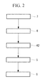
- Fig. 2 is a block diagram explaining a transmission path of a rotational driving force in the wind turbine generator in Fig. 1 .
- a wind turbine generator system (wind turbine generator) 1 is a so-called upwind-type wind turbine generator system and is configured to perform wind power generation by receiving wind.
- the wind turbine generator system 1 is provided with a tower 2, a nacelle 3, a hub 4, a plurality of rotor blades 7, a gear box (wind-turbine-generator-system transmission) 5, and a generator (generator unit) 6.
- the tower 2 has a columnar structure extending upward (upward in Fig. 1 ) from a foundation and is constituted of a plurality of units that are connected in the vertical direction.
- the nacelle 3 is provided at the uppermost part of the tower 2. When the tower 2 is constituted of the plurality of units, the nacelle 3 is set on top of the uppermost unit.
- the nacelle 3 rotatably supports the hub 4 and accommodates therein the generator 6 that performs power generation in accordance with the rotation of the hub 4.
- the nacelle 3 is provided with, for example, an opening through which a main shaft 42 that transmits a rotational driving force of the hub 4 extends, as well as an entrance door used for maintenance.
- the multiple rotor blades 7 extending radially about a rotation axis L of the hub 4 are attached thereto at equal intervals in the circumferential direction.
- the hub 4 is provided in a rotatable manner around the rotation axis L relative to the nacelle 3, and the periphery thereof is covered by a head capsule 41.
- the rotor blades 7 are attached in a radiating pattern around the rotation axis L of the hub 4. Although this embodiment is described as being applied to an example provided with three rotor blades 7, the number of rotor blades 7 is not limited to three and may alternatively be two or more than three; it is not particularly limited.
- Fig. 3 is a schematic diagram explaining the configuration of the gear box in Fig. 1 .
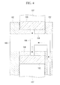
- Fig. 4 is a partially enlarged diagram explaining the configuration of a planetary gear and its surrounding area in the gear box in Fig. 3 .
- Fig. 5 is a schematic diagram explaining the configuration of a planetary pin and a sleeve in Fig. 4 .
- the gear box 5 is configured to increase the speed of the rotational driving force transmitted by the main shaft 42 to a rotation speed appropriate for driving the generator 6.
- the gear box 5 is mainly provided with a planetary gear unit 51, a low-speed gear unit 52, a mid-speed gear unit 53, and a high-speed gear unit 54.
- the planetary gear unit 51 is configured to initially increase the speed of the rotational driving force transmitted by the main shaft 42 and input the rotational driving force to the low-speed gear unit 52.
- the planetary gear unit 51 is mainly provided with an input shaft 101, a carrier 102, a planetary pin 103, a sleeve 104, a slide bearing 105, a lubricating-oil supply channel (flow channel) 106, a planetary gear 107, inner teeth 108, a sun gear 109, and an output shaft 110.
- the input shaft 101 is a part that receives the rotational driving force from the main shaft 42 and is configured to transmit the rotational driving force to the carrier 102.
- the input shaft 101 is a columnar or cylindrical member and is rotatably supported around a central axis.
- the carrier 102 is provided at an end of the input shaft 101 adjacent to the sun gear 109 (i.e., the right end thereof in Fig. 3 ).
- the carrier 102 is a part that receives the rotational driving force from the input shaft 101 and is configured to rotate (revolve) the planetary gear 107 around the sun gear 109.
- the carrier 102 is constituted of a plate member extending radially outward in the form of a flange from the end of the input shaft 101, a ring-shaped plate member disposed facing the aforementioned plate member, and a pillar member connecting the two plate members.
- the planetary gear 107 is disposed between the two plate members of the carrier 102.
- the planetary pin 103 is configured to attach the sleeve 104, the slide bearing 105, and the planetary gear 107 to the carrier 102 and support the planetary gear 107 in a rotatable manner about the planetary pin 103.
- the planetary pin 103 is a columnar member and is fitted in a through-hole formed in the two plate members of the carrier 102.
- the sleeve 104 is configured to attach the planetary pin 103, the slide bearing 105, and the planetary gear 107 to the carrier 102 and support the planetary gear 107 in a rotatable manner about the planetary pin 103.
- the sleeve 104 is a cylindrical member and is disposed between the two plate members of the carrier 102. Furthermore, the sleeve 104 has the planetary pin fitted therein and is composed of a material having the same coefficient of linear expansion as that of the planetary pin 103, for example, the same material as that used for the planetary pin 103. Accordingly, even when the temperature of the planetary pin 103 and the sleeve 104 changes, overstress and gap formation between the planetary pin 103 and the sleeve 104 can be prevented.
- the slide bearing 105 is configured to attach the planetary pin 103, the sleeve 104, and the planetary gear 107 to the carrier 102 and support the planetary gear 107 in a rotatable manner about the planetary pin 103.
- the slide bearing 105 is a cylindrical member and is attached to the planetary gear 107. Therefore, a contact surface between the sleeve 104 and the slide bearing 105 acts as a sliding surface.
- the lubricating-oil supply channel 106 is a flow channel for supplying lubricating oil to the contact surface between the sleeve 104 and the slide bearing 105.
- the lubricating-oil supply channel 106 extends from the carrier 102 to the interior of the planetary pin 103 and diverges into two flow channels inside the planetary pin 103 before the two flow channels open to the outer periphery of the sleeve 104.
- One of the two openings of the lubricating-oil supply channel 106 is provided in a load surface on the outer periphery of the sleeve 104, whereas the other opening is provided in a counter load surface thereof.
- the term "load surface” is a surface that receives load when the rotational driving force is transmitted, and is the lower surface in Figs. 3 and 4 .
- the term "counter load surface” is a surface opposite the load surface and is the upper surface.
- the lubricating oil can be supplied to a part where the contact pressure becomes high on the outer periphery of the sleeve 104 when the wind turbine generator system 1 performs power generation, that is, when the rotational driving force is transmitted to the generator 6.
- the lubricating oil can be supplied to a part where the contact pressure becomes high, that is, the counter load surface, when, for example, a braking force is applied for reducing the rotation speed of the wind turbine due to an increasing wind speed.
- the planetary gear 107 meshes with the sun gear 109 and the inner teeth 108 so as to constitute a planetary speed-reducing mechanism.
- the planetary gear 107 is rotatably supported by the carrier 102 via the planetary pin 103, the sleeve 104, and the slide bearing 105, and is made by forming teeth around the outer periphery of a cylinder supported in a revolvable manner relative to the sun gear 109.
- this embodiment is described as being applied to an example in which three planetary gears 107 are arranged at equal intervals in the circumferential direction, the number of planetary gears 107 is not particularly limited.
- the inner teeth 108 mesh with the planetary gear 107 so as to constitute the planetary speed-reducing mechanism.
- the inner teeth 108 are formed at a position facing the planetary gear 107 within the inner surface of a casing 108A that covers the carrier 102, the planetary gear 107, the sun gear 109, and the like.
- the inner teeth 108 are configured to mesh with the planetary gear 107 at an outer side thereof in the radial direction about the input shaft 101.
- the sun gear 109 meshes with the planetary gear 107 so as to constitute the planetary speed-reducing mechanism.
- the sun gear 109 is formed of a column or a cylinder having teeth formed on the outer periphery thereof, and is formed coaxially with the output shaft 110.
- the sun gear 109 and the output shaft 110 are disposed substantially coaxially with the input shaft 101 and are configured to mesh with the planetary gear 107 at an inner side thereof in the radial direction around the input shaft 101.
- the output shaft 110 is configured to transmit the rotational driving force, whose rotation speed has been increased by the planetary gear unit 51, to the low-speed gear unit 52.
- the output shaft 110 is disposed coaxially with the sun gear 109 and is also disposed substantially coaxially with the input shaft 101.
- the low-speed gear unit 52 is configured to further increase the speed of the rotational driving force, whose rotation speed has been increased by the planetary gear unit 51, and input the rotational driving force to the mid-speed gear unit 53.
- the low-speed gear unit 52 is mainly provided with a low-speed clear 111.
- the low-speed gear 111 meshes with a small mid-speed gear 112 and has a diameter larger than that of the small mid-speed gear 112.
- the low-speed gear 111 is provided coaxially with the output shaft 110 of the planetary gear unit 51.
- the mid-speed gear unit 53 is configured to further increase the speed of the rotational driving force, whose rotation speed has been increased by the low-speed gear unit 52, and input the rotational driving force to the high-speed gear unit 54.
- the mid-speed gear unit 53 is mainly provided with the small mid-speed gear 112 and a large mid-speed gear 113.
- the small mid-speed gear 112 meshes with the low-speed gear 111 and has a diameter smaller than that of the low-speed gear 111.
- the large mid-speed gear 113 meshes with a high-speed gear 115 and has a diameter larger than that of the high-speed gear 115.
- the small mid-speed gear 112 and the large mid-speed gear 113 are provided coaxially with a mid-speed shaft 114.
- the high-speed gear unit 54 is configured to further increase the speed of the rotational driving force, whose rotation speed has been increased by the mid-speed gear unit 53, and input the rotational driving force to the generator 6.
- the high-speed gear unit 54 is mainly provided with the high-speed gear 115.
- the high-speed gear 115 meshes with the large mid-speed gear 113 and has a diameter smaller than that of the large mid-speed gear.
- the high-speed gear 115 is provided coaxially with a high-speed shaft 116 that transmits the rotational driving force to the generator 6.
- the generator 6 is configured to generate power by being rotationally driven by the rotation of the hub 4 transmitted via the main shaft 42 and the gear box 5.
- the rotor blades 7 of the wind turbine generator system 1 rotate around the hub 4 by receiving wind so as to generate a rotational driving force, and rotationally driven the hub 4 and the main shaft 42 connected to the hub 4.
- the rotational driving force is input to the input shaft 101 of the gear box 5 from the main shaft 42, and the input shaft 101 and the carrier 102 are rotated around the central axis by the rotational driving force.
- the carrier 102 rotates, the planetary gear 107 is rotationally driven around the sun gear 109 via the planetary pin 103, the sleeve 104, and the slide bearing 105.
- the planetary gear 107 is meshed with the inner teeth 108 and the sun gear 109, the planetary gear 107 is also rotationally driven about the planetary pin 103. Consequently, the rotation of the input shaft 101 is increased in speed and is transmitted to the sun gear 109 and the output shaft 110.
- the rotation of the output shaft 110 is transmitted to the small mid-speed gear 112 of the mid-speed gear unit 53 from the low-speed gear 111 of the low-speed gear unit 52 and is further increased in speed.
- the rotation of the small mid-speed gear 112 is transmitted to the high-speed gear 115 of the high-speed gear unit 54 from the large mid-speed gear 113 via the mid-speed shaft 114, and is increased in speed to a speed appropriate for rotationally driving the generator 6.
- the rotation of the high-speed gear 115 is transmitted to the generator 6 via the high-speed shaft 116 so as to rotationally derive the generator 6, whereby power is generated.
- the lubricating oil related to the rotation of the planetary gear 107 is supplied between the sleeve 104 and the slide bearing 105 via the lubricating-oil supply channel 106.
- the lubricating oil supplied to the lubricating-oil supply channel 106 through an opening provided in the carrier 102 flows inside the carrier 102 and the planetary pin 103 and subsequently diverges in two directions before flowing outward through the openings provided in the load surface and the counter load surface on the outer periphery of the sleeve 104.
- a lubrication layer made of the lubricating oil is formed between the sleeve 104 secured to the carrier 102 via the planetary pin 103 and the slide bearing 105 secured to the planetary gear 107, whereby the planetary gear 107 is supported in a rotatable manner about the planetary pin 103.
- the planetary gear 107 is rotatably supported between the sleeve 104 and the slide bearing 105 in a state where the planetary pin 103 is disposed in the carrier 102 and the cylindrical sleeve 104 is disposed around the periphery of the planetary pin 103, the strength of the bearing in the gear box 5 of the wind turbine generator system 1 can be ensured, and seizing and abrasion can be minimized.
- the contact area related to the slide bearing 105 i.e., the contact area between the sleeve 104 and the slide bearing 105
- contact pressure is reduced.
- seizing and abrasion of the slide bearing 105 can be minimized.
- the diameter of the planetary pin 103 itself disposed in the carrier 102 is not increased, an increase in stress on the mating surface or the like between the planetary pin 103 and the carrier 102 is minimized. Therefore, reduction of strength in the planetary pin 103 and the carrier 102 can be minimized.
- the diameter of parts of the planetary pin 103 and the sleeve 104 that are in contact with the slide bearing 105 can be increased so that the contact pressure on the slide bearing 105 can be reduced.
- the diameter of the part of the planetary pin 103 that is fitted in the carrier 102 remains small so that an increase in stress on the mating surface or the like between the planetary pin 103 and the carrier 102 can be minimized.
- the lubrication layer made of the lubricating oil is formed between the slide bearing 105 and the sleeve 104. Therefore, seizing and abrasion between the slide bearing 105 and the sleeve 104 can be minimized.
- Figs. 6 and 7 are partially enlarged diagram explaining the configuration of the planetary gear unit in the wind turbine generator system according to this embodiment.
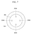
- Fig. 7 is a schematic diagram explaining the configuration of a planetary pin in Fig. 6 . Components that are the same as those in the first embodiment are given the same reference numerals, and descriptions thereof will be omitted.
- a gear box (wind-turbine-generator-system transmission) 205 in a wind turbine generator system (wind turbine generator) 201 in this embodiment is mainly provided with a carrier 102, a planetary pin 203, a sleeve 104, a slide bearing 105, a lubricating-oil supply channel 106, a planetary gear 107, and the like.
- the planetary pin 203 is provided with cooling sections (holes) 203A used for cooling the planetary pin 203.
- the cooling sections 203A are holes that extend longitudinally (i.e., in the left-right direction in Fig. 6 ) from end surfaces of the planetary pin 203 and are provided at equal intervals in the circumferential direction.
- the cooling sections 203A are described as being non-through-holes in this embodiment, the cooling sections 203A are not particularly limited thereto and may alternatively be through-holes so long as they are not in communication with the lubricating-oil supply channel 106.
- this embodiment is described as being applied to an example in which four cooling sections 203A are arranged at equal intervals in the circumferential direction, the number of cooling sections 203A is not particularly limited.
- the planetary pin 203 is secured in place by being fitted into a through-hole formed in the carrier 102.
- the planetary pin 203 is cooled so as to reduce the diameter thereof, and is inserted in this state into the aforementioned through-hole.
- cooling members are inserted into the cooling sections 203A so that the temperature of the entire planetary pin 203 is lowered.
- the planetary pin 203 expands in accordance with the coefficient of linear expansion of the material thereof, whereby the fitting process between the planetary pin 203 and the carrier 102 is completed.
- the planetary pin 203 is removed from the carrier 102.
- the cooling members are inserted into the cooling sections 203A so that the temperature of the entire planetary pin 203 alone is lowered. This causes the diameter of the planetary pin 203 to become smaller with decreasing temperature, whereas the diameter of the through-hole of the carrier 102 does not change. Consequently, the planetary pin 203 can be removed from the carrier 102.
- the cooling process can be performed readily, as compared with when the cooling sections 203A are not used.
- the cooling sections 203A provided in the planetary pin 203 are used so that the planetary pin 203 can be readily secured and disposed in the carrier 102.
- the planetary pin 203 alone can be cooled, the planetary pin 203 can be readily removed from the carrier 102.
- a third embodiment of the present invention will be described with reference to Fig. 8 .
- the basic configuration of a wind turbine generator system in this embodiment is similar to that in the first embodiment, the configuration of a planetary gear unit differs from that in the first embodiment. Therefore, in this embodiment, only the configuration of the planetary gear unit will be described using Fig. 8 , and descriptions of other components will be omitted.
- Fig. 8 is a partially enlarged diagram explaining the configuration of the planetary gear unit in the wind turbine generator system according to this embodiment. Components that are the same as those in the first embodiment are given the same reference numerals, and descriptions thereof will be omitted.
- a gear box (wind-turbine-generator-system transmission) 305 in a wind turbine generator system (wind turbine generator) 301 in this embodiment is mainly provided with a carrier 102, a planetary pin 103, a sleeve 104, a slide bearing 105, a lubricating-oil supply channel 106, a planetary gear 107, thrust-receiving sections 309, and the like.
- the thrust-receiving sections 309 are ring-plate-like members disposed between the carrier 102, the sleeve 104, the slide bearing 105, and the planetary gear 107, and are in contact with end surfaces of the planetary gear 107 and the slide bearing 105 that rotate relative to the carrier 102. Moreover, the thrust-receiving sections 309 are composed of a material having lubricity, such as plastic or copper alloy.
- a force in the longitudinal direction of the planetary pin 103 does not act on the slide bearing 105 and the planetary gear 107 even when a rotational driving force is transmitted in the gear box 305, and the slide bearing 105 and the planetary gear 107 do not come into contact with the carrier 102.
- the force in the longitudinal direction of the planetary pin 103 is applied to the slide bearing 105 and the planetary gear 107, causing the slide bearing 105 and the planetary gear 107 to move in the same direction. Then, the slide bearing 105 and the planetary gear 107 come into contact with the thrust-receiving sections 309 and slide between the thrust-receiving sections 309.
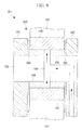
- Figs. 9 and 10 are partially enlarged diagram explaining the configuration of a planetary gear unit in the wind turbine generator system according to this embodiment.
- Fig. 10 is a schematic diagram explaining the configuration of a planetary pin in Fig. 9 . Components that are the same as those in the first embodiment are given the same reference numerals, and descriptions thereof will be omitted.
- a gear box (wind-turbine-generator-system transmission) 405 in a wind turbine generator system (wind turbine generator) 401 in this embodiment is mainly provided with a carrier 102, a planetary pin 103, a sleeve 404, a slide bearing 105, a lubricating-oil supply channel 106, a planetary gear 107, and the like.
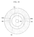
- cutout sections 404A that form reservoirs 406 for storing lubricating oil between the cutout sections 404A and the slide bearing 105 are formed in the sleeve 404.
- Each cutout section 404A is made of a flat surface formed on the outer periphery of the sleeve 404 and is formed at a position distant from each opening of the lubricating-oil supply channel 106 formed in the outer periphery of the sleeve 404 by a phase of about 90°.
- the reservoirs 406 can be formed without having to reduce the area of a load surface and a counter load surface in the sleeve 404.
- the reservoirs 406 store a portion of the lubricating oil supplied from the lubricating-oil supply channel 106, and the lubricating oil stored in the reservoirs 406 is supplied between the sleeve 404 and the slide bearing 105. Therefore, a lubrication layer can be readily formed between the sleeve 404 and the slide bearing 105, as compared with when the lubricating oil is simply supplied from the lubricating-oil supply channel 106, whereby seizing and abrasion between the slide bearing 105 and the sleeve 404 can be more reliably minimized.
Landscapes
- Engineering & Computer Science (AREA)
- General Engineering & Computer Science (AREA)
- Mechanical Engineering (AREA)
- Chemical & Material Sciences (AREA)
- Life Sciences & Earth Sciences (AREA)
- Sustainable Development (AREA)
- Sustainable Energy (AREA)
- Combustion & Propulsion (AREA)
- Oil, Petroleum & Natural Gas (AREA)
- Wind Motors (AREA)
- General Details Of Gearings (AREA)
- Structure Of Transmissions (AREA)
Abstract
A wind-turbine-generator-system transmission and a wind turbine generator that can ensure the strength of a bearing and can also minimize seizing and abrasion are provided. In a wind-turbine-generator-system transmission (5) having a sun gear (109), a planetary gear (107) that meshes with the sun gear (109) and rotates around the sun gear (109), and an inner tooth (108) that meshes with the planetary gear (107), the transmission (5) includes a carrier (102) that rotates the planetary gear (107) around the sun gear (109); a planetary pin (103) that is disposed in the carrier (102) and transmits rotation of the carrier (102) to the planetary gear (107); a cylindrical sleeve (104) disposed around a periphery of the planetary pin (103); and a slide bearing (105) that is disposed between the sleeve (104) and the planetary gear (107) and supports the planetary gear (107) in a rotatable manner about the planetary pin (103).
Description
- The present invention relates to wind-turbine-generator-system transmissions and wind turbine generators.
- Generally, when a rotational force of blades is to be transmitted to a generator in a wind turbine generator, a transmission, such as a transmission that uses a planetary gear, provided therein converts the rotational force to a rotational speed appropriate for generating power.
Transmissions that use planetary gears are known to have high output conversion efficiency as compared with transmissions of other types (for example, see Patent Literature 1). - A planetary gear is mainly provided with a sun gear, a planetary gear, inner teeth, and the like, and the planetary gear is supported in a resolvable and rotatable manner around the sun gear by a carrier and a planetary pin connected to a main shaft that receives the rotational force from the blades. For this reason, a bearing structure, such as a roller bearing or a slide bearing, is provided between the planetary gear and the planetary pin.
-
- {PTL 1} The Publication of Japanese Patent No.
3649444 - A slide bearing is advantageous in that it has a longer life span than a roller bearing and can allow for noise reduction and lower manufacturing costs.
However, when using a slide bearing, there is a problem in that it is difficult to both minimize seizing and abrasion of the slide bearing and ensure the strength of the carrier and the planetary pin at the same time. - Specifically, by increasing the diameter of the planetary pin, seizing and abrasion of the slide bearing can be minimized since the contact pressure between the planetary pin and the slide bearing becomes smaller. On the other hand, the stress on the mating surface between the planetary pin and the carrier increases, which is a problem in terms of reduced strength of the planetary pin and the carrier.
In contrast, by reducing the diameter of the planetary pin, the strength of the planetary pin and the carrier can be increased since the stress on the mating surface between the planetary pin and the carrier becomes smaller. On the other hand, the contact area between the planetary pin and the slide bearing increases, which is a problem in that there is a higher possibility of the slide bearing becoming seized or abraded. - The present invention has been made to solve the aforementioned problems, and an object thereof is to provide a wind-turbine-generator-system transmission and a wind turbine generator that can ensure the strength of a bearing and can also minimize seizing and abrasion.
- In order to achieve the aforementioned object, the present invention provides the following solutions.
In a wind-turbine-generator-system transmission according to a first aspect of the present invention having a sun gear, a planetary gear that meshes with the sun gear and rotates around the sun gear, and an inner tooth that meshes with the planetary gear, the transmission includes a carrier that rotates the planetary gear around the sun gear; a planetary pin that is disposed in the carrier and transmits rotation of the carrier to the planetary gear; a cylindrical sleeve disposed around a periphery of the planetary pin; and a slide bearing that is disposed between the sleeve and the planetary gear and supports the planetary gear in a rotatable manner about the planetary pin. - With the first aspect, since the planetary gear is rotatably supported between the sleeve and the slide bearing in a state where the planetary pin is disposed in the carrier and the cylindrical sleeve is disposed around the periphery of the planetary pin, the strength of the bearing in the wind-turbine-generator-system transmission can be ensured, and seizing and abrasion can be minimized.
- Specifically, by disposing the sleeve between the planetary pin and the slide bearing, the contact area related to the slide bearing (i.e., the contact area between the sleeve and the slide bearing) is increased so that the contact pressure is reduced. As a result, seizing and abrasion of the slide bearing can be minimized.
On the other hand, since the diameter of the planetary pin itself disposed in the carrier is not increased, an increase in stress on the mating surface or the like between the planetary pin and the carrier is minimized. Therefore, reduction of strength in the planetary pin and the carrier can be minimized. - In the first aspect, it is desirable that the carrier be formed of two plate members that face each other, the planetary pin be disposed so as to extend through the plate members, and the planetary gear and the sleeve be disposed between the two plate members.
- With the first aspect, the diameter of parts of the planetary pin and the sleeve that are in contact with the slide bearing can be increased so that the contact pressure on the slide bearing can be reduced.
On the other hand, the diameter of the part of the planetary pin that is fitted in the carrier remains small so that an increase in stress on the mating surface or the like between the planetary pin and the carrier can be minimized. - In the first aspect, it is desirable that a flow channel that supplies a lubricant between the slide bearing and the sleeve be formed in the planetary pin and the sleeve.
- With the first aspect, a lubrication layer made of the lubricant, such as lubricating oil, is formed between the slide bearing and the sleeve. Therefore, seizing and abrasion between the slide bearing and the sleeve can be minimized.
- In the above-described configuration, it is desirable that a reservoir that stores the lubricant be formed between the sleeve and the slide bearing.
- With the above-described configuration, the lubricant stored in the reservoir is supplied between the sleeve and the slide bearing. Therefore, a lubrication layer can be readily formed between the sleeve and the slide bearing, as compared with when the lubricant is simply supplied from the flow channel, whereby seizing and abrasion between the slide bearing and the sleeve can be more reliably minimized.
- In the first aspect, it is desirable that the planetary pin be provided with a hole that extends from an end surface of the planetary pin toward an interior of the planetary pin.
- With the first aspect, by using the hole to adjust the temperature of the planetary pin, temperature adjustment can be readily performed, as compared with when not using the hole.
For example, when securing and disposing the planetary pin in the carrier by cooling and fitting, it is necessary to cool the planetary pin. In this case, by using the hole provided in the planetary pin, the planetary pin can be readily secured and disposed in the carrier.
Furthermore, since the planetary pin alone can be cooled, the planetary pin can be readily removed from the carrier. - In the first aspect, it is desirable that a thrust-receiving section be provided between the carrier and at least one of the slide bearing and the planetary gear.
- With the first aspect, direct contact between the carrier and the slide bearing and also between the carrier and the planetary gear does not occur. Therefore, the occurrence of seizing between the carrier and the slide bearing as well as between the carrier and the planetary gear can be prevented, and the occurrence of failures caused by abrasion dust produced by contact therebetween can also be prevented.
- A wind turbine generator according to a second aspect of the present invention includes a rotor blade that rotates around a main shaft by receiving wind; the wind-turbine-generator-system transmission according to the first aspect that increases or decreases the rotation speed of the main shaft; and a generator unit that generates power by being rotationally driven by the wind-turbine-generator-system transmission.
- With the second aspect, since the wind-turbine-generator-system transmission according to the first aspect is provided, the strength of the bearing in the wind turbine generator can be ensured, as well as minimizing seizing and abrasion.
- The wind-turbine-generator-system transmission and the wind turbine generator according to the present invention are advantageous in that, since the planetary gear is rotatably supported between the sleeve and the slide bearing in a state where the planetary pin is disposed in the carrier and the cylindrical sleeve is disposed around the periphery of the planetary pin, the strength of the bearing in the wind-turbine-generator-system transmission and in the wind turbine generator can be ensured, and seizing and abrasion can be minimized.
-
- {
Fig. 1} Fig. 1 is a schematic diagram explaining the overall configuration of a wind turbine generator according to a first embodiment of the present invention. - {
Fig. 2} Fig. 2 is a block diagram explaining a transmission path of a rotational driving force in the wind turbine generator inFig. 1 . - {
Fig. 3} Fig. 3 is a schematic diagram explaining the configuration of a gear box inFig. 1 . - {
Fig. 4} Fig. 4 is a partially enlarged diagram explaining the configuration of a planetary gear and its surrounding area in the gear box inFig. 3 . - {
Fig. 5} Fig. 5 is a schematic diagram explaining the configuration of a planetary pin and a sleeve inFig. 4 . - {
Fig. 6} Fig. 6 is a partially enlarged diagram explaining the configuration of a planetary gear unit in a wind turbine generator system according to a second embodiment of the present invention. - {
Fig. 7} Fig. 7 is a schematic diagram explaining the configuration of a planetary pin inFig. 6 . - {
Fig. 8} Fig. 8 is a partially enlarged diagram explaining the configuration of a planetary gear unit in a wind turbine generator system according to a third embodiment of the present invention. - {
Fig. 9} Fig. 9 is a partially enlarged diagram explaining the configuration of a planetary gear unit in a wind turbine generator system according to a fourth embodiment of the present invention. - {
Fig. 10} Fig. 10 is a schematic diagram explaining the configuration of a planetary pin inFig. 9 . - A wind turbine generator according to a first embodiment of the present invention will be described bellow with reference to
Figs. 1 to 5 .
Fig. 1 is a schematic diagram explaining the overall configuration of the wind turbine generator according to this embodiment.Fig. 2 is a block diagram explaining a transmission path of a rotational driving force in the wind turbine generator inFig. 1 . - As shown in
Figs. 1 and2 , a wind turbine generator system (wind turbine generator) 1 is a so-called upwind-type wind turbine generator system and is configured to perform wind power generation by receiving wind.
The wind turbine generator system 1 is provided with atower 2, a nacelle 3, ahub 4, a plurality ofrotor blades 7, a gear box (wind-turbine-generator-system transmission) 5, and a generator (generator unit) 6. - The
tower 2 has a columnar structure extending upward (upward inFig. 1 ) from a foundation and is constituted of a plurality of units that are connected in the vertical direction. The nacelle 3 is provided at the uppermost part of thetower 2. When thetower 2 is constituted of the plurality of units, the nacelle 3 is set on top of the uppermost unit. - The nacelle 3 rotatably supports the
hub 4 and accommodates therein thegenerator 6 that performs power generation in accordance with the rotation of thehub 4.
The nacelle 3 is provided with, for example, an opening through which amain shaft 42 that transmits a rotational driving force of thehub 4 extends, as well as an entrance door used for maintenance. - The
multiple rotor blades 7 extending radially about a rotation axis L of thehub 4 are attached thereto at equal intervals in the circumferential direction. Thehub 4 is provided in a rotatable manner around the rotation axis L relative to the nacelle 3, and the periphery thereof is covered by ahead capsule 41. - The
rotor blades 7 are attached in a radiating pattern around the rotation axis L of thehub 4.
Although this embodiment is described as being applied to an example provided with threerotor blades 7, the number ofrotor blades 7 is not limited to three and may alternatively be two or more than three; it is not particularly limited. -
Fig. 3 is a schematic diagram explaining the configuration of the gear box inFig. 1 .Fig. 4 is a partially enlarged diagram explaining the configuration of a planetary gear and its surrounding area in the gear box inFig. 3 .Fig. 5 is a schematic diagram explaining the configuration of a planetary pin and a sleeve inFig. 4 .
The gear box 5 is configured to increase the speed of the rotational driving force transmitted by themain shaft 42 to a rotation speed appropriate for driving thegenerator 6.
As shown inFig. 3 , the gear box 5 is mainly provided with aplanetary gear unit 51, a low-speed gear unit 52, amid-speed gear unit 53, and a high-speed gear unit 54. - The
planetary gear unit 51 is configured to initially increase the speed of the rotational driving force transmitted by themain shaft 42 and input the rotational driving force to the low-speed gear unit 52.
As shown inFigs. 3 and4 , theplanetary gear unit 51 is mainly provided with aninput shaft 101, acarrier 102, aplanetary pin 103, asleeve 104, aslide bearing 105, a lubricating-oil supply channel (flow channel) 106, aplanetary gear 107,inner teeth 108, asun gear 109, and anoutput shaft 110. - The
input shaft 101 is a part that receives the rotational driving force from themain shaft 42 and is configured to transmit the rotational driving force to thecarrier 102. Theinput shaft 101 is a columnar or cylindrical member and is rotatably supported around a central axis. Moreover, thecarrier 102 is provided at an end of theinput shaft 101 adjacent to the sun gear 109 (i.e., the right end thereof inFig. 3 ). - As shown in
Figs. 3 and4 , thecarrier 102 is a part that receives the rotational driving force from theinput shaft 101 and is configured to rotate (revolve) theplanetary gear 107 around thesun gear 109. Thecarrier 102 is constituted of a plate member extending radially outward in the form of a flange from the end of theinput shaft 101, a ring-shaped plate member disposed facing the aforementioned plate member, and a pillar member connecting the two plate members.
Theplanetary gear 107 is disposed between the two plate members of thecarrier 102. - The
planetary pin 103 is configured to attach thesleeve 104, theslide bearing 105, and theplanetary gear 107 to thecarrier 102 and support theplanetary gear 107 in a rotatable manner about theplanetary pin 103.
Theplanetary pin 103 is a columnar member and is fitted in a through-hole formed in the two plate members of thecarrier 102. - The
sleeve 104 is configured to attach theplanetary pin 103, theslide bearing 105, and theplanetary gear 107 to thecarrier 102 and support theplanetary gear 107 in a rotatable manner about theplanetary pin 103.
Thesleeve 104 is a cylindrical member and is disposed between the two plate members of thecarrier 102. Furthermore, thesleeve 104 has the planetary pin fitted therein and is composed of a material having the same coefficient of linear expansion as that of theplanetary pin 103, for example, the same material as that used for theplanetary pin 103.
Accordingly, even when the temperature of theplanetary pin 103 and thesleeve 104 changes, overstress and gap formation between theplanetary pin 103 and thesleeve 104 can be prevented. - The
slide bearing 105 is configured to attach theplanetary pin 103, thesleeve 104, and theplanetary gear 107 to thecarrier 102 and support theplanetary gear 107 in a rotatable manner about theplanetary pin 103.
Theslide bearing 105 is a cylindrical member and is attached to theplanetary gear 107. Therefore, a contact surface between thesleeve 104 and the slide bearing 105 acts as a sliding surface. - As shown in
Figs. 3 to 5 , the lubricating-oil supply channel 106 is a flow channel for supplying lubricating oil to the contact surface between thesleeve 104 and theslide bearing 105. The lubricating-oil supply channel 106 extends from thecarrier 102 to the interior of theplanetary pin 103 and diverges into two flow channels inside theplanetary pin 103 before the two flow channels open to the outer periphery of thesleeve 104. One of the two openings of the lubricating-oil supply channel 106 is provided in a load surface on the outer periphery of thesleeve 104, whereas the other opening is provided in a counter load surface thereof.
In this case, the term "load surface" is a surface that receives load when the rotational driving force is transmitted, and is the lower surface inFigs. 3 and4 . The term "counter load surface" is a surface opposite the load surface and is the upper surface. - By providing one of the openings of the lubricating-
oil supply channel 106 in the load surface in this manner, the lubricating oil can be supplied to a part where the contact pressure becomes high on the outer periphery of thesleeve 104 when the wind turbine generator system 1 performs power generation, that is, when the rotational driving force is transmitted to thegenerator 6.
On the other hand, by providing the other opening of the lubricating-oil supply channel 106 in the counter load surface, the lubricating oil can be supplied to a part where the contact pressure becomes high, that is, the counter load surface, when, for example, a braking force is applied for reducing the rotation speed of the wind turbine due to an increasing wind speed. - The
planetary gear 107 meshes with thesun gear 109 and theinner teeth 108 so as to constitute a planetary speed-reducing mechanism. Theplanetary gear 107 is rotatably supported by thecarrier 102 via theplanetary pin 103, thesleeve 104, and theslide bearing 105, and is made by forming teeth around the outer periphery of a cylinder supported in a revolvable manner relative to thesun gear 109.
Although this embodiment is described as being applied to an example in which threeplanetary gears 107 are arranged at equal intervals in the circumferential direction, the number ofplanetary gears 107 is not particularly limited. - The
inner teeth 108 mesh with theplanetary gear 107 so as to constitute the planetary speed-reducing mechanism. Theinner teeth 108 are formed at a position facing theplanetary gear 107 within the inner surface of acasing 108A that covers thecarrier 102, theplanetary gear 107, thesun gear 109, and the like. Specifically, theinner teeth 108 are configured to mesh with theplanetary gear 107 at an outer side thereof in the radial direction about theinput shaft 101. - The
sun gear 109 meshes with theplanetary gear 107 so as to constitute the planetary speed-reducing mechanism. Thesun gear 109 is formed of a column or a cylinder having teeth formed on the outer periphery thereof, and is formed coaxially with theoutput shaft 110. Thesun gear 109 and theoutput shaft 110 are disposed substantially coaxially with theinput shaft 101 and are configured to mesh with theplanetary gear 107 at an inner side thereof in the radial direction around theinput shaft 101. - The
output shaft 110 is configured to transmit the rotational driving force, whose rotation speed has been increased by theplanetary gear unit 51, to the low-speed gear unit 52. Theoutput shaft 110 is disposed coaxially with thesun gear 109 and is also disposed substantially coaxially with theinput shaft 101. - The low-
speed gear unit 52 is configured to further increase the speed of the rotational driving force, whose rotation speed has been increased by theplanetary gear unit 51, and input the rotational driving force to themid-speed gear unit 53. The low-speed gear unit 52 is mainly provided with a low-speed clear 111. The low-speed gear 111 meshes with a smallmid-speed gear 112 and has a diameter larger than that of the smallmid-speed gear 112. Moreover, the low-speed gear 111 is provided coaxially with theoutput shaft 110 of theplanetary gear unit 51. - The
mid-speed gear unit 53 is configured to further increase the speed of the rotational driving force, whose rotation speed has been increased by the low-speed gear unit 52, and input the rotational driving force to the high-speed gear unit 54. Themid-speed gear unit 53 is mainly provided with the smallmid-speed gear 112 and a largemid-speed gear 113.
The smallmid-speed gear 112 meshes with the low-speed gear 111 and has a diameter smaller than that of the low-speed gear 111. On the other hand, the largemid-speed gear 113 meshes with a high-speed gear 115 and has a diameter larger than that of the high-speed gear 115.
Furthermore, the smallmid-speed gear 112 and the largemid-speed gear 113 are provided coaxially with amid-speed shaft 114. - The high-
speed gear unit 54 is configured to further increase the speed of the rotational driving force, whose rotation speed has been increased by themid-speed gear unit 53, and input the rotational driving force to thegenerator 6. The high-speed gear unit 54 is mainly provided with the high-speed gear 115.
The high-speed gear 115 meshes with the largemid-speed gear 113 and has a diameter smaller than that of the large mid-speed gear. The high-speed gear 115 is provided coaxially with a high-speed shaft 116 that transmits the rotational driving force to thegenerator 6. - The
generator 6 is configured to generate power by being rotationally driven by the rotation of thehub 4 transmitted via themain shaft 42 and the gear box 5. - Next, power generation performed in the wind turbine generator system 1 having the above-described configuration will be described with reference to
Figs. 1 to 3 .
Therotor blades 7 of the wind turbine generator system 1 rotate around thehub 4 by receiving wind so as to generate a rotational driving force, and rotationally driven thehub 4 and themain shaft 42 connected to thehub 4. - The rotational driving force is input to the
input shaft 101 of the gear box 5 from themain shaft 42, and theinput shaft 101 and thecarrier 102 are rotated around the central axis by the rotational driving force.
When thecarrier 102 rotates, theplanetary gear 107 is rotationally driven around thesun gear 109 via theplanetary pin 103, thesleeve 104, and theslide bearing 105. At this time, because theplanetary gear 107 is meshed with theinner teeth 108 and thesun gear 109, theplanetary gear 107 is also rotationally driven about theplanetary pin 103.
Consequently, the rotation of theinput shaft 101 is increased in speed and is transmitted to thesun gear 109 and theoutput shaft 110. - The rotation of the
output shaft 110 is transmitted to the smallmid-speed gear 112 of themid-speed gear unit 53 from the low-speed gear 111 of the low-speed gear unit 52 and is further increased in speed. The rotation of the smallmid-speed gear 112 is transmitted to the high-speed gear 115 of the high-speed gear unit 54 from the largemid-speed gear 113 via themid-speed shaft 114, and is increased in speed to a speed appropriate for rotationally driving thegenerator 6.
The rotation of the high-speed gear 115 is transmitted to thegenerator 6 via the high-speed shaft 116 so as to rotationally derive thegenerator 6, whereby power is generated. - Next, an operation related to lubrication for the
planetary gear 107, which characterizes this embodiment, will be described with reference toFigs. 3 and4 .
The lubricating oil related to the rotation of theplanetary gear 107 is supplied between thesleeve 104 and theslide bearing 105 via the lubricating-oil supply channel 106. In detail, the lubricating oil supplied to the lubricating-oil supply channel 106 through an opening provided in thecarrier 102 flows inside thecarrier 102 and theplanetary pin 103 and subsequently diverges in two directions before flowing outward through the openings provided in the load surface and the counter load surface on the outer periphery of thesleeve 104.
Consequently, a lubrication layer made of the lubricating oil is formed between thesleeve 104 secured to thecarrier 102 via theplanetary pin 103 and theslide bearing 105 secured to theplanetary gear 107, whereby theplanetary gear 107 is supported in a rotatable manner about theplanetary pin 103. - With the above-described configuration, since the
planetary gear 107 is rotatably supported between thesleeve 104 and theslide bearing 105 in a state where theplanetary pin 103 is disposed in thecarrier 102 and thecylindrical sleeve 104 is disposed around the periphery of theplanetary pin 103, the strength of the bearing in the gear box 5 of the wind turbine generator system 1 can be ensured, and seizing and abrasion can be minimized. - Specifically, by disposing the
sleeve 104 between theplanetary pin 103 and theslide bearing 105, the contact area related to the slide bearing 105 (i.e., the contact area between thesleeve 104 and the slide bearing 105) is increased so that contact pressure is reduced. As a result, seizing and abrasion of theslide bearing 105 can be minimized.
On the other hand, since the diameter of theplanetary pin 103 itself disposed in thecarrier 102 is not increased, an increase in stress on the mating surface or the like between theplanetary pin 103 and thecarrier 102 is minimized. Therefore, reduction of strength in theplanetary pin 103 and thecarrier 102 can be minimized. - The diameter of parts of the
planetary pin 103 and thesleeve 104 that are in contact with theslide bearing 105 can be increased so that the contact pressure on theslide bearing 105 can be reduced.
On the other hand, the diameter of the part of theplanetary pin 103 that is fitted in thecarrier 102 remains small so that an increase in stress on the mating surface or the like between theplanetary pin 103 and thecarrier 102 can be minimized. - By providing the lubricating-
oil supply channel 106, the lubrication layer made of the lubricating oil is formed between theslide bearing 105 and thesleeve 104. Therefore, seizing and abrasion between theslide bearing 105 and thesleeve 104 can be minimized. - Next, a second embodiment of the present invention will be described with reference to
Figs. 6 and7 .
Although the basic configuration of a wind turbine generator system in this embodiment is similar to that in the first embodiment, the configuration of a planetary gear unit differs from that in the first embodiment. Therefore, in this embodiment, only the configuration of the planetary gear unit will be described usingFigs. 6 and7 , and descriptions of other components will be omitted.
Fig. 6 is a partially enlarged diagram explaining the configuration of the planetary gear unit in the wind turbine generator system according to this embodiment.Fig. 7 is a schematic diagram explaining the configuration of a planetary pin inFig. 6 .
Components that are the same as those in the first embodiment are given the same reference numerals, and descriptions thereof will be omitted. - As shown in
Figs. 6 and7 , a gear box (wind-turbine-generator-system transmission) 205 in a wind turbine generator system (wind turbine generator) 201 in this embodiment is mainly provided with acarrier 102, aplanetary pin 203, asleeve 104, aslide bearing 105, a lubricating-oil supply channel 106, aplanetary gear 107, and the like. - Furthermore, the
planetary pin 203 is provided with cooling sections (holes) 203A used for cooling theplanetary pin 203.
The coolingsections 203A are holes that extend longitudinally (i.e., in the left-right direction inFig. 6 ) from end surfaces of theplanetary pin 203 and are provided at equal intervals in the circumferential direction. Although thecooling sections 203A are described as being non-through-holes in this embodiment, the coolingsections 203A are not particularly limited thereto and may alternatively be through-holes so long as they are not in communication with the lubricating-oil supply channel 106.
Furthermore, although this embodiment is described as being applied to an example in which fourcooling sections 203A are arranged at equal intervals in the circumferential direction, the number ofcooling sections 203A is not particularly limited. - Since power generation performed in the wind
turbine generator system 201 having the above-described configuration and lubrication for theplanetary gear 107 are similar to those in the first embodiment, descriptions thereof will be omitted.
The following description relates to fitting of theplanetary pin 203 and removal of theplanetary pin 203 into and from thecarrier 102, which characterize this embodiment. - The
planetary pin 203 is secured in place by being fitted into a through-hole formed in thecarrier 102. When performing the fitting process, theplanetary pin 203 is cooled so as to reduce the diameter thereof, and is inserted in this state into the aforementioned through-hole. When performing the cooling process, cooling members are inserted into the coolingsections 203A so that the temperature of the entireplanetary pin 203 is lowered.
When the temperature of theplanetary pin 203 inserted in the through-hole rises to the surrounding temperature, theplanetary pin 203 expands in accordance with the coefficient of linear expansion of the material thereof, whereby the fitting process between theplanetary pin 203 and thecarrier 102 is completed. - On the other hand, for example, when performing maintenance or when checking for a problem in the gear box 205 (e.g. , a problem of unusual noise), the
planetary pin 203 is removed from thecarrier 102.
Specifically, the cooling members are inserted into the coolingsections 203A so that the temperature of the entireplanetary pin 203 alone is lowered. This causes the diameter of theplanetary pin 203 to become smaller with decreasing temperature, whereas the diameter of the through-hole of thecarrier 102 does not change. Consequently, theplanetary pin 203 can be removed from thecarrier 102. - With the above-described configuration, since the
planetary pin 203 is cooled by using thecooling sections 203A, the cooling process can be performed readily, as compared with when the coolingsections 203A are not used.
When securing and disposing theplanetary pin 203 in thecarrier 102 by cooling and fitting, the coolingsections 203A provided in theplanetary pin 203 are used so that theplanetary pin 203 can be readily secured and disposed in thecarrier 102.
Furthermore, since theplanetary pin 203 alone can be cooled, theplanetary pin 203 can be readily removed from thecarrier 102. - Next, a third embodiment of the present invention will be described with reference to
Fig. 8 .
Although the basic configuration of a wind turbine generator system in this embodiment is similar to that in the first embodiment, the configuration of a planetary gear unit differs from that in the first embodiment. Therefore, in this embodiment, only the configuration of the planetary gear unit will be described usingFig. 8 , and descriptions of other components will be omitted.
Fig. 8 is a partially enlarged diagram explaining the configuration of the planetary gear unit in the wind turbine generator system according to this embodiment.
Components that are the same as those in the first embodiment are given the same reference numerals, and descriptions thereof will be omitted. - As shown in
Fig. 8 , a gear box (wind-turbine-generator-system transmission) 305 in a wind turbine generator system (wind turbine generator) 301 in this embodiment is mainly provided with acarrier 102, aplanetary pin 103, asleeve 104, aslide bearing 105, a lubricating-oil supply channel 106, aplanetary gear 107, thrust-receivingsections 309, and the like. - The thrust-receiving
sections 309 are ring-plate-like members disposed between thecarrier 102, thesleeve 104, theslide bearing 105, and theplanetary gear 107, and are in contact with end surfaces of theplanetary gear 107 and theslide bearing 105 that rotate relative to thecarrier 102. Moreover, the thrust-receivingsections 309 are composed of a material having lubricity, such as plastic or copper alloy. - Since power generation performed in the wind
turbine generator system 301 having the above-described configuration and lubrication for theplanetary gear 107 are similar to those in the first embodiment, descriptions thereof will be omitted.
The following description relates to the function of the thrust-receivingsections 309, which characterize this embodiment. - Generally, a force in the longitudinal direction of the
planetary pin 103 does not act on theslide bearing 105 and theplanetary gear 107 even when a rotational driving force is transmitted in thegear box 305, and theslide bearing 105 and theplanetary gear 107 do not come into contact with thecarrier 102.
However, when an eternal force in the yaw direction is applied to the windturbine generator system 301 due to a change in the wind direction, the force in the longitudinal direction of theplanetary pin 103 is applied to theslide bearing 105 and theplanetary gear 107, causing theslide bearing 105 and theplanetary gear 107 to move in the same direction. Then, theslide bearing 105 and theplanetary gear 107 come into contact with the thrust-receivingsections 309 and slide between the thrust-receivingsections 309. - With the above-described configuration, direct contact between the
carrier 102, which is a casting, and theslide bearing 105 and also between thecarrier 102 and theplanetary gear 107 does not occur. Therefore, the occurrence of seizing between thecarrier 102 and theslide bearing 105 as well as between thecarrier 102 and theplanetary gear 107 can be prevented, and the occurrence of failures caused by abrasion dust produced by contact therebetween can also be prevented. - Next, a fourth embodiment of the present invention will be described with reference to
Figs. 9 and10 .
Although the basic configuration of a wind turbine generator system in this embodiment is similar to that in the first embodiment, the configuration of a sleeve differs from that in the first embodiment. Therefore, in this embodiment, only the configuration, of the sleeve will be described usingFigs. 9 and10 , and descriptions of other components will be omitted.
Fig. 9 is a partially enlarged diagram explaining the configuration of a planetary gear unit in the wind turbine generator system according to this embodiment.Fig. 10 is a schematic diagram explaining the configuration of a planetary pin inFig. 9 .
Components that are the same as those in the first embodiment are given the same reference numerals, and descriptions thereof will be omitted. - As shown in
Figs. 9 and10 , a gear box (wind-turbine-generator-system transmission) 405 in a wind turbine generator system (wind turbine generator) 401 in this embodiment is mainly provided with acarrier 102, aplanetary pin 103, asleeve 404, aslide bearing 105, a lubricating-oil supply channel 106, aplanetary gear 107, and the like. - Furthermore,
cutout sections 404A that formreservoirs 406 for storing lubricating oil between thecutout sections 404A and theslide bearing 105 are formed in thesleeve 404.
Eachcutout section 404A is made of a flat surface formed on the outer periphery of thesleeve 404 and is formed at a position distant from each opening of the lubricating-oil supply channel 106 formed in the outer periphery of thesleeve 404 by a phase of about 90°. By forming thecutout sections 404A at these positions, thereservoirs 406 can be formed without having to reduce the area of a load surface and a counter load surface in thesleeve 404. - Since power generation performed in the wind
turbine generator system 401 having the above-described configuration and lubrication for theplanetary gear 107 are similar to those in the first embodiment, descriptions thereof will be omitted.
The following description relates to the function of thereservoirs 406, which characterize this embodiment. - The
reservoirs 406 store a portion of the lubricating oil supplied from the lubricating-oil supply channel 106, and the lubricating oil stored in thereservoirs 406 is supplied between thesleeve 404 and theslide bearing 105. Therefore, a lubrication layer can be readily formed between thesleeve 404 and theslide bearing 105, as compared with when the lubricating oil is simply supplied from the lubricating-oil supply channel 106, whereby seizing and abrasion between theslide bearing 105 and thesleeve 404 can be more reliably minimized. -
- 1, 201, 301, 401
- wind turbine generator system (wind turbine generator)
- 5, 205, 305, 405
- gear box (wind-turbine-generator-system transmission)
- 6
- generator (generator unit)
- 7
- rotor blade
- 101
- input shaft
- 102
- carrier
- 103, 203
- planetary pin
- 104
- sleeve
- 105
- slide bearing
- 106
- lubricating-oil supply channel (flow channel)
- 107
- planetary gear
- 108
- inner teeth
- 109
- sun gear
- 110
- output shaft
- 203A
- cooling section (hole)
- 406
- reservoir
Claims (7)
- A wind-turbine-generator-system transmission having a sun gear, a planetary gear that meshes with the sun gear and rotates around the sun gear, and an inner tooth that meshes with the planetary gear, the transmission comprising:a carrier that rotates the planetary gear around the sun gear;a planetary pin that is disposed in the carrier and transmits rotation of the carrier to the planetary gear;a cylindrical sleeve disposed around a periphery of the planetary pin; anda slide bearing that is disposed between the sleeve and the planetary gear and supports the planetary gear in a rotatable manner about the planetary pin.
- The wind-turbine-generator-system transmission according to Claim 1, wherein
the carrier is formed of two plate members that face each other,
the planetary pin is disposed so as to extend through the plate members, and
the planetary gear and the sleeve are disposed between the two plate members. - The wind-turbine-generator-system transmission according to Claim 1 or 2, wherein a flow channel that supplies a lubricant between the slide bearing and the sleeve is formed in the planetary pin and the sleeve.
- The wind-turbine-generator-system transmission according to Claim 3, wherein a reservoir that stores the lubricant is formed between the sleeve and the slide bearing.
- The wind-turbine-generator-system transmission according to any one of Claims 1 to 4, wherein the planetary pin is provided with a hole that extends from an end surface of the planetary pin toward an interior of the planetary pin.
- The wind-turbine-generator-system transmission according to any one of Claims 1 to 5, wherein a thrust-receiving section is provided between the carrier and at least one of the slide bearing and the planetary gear.
- A wind turbine generator comprising:a rotor blade that rotates around again shaft by receiving wind;the wind-turbine-generator-system transmission according to any one of Claims 1 to 6 that increases or decreases the rotation speed of the main shaft; anda generator unit that generates power by being rotationally driven by the wind-turbine-generator-system transmission
Applications Claiming Priority (2)
| Application Number | Priority Date | Filing Date | Title |
|---|---|---|---|
| JP2009284254A JP5345048B2 (en) | 2009-12-15 | 2009-12-15 | Wind power transmission and wind power generator |
| PCT/JP2010/069141 WO2011074332A1 (en) | 2009-12-15 | 2010-10-28 | Transmission for wind power generation equipment, and wind power generation device |
Publications (1)
| Publication Number | Publication Date |
|---|---|
| EP2514970A1 true EP2514970A1 (en) | 2012-10-24 |
Family
ID=44167097
Family Applications (1)
| Application Number | Title | Priority Date | Filing Date |
|---|---|---|---|
| EP10837362A Withdrawn EP2514970A1 (en) | 2009-12-15 | 2010-10-28 | Transmission for wind power generation equipment, and wind power generation device |
Country Status (7)
| Country | Link |
|---|---|
| US (1) | US20110140448A1 (en) |
| EP (1) | EP2514970A1 (en) |
| JP (1) | JP5345048B2 (en) |
| KR (1) | KR20120030545A (en) |
| CN (1) | CN102472256A (en) |
| AU (1) | AU2010331570A1 (en) |
| WO (1) | WO2011074332A1 (en) |
Cited By (2)
| Publication number | Priority date | Publication date | Assignee | Title |
|---|---|---|---|---|
| EP3488125B1 (en) | 2016-10-05 | 2020-05-27 | Flender GmbH | Bearing for a planetary wheel of a planet gear |
| EP3670967A1 (en) * | 2018-12-17 | 2020-06-24 | Moventas Gears Oy | A planet wheel shaft for a planetary gear |
Families Citing this family (36)
| Publication number | Priority date | Publication date | Assignee | Title |
|---|---|---|---|---|
| US8203230B2 (en) * | 2010-06-29 | 2012-06-19 | General Electric Company | Yaw bearing system |
| JP5511968B2 (en) * | 2010-08-31 | 2014-06-04 | 三菱重工業株式会社 | Planetary gear mechanism, wind power generator, and carrier manufacturing method for planetary gear mechanism |
| US8907517B2 (en) * | 2010-10-18 | 2014-12-09 | Vestas Wind Systems A/S | Wind turbine power transmission system |
| JP5738132B2 (en) * | 2011-09-07 | 2015-06-17 | 住友重機械工業株式会社 | Wind speed booster |
| JP5836036B2 (en) * | 2011-09-26 | 2015-12-24 | 住友重機械工業株式会社 | Wind speed booster |
| WO2013035865A1 (en) * | 2011-09-07 | 2013-03-14 | 住友重機械工業株式会社 | Step-up gear for wind-powered electricity generation |
| JP5836035B2 (en) * | 2011-09-26 | 2015-12-24 | 住友重機械工業株式会社 | Wind speed booster |
| JP5832206B2 (en) * | 2011-09-07 | 2015-12-16 | 住友重機械工業株式会社 | Wind speed booster |
| WO2013038495A1 (en) * | 2011-09-13 | 2013-03-21 | 住友重機械工業株式会社 | Step-up gear for wind-powered electricity generation |
| GB201119213D0 (en) * | 2011-11-07 | 2011-12-21 | Romax Technology Ltd | Planet carrier |
| JP5622716B2 (en) | 2011-12-28 | 2014-11-12 | 三菱重工業株式会社 | Planetary gear device and wind power generator |
| AT512436B1 (en) * | 2012-01-16 | 2013-10-15 | Miba Gleitlager Gmbh | WIND TURBINE |
| GB201204248D0 (en) * | 2012-03-10 | 2012-04-25 | Romax Technology Ltd | Pin retainer |
| EP2662598A1 (en) * | 2012-05-08 | 2013-11-13 | ZF Wind Power Antwerpen NV | Planetary gear stage with plain bearings as planet bearings |
| KR101939403B1 (en) * | 2012-09-19 | 2019-01-16 | 두산중공업 주식회사 | Planetary gear device and Wind turbine including the same |
| US20140084588A1 (en) * | 2012-09-21 | 2014-03-27 | Giridhari L. Agrawal | Gas bearing supported turbomachine with reduction gear assembly |
| AT513516B1 (en) | 2013-01-30 | 2014-05-15 | Miba Gleitlager Gmbh | Wind Turbine Gearbox |
| AT513507B1 (en) | 2013-01-30 | 2014-05-15 | Miba Gleitlager Gmbh | bearings package |
| AT513743B1 (en) * | 2013-01-30 | 2014-07-15 | Miba Gleitlager Gmbh | Wind Turbine Gearbox |
| CN103382987B (en) * | 2013-07-23 | 2015-09-30 | 钟明华 | Inner-rotary type gear-shift transmission |
| CA2926220A1 (en) * | 2013-10-15 | 2015-04-23 | Fm Energie Gmbh & Co.Kg | Elastic bushing for planetary bearings |
| DE102013221265A1 (en) * | 2013-10-21 | 2015-05-07 | Schaeffler Technologies Gmbh & Co. Kg | Planetary wheel bearing assembly |
| EP2933483A1 (en) * | 2014-04-15 | 2015-10-21 | Siemens Aktiengesellschaft | Drive system for a wind turbine |
| CN104976019A (en) * | 2015-08-10 | 2015-10-14 | 钟明华 | Hung lantern type wind power generation device |
| CN105179472B (en) * | 2015-08-10 | 2017-05-31 | 郑小玲 | A kind of internal fastening type conical bearing fluted disc |
| KR101907249B1 (en) * | 2016-01-11 | 2018-10-11 | 한승주 | High-speed power generator |
| JP2017193996A (en) * | 2016-04-20 | 2017-10-26 | 株式会社日立製作所 | Wind power generation system |
| CN106122458A (en) * | 2016-08-25 | 2016-11-16 | 南京安维士传动技术股份有限公司 | A kind of structure lubricating wind turbine gearbox planetary stage gear and bearing |
| CN108661864B (en) | 2017-03-29 | 2022-03-22 | 通用电气公司 | Repair method for gearbox assembly for wind turbine |
| DE102018218532A1 (en) * | 2018-10-30 | 2020-04-30 | Zf Friedrichshafen Ag | Coated floating bush |
| EP3798456A1 (en) * | 2019-09-27 | 2021-03-31 | Flender GmbH | Slide bearing |
| CN112943868B (en) * | 2021-01-28 | 2021-09-28 | 天津华建天恒传动有限责任公司 | High-power composite planetary wind power gear box |
| CN113446388A (en) * | 2021-04-30 | 2021-09-28 | 金铂睿动力科技(无锡)有限公司 | Integrated planetary gear shaft |
| CN115199488B (en) * | 2022-07-08 | 2024-12-20 | 燕山大学 | A wind turbine planetary gearbox sun gear shaft tower replacement and maintenance device |
| US12092200B1 (en) * | 2023-08-23 | 2024-09-17 | Allison Transmission, Inc. | Lubrication of a planetary gear system |
| CN117156830B (en) * | 2023-11-01 | 2023-12-29 | 深圳市思达仪表有限公司 | Outdoor intelligent ammeter |
Family Cites Families (14)
| Publication number | Priority date | Publication date | Assignee | Title |
|---|---|---|---|---|
| GB1456085A (en) * | 1974-04-18 | 1976-11-17 | Vickers Ltd | Gears |
| GB1448059A (en) * | 1974-04-18 | 1976-09-02 | Vickers Ltd | Gears |
| US4565929A (en) * | 1983-09-29 | 1986-01-21 | The Boeing Company | Wind powered system for generating electricity |
| US4719818A (en) * | 1986-08-28 | 1988-01-19 | General Motors Corporation | Turbocharger planetary drive |
| JP3098589B2 (en) * | 1991-11-20 | 2000-10-16 | ジヤトコ・トランステクノロジー株式会社 | Planetary gear carrier device |
| US5472383A (en) * | 1993-12-27 | 1995-12-05 | United Technologies Corporation | Lubrication system for a planetary gear train |
| JPH0953690A (en) * | 1995-08-18 | 1997-02-25 | Hitachi Ltd | Planetary gear |
| JPH1047443A (en) * | 1996-07-31 | 1998-02-20 | Hitachi Constr Mach Co Ltd | Planetary gear reducer |
| GB2413836B (en) * | 2005-07-08 | 2006-04-12 | Orbital 2 Ltd | A gear mounting |
| EP1910708B1 (en) * | 2005-08-01 | 2010-01-20 | The Timken Company | Epicyclic gear system with flexpins |
| CN100547262C (en) * | 2005-12-13 | 2009-10-07 | 财团法人工业技术研究院 | Two-stage planetary gear speed reducing mechanism |
| CN100443779C (en) * | 2006-08-17 | 2008-12-17 | 重庆齿轮箱有限责任公司 | Bearing support device for planetary gear with heavy load |
| CN200968409Y (en) * | 2006-11-10 | 2007-10-31 | 南京高速齿轮制造有限公司 | Lubricating mechanism of planet gear in wind power generator wheel box |
| JP2009144532A (en) * | 2007-12-11 | 2009-07-02 | Mitsubishi Heavy Ind Ltd | Wind turbine generator |
-
2009
- 2009-12-15 JP JP2009284254A patent/JP5345048B2/en not_active Expired - Fee Related
-
2010
- 2010-10-28 EP EP10837362A patent/EP2514970A1/en not_active Withdrawn
- 2010-10-28 KR KR1020127001203A patent/KR20120030545A/en not_active Ceased
- 2010-10-28 WO PCT/JP2010/069141 patent/WO2011074332A1/en not_active Ceased
- 2010-10-28 AU AU2010331570A patent/AU2010331570A1/en not_active Abandoned
- 2010-10-28 CN CN2010800318194A patent/CN102472256A/en active Pending
- 2010-12-01 US US12/957,559 patent/US20110140448A1/en not_active Abandoned
Non-Patent Citations (1)
| Title |
|---|
| See references of WO2011074332A1 * |
Cited By (4)
| Publication number | Priority date | Publication date | Assignee | Title |
|---|---|---|---|---|
| EP3488125B1 (en) | 2016-10-05 | 2020-05-27 | Flender GmbH | Bearing for a planetary wheel of a planet gear |
| US10948071B2 (en) | 2016-10-05 | 2021-03-16 | Flender Gmbh | Bearing arrangement for a planet gear of a planetary gear set |
| EP3670967A1 (en) * | 2018-12-17 | 2020-06-24 | Moventas Gears Oy | A planet wheel shaft for a planetary gear |
| US11022210B2 (en) | 2018-12-17 | 2021-06-01 | Moventas Gears Oy | Planet wheel shaft for a planetary gear |
Also Published As
| Publication number | Publication date |
|---|---|
| CN102472256A (en) | 2012-05-23 |
| WO2011074332A1 (en) | 2011-06-23 |
| US20110140448A1 (en) | 2011-06-16 |
| JP2011127451A (en) | 2011-06-30 |
| KR20120030545A (en) | 2012-03-28 |
| JP5345048B2 (en) | 2013-11-20 |
| AU2010331570A1 (en) | 2012-01-19 |
Similar Documents
| Publication | Publication Date | Title |
|---|---|---|
| US20110140448A1 (en) | Wind-turbine-generator-system transmission and wind turbine generator | |
| US8198749B2 (en) | Wind turbine generator | |
| KR101161484B1 (en) | Gear box for wind turbine generator and wind turbine generator | |
| EP2108082B1 (en) | A wind turbine with a drive train | |
| US8298115B2 (en) | Wind turbine transmission assembly | |
| US9797504B2 (en) | Gearbox lubrication system | |
| EP1717489A2 (en) | Epicycloidal-gear multiplier / reducer useable in wind generators and similar devices | |
| CN102762857B (en) | Step-up gear device for wind-driven electricity generation device, and wind-driven electricity generation device | |
| EP3662159B1 (en) | Planet carrier of a wind turbine gearbox with improved lubricant path | |
| US20120091725A1 (en) | Wind turbine generator | |
| EP3739227B1 (en) | Bearing for a wind turbine drivetrain having an elastomer support | |
| JP5148346B2 (en) | Wind power generator | |
| JP5287631B2 (en) | Wind power generator | |
| KR101074694B1 (en) | Wind turbine gearbox with rotating housing | |
| EP2901042A1 (en) | Power gearing system for a wind turbine | |
| JP7240777B1 (en) | wind turbine | |
| AU2011226784B2 (en) | Wind power generator |
Legal Events
| Date | Code | Title | Description |
|---|---|---|---|
| PUAI | Public reference made under article 153(3) epc to a published international application that has entered the european phase |
Free format text: ORIGINAL CODE: 0009012 |
|
| 17P | Request for examination filed |
Effective date: 20120125 |
|
| AK | Designated contracting states |
Kind code of ref document: A1 Designated state(s): AL AT BE BG CH CY CZ DE DK EE ES FI FR GB GR HR HU IE IS IT LI LT LU LV MC MK MT NL NO PL PT RO RS SE SI SK SM TR |
|
| DAX | Request for extension of the european patent (deleted) | ||
| STAA | Information on the status of an ep patent application or granted ep patent |
Free format text: STATUS: THE APPLICATION HAS BEEN WITHDRAWN |
|
| 18W | Application withdrawn |
Effective date: 20130503 |