EP2514238B1 - Apparatus and method of avoiding control channel blocking - Google Patents
Apparatus and method of avoiding control channel blocking Download PDFInfo
- Publication number
- EP2514238B1 EP2514238B1 EP10837910.8A EP10837910A EP2514238B1 EP 2514238 B1 EP2514238 B1 EP 2514238B1 EP 10837910 A EP10837910 A EP 10837910A EP 2514238 B1 EP2514238 B1 EP 2514238B1
- Authority
- EP
- European Patent Office
- Prior art keywords
- control channel
- pdcch
- carrier
- dci
- search spaces
- Prior art date
- Legal status (The legal status is an assumption and is not a legal conclusion. Google has not performed a legal analysis and makes no representation as to the accuracy of the status listed.)
- Active
Links
Images


Classifications
-
- H—ELECTRICITY
- H04—ELECTRIC COMMUNICATION TECHNIQUE
- H04W—WIRELESS COMMUNICATION NETWORKS
- H04W72/00—Local resource management
- H04W72/20—Control channels or signalling for resource management
- H04W72/23—Control channels or signalling for resource management in the downlink direction of a wireless link, i.e. towards a terminal
-
- H—ELECTRICITY
- H04—ELECTRIC COMMUNICATION TECHNIQUE
- H04L—TRANSMISSION OF DIGITAL INFORMATION, e.g. TELEGRAPHIC COMMUNICATION
- H04L1/00—Arrangements for detecting or preventing errors in the information received
- H04L1/0001—Systems modifying transmission characteristics according to link quality, e.g. power backoff
- H04L1/0036—Systems modifying transmission characteristics according to link quality, e.g. power backoff arrangements specific to the receiver
- H04L1/0038—Blind format detection
-
- H—ELECTRICITY
- H04—ELECTRIC COMMUNICATION TECHNIQUE
- H04L—TRANSMISSION OF DIGITAL INFORMATION, e.g. TELEGRAPHIC COMMUNICATION
- H04L1/00—Arrangements for detecting or preventing errors in the information received
- H04L1/004—Arrangements for detecting or preventing errors in the information received by using forward error control
- H04L1/0045—Arrangements at the receiver end
- H04L1/0046—Code rate detection or code type detection
-
- H—ELECTRICITY
- H04—ELECTRIC COMMUNICATION TECHNIQUE
- H04L—TRANSMISSION OF DIGITAL INFORMATION, e.g. TELEGRAPHIC COMMUNICATION
- H04L1/00—Arrangements for detecting or preventing errors in the information received
- H04L1/004—Arrangements for detecting or preventing errors in the information received by using forward error control
- H04L1/0056—Systems characterized by the type of code used
- H04L1/0067—Rate matching
-
- H—ELECTRICITY
- H04—ELECTRIC COMMUNICATION TECHNIQUE
- H04L—TRANSMISSION OF DIGITAL INFORMATION, e.g. TELEGRAPHIC COMMUNICATION
- H04L5/00—Arrangements affording multiple use of the transmission path
- H04L5/0001—Arrangements for dividing the transmission path
- H04L5/0003—Two-dimensional division
- H04L5/0005—Time-frequency
- H04L5/0007—Time-frequency the frequencies being orthogonal, e.g. OFDM(A) or DMT
- H04L5/001—Time-frequency the frequencies being orthogonal, e.g. OFDM(A) or DMT the frequencies being arranged in component carriers
-
- H—ELECTRICITY
- H04—ELECTRIC COMMUNICATION TECHNIQUE
- H04L—TRANSMISSION OF DIGITAL INFORMATION, e.g. TELEGRAPHIC COMMUNICATION
- H04L5/00—Arrangements affording multiple use of the transmission path
- H04L5/003—Arrangements for allocating sub-channels of the transmission path
- H04L5/0053—Allocation of signalling, i.e. of overhead other than pilot signals
-
- H—ELECTRICITY
- H04—ELECTRIC COMMUNICATION TECHNIQUE
- H04L—TRANSMISSION OF DIGITAL INFORMATION, e.g. TELEGRAPHIC COMMUNICATION
- H04L5/00—Arrangements affording multiple use of the transmission path
- H04L5/003—Arrangements for allocating sub-channels of the transmission path
- H04L5/0058—Allocation criteria
- H04L5/0073—Allocation arrangements that take into account other cell interferences
-
- H—ELECTRICITY
- H04—ELECTRIC COMMUNICATION TECHNIQUE
- H04L—TRANSMISSION OF DIGITAL INFORMATION, e.g. TELEGRAPHIC COMMUNICATION
- H04L5/00—Arrangements affording multiple use of the transmission path
- H04L5/0091—Signalling for the administration of the divided path, e.g. signalling of configuration information
- H04L5/0094—Indication of how sub-channels of the path are allocated
-
- H—ELECTRICITY
- H04—ELECTRIC COMMUNICATION TECHNIQUE
- H04W—WIRELESS COMMUNICATION NETWORKS
- H04W72/00—Local resource management
- H04W72/20—Control channels or signalling for resource management
- H04W72/23—Control channels or signalling for resource management in the downlink direction of a wireless link, i.e. towards a terminal
- H04W72/232—Control channels or signalling for resource management in the downlink direction of a wireless link, i.e. towards a terminal the control data signalling from the physical layer, e.g. DCI signalling
-
- H—ELECTRICITY
- H04—ELECTRIC COMMUNICATION TECHNIQUE
- H04L—TRANSMISSION OF DIGITAL INFORMATION, e.g. TELEGRAPHIC COMMUNICATION
- H04L1/00—Arrangements for detecting or preventing errors in the information received
- H04L1/004—Arrangements for detecting or preventing errors in the information received by using forward error control
- H04L1/0056—Systems characterized by the type of code used
- H04L1/0061—Error detection codes
-
- H—ELECTRICITY
- H04—ELECTRIC COMMUNICATION TECHNIQUE
- H04W—WIRELESS COMMUNICATION NETWORKS
- H04W72/00—Local resource management
- H04W72/20—Control channels or signalling for resource management
Definitions
- the present invention is directed to a wireless communication system, particularly apparatus and method of avoiding control channel blocking.
- Radio communication systems have been diversified in order to provide various types of communication services such as voice or data services.
- a radio communication system is a multiple access system capable of sharing available system resources (bandwidth, transmit power or the like) so as to support communication with multiple users.
- Examples of the multiple access system include a Code Division Multiple Access (CDMA) system, a Frequency Division Multiple Access (FDMA) system, a Time Division Multiple Access (TDMA) system, an Orthogonal Frequency Division Multiple Access (OFDMA) system, a Single Carrier Frequency Division Multiple Access (SC-FDMA) system, and the like.
- CDMA Code Division Multiple Access
- FDMA Frequency Division Multiple Access
- TDMA Time Division Multiple Access
- OFDMA Orthogonal Frequency Division Multiple Access
- SC-FDMA Single Carrier Frequency Division Multiple Access
- a method of receiving a control channel at a device in a wireless communication system using multiple component carriers is provided as set forth in the appended claims.
- a device in a wireless communication system using multiple component carriers is provided as set forth in the appended claims.
- a method of transmitting a control channel at a device in a wireless communication system using multiple component carriers is provided as set forth in the appended claims.
- a device in a wireless communication system using multiple component carriers is provided as set forth in the appended claims.
- control channel blocking in a radio communication system supporting carrier aggregation.
- the following technologies may be utilized in various radio access systems such as a Code Division Multiple Access (CDMA) system, a Frequency Division Multiple Access (FDMA) system, a Time Division Multiple Access (TDMA) system, an Orthogonal Frequency Division Multiple Access (OFDMA) system, or a Single Carrier Frequency Division Multiple Access (SC-FDMA) system.
- CDMA Code Division Multiple Access
- FDMA Frequency Division Multiple Access
- TDMA Time Division Multiple Access
- OFDMA Orthogonal Frequency Division Multiple Access
- SC-FDMA Single Carrier Frequency Division Multiple Access
- the CDMA system may be implemented as radio technology such as Universal Terrestrial Radio Access (UTRA) or CDMA2000.
- the TDMA system may be implemented as radio technology such as Global System for Mobile communications (GSM)/General Packet Radio Service (GPRS)/Enhanced Data Rate for GSM Evolution (EDGE).
- GSM Global System for Mobile communications
- GPRS General Packet Radio Service
- EDGE Enhanced Data Rate for GSM Evolution
- the OFDMA system may be implemented as radio technology such as IEEE 802.11 (Wi-Fi), IEEE 802.16 (WiMAX), IEEE 802-20 or E-UTRA (Evolved UTRA).
- the UTRA system is part of the Universal Mobile Telecommunications System (UMTS) standard.
- UMTS Universal Mobile Telecommunications System
- 3GPP LTE 3 rd Generation Partnership Project Long Term Evolution
- E-UMTS Evolved UMTS
- LTE-A Advanced
- LTE-A Advanced
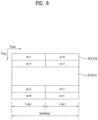
- FIG. 1 shows an exemplary structure of radio frame.
- a radio frame includes 10 subframes.
- a subframe includes two slots in time domain.
- a time for transmitting one subframe is defined as a transmission time interval (TTI).
- TTI transmission time interval
- one subframe may have a length of 1 millisecond (ms)
- one slot may have a length of 0.5 ms .
- One slot includes a plurality of orthogonal frequency division multiplexing (OFDM) symbols in time domain. Since the 3GPP LTE uses the OFDMA in the downlink, the OFDM symbol is for representing one symbol period.
- the OFDM symbol may also be referred to as an SC-FDMA symbol or a symbol period.
- a resource block is a resource allocation unit, and includes a plurality of contiguous subcarriers in one slot.
- the structure of the radio frame is shown for exemplary purposes only. Thus, the number of subframes included in the radio frame or the number of slots included in the subframe or the number of OFDM symbols included in the slot may be modified in various manners .
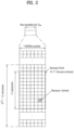
- FIG. 2 shows a resource grid for one downlink slot.
- a downlink slot includes a plurality of OFDM symbols in time domain. It is described-herein that one downlink slot includes 7 OFDM symbols, and one resource block (RB) includes 12 subcarriers in frequency domain as an example. However, the present invention is not limited thereto.
- Each element on the resource grid is referred to as a resource element (RE) .
- One RB includes 12x7 REs.
- the number N DL of RBs included in the downlink slot depends on a downlink transmit bandwidth.
- the structure of an uplink slot may be same as that of the downlink slot.
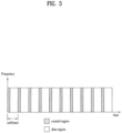
- FIG. 3 shows an exemplary structure of downlink structure .
- a maximum of three OFDM symbols located in a front portion of a first slot within a subframe correspond to a control region to be assigned with a control channel.
- the remaining OFDM symbols correspond to a data region to be assigned with a physical downlink shared chancel (PDSCH).
- Examples of downlink control channels used in the 3GPP LTE includes a physical control format indicator channel (PCFICH), a physical downlink control channel (PDCCH), a physical hybrid ARQ indicator channel (PHICH), etc.
- the PCFICH is transmitted at a first OFDM symbol of a subframe and carries information regarding the number of OFDM symbols used for transmission of control channels within the subframe.
- the PHICH is a response of uplink transmission and carries an HARQ acknowledgment (ACK)/negative-acknowledgment (NACK) signal.
- Control information transmitted through the PDCCH is referred to as downlink control information (DCI).
- the DCI includes uplink or downlink scheduling information or includes an uplink transmit (Tx) power control command for arbitrary UE groups.
- the CCE is a logical allocation unit used to provide the PDCCH with a coding rate based on a state of a radio channel.
- the CCE corresponds to a plurality of resource element groups (REGs).
- a format of the PDCCH and the number of bits of the available PDCCH are determined according to a correlation between the number of CCEs and the coding rate provided by the CCEs.
- the BS determines a PDCCH format according to a DCI to be transmitted to the UE, and attaches a cyclic redundancy check (CRC) to control information.
- the CRC is masked with a unique identifier (referred to as a radio network temporary identifier (RNTI)) according to an owner or usage of the PDCCH.
- RNTI radio network temporary identifier
- a unique identifier (e.g., cell-RNTI (C-RNTI)) of the UE may be masked to the CRC.
- C-RNTI cell-RNTI
- a paging indicator identifier (e.g., paging-RNTI (P-RNTI)) may be masked to the CRC.
- P-RNTI paging-RNTI
- SIB system information block
- SI-RNTI system information RNTI
- RA-RNTI random access-RNTI
- PDCCH format Number of CCEs ( n ) Number of REGs Number of PDCCH bits 0 1 9 72 1 2 18 144 2 4 36 288 3 8 72 576
- CCEs are numbered and used consecutively, and, to simplify the decoding process, a PDCCH with a format consisting of n CCEs may only start with a CCE with a number equal to a multiple of n.
- the number of CCEs used for transmission of a particular PDCCH is determined by the base station according to the channel conditions. For example, if the PDCCH is intended for a UE with a good downlink channel (e.g. close to the base station), then one CCE is likely to be sufficient. However, for a UE with a poor channel (e.g. near the cell border) then eight CCEs may be required in order to achieve sufficient robustness.
- the power level of a PDCCH may be adjusted to match the channel conditions.
- LTE Long Term Evolution
- the approach adopted for LTE is to define for each UE a limited set of CCE locations where a PDCCH may be placed.
- the set of CCE locations in which the UE may find its PDCCHs can be considered as a 'search space'.
- the search space is a different size for each PDCCH format.
- separate dedicated (UE-specific) and common search spaces are defined, where a dedicated search space is configured for each UE individually, while all UEs are informed of the extent of the common search space. Note that the dedicated and common search spaces may overlap for a given UE.
- the UE In order to keep under control the computational load arising from the total number of blind decoding (BD) attempts, the UE is not required to search for all the defined DCI formats simultaneously. Typically, in the dedicated search space, the UE will always search for Formats 0 and 1A, which are both the same size and are distinguished by a flag in the message. In addition, a UE may be required to receive a further format (i.e. 1, 1B or 2, depending on the PDSCH transmission mode configured by the base station). In the common search space the UE will search for Formats 1A and 1C.
- a further format i.e. 1, 1B or 2
- the UE may be configured to search for Format 3 or 3A, which have the same size as formats 0 and 1A, and may be distinguished by having the CRC scrambled by a different (common) identity, rather than a UE-specific one.
- the transmission mode for configuring the multi-antenna technique and the information content of the different DCI formats are listed below.
- the UE would be required to carry out a maximum of 44 BDs in any subframe. This does not include checking the same message with different CRC values, which requires only a small additional computational complexity.
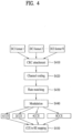
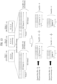
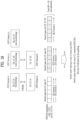
- FIG. 4 is a flowchart illustrating a process of constituting a PDCCH at a base station (BS).
- the BS generates control information according to a DCI format.
- the BS may select one from among a plurality of available DCI formats (DCI formats 1, 2, ..., and N) according to control information to be transmitted to a UE.
- DCI formats 1, 2, ..., and N available DCI formats
- a Cyclic Redundancy Check (CRC) for error detection is attached to the control information generated according to each DCI format.
- the CRC is masked with a Radio Network Temporary Identifier (RNTI) according to an owner or usage of a PDCCH.
- RNTI Radio Network Temporary Identifier
- the PDCCH is CRC-scrambled with an identifier (e.g., an RNTI) .
- Table 3 shows an example of identifiers masked to the PDCCH.
- Type Identifier Description UE-specific C-RNTI, temporary C-RNTI, semi-persistent C-RNTI used for a unique UE identification Common P-RNTI used for paging message SI-RNTI used for system information RA-RNTI used for random access response
- the PDCCH carries control information for a specific UE and, if the other RNTI is used, the PDCCH carries common control information received by all UEs within a cell.
- channel coding is performed with respect to the control information to which the CRC is attached so as to generate coded data.
- rate matching according to a CCE aggregation level assigned to a PDCCH format is performed.
- the coded data is modulated so as to generate modulation symbols.
- the CCE aggregation level of the modulation symbols constituting one PDCCH may be any one of 1, 2, 4 and 8.
- the modulation symbols are mapped to physical Resource Elements (RE).
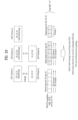
- FIG. 5 is a flowchart illustrating a method of processing a PDCCH at a user equipment (UE).
- UE user equipment
- step S510 the UE demaps physical REs from CCEs.
- step S520 since the UE does not know the CCE aggregation level of the received PDCCH, the UE performs demodulation at each CCE aggregation level.
- step S530 the UE performs rate dematching with respect to the demodulated data. Since the UE does not know the DCI format (or DCI payload size) of the received control information, rate dematching is performed with respect to DCI formats (or DCI payload sizes).
- step S540 channel decoding is performed with respect to the rate-dematched data according to a code rate and a CRC is checked so as to detect errors.
- step S550 the UE which detects its own PDCCH removes the CRC from the decoded data so as to acquire control information.
- a plurality of PDCCHs for a plurality of UEs may be transmitted within a control region of the same subframe.
- the BS does not provide the UE with information indicating where the PDCCH is located in the control region. Accordingly, the UE monitors a set of PDCCH candidates within the subframe and finds its own PDCCH.
- the term "monitoring" means that the UE attempts to decode the received PDCCH candidates according to respective DCI formats. This is referred to as blind decoding (blind detection).
- blind decoding blind detection
- the UE simultaneously performs identification of the PDCCH transmitted to the UE and decoding of the control information transmitted through the corresponding PDCCH. For example, in the case where the PDCCH is demasked using the C-RNTI, no CRC error detection means that the UE detects its own PDCCH.
- the number of DCI formats is set to be less than the number of types of control information transmitted using the PDCCH.
- the DCI format includes a plurality of different fields. The type of the field, the number of fields, and the bit number of each field varies according to the DCI format. In addition, the size of the control information matched to the DCI format varies according to the DCI format. A certain DCI format may be used for transmission of two types of control information.
- Table 4 shows an example of control information transmitted by DCI Format 0.
- the lengths in bits of the following fields are exemplary and nonlimiting.
- Field bit (s) (1) Flag for format0/format1A differentiation 1 (2) Hopping flag 1 (3) Resource block assignment and hopping resource log 2 N RB UL N RB UL + 1 / 2 Allocation (4) Modulation and coding scheme and redundancy Version 5 (5) New data indicator 1 (6) TPC command for scheduled PUSCH 2 (7) Cyclic shift for DM RS 3 (8) UL index (TDD) 2 (9) CQI request 1
- FIG. 7 is a diagram showing a Carrier Aggregation (CA) communication system.
- CA Carrier Aggregation
- a plurality of uplink/downlink Component Carriers may be aggregated so as to support a wider uplink/downlink bandwidth.
- the CCs may be contiguous or non-contiguous in a frequency region.
- the bandwidths of the CCs are independently set.
- Asymmetric CA in which the number of UL CCs and the number of DL CCs are different is also possible.
- the control information may be set to be transmitted/received only through a specific CC.
- Such a specific CC may be referred to as a primary CC and the remaining CCs may be referred to as secondary CCs.
- PDCCH monitoring DL CC can be replaced with equivalent terms such as a monitoring carrier, a monitoring cell, a serving carrier, a serving cell.
- a PDCCH for a specific carrier is transmitted only via the corresponding carrier.
- a PDCCH for DL CC0/UL CC0 is transmitted only via DL CC0.
- a PDCCH search space for DL CC0/UL CC0 is present in DL CC0. That is, a PDCCH search space is constituted per carrier and each PDCCH search space is transmitted only via the corresponding DL CC.
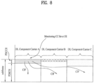
- the monitoring DL CC must transmit not only a PDCCH associated with the monitoring DL CC but also PDCCHs associated with the other carriers. That is, the monitoring DL CC (DL CC A) must transmit all PDCCHs associated with DL CC A, DL CC B and DL CC C. Accordingly, the monitoring DL CC (DL CC A) must include a PDCCH search space associated with DL CC A, a PDCCH search space associated with DL CC B and a PDCCH search space associated with DL CC C.
- PDCCH blocking means that PDCCH scheduling for the corresponding carrier is limited due to limited PDCCH resources. For example, if a plurality of PDCCH search spaces is defined in one carrier, available resources of the PDCCH search space corresponding to each carrier may be limited due to limited PDCCH resources and thus a PDCCH assignment location may be limited or PDCCH assignment may be impossible.
- the PDCCH search space may be newly defined differently from the conventional method. That is, the PDCCH search space may be newly defined to suit management of cross-CC scheduling. For example, the PDCCH search space may be defined over a plurality of carriers.
- the PDCCH search space may be newly defined, backward compatibility with the conventional system (e.g., LTE) is problematic.
- the payload size of the conventional DCI varies according to the carrier band even in the same format, the DCI structure needs to be changed in order to define DCIs within the unified PDCCH search space.
- the present invention proposes a method of solving PDCCH blocking and reducing the number of times that blind decoding is performed on the assumption that the PDCCH search space is defined on a per carrier basis.
- the present invention proposes a method of constituting search spaces for blind decoding if a plurality of CCs is aggregated and cross-CC scheduling is possible.
- Cross-CC scheduling may be performed using CIF inserted into a PDCCH.
- the transmission modes of the aggregated CCs may be independently set and the bandwidths of the CCs may be assigned per CC and thus may be the same or different from each other.
- one or a plurality of DL CCs may be set to a PDCCH monitoring DL CC for the UE (group).
- the PDCCH monitoring DL CC is arbitrarily defined in order to indicate a DL CC used to transmit a plurality of PDCCH search spaces corresponding to carriers upon cross-CC scheduling.
- the PDCCH monitoring DL CC may be replaced with other equivalent terms.
- the term "PDCCH monitoring DL CC" can be replaced with equivalent terms such as a monitoring carrier, a monitoring cell, a serving carrier, a serving cell.
- PDSCH scheduling of DL CCs is shown in the drawings, the present invention is equally applicable to PUSCH scheduling of UL CCs linked with DL CCs.
- a CCE aggregation level of 1 is shown in the drawings, the present invention is equally or similarly applicable to the case where the CCE aggregation level has other values (e.g., 2, 4, or 8).
- BDs for two DCI formats per PDCCH candidate can be performed similar to the conventional LTE system with respect to all cases in the present invention, BDs for one or three or more DCI formats per PDCCH candidate may be performed.
- the present invention is equally or similarly applicable to asymmetric CA in which the number of DL CCs and the number of UL CCs are different.
- the present invention is equally or similarly applicable to the case where DL CCs and UL CCs are linked in many-to-one correspondence or one-to-many correspondence.
- search spaces having control information having the same size are shared.
- search spaces having control information having the same size are aggregated as opposed to being divided on a per carrier basis. Accordingly, monitoring of control information having the same size in the control information associated with carriers may be performed within the same unified search space.
- search spaces for control information having different sizes are divided on a per carrier basis. Accordingly, monitoring of control information having different sizes in the control information associated with carriers is performed only within the search space corresponding to the corresponding carrier.
- the sizes of the search spaces for monitoring the control information may be set to be large. Accordingly, it is possible to increase freedom in control channel scheduling and to solve control channel blocking.
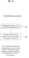
- FIG. 9 is a diagram showing a method of transmitting a control channel to a specific UE at a BS.
- the BS constitutes a plurality of search spaces (S910).
- Each search space includes a plurality of control channel candidates and is defined per carrier (e.g., CC).
- the definition of the search spaces per CC may be performed according to the PDCCH search space constitution method of the conventional LTE system.
- a parameter e.g., a hashing pattern, a location, a size, etc.
- a parameter for a search space per CC may be obtained by a combination of a parameter for a PDCCH search space of the conventional LTE system and a CIF value.
- the plurality of search spaces includes a UE-specific search space or a common search space and preferably includes a UE-specific search space.
- the control channel includes a PDCCH, and a control channel candidate includes a PDCCH candidate.
- the control channel carries a variety of control information and a variety of control information formats is present according to the type/content of the control information.
- the BS transmits the control channel for the specific UE via the plurality of search spaces (S920).
- the control channel (or the control information) may carry an identifier in order to indicate the specific UE.
- the identifier includes an RNTI, e.g., C-RNTI or SPS-RNTI.
- the control channel (or the control information) may be scrambled using the identifier.
- the BS may transmit the PDCCH that is CRC-scrambled with the C-RNTI to the UE.
- cross-carrier scheduling may be performed using the CIF within the control channel.
- the CIF may have a representative value (e.g., DL CC indication value) indicating a linked DL/UL CC pair or a value separately indicating DL CC or UL CC.
- the CIF may be represented by an absolute index or a relative index (e.g., offset).
- the search spaces may be constituted per linked DL/UL CC pair, DL CC or UL CC.
- the search spaces may be contiguous in a logical index or may be independently set and the search spaces may partially or wholly overlap each other.
- the size of the search space corresponding to each carrier (or CIF) may be determined in proportion to a maximum number of PDCCHs transmittable via the search space or may be given weights or all the sizes of the search spaces may be the same.
- One control information format per DL CC or UL CC may be set or two or more control information formats per DL CC or UL CC may be set, in the search space corresponding to each carrier (or CIF).
- a DL/UL common control information format such as DCI Format 0/1A of the LTE system may be set in the search spaces.
- the type of the control information format set in the search spaces may vary according to the transmission mode (e.g., a MIMO mode).
- search spaces When the search spaces are constructed, if control channel formats having the same size (or control information having the same size irrespective of the format) are present in the plurality of search spaces, the search spaces of the corresponding control channel formats are shared. If the number of search spaces constituted on one carrier is M (M ⁇ 2), N (N ⁇ M) search spaces may be shared. The sharing/non-sharing of the search spaces or the number of search spaces may be determined per control channel format (or per control information size irrespective of the format). Accordingly, if the search spaces are constituted per carrier but the control formats having the same size (or the control information having the same size irrespective of the format) are present, the search spaces are unified.
- a control channel for the UE that is related with one of carriers (or CIF) corresponding to the shared N search spaces may be transmitted via any one of the N search spaces. That is, control channel candidates having the same size over the N search spaces may be transmitted via any one of the N search spaces. In this case, control channel candidates having the same size are discriminated using CIF (Carrier Indicator Field) values.
- CIF Carrier Indicator Field
- the BS may constitute the search spaces per CC and compare the DCI (format) sizes for all the CCs. If DCIs (formats) having the same size are present, the BS may unify the search spaces of the DCIs (formats) so as to constitute an extended search space. Accordingly, PDCCHs for the DCIs (formats) having the same size may be transmitted via any PDCCH candidate within the extended search space, instead of via respective search spaces. In this case, PDCCH candidates within the extended search space are discriminated using CIF (Carrier Indicator Field) values.
- CIF Carrier Indicator Field
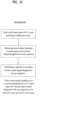
- FIG. 10 is a diagram showing an example of processing a control channel (e.g., a PDCCH) at a UE.
- a control channel e.g., a PDCCH
- the process of FIG. 10 corresponds to the process of FIG. 9 and the detailed description refers to the description of FIG. 9 .
- the UE receives a plurality (M: M ⁇ 2) of search spaces (S1110). Each search space is defined per carrier. Thereafter, the UE monitors control channel candidates within the search spaces in order to find a control channel assigned to the UE (S1120). The monitoring process includes blind decoding each of the control channel candidates. Thereafter, the UE may perform an operation according to the control channel assigned to the UE (S1130).
- control channel candidates have the same information size over N (N ⁇ M) search spaces
- a control channel for the UE that is related with one of carriers (or CIF) corresponding to the N search spaces may be received via any one of the N search spaces.
- the UE monitors control channel candidates on an assumption that the control channel candidates having the same information size can be received via any one of the N search spaces.
- the control channel candidates having the same information size are discriminated using CIF (Carrier Indicator Field) values.
- control channel candidates have different information sizes per search spaces
- the control channel for the specific UE may be received only via the search space corresponding to the corresponding carrier (or CIF). That is, control channel candidates with a same CIF are transmitted via only one search space corresponding to the CIF.
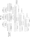
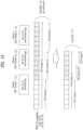
- FIG. 11A shows an example of constituting search spaces according to an embodiment of the present invention.
- three DL CCs are aggregated and the transmission modes of DL CCs are set to 1, 3 and 4.
- DL CC #1 is a PDCCH monitoring DL CC.
- the number of times that BD is performed per DCI format is the same (BD is performed with respect to six PDCCH candidates similar to the LTE system) in the present example, the number of times that BD is performed may vary according to DCI formats.
- MaxBD maximum BD times
- the BD for DCI Formats 1, 2A and 2 is performed via the search spaces including six PDCCH candidates.
- the search space for DCI Format 1A may be composed of 12 PDCCH candidates and the search space for each of DCI Formats 1, 2A and 2 may be composed of four PDCCH candidates.
- the number of PDCCH candidates for DCI Format 1A may be 9 and the search space for each of DCI Formats 1, 2A and 2 may include three PDCCH candidates.
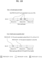
- FIG. 11B shows an example of performing PDCCH transmission and BD in the case of search space sharing.
- search spaces corresponding to three carriers or CIF
- Each search space may correspond to any one of a linked DL CC-UL CC pair, a DL CC or a UL CC.
- the sizes of three search spaces may be different and the CCE aggregation levels of the PDCCH candidates in each search space may be different.
- a search space for CC #1 may have a CCE aggregation level of 1 and a search space for CC #2/#3 may have a CCE aggregation level of 2, 4 or 8.
- Case 2 of FIG. 11B shows the case where the search spaces are partially shared.
- the search spaces for CC #1/CC #3 are shared. That is, the PDCCH candidates of the search spaces for CC #1/CC #3 have the same DCI payload size and the PDCCH candidates of the search space for CC #2 have a different DCI payload size other than the PDCCH candidates of the search spaces for CC #1/CC #3.
- the UE performs BD only with respect to the PDCCH candidates of the search spaces for CC #2.
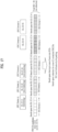
- FIG. 12 shows a method of constituting PDCCH search spaces if the transmission modes of DL CCs are set to 1, 1 and 4 under the same condition as FIG. 11A .
- DCIF DL CC #1
- the search spaces for DCI Formats 1A, 1 and 2 may be respectively composed of 12, 8 and 4 PDCCH candidates.
- the number of PDCCH candidates for DCI Formats 1A, 1 and 2 may be 9, 6 and 3, respectively.
- FIG. 13 is a diagram showing another example of constituting PDCCH search spaces.
- a plurality of DL CCs may be set to a PDCCH monitoring DL CC set. If the number of CCs within the PDCCH monitoring CC set is L, as shown in FIG. 13 , a method of limiting (MaxBD)/L to a maximally allowable number of times that BD is performed per monitoring CC or applying different weights to monitoring CCs (e.g., anchor DL CCs) (that is, differently limiting the maximally allowable number of times that BD is performed per monitoring CC) may be applied.
- the method of constituting the search spaces according to the number of monitoring CCs may be set by the BS in advance or may be automatically set by the UE under the MaxBD limitation.
- the sizes of the search spaces for the DCIs (formats) on the monitoring DL CCs may be set in proportion to the number of DCIs (formats). Accordingly, it is possible to increase a degree of freedom in PDCCH scheduling and to solve PDCCH blocking.
- a PDCCH transmitted through a specific CC which performs resource assignment with respect to a data channel of the corresponding CC
- a PDCCH which performs resource assignment with respect to a data channel of a CC other than the corresponding CC
- a cross-CC PDCCH in order to reduce BD times on a specific CC and preferably on a PDCCH monitoring DL CC, both the search space for the self-CC PDCCH and the search space for the cross-CC PDCCH may be reduced.
- the search space for the cross-CC PDCCH is reduced more than the search space for the self-CC PDCCH.
- the search space for the self-CC PDCCH may not be reduced and only the search space for the cross-CC PDCCH may be reduced.
- the search space for the self-CC PDCCH is not reduced and only the search space for the cross-CC PDCCH is reduced.
- this is only exemplary and the following drawings and description may be applied to the case where the search space for the self-CC PDCCH and the search space for the cross-CC PDCCH are reduced, the case where the search space for the cross-CC PDCCH is reduced more than the search space for the self-CC PDCCH, etc.
- FIG. 14 shows an example of constituting PDCCH search spaces if the transmission modes of DL CCs are 1, 3 and 4 in a state in which three DL CCs are aggregated. For convenience, it is assumed that the bandwidths of all CCs are the same and DL CC #1 is set to a PDCCH monitoring DL CC.
- the sizes of DCI Formats 1A for three CCs are the same and DCI Formats 1, 2A and 2 respectively have unique sizes. Accordingly, the search spaces for DCI Format 1A may be shared.
- MaxBD is reduced to 24, the search space for the self-CC PDCCH may be maintained and the search space for the cross-CC PDCCH may be reduced.
- a ratio of the size of the search space of the self-CC PDCCH to the size of the search space of the cross-CC PDCCH per CC may be set to 2:1.
- DCI Format 1 used only in the DL CC #1 (monitoring) may have six PDCCH candidates and DCI Formats 2A and 2 used only in DL CC #2 and #3 (non-monitoring) may have three PDCCH candidates.
- the sizes of DCI Formats 1A for three CCs are the same, the sizes of DCI Formats 1 for two CCs are the same, and only DCI Format 2 has a unique size. Accordingly, three search spaces for DCI Format 1A may be shared and two search spaces for DCI Format 1 may be shared.
- the search space for the self-CC PDCCH may be maintained and the search space for the cross-CC PDCCH may be reduced.
- a ratio of the size of the search space of the self-CC PDCCH to the size of the search space of the cross-CC PDCCH per CC may be set to 2:1.
- the search space of the self-CC PDCCH includes 12 PDCCH candidates and the search space of the cross-CC PDCCH per non-monitoring CC includes six PDCCH candidates.
- the DCI format 2 used only in the DL CC #3 (non-monitoring) may have three PDCCH candidates.
- a plurality of control information e.g., DCI
- DCI size unification or DCI size matching
- DCI size matching may be performed such that the DCI formats have the same size.
- DCI size matching may be performed only in the case where a difference between the sizes of DCIs is equal to or less than a threshold.
- DCI size matching may be performed only in the case where a difference between the sizes of DCIs is equal to or less than 3 bits.
- DCI size matching may be performed using bit padding.
- a padding bit (stream) may have a specific pattern or a specific value (e.g., 0).
- the padding bit (stream) may have a value indicating a DCI format or a specific value for error checking.
- the search spaces therefor may be shared as described in Embodiment 1. Accordingly, the search spaces may be extended in proportion to the number of DCIs (formats) grouped into the single size.
- the use/non-use of the present method and the parameter of the present method may be set by the BS per UE, UE group or cell or may be automatically set by the UE within the maximally allowable number (MaxBD) of times that BD is performed.
- MaxBD maximally allowable number
- FIG. 16 is a diagram showing an example of constituting search spaces for BD of a PDCCH, if the transmission modes of DL CCs are 1, 3 and 4 in a state in which three DL CCs are aggregated. It is assumed that the bandwidth of DL CC #1 is equal to that of DL CC #2, but is different from that of DL CC #3, and DL CC #1 is set to a PDCCH monitoring DL CC. Accordingly, the sizes of DCI Format 1A for two CCs (DL CC #1 and #2) are the same (Unified F1) and DCI Format 1A (Format 3-1A) for DL CC #3 and DCI Formats 1, 2A and 2 respectively have unique sizes. In the present example, it is assumed that a threshold for DCI size matching is set to 3 bits.
- FIG. 16 shows the case where the DCI size unification (or DCI size matching) is performed if the maximum number MaxBD of times that BD is performed is reduced.
- this is only exemplary and the DCI size unification (or DCI size matching) of the present invention is applicable irrespective of whether or not MaxBD is reduced.
- DCI size matching to a single size may be performed even with respect to three or more DCIs in which a difference between DCI sizes is equal to or below a given threshold.
- DCI size matching e.g., bit padding
- CCs for which DCI formats are set within a DCI group may be made exclusive. If a plurality of DCI groups is possible, bit padding may be preferentially performed with respect to a group having a larger number of DCI formats or a group having a smaller sum of differences with a maximum DCI format size.
- each search space constituted per DL/UL CC pair, DL CC or UL CC may be determined in proportion to the maximum number of PDCCHs transmittable via the search space or may be given weights.
- a plurality of DCI formats may be set.
- a DL/UL common DCI format may be set.
- a search space for a DL CC and a search space for a UL CC may be independently constituted or [Scheme 2] one search space may be constituted per linked DL/UL CC pair.
- FIG. 17 shows an asymmetric CC aggregation case in which three DL CCs and two UL CCs are aggregated.
- a search space for each DL CC and a search space for each UL CC may be independently constituted.
- DCIs (formats) having the same size irrespective of DL/UL may share search spaces corresponding to CCs as described in Embodiment 1.
- Embodiments 2 and 3 may be applied together/separately.
- cross-CC scheduling may be set to be performed with respect to a limited number of DL/UL CC groups.
- the setting of the cross-CC scheduling may vary according to PDCCH monitoring DL CCs. If a plurality of PDCCH monitoring DL CCs is used, DCIs (formats) having the same size share corresponding search spaces on the respective monitoring CCs. If the DCIs (formats) having the same size are present between the monitoring CCs, the corresponding search spaces may be shared. The search spaces may be shared between the monitoring CCs without limitation in setting of cross-CC scheduling.
- the sizes of the search spaces shared between the DCIs (formats) having the same size may be further reduced. For example, if the sizes of the plurality of DCIs (formats) are the same, only a part (one) of the search spaces for the DCIs (formats) may be assigned as the search space shared between the DCIs (formats) or a plurality of search spaces for DCIs (formats) is collectively reduced so as to constitute one shared search space.
- the ratio of the size of the search space shared between the DCIs (formats) having the same size may be set in proportion to the number of DCIs (formats) sharing the corresponding space.
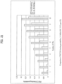
- Figures 21 and 22 show PDCCH blocking probability according to SS sharing when 2 CCs are aggregated per UE, and BWs of PDCCH CC are 10 MHz, 20 MHz, respectively. As shown in the figures, it is observed that overall PDCCH blocking probability can be largely reduced (more than 25% and 33% reduction in 10 MHz and 20 MHz, respectively) by applying the SS sharing compared to the case of no SS sharing.
- FIG. 23 is a diagram illustrating a base station and a user equipment, which can be applied to the embodiment of the present invention.
- the wireless communication system includes a base station (BS) 110 and a user equipment (UE) 120.
- the base station 110 includes a processor 112, a memory 114, and a radio frequency (RF) unit 116.
- the processor 112 can be configured to implement procedures and/or methods suggested in the present invention.
- the memory 114 is connected with the processor 112 and stores various kinds of information related to the operation of the processor 112.
- the RF unit 116 is connected with the processor 112 and transmits and/or receives a radio signal.
- the user equipment 120 includes a processor 122, a memory 124, and a radio frequency (RF) unit 126.
- the processor 122 can be configured to implement procedures and/or methods suggested in the present invention.
- the memory 124 is connected with the processor 122 and stores various kinds of information related to the operation of the processor 122.
- the RF unit 126 is connected with the processor 122 and transmits and/or receives a radio signal.
- the base station 110 and/or the user equipment 120 may have a single antenna or multiple antennas.
- the embodiments of the present invention have been described based on the data transmission and reception between the base station and the user equipment.
- a specific operation which has been described as being performed by the base station may be performed by an upper node of the base station as the case may be.
- various operations performed for communication with the user equipment in the network which includes a plurality of network nodes along with the base station can be performed by the base station or network nodes other than the base station.
- the base station may be replaced with terms such as a fixed station, Node B, eNode B (eNB), and access point.
- the user equipment may be replaced with terms such as mobile station (MS) and mobile subscriber station (MSS).
- the embodiments according to the present invention can be implemented by various means, for example, hardware, firmware, software, or their combination. If the embodiment according to the present invention is implemented by hardware, the embodiment of the present invention can be implemented by one or more application specific integrated circuits (ASICs) , digital signal processors (DSPs) , digital signal processing devices (DSPDs) , programmable logic devices (PLDs) , field programmable gate arrays (FPGAs) , processors, controllers, microcontrollers, microprocessors, etc.
- ASICs application specific integrated circuits
- DSPs digital signal processors
- DSPDs digital signal processing devices
- PLDs programmable logic devices
- FPGAs field programmable gate arrays
- the embodiment of the present invention may be implemented by a type of a module, a procedure, or a function, which performs functions or operations described as above.
- a software code may be stored in a memory unit and then may be driven by a processor.
- the memory unit may be located inside or outside the processor to transmit and receive data to and from the processor through various means which are well known.
- the present invention can be used in wireless communication apparatuses such as a user equipment, a relay station, a base station and the like.
Landscapes
- Engineering & Computer Science (AREA)
- Signal Processing (AREA)
- Computer Networks & Wireless Communication (AREA)
- Quality & Reliability (AREA)
- Mobile Radio Communication Systems (AREA)
Applications Claiming Priority (4)
| Application Number | Priority Date | Filing Date | Title |
|---|---|---|---|
| US28770009P | 2009-12-17 | 2009-12-17 | |
| US29321110P | 2010-01-08 | 2010-01-08 | |
| US29935510P | 2010-01-29 | 2010-01-29 | |
| PCT/KR2010/009076 WO2011074914A2 (en) | 2009-12-17 | 2010-12-17 | Apparatus and method of avoiding control channel blocking |
Publications (3)
| Publication Number | Publication Date |
|---|---|
| EP2514238A2 EP2514238A2 (en) | 2012-10-24 |
| EP2514238A4 EP2514238A4 (en) | 2016-03-09 |
| EP2514238B1 true EP2514238B1 (en) | 2025-06-04 |
Family
ID=44167897
Family Applications (1)
| Application Number | Title | Priority Date | Filing Date |
|---|---|---|---|
| EP10837910.8A Active EP2514238B1 (en) | 2009-12-17 | 2010-12-17 | Apparatus and method of avoiding control channel blocking |
Country Status (10)
| Country | Link |
|---|---|
| US (5) | US8634374B2 (enExample) |
| EP (1) | EP2514238B1 (enExample) |
| JP (4) | JP5597721B2 (enExample) |
| KR (1) | KR101835329B1 (enExample) |
| CN (2) | CN104901778B (enExample) |
| AU (1) | AU2010330967B2 (enExample) |
| CA (1) | CA2784271C (enExample) |
| MX (1) | MX2012006801A (enExample) |
| RU (1) | RU2505945C1 (enExample) |
| WO (1) | WO2011074914A2 (enExample) |
Families Citing this family (65)
| Publication number | Priority date | Publication date | Assignee | Title |
|---|---|---|---|---|
| MX2012006801A (es) | 2009-12-17 | 2012-07-10 | Lg Electronics Inc | Aparato y metodo para evitar bloqueo del canal de control. |
| KR101769371B1 (ko) * | 2010-01-11 | 2017-08-30 | 엘지전자 주식회사 | 크기를 조정한 dci를 이용한 pdcch 송수신 방법 및 장치 |
| BR112012020255B1 (pt) * | 2010-02-11 | 2019-01-15 | Huawei Technologies Co., Ltd. | método, estação de base, ue e sistema para transmissão e recepção de sinalização pdcch |
| EP3742639B1 (en) | 2010-02-15 | 2024-12-11 | Sun Patent Trust | Transmission device and transmission method |
| CN105577342B (zh) | 2010-04-30 | 2018-09-14 | 广东欧珀移动通信有限公司 | 用于共享载波聚合的控制信道的系统和方法 |
| EP2398180A1 (en) * | 2010-06-21 | 2011-12-21 | Panasonic Corporation | Configuration of uplink and downlink grant search spaces in a OFDM-based mobile communication system |
| KR102031031B1 (ko) * | 2011-06-20 | 2019-10-15 | 삼성전자 주식회사 | 무선 통신 시스템에서 시분할 복식 프레임 구성 정보 송수신 방법 및 장치 |
| US9300448B2 (en) * | 2011-07-12 | 2016-03-29 | Broadcom Corporation | Search space for component carrier specific UL/DL configuration |
| EP3410610B1 (en) | 2011-07-25 | 2021-06-23 | LG Electronics Inc. | Method and apparatus for monitoring a wireless link in a wireless communication system |
| CN102291736B (zh) * | 2011-08-08 | 2017-11-24 | 中兴通讯股份有限公司 | 下行控制信道的检测方法、用户设备及基站 |
| US9119120B2 (en) * | 2012-01-23 | 2015-08-25 | Intel Corporation | Network assisted user association and offloading techniques for integrated multi-rat heterogeneous networks |
| US9660783B2 (en) | 2012-03-30 | 2017-05-23 | Lg Electronics Inc. | Method and device for receiving control information in wireless communication system |
| WO2013147566A1 (ko) | 2012-03-30 | 2013-10-03 | 엘지전자 주식회사 | 무선 통신 시스템에서 제어정보 수신 방법 및 장치 |
| CN102711248B (zh) * | 2012-05-11 | 2016-03-30 | 中兴通讯股份有限公司 | 降低控制信道中盲解码计算负载的处理方法、基站及终端 |
| CN104641576B (zh) | 2012-09-06 | 2019-05-10 | 三星电子株式会社 | 用于在非对称多载波通信网络环境中传送下行链路控制信息的方法和装置 |
| US9320032B2 (en) * | 2013-01-03 | 2016-04-19 | Qualcomm Incorporated | ENB PDCCH implementation to avoid ambiguous DCI information |
| US10432370B2 (en) * | 2013-01-14 | 2019-10-01 | Qualcomm Incorporated | Transmission and processing of higher order modulation |
| BR112015016070B1 (pt) | 2013-01-16 | 2023-01-10 | Telefonaktiebolaget L M Ericsson (Publ) | Equipamento de usuário, e, método implementado por um equipamento de usuário |
| JP6298263B2 (ja) * | 2013-09-26 | 2018-03-20 | 株式会社Nttドコモ | 無線基地局、ユーザ端末及び無線通信方法 |
| US9497008B2 (en) * | 2013-09-27 | 2016-11-15 | Apple Inc. | System and method for searching for grants and assignments in a PDCCH |
| US9544892B2 (en) * | 2013-09-27 | 2017-01-10 | Apple Inc. | System and method for searching for a control channel |
| US20150127418A1 (en) * | 2013-11-01 | 2015-05-07 | Facebook, Inc. | Notifying an advertiser of high engagement posts in a social networking system |
| CN104936206A (zh) * | 2014-03-20 | 2015-09-23 | 中兴通讯股份有限公司 | 控制信道的配置、检测方法、装置及系统 |
| CN105188140A (zh) * | 2014-06-10 | 2015-12-23 | 中兴通讯股份有限公司 | 控制信道的配置方法、接收方法、装置及系统 |
| EP3018855B1 (en) | 2014-11-07 | 2019-03-20 | Panasonic Intellectual Property Corporation of America | Physical downlink control channel PDCCH assignment procedure |
| CN104683069B (zh) * | 2015-02-13 | 2018-04-27 | 大唐联仪科技有限公司 | 一种物理下行控制信道pdcch盲检测方法和系统 |
| JP6255642B2 (ja) * | 2015-03-04 | 2018-01-10 | シャープ株式会社 | 移動局装置、基地局装置、および通信方法 |
| US10652768B2 (en) | 2015-04-20 | 2020-05-12 | Qualcomm Incorporated | Control channel based broadcast messaging |
| CN106301671B (zh) * | 2015-05-15 | 2021-01-22 | 中兴通讯股份有限公司 | 下行控制信道的传输方法、配置方法及终端、基站 |
| US11057914B2 (en) * | 2015-07-24 | 2021-07-06 | Lg Electronics Inc. | Downlink control information receiving method and user equipment, and downlink control information transmission method and base station |
| EP3547596B1 (en) * | 2015-08-07 | 2021-09-29 | Panasonic Intellectual Property Corporation of America | Self- and cross-carrier scheduling |
| US11277235B2 (en) * | 2015-11-23 | 2022-03-15 | Qualcomm Incorporated | Techniques for multiplexing or cascading control information and data within a transmission time interval |
| US20170168729A1 (en) * | 2015-12-11 | 2017-06-15 | Netapp, Inc. | Methods and systems for managing resources of a networked storage environment |
| EP3404897B1 (en) | 2016-01-12 | 2021-01-20 | Fujitsu Limited | Wireless communication device, wireless communication system, and wireless communication method |
| CN108463987B (zh) * | 2016-01-12 | 2021-03-16 | 富士通株式会社 | 无线通信装置、无线通信系统和无线通信方法 |
| CN108605360B (zh) * | 2016-01-27 | 2021-10-15 | 高通股份有限公司 | 移动设备中的定时提前值保护 |
| CN107306174B (zh) * | 2016-04-20 | 2021-07-27 | 西安中兴新软件有限责任公司 | 一种用于载波聚合的载波调度的方法、设备和系统 |
| JP6831906B2 (ja) * | 2016-08-30 | 2021-02-17 | エルジー エレクトロニクス インコーポレイティド | 無線通信システムにおける下りリンク制御情報送信方法及び上記方法を利用する装置 |
| ES2740644T3 (es) | 2016-11-02 | 2020-02-06 | Ericsson Telefon Ab L M | Monitorización de espacio de búsqueda en redes de comunicación inalámbrica |
| US11304190B2 (en) * | 2016-11-08 | 2022-04-12 | Qualcomm Incorporated | Search space design and use |
| WO2018173442A1 (ja) * | 2017-03-22 | 2018-09-27 | パナソニック インテレクチュアル プロパティ コーポレーション オブ アメリカ | 基地局および通信方法 |
| CN108923895B (zh) * | 2017-03-23 | 2021-08-13 | 华为技术有限公司 | 信息传输方法、装置及系统 |
| CN108811156B (zh) | 2017-05-04 | 2021-09-17 | 大唐移动通信设备有限公司 | 一种信息传输方法及装置 |
| CN111278137B (zh) * | 2017-06-16 | 2021-01-05 | 华为技术有限公司 | 上行资源的授权方法、装置及系统 |
| JP7330599B2 (ja) * | 2017-08-10 | 2023-08-22 | 株式会社Nttドコモ | 端末、無線通信方法、基地局及びシステム |
| CN111194566B (zh) * | 2017-08-10 | 2023-11-14 | 株式会社Ntt都科摩 | 用户终端以及无线通信方法 |
| GB2566990B (en) * | 2017-09-29 | 2020-08-05 | Tcl Communication Ltd | Improvements in or relating to transmission without grant in New Radio |
| US11553469B2 (en) | 2017-11-14 | 2023-01-10 | Idac Holdings, Inc. | Methods for physical downlink control channel (PDCCH) candidate determination |
| PT3739996T (pt) * | 2018-01-11 | 2024-01-12 | Ntt Docomo Inc | Terminal de utilizador e método de comunicações sem fios |
| CN110166191B (zh) * | 2018-02-11 | 2021-01-08 | 维沃移动通信有限公司 | 一种搜索空间的监听信息的确定方法及装置 |
| CN110324109B (zh) * | 2018-03-29 | 2021-11-26 | 北京紫光展锐通信技术有限公司 | Pdsch速率匹配方法、装置、用户终端及计算机可读存储介质 |
| US11089582B2 (en) * | 2018-04-05 | 2021-08-10 | Huawei Technologies Co., Ltd. | Method and system for downlink control information payload size determination |
| EP3780799B1 (en) * | 2018-04-05 | 2024-03-13 | Ntt Docomo, Inc. | User terminal and wireless base station |
| CN113783671B (zh) * | 2018-05-11 | 2022-12-27 | 华为技术有限公司 | 通信方法、终端设备和网络设备 |
| US12295002B2 (en) * | 2018-07-20 | 2025-05-06 | Qualcomm Incorporated | Multi-carrier scheduling and search space activation |
| CN110830216B (zh) * | 2018-08-10 | 2021-03-30 | 华为技术有限公司 | 确定载波聚合下监控pdcch候选数目的方法和装置 |
| WO2020145618A1 (ko) * | 2019-01-10 | 2020-07-16 | 엘지전자 주식회사 | 무선 통신 시스템에서 초기 접속 절차에 기반하여 단말 및 기지국 간 하향링크 제어 정보의 송수신 방법 및 이를 지원하는 장치 |
| WO2020145611A1 (ko) * | 2019-01-10 | 2020-07-16 | 엘지전자 주식회사 | 무선 통신 시스템에서 불연속 수신 모드 설정에 기반하여 단말 및 기지국 간 하향링크 제어 정보의 송수신 방법 및 이를 지원하는 장치 |
| US11233601B2 (en) * | 2019-04-15 | 2022-01-25 | Mediatek Singapore Pte. Ltd. | Method and apparatus for downlink control information size alignment in mobile communications |
| US11723036B2 (en) * | 2019-11-22 | 2023-08-08 | Qualcomm Incorporated | Dynamic search spaces |
| CN113473611B (zh) * | 2020-03-31 | 2024-09-06 | 维沃移动通信有限公司 | 资源调度方法、装置及ue |
| CN113543318B (zh) * | 2020-04-15 | 2024-09-10 | 大唐移动通信设备有限公司 | 一种载波确定及指示方法、设备、装置、介质 |
| WO2022026449A1 (en) * | 2020-07-28 | 2022-02-03 | Yunjung Yi | Control channel repetition configuration |
| US11962407B2 (en) * | 2020-09-24 | 2024-04-16 | Qualcomm Incorporated | Blind decoding counting for repetition-based physical downlink control channel candidates |
| WO2022137569A1 (ja) * | 2020-12-25 | 2022-06-30 | 株式会社Nttドコモ | 端末、基地局及び無線通信方法 |
Citations (1)
| Publication number | Priority date | Publication date | Assignee | Title |
|---|---|---|---|---|
| WO2010131926A2 (ko) * | 2009-05-14 | 2010-11-18 | 엘지전자 주식회사 | 다중 반송파 시스템에서 제어채널을 모니터링하는 장치 및 방법 |
Family Cites Families (35)
| Publication number | Priority date | Publication date | Assignee | Title |
|---|---|---|---|---|
| US6493331B1 (en) | 2000-03-30 | 2002-12-10 | Qualcomm Incorporated | Method and apparatus for controlling transmissions of a communications systems |
| CN100574177C (zh) * | 2005-06-23 | 2009-12-23 | 上海原动力通信科技有限公司 | 多载波hsdpa控制信道的分配方法和分组数据传输方法 |
| US8045518B2 (en) | 2007-03-23 | 2011-10-25 | Innovative Sonic Limited | Method of deactivating high-speed downlink operation in CELL—FACH state for a wireless communications system and related apparatus |
| KR101448309B1 (ko) * | 2007-09-28 | 2014-10-08 | 엘지전자 주식회사 | 무선통신 시스템에서 하향링크 제어채널 모니터링 방법 |
| JP2009089020A (ja) | 2007-09-28 | 2009-04-23 | Fujitsu Ltd | 通信装置、保守システム、保守方法、及びコンピュータプログラム |
| CN103414533B (zh) * | 2007-09-28 | 2016-08-10 | Lg电子株式会社 | 在无线通信系统中检测控制信息的方法及设备 |
| RU2501187C2 (ru) | 2007-10-29 | 2013-12-10 | Панасоник Корпорэйшн | Устройство базовой станции беспроводной связи, и устройство мобильной станции беспроводной связи, и способ выделения канала управления |
| KR101459147B1 (ko) * | 2008-02-04 | 2014-11-10 | 엘지전자 주식회사 | 무선통신 시스템에서 전송 파워 제어 명령 전송 방법 |
| US8239721B2 (en) * | 2008-04-25 | 2012-08-07 | Interdigital Patent Holdings, Inc. | HARQ process utilization in multiple carrier wireless communications |
| US9853793B2 (en) * | 2008-07-30 | 2017-12-26 | Lg Electronics Inc. | Method and apparatus of transmitting control information in wireless communication system |
| KR101557676B1 (ko) * | 2008-10-31 | 2015-10-06 | 삼성전자주식회사 | 이동무선 통신시스템의 하향링크 제어채널의 페이로드 크기결정장치 및 방법 |
| ES2534787T3 (es) * | 2008-12-02 | 2015-04-28 | Samsung Electronics Co., Ltd | Recepción de asignaciones de planificación en múltiples anchos de banda operativos |
| WO2010068069A2 (ko) * | 2008-12-11 | 2010-06-17 | 엘지전자 주식회사 | 다중 반송파 시스템에서 제어채널 검출방법 |
| WO2010088536A1 (en) * | 2009-01-30 | 2010-08-05 | Interdigital Patent Holdings, Inc. | Method and apparatus for component carrier aggregation in wireless communications |
| US20100254329A1 (en) * | 2009-03-13 | 2010-10-07 | Interdigital Patent Holdings, Inc. | Uplink grant, downlink assignment and search space method and apparatus in carrier aggregation |
| US8934417B2 (en) * | 2009-03-16 | 2015-01-13 | Google Technology Holdings LLC | Resource allocation in wireless communication systems |
| US8441996B2 (en) * | 2009-04-02 | 2013-05-14 | Lg Electronics Inc. | Method and apparatus for monitoring control channel in multiple carrier system |
| EP3745616A1 (en) * | 2009-04-24 | 2020-12-02 | LG Electronics Inc. | Method and apparatus for transmitting and receiving control signal for merging carriers in transmission |
| US8989208B2 (en) * | 2009-04-30 | 2015-03-24 | Qualcomm Incorporated | PDCCH search space design for LTE-A multi-carrier operation |
| WO2010131927A2 (ko) * | 2009-05-14 | 2010-11-18 | 엘지전자 주식회사 | 다중 반송파 시스템에서 제어채널을 모니터링하는 장치 및 방법 |
| US8660023B2 (en) * | 2009-06-02 | 2014-02-25 | Blackberry Limited | System and method for reducing blind decoding for carrier aggregation |
| ES2657223T3 (es) * | 2009-06-15 | 2018-03-02 | Guangdong Oppo Mobile Telecommunications Corp., Ltd. | Procedimiento y sistema para compartir un canal de control para agregación de portador |
| EP2445272A4 (en) * | 2009-06-16 | 2014-08-06 | Sharp Kk | MOBILE STATION DEVICE, BASE STATION DEVICE, RADIO COMMUNICATION METHOD, AND COMMUNICATION SOFTWARE |
| EP2449809A1 (en) * | 2009-07-03 | 2012-05-09 | Nokia Siemens Networks Oy | Extension of physical downlink control channel coverage |
| CN101998504B (zh) * | 2009-08-10 | 2013-04-10 | 电信科学技术研究院 | 多载波聚合系统中下行信息的传输方法及装置 |
| US9351293B2 (en) * | 2009-09-11 | 2016-05-24 | Qualcomm Incorporated | Multiple carrier indication and downlink control information interaction |
| CA2775313A1 (en) * | 2009-09-25 | 2011-03-31 | Research In Motion Limited | System and method for multi-carrier network operation |
| EP2481249B1 (en) * | 2009-09-25 | 2018-12-26 | BlackBerry Limited | Multi-carrier network operation |
| US8433251B2 (en) * | 2009-09-28 | 2013-04-30 | Qualcomm Incorporated | Control information signaling |
| US9055576B2 (en) * | 2009-10-08 | 2015-06-09 | Qualcomm Incorporated | Uplink resource allocation for LTE advanced |
| KR20110049595A (ko) * | 2009-11-05 | 2011-05-12 | 주식회사 팬택 | 무선 통신 시스템에서 제어 정보를 송신 및 수신하는 방법 및 장치 |
| KR101777416B1 (ko) * | 2009-11-26 | 2017-09-27 | 엘지전자 주식회사 | 반송파 집성 시스템에서 단말의 통신 방법 및 단말 |
| MX2012006801A (es) | 2009-12-17 | 2012-07-10 | Lg Electronics Inc | Aparato y metodo para evitar bloqueo del canal de control. |
| EP2360866A1 (en) * | 2010-02-12 | 2011-08-24 | Panasonic Corporation | Component carrier activation and deactivation using resource assignments |
| US20110267948A1 (en) * | 2010-05-03 | 2011-11-03 | Koc Ali T | Techniques for communicating and managing congestion in a wireless network |
-
2010
- 2010-12-17 MX MX2012006801A patent/MX2012006801A/es active IP Right Grant
- 2010-12-17 AU AU2010330967A patent/AU2010330967B2/en active Active
- 2010-12-17 EP EP10837910.8A patent/EP2514238B1/en active Active
- 2010-12-17 RU RU2012130094/08A patent/RU2505945C1/ru active
- 2010-12-17 US US13/513,072 patent/US8634374B2/en active Active
- 2010-12-17 WO PCT/KR2010/009076 patent/WO2011074914A2/en not_active Ceased
- 2010-12-17 JP JP2012544397A patent/JP5597721B2/ja active Active
- 2010-12-17 CN CN201510187818.3A patent/CN104901778B/zh active Active
- 2010-12-17 CA CA2784271A patent/CA2784271C/en active Active
- 2010-12-17 CN CN201080057739.6A patent/CN102668646B/zh active Active
- 2010-12-17 KR KR1020127005789A patent/KR101835329B1/ko active Active
-
2013
- 2013-11-15 US US14/081,384 patent/US9554377B2/en active Active
-
2014
- 2014-08-11 JP JP2014163915A patent/JP5869636B2/ja active Active
-
2016
- 2016-01-07 JP JP2016001591A patent/JP2016077004A/ja not_active Withdrawn
- 2016-12-14 US US15/378,416 patent/US10015784B2/en active Active
-
2018
- 2018-06-12 US US16/006,035 patent/US10548127B2/en active Active
- 2018-07-17 JP JP2018134232A patent/JP7005446B2/ja active Active
-
2020
- 2020-01-06 US US16/734,589 patent/US10798700B2/en active Active
Patent Citations (2)
| Publication number | Priority date | Publication date | Assignee | Title |
|---|---|---|---|---|
| WO2010131926A2 (ko) * | 2009-05-14 | 2010-11-18 | 엘지전자 주식회사 | 다중 반송파 시스템에서 제어채널을 모니터링하는 장치 및 방법 |
| US20120078933A1 (en) * | 2009-05-14 | 2012-03-29 | So Yeon Kim | Device and method for monitoring control channel in multicarrier system |
Non-Patent Citations (1)
| Title |
|---|
| NOKIA SIEMENS NETWORKS ET AL: "Issues with Cross-Component Carrier Scheduling", 3GPP DRAFT; R1-093903, 3RD GENERATION PARTNERSHIP PROJECT (3GPP), MOBILE COMPETENCE CENTRE ; 650, ROUTE DES LUCIOLES ; F-06921 SOPHIA-ANTIPOLIS CEDEX ; FRANCE, no. Miyazaki; 20091012, 12 October 2009 (2009-10-12), XP050388406 * |
Also Published As
Similar Documents
| Publication | Publication Date | Title |
|---|---|---|
| US10798700B2 (en) | Apparatus and method of avoiding control channel blocking | |
| US9532353B2 (en) | Method and apparatus for transmitting control information in wireless communication system | |
| EP2584725B1 (en) | Method for allocating control channel and device therefor | |
| US10201005B2 (en) | Method for transmitting and receiving control channel and device therefor | |
| EP2675085B1 (en) | Method and device for transmitting control information in wireless communication system | |
| US20170347343A1 (en) | Method and device for setting a control channel and a data channel in a wireless communication system | |
| US9241328B2 (en) | Data transceiving method and apparatus for same | |
| EP2723009A2 (en) | Method for receiving downlink control information in wireless access system and terminal therefor | |
| US9491741B2 (en) | Method for transmitting control information on low-cost machine-type communication, and apparatus for supporting same | |
| EP3200382B1 (en) | Monitoring method by terminal in wireless communication system supporting carrier aggregation and device for same | |
| KR101909036B1 (ko) | 신호 송수신 방법 및 이를 위한 장치 | |
| US20150245324A1 (en) | Method for transceiving control information, and apparatus for same | |
| KR20130020645A (ko) | 제어 채널의 할당 방법 및 이를 위한 장치 |
Legal Events
| Date | Code | Title | Description |
|---|---|---|---|
| PUAI | Public reference made under article 153(3) epc to a published international application that has entered the european phase |
Free format text: ORIGINAL CODE: 0009012 |
|
| 17P | Request for examination filed |
Effective date: 20120704 |
|
| AK | Designated contracting states |
Kind code of ref document: A2 Designated state(s): AL AT BE BG CH CY CZ DE DK EE ES FI FR GB GR HR HU IE IS IT LI LT LU LV MC MK MT NL NO PL PT RO RS SE SI SK SM TR |
|
| DAX | Request for extension of the european patent (deleted) | ||
| A4 | Supplementary search report drawn up and despatched |
Effective date: 20160208 |
|
| RIC1 | Information provided on ipc code assigned before grant |
Ipc: H04W 72/04 20090101ALN20160202BHEP Ipc: H04L 5/00 20060101AFI20160202BHEP Ipc: H04L 1/00 20060101ALI20160202BHEP |
|
| STAA | Information on the status of an ep patent application or granted ep patent |
Free format text: STATUS: EXAMINATION IS IN PROGRESS |
|
| 17Q | First examination report despatched |
Effective date: 20181212 |
|
| REG | Reference to a national code |
Ref country code: DE Ref legal event code: R079 Free format text: PREVIOUS MAIN CLASS: H04W0048120000 Ipc: H04L0005000000 Ref document number: 602010069773 Country of ref document: DE |
|
| GRAP | Despatch of communication of intention to grant a patent |
Free format text: ORIGINAL CODE: EPIDOSNIGR1 |
|
| STAA | Information on the status of an ep patent application or granted ep patent |
Free format text: STATUS: GRANT OF PATENT IS INTENDED |
|
| RIC1 | Information provided on ipc code assigned before grant |
Ipc: H04W 72/04 20090101ALN20231128BHEP Ipc: H04L 1/00 20060101ALI20231128BHEP Ipc: H04L 5/00 20060101AFI20231128BHEP |
|
| INTG | Intention to grant announced |
Effective date: 20231213 |
|
| GRAJ | Information related to disapproval of communication of intention to grant by the applicant or resumption of examination proceedings by the epo deleted |
Free format text: ORIGINAL CODE: EPIDOSDIGR1 |
|
| STAA | Information on the status of an ep patent application or granted ep patent |
Free format text: STATUS: EXAMINATION IS IN PROGRESS |
|
| INTC | Intention to grant announced (deleted) | ||
| GRAP | Despatch of communication of intention to grant a patent |
Free format text: ORIGINAL CODE: EPIDOSNIGR1 |
|
| STAA | Information on the status of an ep patent application or granted ep patent |
Free format text: STATUS: GRANT OF PATENT IS INTENDED |
|
| RIC1 | Information provided on ipc code assigned before grant |
Ipc: H04W 72/04 20090101ALN20241216BHEP Ipc: H04L 1/00 20060101ALI20241216BHEP Ipc: H04L 5/00 20060101AFI20241216BHEP |
|
| INTG | Intention to grant announced |
Effective date: 20250103 |
|
| GRAS | Grant fee paid |
Free format text: ORIGINAL CODE: EPIDOSNIGR3 |
|
| GRAA | (expected) grant |
Free format text: ORIGINAL CODE: 0009210 |
|
| STAA | Information on the status of an ep patent application or granted ep patent |
Free format text: STATUS: THE PATENT HAS BEEN GRANTED |
|
| RAP3 | Party data changed (applicant data changed or rights of an application transferred) |
Owner name: LG ELECTRONICS INC. |
|
| AK | Designated contracting states |
Kind code of ref document: B1 Designated state(s): AL AT BE BG CH CY CZ DE DK EE ES FI FR GB GR HR HU IE IS IT LI LT LU LV MC MK MT NL NO PL PT RO RS SE SI SK SM TR |
|
| REG | Reference to a national code |
Ref country code: GB Ref legal event code: FG4D |
|
| REG | Reference to a national code |
Ref country code: CH Ref legal event code: EP |
|
| REG | Reference to a national code |
Ref country code: DE Ref legal event code: R096 Ref document number: 602010069773 Country of ref document: DE |
|
| REG | Reference to a national code |
Ref country code: IE Ref legal event code: FG4D |
|
| REG | Reference to a national code |
Ref country code: NL Ref legal event code: MP Effective date: 20250604 |
|
| PG25 | Lapsed in a contracting state [announced via postgrant information from national office to epo] |
Ref country code: FI Free format text: LAPSE BECAUSE OF FAILURE TO SUBMIT A TRANSLATION OF THE DESCRIPTION OR TO PAY THE FEE WITHIN THE PRESCRIBED TIME-LIMIT Effective date: 20250604 Ref country code: ES Free format text: LAPSE BECAUSE OF FAILURE TO SUBMIT A TRANSLATION OF THE DESCRIPTION OR TO PAY THE FEE WITHIN THE PRESCRIBED TIME-LIMIT Effective date: 20250604 |
|
| REG | Reference to a national code |
Ref country code: LT Ref legal event code: MG9D |
|
| PG25 | Lapsed in a contracting state [announced via postgrant information from national office to epo] |
Ref country code: NO Free format text: LAPSE BECAUSE OF FAILURE TO SUBMIT A TRANSLATION OF THE DESCRIPTION OR TO PAY THE FEE WITHIN THE PRESCRIBED TIME-LIMIT Effective date: 20250904 Ref country code: GR Free format text: LAPSE BECAUSE OF FAILURE TO SUBMIT A TRANSLATION OF THE DESCRIPTION OR TO PAY THE FEE WITHIN THE PRESCRIBED TIME-LIMIT Effective date: 20250905 |
|
| PG25 | Lapsed in a contracting state [announced via postgrant information from national office to epo] |
Ref country code: PL Free format text: LAPSE BECAUSE OF FAILURE TO SUBMIT A TRANSLATION OF THE DESCRIPTION OR TO PAY THE FEE WITHIN THE PRESCRIBED TIME-LIMIT Effective date: 20250604 |
|
| PG25 | Lapsed in a contracting state [announced via postgrant information from national office to epo] |
Ref country code: BG Free format text: LAPSE BECAUSE OF FAILURE TO SUBMIT A TRANSLATION OF THE DESCRIPTION OR TO PAY THE FEE WITHIN THE PRESCRIBED TIME-LIMIT Effective date: 20250604 |
|
| PG25 | Lapsed in a contracting state [announced via postgrant information from national office to epo] |
Ref country code: HR Free format text: LAPSE BECAUSE OF FAILURE TO SUBMIT A TRANSLATION OF THE DESCRIPTION OR TO PAY THE FEE WITHIN THE PRESCRIBED TIME-LIMIT Effective date: 20250604 |
|
| PG25 | Lapsed in a contracting state [announced via postgrant information from national office to epo] |
Ref country code: RS Free format text: LAPSE BECAUSE OF FAILURE TO SUBMIT A TRANSLATION OF THE DESCRIPTION OR TO PAY THE FEE WITHIN THE PRESCRIBED TIME-LIMIT Effective date: 20250904 |
|
| PG25 | Lapsed in a contracting state [announced via postgrant information from national office to epo] |
Ref country code: LV Free format text: LAPSE BECAUSE OF FAILURE TO SUBMIT A TRANSLATION OF THE DESCRIPTION OR TO PAY THE FEE WITHIN THE PRESCRIBED TIME-LIMIT Effective date: 20250604 |
|
| PG25 | Lapsed in a contracting state [announced via postgrant information from national office to epo] |
Ref country code: NL Free format text: LAPSE BECAUSE OF FAILURE TO SUBMIT A TRANSLATION OF THE DESCRIPTION OR TO PAY THE FEE WITHIN THE PRESCRIBED TIME-LIMIT Effective date: 20250604 |
|
| PG25 | Lapsed in a contracting state [announced via postgrant information from national office to epo] |
Ref country code: PT Free format text: LAPSE BECAUSE OF FAILURE TO SUBMIT A TRANSLATION OF THE DESCRIPTION OR TO PAY THE FEE WITHIN THE PRESCRIBED TIME-LIMIT Effective date: 20251006 |
|
| REG | Reference to a national code |
Ref country code: AT Ref legal event code: MK05 Ref document number: 1801419 Country of ref document: AT Kind code of ref document: T Effective date: 20250604 |
|
| PG25 | Lapsed in a contracting state [announced via postgrant information from national office to epo] |
Ref country code: IS Free format text: LAPSE BECAUSE OF FAILURE TO SUBMIT A TRANSLATION OF THE DESCRIPTION OR TO PAY THE FEE WITHIN THE PRESCRIBED TIME-LIMIT Effective date: 20251004 |
|
| PGFP | Annual fee paid to national office [announced via postgrant information from national office to epo] |
Ref country code: DE Payment date: 20251105 Year of fee payment: 16 |