EP2513873B1 - Sensor zur prüfung von wertdokumenten - Google Patents
Sensor zur prüfung von wertdokumenten Download PDFInfo
- Publication number
- EP2513873B1 EP2513873B1 EP10792845.9A EP10792845A EP2513873B1 EP 2513873 B1 EP2513873 B1 EP 2513873B1 EP 10792845 A EP10792845 A EP 10792845A EP 2513873 B1 EP2513873 B1 EP 2513873B1
- Authority
- EP
- European Patent Office
- Prior art keywords
- sensor
- light source
- light sources
- chip
- microlens array
- Prior art date
- Legal status (The legal status is an assumption and is not a legal conclusion. Google has not performed a legal analysis and makes no representation as to the accuracy of the status listed.)
- Active
Links
Images


Classifications
-
- A—HUMAN NECESSITIES
- A61—MEDICAL OR VETERINARY SCIENCE; HYGIENE
- A61B—DIAGNOSIS; SURGERY; IDENTIFICATION
- A61B5/00—Measuring for diagnostic purposes; Identification of persons
- A61B5/117—Identification of persons
- A61B5/1171—Identification of persons based on the shapes or appearances of their bodies or parts thereof
- A61B5/1172—Identification of persons based on the shapes or appearances of their bodies or parts thereof using fingerprinting
-
- G—PHYSICS
- G06—COMPUTING OR CALCULATING; COUNTING
- G06V—IMAGE OR VIDEO RECOGNITION OR UNDERSTANDING
- G06V40/00—Recognition of biometric, human-related or animal-related patterns in image or video data
- G06V40/10—Human or animal bodies, e.g. vehicle occupants or pedestrians; Body parts, e.g. hands
- G06V40/12—Fingerprints or palmprints
- G06V40/13—Sensors therefor
- G06V40/1324—Sensors therefor by using geometrical optics, e.g. using prisms
-
- G—PHYSICS
- G07—CHECKING-DEVICES
- G07D—HANDLING OF COINS OR VALUABLE PAPERS, e.g. TESTING, SORTING BY DENOMINATIONS, COUNTING, DISPENSING, CHANGING OR DEPOSITING
- G07D7/00—Testing specially adapted to determine the identity or genuineness of valuable papers or for segregating those which are unacceptable, e.g. banknotes that are alien to a currency
- G07D7/06—Testing specially adapted to determine the identity or genuineness of valuable papers or for segregating those which are unacceptable, e.g. banknotes that are alien to a currency using wave or particle radiation
- G07D7/12—Visible light, infrared or ultraviolet radiation
- G07D7/1205—Testing spectral properties
-
- G—PHYSICS
- G07—CHECKING-DEVICES
- G07D—HANDLING OF COINS OR VALUABLE PAPERS, e.g. TESTING, SORTING BY DENOMINATIONS, COUNTING, DISPENSING, CHANGING OR DEPOSITING
- G07D7/00—Testing specially adapted to determine the identity or genuineness of valuable papers or for segregating those which are unacceptable, e.g. banknotes that are alien to a currency
- G07D7/06—Testing specially adapted to determine the identity or genuineness of valuable papers or for segregating those which are unacceptable, e.g. banknotes that are alien to a currency using wave or particle radiation
- G07D7/12—Visible light, infrared or ultraviolet radiation
- G07D7/121—Apparatus characterised by sensor details
-
- Y—GENERAL TAGGING OF NEW TECHNOLOGICAL DEVELOPMENTS; GENERAL TAGGING OF CROSS-SECTIONAL TECHNOLOGIES SPANNING OVER SEVERAL SECTIONS OF THE IPC; TECHNICAL SUBJECTS COVERED BY FORMER USPC CROSS-REFERENCE ART COLLECTIONS [XRACs] AND DIGESTS
- Y10—TECHNICAL SUBJECTS COVERED BY FORMER USPC
- Y10T—TECHNICAL SUBJECTS COVERED BY FORMER US CLASSIFICATION
- Y10T29/00—Metal working
- Y10T29/49—Method of mechanical manufacture
- Y10T29/49002—Electrical device making
- Y10T29/49105—Switch making
Definitions
- the invention relates to a sensor for checking documents of value and a method for producing the sensor from a sensor platform and a sensor family with at least two sensors produced from the same sensor platform.
- sensors are usually used with which the type of documents of value is determined and / or with which the documents of value are checked for authenticity and / or for their condition.
- Such sensors are used to check documents of value such as Bank notes, checks, identification cards, credit cards, check cards, tickets, vouchers and the like are used.
- the documents of value are checked in a device for processing documents of value, in which, depending on the properties of the document of value to be checked, one or more different sensors are contained.
- the documents of value are usually scanned in one or more tracks during the check, with the sensor and the document of value being moved relative to one another.
- optical sensors which detect the light reflected from the documents of value.
- Optical sensors up to now are based on the spectral properties of the sensor defined during the development of the sensor, such as the spectral resolution and the position and width of the spectral range that can be detected by the sensor.
- fundamental changes to the optical components of the sensor are necessary.
- the spectral selection of which is carried out by different color filters which are each arranged in front of a detector it would be necessary, for example, to exchange the color filters in order to change the detectable spectral range.
- the spectral To increase the resolution additional detectors with different color filters would have to be built into the sensor. However, this is usually hardly possible due to the limited space inside the sensor housing.
- the DE20 2007 013090 U1 discloses a method for producing a sensor and a corresponding sensor for checking documents of value, a sensor platform being provided which has a light source receptacle on which a plurality of light source positions are provided, each of which is designed to receive a chip-shaped light source , a microlens array which has a plurality of microlenses, wherein the microlens array and the light source receptacle can be arranged to one another so that each of the light source positions is assigned to exactly one of the microlenses, the microlenses in the microlens array in the same one or two-dimensional grid are arranged as the light source positions are arranged on the light source receptacle and comprises a detection device.
- a lighting device is formed by equipping the light source receptacle with chip-shaped light sources, the emission spectra of at least two of the chip-shaped light sources being different from one another, and by arranging the microlens array and the light source receptacle equipped with the chip-shaped light sources in such a way that each of the chip-shaped light sources Light sources are assigned to exactly one of the microlenses of the microlens array.
- the detection device is arranged in such a way that the detection device can detect detection light which, when the sensor is operated, emanates from the document of value illuminated by the lighting device.
- One object of the present invention is therefore to provide a sensor platform for a sensor for checking documents of value, from which various sensors for detecting the optical properties of a document of value in a spatially limited area can be produced in a simple manner for different spectral requirements .
- the sensor is designed for checking documents of value and contains an illumination device for illuminating a document of value to be checked by the sensor, imaging optics and a detection device.
- the light emitted by the lighting device is imaged by the imaging optics onto the value document to be checked by the sensor.
- the detection device is designed to detect detection light which, when the sensor is operated, when the value document is illuminated by the lighting device, emanates from the value document to be checked.
- the lighting device has a light source receptacle on which a plurality of light source positions are provided, each of which is designed to receive a chip-shaped light source.
- Exactly one light source is arranged in each case at several of the light source positions of the light source holder.
- the light source positions are arranged next to one another on the light source holder and are e.g. defined by a large number of individual wells, through which exactly one light source can be received.
- the depressions are preferably designed in such a way that a chip-shaped light source can be inserted therein.
- the light source positions can, however, also be defined by elevations and / or by electrical contact surfaces which the light source receptacle can have, which are designed to accommodate a chip-shaped light source.
- the arrangement of the microlenses in the microlens array and the arrangement of the light source positions on the light source receptacle are the same.
- At least two of the light sources arranged on the light source receptacle have emission spectra that differ from one another. That is, at least one of the light sources has an emission spectrum, its maximum is at a different wavelength than the maxima of the emission spectra of the other light sources that are arranged on the light source receptacle.
- each light source is designed to emit an emission line at a specific wavelength.
- the lighting device preferably has a plurality of different light sources, that is to say a plurality of light sources with emission spectra that differ from one another, the intensity maxima of which are at different wavelengths.
- a large number of light sources whose emission spectra are in the visible spectral range and / or a large number of light sources whose emission spectra are in the infrared spectral range and / or whose emission spectra are in the ultraviolet spectral range are arranged on the light source receptacle.
- Light-emitting diodes for example light-emitting diodes (LED), in particular semiconductor light-emitting diodes or organic light-emitting diodes (OLED), and / or laser diodes, in particular vertical cavity surface emitting laser (VCSEL), are preferably used as light sources.
- the illumination device of the sensor has a microlens array which contains a multiplicity of microlenses.
- the microlens array and the light source receptacle are arranged with respect to one another in such a way that each of the light sources arranged on the light source receptacle is assigned precisely one of the microlenses.
- the emission light from each of the light sources is collected by precisely one microlens of the microlens array.
- Each of these microlenses only collects the emission light from exactly one of the light sources.
- the emission light from each of the light sources is collected with high efficiency by the microlens assigned to the respective light source.
- the microlenses are arranged in the microlens array in the same one- or two-dimensional grid as the light source positions are arranged on the light source receptacle.
- the microlens array is designed as a one-piece body which preferably has fastening means that are an integral part of the microlens array, in particular of the one-piece body.
- the light source receptacle has a counterpart that matches the fastening means of the microlens array.
- the fastening means of the microlens array are e.g. designed as fastening pins or as holes for receiving fastening pins that are provided on the light source holder.
- all microlenses of the microlens array are arranged coplanar to one another.
- All microlenses of the microlens array are preferably designed in the same way in order to ensure the greatest possible variability in the arrangement of the light sources on the light source receptacle.
- all microlenses have the same shape and / or the same focal length.
- some microlenses of the microlens array can also have a shape and / or focal length that deviate from the remaining microlenses. This could e.g. an individual adaptation of the microlenses to the optical properties of the light sources to which they are assigned and for whose light collection they are intended to be achieved.
- microlens array results in great advantages compared to an illumination device in which an individual lens is used for each light source. Because in this case an individual holder would have to be provided for each of the individual lenses and the exact positioning relative to the respective light source would have to be ensured when the individual lenses are attached. It may be necessary to adjust the exact position and / or orientation of the individual lenses subsequently must become. In contrast, when using a microlens array which has exactly one microlens for each light source, a single precise positioning is sufficient. This positioning can take place using the fastening means of the microlens array, which are connected to the corresponding counterparts of the light source receptacle. The sensor can therefore be manufactured much more easily and without adjustment.
- the microlens array In contrast to the implementation of corresponding lighting with individual lenses, which must be held individually and gaps always remain when they are arranged, in the microlens array there is also no or only a minimal gap between the individual microlenses. Since the microlens array is designed as a one-piece body, the microlenses can merge directly into one another. The microlens array can therefore quasi achieve a comprehensive collection of light. The microlens array can therefore be used to form a lighting device that has a high light collection efficiency and is very compact.
- the sensor also has imaging optics that are designed to image the emission light from each of the light sources, after passing through the respective microlens, onto a document of value to be checked by the sensor.
- the microlenses and the imaging optics are arranged with respect to one another in such a way that the emission light from each of the light sources can be imaged by the respectively assigned microlens and the imaging optics onto a value document that is to be captured by the sensor.
- the imaging optics preferably have one or more refractive and / or diffractive optical elements that image the illuminating light onto the value document.
- the imaging optics are preferably designed as an imaging lens.
- the imaging optics are preferably arranged such that the illuminated area of the value document lies exactly or approximately in the focal point of the imaging optics. It can thereby be achieved that, despite the illumination of the value document with different light sources, the same area of the value document to be checked can always be illuminated and detected by the detection device.
- the imaging optics are arranged on the side of the microlens array facing the value document.
- the imaging optics are designed to image the emission light from each of the light sources, after passing through the respective microlens, onto a document of value to be checked by the sensor.
- the light emitted by the lighting device is imaged by the imaging optics via a defined beam path onto the illuminated area of the measurement plane or of the value document. Because the illumination light is mapped onto the value document, the illuminated area of the value document is clearly defined and spatially limited. This represents an advantage over direct illumination of the value document by the light sources (without intervening optics) and over simple light guide optics (without imaging optics), through which the light is not imaged but is brought from the light guide to the value document without a defined beam path.
- a control device is provided for the sensor, which is set up to switch the light sources of the lighting device on and off one after the other in order to successively illuminate the value document with different emission spectra.
- the control device can be designed as a component of the sensor, but it can also be an external control device, e.g. as a component of a device for processing documents of value, be designed in which the sensor is installed.
- the control device is set up to control the lighting device of the sensor, in particular the light sources, and the detection device of the sensor. When the sensor is operated, the control device switches the light sources on and off again one after the other, for example in such a way that exactly one of the light sources is switched on at any point in time.
- the control device causes the detection device to record a measured value during the switched-on phase of the light sources which corresponds to the light intensity emanating from the value document. Since the detection device records a measured value in each case synchronously with the illumination by the light sources, the light intensity emanating from the value document is detected for those wavelengths which are specified by the emission light of the light sources.
- the sensor preferably has a multiplicity of different light sources which, when the sensor is operated, are switched on and off one after the other in order to detect the spectral intensity distribution of the light emanating from the value document.
- the detection device preferably has a spectral sensitivity which is spectrally broad enough that the emission light from each of the light sources of the lighting device can be detected by the detection device. In particular, at least visible light and / or infrared and / or ultraviolet light can be detected by the detection device.
- the measured values recorded by the detection device are then evaluated by an evaluation device, the component of the sensor or can be formed by an external evaluation device. At least one preprocessing of the measured values is preferably already carried out by the sensor, in particular by an internal evaluation device of the sensor. The further evaluation can also be carried out by the internal evaluation device or alternatively by a central evaluation device of the device in which the sensor is installed.
- the senor can also contain several identical detection devices, for example in order to detect the reflected light over a larger angular range.
- the sensor can also have several different detection devices, for example in order to expand the spectral range that can be detected with the sensor.
- the various detection devices can be arranged next to one another or one behind the other, for example in the form of a sandwich structure.
- the invention also shows a method for producing a sensor for checking documents of value, by means of which the sensor to be produced can be tailored to various spectral requirements with little effort.
- the sensor is made from a sensor platform.
- the sensor platform comprises at least the above-mentioned light source receptacle with the plurality of light source positions, the microlens array with the plurality of microlenses, the imaging optics and the detection device.
- the light source receptacle is equipped with light sources, with exactly one light source being arranged in each case at several of the light source positions. At least two of the light sources, preferably a plurality of the light sources, have emission spectra that differ from one another.
- the microlens array and the light source receptacle are then used to form the lighting device so arranged to each other that each of the light sources arranged on the light source receptacle is assigned exactly one of the microlenses and so that, when the sensor is operated, the emission light from each of the light sources is collected by exactly one microlens of the microlens array.
- the microlens array and the light source receptacle are preferably attached to one another.
- the imaging optics are also arranged relative to the lighting device in such a way that the emission light from each of the light sources recorded at the light source positions, after passing through the respective microlens, can be imaged through the imaging optics onto the value document to be checked.
- the lighting device, the imaging optics and the detection device are arranged with respect to one another in such a way that the detection device can detect detection light which, when the sensor is operated, emanates from the document of value illuminated by the lighting device.
- the control device is configured in such a way that the light sources of the lighting device are switched on and off one after the other when the sensor is operated, so that the value document can be illuminated one after the other with different emission spectra.
- the control device provided for the sensor can already be configured when the sensor is manufactured. However, it can be provided that the configuration of the control device is carried out only after the sensor has been completed. Furthermore, it can be provided that the configuration of the control device can also be changed after the sensor has been started up. Such reconfiguration after commissioning, it can be carried out, for example, by the manufacturer of the sensor or by an operator of the device in which the sensor is installed.
- the evaluation device that is used to evaluate the recorded measured values must also be adapted to the changed configuration of the control device, for example if other light sources are used for the measurement.
- the sensor is not designed to check the entire surface of the document of value, but rather to check the document of value in one or more tracks on the document of value.
- areas of value document which are not checked by the sensor are arranged between the lanes.
- the areas illuminated for checking the value document form traces which run parallel to one another and along the transport direction of the value document.
- the traces are discretely distributed on the value document.
- at least one lighting device, imaging optics and detection device are provided as described above. The lighting sequences preferably follow one another so quickly that the value document is checked quasi continuously along each of the tracks.
- detection optics can be arranged in front of the detection device, by means of which the detection light emanating from the value document is collected and directed onto the light-sensitive area.
- the detection optics can be implemented, for example, by refractive or diffractive optical elements or by mirrors.
- the sensor also has a housing in which the lighting device, the imaging optics and the detection device, optionally also the control device and detection optics, are arranged.
- the sensor is made from a sensor platform that is formed by the light source holder, the microlens array, the imaging optics and the detection device.
- the sensor platform also includes the control device, which can be arranged inside or outside the housing. However, this is not necessarily part of the sensor.
- the sensor platform can also include the housing and / or the detection optics.
- the sensor can also be implemented without a housing and / or without detection optics.
- Various sensors can be produced from the sensor platform, depending on the selection of the light sources with which the light source receptacle is equipped.
- a sensor of the first type can be produced from the same sensor platform, which is designed for checking documents of value by lighting with several first emission spectra, or a sensor of the second type, which is used for checking Documents of value is formed by lighting with a plurality of second emission spectra, of which at least one differs from the first emission spectra.
- the invention also relates to a sensor family, which is formed by several different sensors for checking documents of value, but which can be produced from the same sensor platform.
- the sensor family comprises at least one sensor of the first type, which is designed to check documents of value by lighting with a plurality of first emission spectra, and at least one sensor of the second type, which is designed to check documents of value by lighting with a plurality of second emission spectra is formed, of which at least one differs from the first emission spectra.
- the at least one sensor of the first type and the at least one sensor of the second type have, for example, the same microlens array and / or the same light source receptacle and / or the same imaging optics and / or the same detection device.
- the at least one sensor of the first type and the at least one sensor of the second type can preferably be produced from the same sensor platform, this sensor platform being formed by the light source receptacle, the microlens array, the imaging optics and the detection device.
- the sensors of the first type and the sensors of the second type have the same light source receptacle on which a plurality of light source positions are provided, each of which is designed to accommodate a light source, and / or the same microlens array that each having a plurality of microlenses, the microlens array and the light source receptacle being able to be arranged relative to one another in such a way that each of the light source positions is assigned to exactly one of the microlenses, and the same imaging optics and the same detection device.
- the selection of the light sources with which the sensors of the first type and the sensors of the second type are equipped is also the same.
- the sensors of the first type and the sensors of the second type are configured differently, however, so that when the sensors of the second type are operated, one or more different light sources are switched on and off than when the sensors of the first type are operated.
- the sensors of the second type are configured so that they use a different subset of the light sources than the sensors of the first type to check the documents of value. For example, the sensors of the second type check the documents of value with light or several wavelengths that the sensors of the first type do not use to check the documents of value.
- the number and selection of light sources with which the sensors of the first type and the sensors of the second type are equipped are different.
- the sensors of the first type are e.g. be equipped with a first selection of light sources and the sensors of the second type with a second selection of light sources that differs from the first selection.
- one or more light sources of the second selection each have an emission spectrum whose spectral position is different in comparison to the spectral position of all emission spectra of the light sources of the first selection.
- the sensor family can also have one or more sensors of one or more other types that are made from the same sensor platform and are also designed to check documents of value.
- the sensors of the other types belonging to the sensor family can either be equipped with the same selection of light sources and configured differently or be equipped with a different selection of light sources.
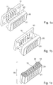
- Figure 1a shows a light source receptacle 10 on which a plurality of light source positions 11 are provided, each of which is designed to accommodate a light source 15.
- the light source receptacle 10 is designed, for example, as a printed circuit board and has an electrical wiring structure (not shown) which is required for operating the light sources 15 and which allows each individual light source to be controlled selectively.
- the light source positions 11 are formed by depressions in the light source receptacle, in each of which a light source 15 can be attached.
- the light source receptacle 10 and the microlens array are matched to one another such that precisely one of the microlenses 21 is assigned to each of the light source positions 11.
- the microlenses 21 are arranged within the microlens array in the same two-dimensional grid as the light source positions are arranged on the light source receptacle 10.
- the microlens array 20 is designed as a one-piece body and is formed, for example, by a glass body or a transparent plastic body.
- the diameter of the individual microlenses is, for example, in the ⁇ m range or in the mm range.
- some or all of the light source positions 11 are each provided with a light source 15, cf. Figure 1b .
- LEDs and / or OLEDs and / or VCSELs are used as light sources 15.
- the light sources 15 have a large number of different emission spectra.
- each of the light sources 15 has a different emission spectrum than the other light sources 15.
- several identical light sources 15 can be used, for example in order to obtain sufficient illumination intensity even in a spectral range with weak light sources.
- the body of the microlens array 20 is equipped with fastening pins 22 which are inserted into matching holes 12 in the light source receptacle 10.
- the microlens array 20 and the light source receptacle 10 are fixed to one another, for example by means of a form-fit connection or by gluing.
- the light source receptacle 11 with the light sources 15 arranged thereon and the microlens array 20 fastened on the light source receptacle 11 form an illumination device 50, cf. Figure 1c .
- the light emitted by the individual light sources 15 is collected by the microlens 21 arranged in front of the respective light source 15.
- the light source receptacle 10 is designed so that the light source positions 11 relative to the positions of the holes 12 of the Light source receptacle 10 are subject to the smallest possible tolerances. Since the fastening pins 22 are designed as integral components of the body of the microlens array 20, their position relative to the microlenses 21 is very precisely defined. In this way, by fastening the microlens array 20 by means of the fastening pins 22, the optimal position of the microlens array 20 relative to the light sources 15 is automatically achieved. During the production of the sensor 100, therefore, no adjustment of the lighting device 50 is required.
- the sensor for checking documents of value is explained below using the example of a reflectance sensor.
- the sensor according to the invention can, however, also be designed as a transmission sensor.
- the detection device will be arranged opposite to the illumination device, so that the illumination light transmitted through the value document is detected.
- the lighting device 50 is installed in a sensor 100 which is designed to check documents of value, cf. Figure 2a .
- the light emitted by the lighting device 50 is imaged onto the value document 1 through an imaging lens 25.
- the value document 1 is illuminated over a certain area with homogeneous light intensity.
- other optical components can also be used as imaging optics as an alternative to the imaging lens 25, for example lens systems, diffractive optical components, for example a Fresnel lens, or imaging mirrors.
- portions of the illuminating light are remitted from the document of value 1.
- the light remitted by the document of value 1 is detected with the aid of a detection device 30 which has a light-sensitive area 31 has.
- the detection device 30 can be formed, for example, by a photodiode or a phototransistor.
- detection optics 35 can be arranged in front of the detection device 30, by means of which the light reflected from the value document 1 is collected and directed onto the light-sensitive area 31.
- the illuminating light is imaged perpendicularly onto the document of value 1 and the detection device 30 detects the light remitted at an oblique angle.
- the illumination can also take place at an oblique angle and the detection device can detect the light reflected in the vertical direction or the light reflected in the oblique direction.
- the sensor 100 has a housing 90, on the underside of which a transparent window 101 is arranged.
- the light emitted by the lighting device 50 is imaged through the window 101 onto a document of value 1 to be checked, which is transported past the sensor 100 along a transport direction T.
- the lighting device 50, in particular the light sources 15, and the detection device 30 are controlled by a control device 60 which, in this example, is arranged within the housing 90.
- the control device 60 switches the light sources 15 on and off again one after the other, for example in such a way that exactly one light source 15 is switched on at each point in time.
- the detection device 30 in each case records a measured value which corresponds to the light intensity remitted by the value document 1.
- the value document 1 is illuminated one after the other with the different emission spectra of the different light sources 15. Since the detection device 30 records a measured value synchronously with the illumination by the light sources 15, the light intensity remitted by the value document 1 is measured in each spectral range that the light sources 15 specify.
- the control device 60 controls the light sources 15 so that the lighting sequence with which the light sources 15 are switched on and off is repeated periodically.
- the control device 60 can be programmed in such a way that each light source 15 of the lighting device 50 is switched on and off exactly once during each lighting sequence.
- a light source 15 can also be activated several times per lighting sequence, e.g. to compensate for the low intensity of a low-intensity light source 15 by multiple measurements.
- a lighting sequence can either contain the control of all the light sources 15 present in the lighting device 50 or only a subset of the light sources 15 present. After a lighting sequence, i.
- the duration of the The lighting sequence is matched to the transport speed of the document of value 1 in such a way that the various measured values of an illumination sequence originate at least approximately from the same detection area on the document of value 1.
- the distance covered by the document of value 1 from the beginning to the end of the same lighting sequence is therefore much shorter than the length of the detection area.
- the measured values obtained during a lighting sequence can e.g. provide a spectral dependence of the remission of the respective detection area.
- the sensor 100 is produced from a sensor platform 70, which consists of the following elements, cf. Figure 2b : the light source receptacle 10, the microlens array 20, the imaging optics 25 and the detection device 30.
- the control device 60 and / or the housing 90 and / or the detection optics 35 belong to the sensor platform 70.
- the sensor according to the invention can also be implemented without these elements.
- various sensors can be produced from the sensor platform 70.
- either a sensor of the first type 100A or a sensor of the second type 100B can be produced from the same sensor platform 70, for example.
- the sensors of the first type 100A and the sensors of the second type 100B are equipped with the same selection S of light sources 15, cf. Figure 3a .
- the selection S of light sources 15 with which the sensor platform 70 is equipped in the manufacture of the sensors 100A and 100B consists in the example shown of 14 different light sources 15.
- the spectral position of the various emission maxima of these light sources 15 is shown in FIG Figure 3a denoted by ⁇ 1 to ⁇ 14.
- the emission spectra of the light sources 15 extend, for example, from the ultraviolet through the visible to the near-infrared spectral range. From the selection S, however, the sensors of the first type 100A and the sensors of the second type 100B use different subsets of light sources 15.
- the sensor of the first type 100A uses the subset A, which consists of the light sources with the wavelengths ⁇ 1- ⁇ 3, ⁇ 5, ⁇ 7 and ⁇ 9- ⁇ 14 exists, cf. Figure 3b .
- the sensor of the second type 100B uses the subset B, which consists of the light sources with the wavelengths ⁇ 4- ⁇ 10, cf. Figure 3c .
- the control device 60 of the sensor 100A is configured such that the light sources of the wavelengths ⁇ 1- ⁇ 3, ⁇ 5, ⁇ 7 and ⁇ 9- ⁇ 14 are switched on and off one after the other during an illumination sequence.
- the control device 60 of the sensor of the second type 100B is configured in such a way that, during a lighting sequence of the sensor of the second type 100B the light sources of the wavelengths ⁇ 4- ⁇ 10 are switched on and off successively.
- the sensors of the second type have a different selection of light sources than the sensors of the first type 100A.
- the sensor platform 70 is therefore equipped with a different selection of light sources 15 than for producing the sensors 100A.
- the sensors of the first type 100A are equipped with a first selection S A of light sources 15A and the sensors of the second type 100B with a second selection S B of light sources 15B, cf. Figures 4a-b .
- the first selection S A consists of 10 different light sources 15A, the wavelengths of which are denoted by ⁇ 1- ⁇ 10.
- the second selection S B consists of 11 different light sources 15B, the wavelengths of which are denoted by ⁇ 10- ⁇ 20.
- the light sources 15B can be partially identical to the light sources 15A.
Landscapes
- Health & Medical Sciences (AREA)
- General Health & Medical Sciences (AREA)
- Physics & Mathematics (AREA)
- Toxicology (AREA)
- General Physics & Mathematics (AREA)
- Life Sciences & Earth Sciences (AREA)
- Engineering & Computer Science (AREA)
- Spectroscopy & Molecular Physics (AREA)
- Biophysics (AREA)
- Molecular Biology (AREA)
- Veterinary Medicine (AREA)
- Public Health (AREA)
- Animal Behavior & Ethology (AREA)
- Pathology (AREA)
- Biomedical Technology (AREA)
- Heart & Thoracic Surgery (AREA)
- Medical Informatics (AREA)
- Surgery (AREA)
- Theoretical Computer Science (AREA)
- Optics & Photonics (AREA)
- Human Computer Interaction (AREA)
- Multimedia (AREA)
- Facsimile Scanning Arrangements (AREA)
- Inspection Of Paper Currency And Valuable Securities (AREA)
- Facsimile Heads (AREA)
- Investigating Or Analysing Materials By Optical Means (AREA)
Applications Claiming Priority (2)
| Application Number | Priority Date | Filing Date | Title |
|---|---|---|---|
| DE102009058804A DE102009058804A1 (de) | 2009-12-18 | 2009-12-18 | Sensor zur Prüfung von Wertdokumenten |
| PCT/EP2010/007703 WO2011072862A1 (de) | 2009-12-18 | 2010-12-16 | Sensor zur prüfung von wertdokumenten |
Publications (2)
| Publication Number | Publication Date |
|---|---|
| EP2513873A1 EP2513873A1 (de) | 2012-10-24 |
| EP2513873B1 true EP2513873B1 (de) | 2020-10-07 |
Family
ID=43709179
Family Applications (1)
| Application Number | Title | Priority Date | Filing Date |
|---|---|---|---|
| EP10792845.9A Active EP2513873B1 (de) | 2009-12-18 | 2010-12-16 | Sensor zur prüfung von wertdokumenten |
Country Status (7)
Families Citing this family (14)
| Publication number | Priority date | Publication date | Assignee | Title |
|---|---|---|---|---|
| CN102913810A (zh) * | 2011-08-01 | 2013-02-06 | 吉鸿电子股份有限公司 | 辨识装置及其光源模块 |
| ES2653673T3 (es) * | 2011-09-12 | 2018-02-08 | International Currency Technologies Corporation | Dispositivo de validación y módulo fuente de luz del mismo |
| JP6502630B2 (ja) | 2013-09-30 | 2019-04-17 | 株式会社リコー | 光学センサ、光学検査装置、及び光学特性検出方法 |
| DE102014105746C5 (de) * | 2013-12-05 | 2020-12-24 | Sick Ag | Optoelektronischer Sensor und Verfahren zur Erfassung glänzender Objekte |
| CN103791452B (zh) * | 2014-02-21 | 2017-01-04 | 中国人民银行印制科学技术研究所 | 光源系统 |
| US9273846B1 (en) * | 2015-01-29 | 2016-03-01 | Heptagon Micro Optics Pte. Ltd. | Apparatus for producing patterned illumination including at least one array of light sources and at least one array of microlenses |
| US10509147B2 (en) | 2015-01-29 | 2019-12-17 | ams Sensors Singapore Pte. Ltd | Apparatus for producing patterned illumination using arrays of light sources and lenses |
| US11728356B2 (en) * | 2015-05-14 | 2023-08-15 | Semiconductor Energy Laboratory Co., Ltd. | Photoelectric conversion element and imaging device |
| EP3408585B1 (en) * | 2016-01-26 | 2020-12-09 | Heptagon Micro Optics Pte. Ltd. | Multi-mode illumination module and related method |
| CN109414163B (zh) | 2016-07-01 | 2023-01-24 | 赛莱特私人有限公司 | 用于分析样本的装置及方法 |
| EP3503049B1 (de) * | 2017-12-22 | 2021-02-24 | CI Tech Sensors AG | Vorrichtung und verfahren zum nachweis eines maschinenlesbaren sicherheitsmerkmals eines wertdokuments |
| US11085609B1 (en) * | 2021-02-08 | 2021-08-10 | Himax Technologies Limited | Illumination device |
| TW202432344A (zh) * | 2022-10-24 | 2024-08-16 | 日商Towa股份有限公司 | 光學零件的製造方法 |
| JP2024062350A (ja) * | 2022-10-24 | 2024-05-09 | Towa株式会社 | 光学部品の製造方法 |
Citations (2)
| Publication number | Priority date | Publication date | Assignee | Title |
|---|---|---|---|---|
| DE102005029119A1 (de) * | 2005-06-23 | 2006-12-28 | Carl Zeiss Jena Gmbh | Beleuchtungsvorrichtung, insbesondere für Mikroskope |
| DE202007013090U1 (de) * | 2007-09-19 | 2007-12-13 | International Currency Technologies Corporation | Anti-EMI-Linsenmodul |
Family Cites Families (16)
| Publication number | Priority date | Publication date | Assignee | Title |
|---|---|---|---|---|
| US3743422A (en) * | 1970-06-18 | 1973-07-03 | Westinghouse Electric Corp | Optical image processor |
| US3765749A (en) * | 1972-05-23 | 1973-10-16 | Bell Telephone Labor Inc | Optical memory storage and retrieval system |
| WO1985002928A1 (en) | 1983-12-27 | 1985-07-04 | Bergstroem Arne | Apparatus for authenticating bank notes |
| US5875259A (en) * | 1990-02-05 | 1999-02-23 | Cummins-Allison Corp. | Method and apparatus for discriminating and counting documents |
| CA2169865C (en) | 1996-02-20 | 2007-07-03 | Vitold A. Khvostov | Optical reflection sensing arrangement for scanning devices |
| US5923413A (en) * | 1996-11-15 | 1999-07-13 | Interbold | Universal bank note denominator and validator |
| DE10027726A1 (de) * | 2000-06-03 | 2001-12-06 | Bundesdruckerei Gmbh | Sensor für die Echtheitserkennung von Signets auf Dokumenten |
| GB2366371A (en) * | 2000-09-04 | 2002-03-06 | Mars Inc | Sensing documents such as currency items |
| US7221512B2 (en) * | 2002-01-24 | 2007-05-22 | Nanoventions, Inc. | Light control material for displaying color information, and images |
| JP2005276849A (ja) | 2004-02-24 | 2005-10-06 | Ricoh Co Ltd | Ledアレイ素子、光書込み装置、光学読取装置及びledアレイ素子のマイクロレンズアレイの製造方法 |
| DE102004021397A1 (de) * | 2004-04-30 | 2005-11-24 | Bundesdruckerei Gmbh | Vorrichtung und Verfahren zur Echtheitsüberprüfung eines mit einem Sicherheitsmerkmal versehenen Sicherheits- oder Wertdokuments, das auf einem Träger aufgebracht ist |
| JP2006058488A (ja) * | 2004-08-18 | 2006-03-02 | Nippon Sheet Glass Co Ltd | 照明光学装置およびこれを用いた投影型表示装置 |
| US7715001B2 (en) * | 2006-02-13 | 2010-05-11 | Pacific Biosciences Of California, Inc. | Methods and systems for simultaneous real-time monitoring of optical signals from multiple sources |
| ES2390016T3 (es) * | 2006-08-22 | 2012-11-05 | Mei, Inc. | Disposición de detector óptico para aceptor de documentos |
| US7489456B2 (en) * | 2007-05-02 | 2009-02-10 | International Currency Technologies Corporation | Lens module |
| DE102007031230B3 (de) * | 2007-07-04 | 2008-10-30 | Bundesdruckerei Gmbh | Dokumentenerfassungssystem und Dokumentenerfassungsverfahren |
-
2009
- 2009-12-18 DE DE102009058804A patent/DE102009058804A1/de not_active Withdrawn
-
2010
- 2010-12-16 JP JP2012543526A patent/JP5615935B2/ja active Active
- 2010-12-16 ES ES10792845T patent/ES2827182T3/es active Active
- 2010-12-16 US US13/515,720 patent/US8749768B2/en active Active
- 2010-12-16 WO PCT/EP2010/007703 patent/WO2011072862A1/de active Application Filing
- 2010-12-16 EP EP10792845.9A patent/EP2513873B1/de active Active
- 2010-12-16 KR KR1020127018659A patent/KR101841301B1/ko active Active
Patent Citations (2)
| Publication number | Priority date | Publication date | Assignee | Title |
|---|---|---|---|---|
| DE102005029119A1 (de) * | 2005-06-23 | 2006-12-28 | Carl Zeiss Jena Gmbh | Beleuchtungsvorrichtung, insbesondere für Mikroskope |
| DE202007013090U1 (de) * | 2007-09-19 | 2007-12-13 | International Currency Technologies Corporation | Anti-EMI-Linsenmodul |
Also Published As
| Publication number | Publication date |
|---|---|
| ES2827182T3 (es) | 2021-05-20 |
| JP2013514566A (ja) | 2013-04-25 |
| KR101841301B1 (ko) | 2018-03-22 |
| US20120257191A1 (en) | 2012-10-11 |
| US8749768B2 (en) | 2014-06-10 |
| KR20120105525A (ko) | 2012-09-25 |
| EP2513873A1 (de) | 2012-10-24 |
| WO2011072862A1 (de) | 2011-06-23 |
| JP5615935B2 (ja) | 2014-10-29 |
| DE102009058804A1 (de) | 2011-06-22 |
Similar Documents
| Publication | Publication Date | Title |
|---|---|---|
| EP2513873B1 (de) | Sensor zur prüfung von wertdokumenten | |
| EP2513875B1 (de) | Spektralsensor zur prüfung von wertdokumenten | |
| EP1396182B1 (de) | Optische sensorvorrichtung | |
| EP2620894B1 (de) | Optoelektronischer Sensor und Verfahren zur Erfassung von Objektinformationen | |
| DE102018114186A1 (de) | Optischer Fingerabdrucksensor und Verfahren zum Herstellen eines entsprechenden Erfassungsmoduls dafür | |
| EP0338123A2 (de) | Einrichtung zum Erkennnen von Dokumenten | |
| EP2513874B1 (de) | Sensor zur prüfung von wertdokumenten | |
| WO2008017490A2 (de) | Optisches filter und verfahren zur herstellung desselben, sowie vorrichtung zur untersuchung elektromagnetischer strahlung | |
| WO2006045621A1 (de) | Messeinrichtung und abtastvorrichtung zur bildelementweisen fotoelektrischen ausmessung eines messobjekts | |
| DE19924750A1 (de) | Leseanordnung für Informationsstreifen mit optisch kodierter Information | |
| DE19532877A1 (de) | Vorrichtung zur linienförmigen Beleuchtung von Blattgut, wie z. B. Banknoten oder Wertpapiere | |
| EP2773928B1 (de) | Sensor zur prüfung von wertdokumenten | |
| EP0802499A2 (de) | Lumineszenztaster | |
| EP1265198A2 (de) | Vorrichtung und Verfahren zur Untersuchung von Dokumenten | |
| EP3480571B1 (de) | Vorrichtung zum optischen erkennen von objekten | |
| EP3267367A1 (de) | Zählscheibenvorrichtung | |
| WO2015135676A1 (de) | Bildaufnahmevorrichtung, insbesondere zur fahrzeugvermessung | |
| DE102008007731B4 (de) | Verfahren und Vorrichtung zur Identifizierung und Authentifizierung von Objekten | |
| DE102006039073A1 (de) | Vorrichtung zur Untersuchung der spektralen und örtlichen Verteilung einer elektromagnetischen, von einem Gegenstand ausgehenden Strahlung | |
| EP1456602B1 (de) | Sensor zur visuellen positionserfassung ( bauelement, substrat ) mit einer modularen beleuchtungseinheit | |
| EP2531982A2 (de) | Beleuchtungseinrichtung und sensor zur prüfung von wertdokumenten | |
| WO2005109352A1 (de) | Vorrichtung und verfahren zur echtheitsüberprüfung eines mit einem sicherheitsmerkmal versehenen sicherheits- oder wertdokuments, das auf einem träger aufgebracht ist | |
| WO2005092568A1 (de) | Vorrichtung und verfahren zum erfassen des vorliegens oder fehlens eines bauteils | |
| DE19709310C2 (de) | Optoelektronische Justierhilfe | |
| EP3220112B1 (de) | Vorrichtung mit wenigstens einem optischen sensormodul und betriebsverfahren hierfür |
Legal Events
| Date | Code | Title | Description |
|---|---|---|---|
| PUAI | Public reference made under article 153(3) epc to a published international application that has entered the european phase |
Free format text: ORIGINAL CODE: 0009012 |
|
| 17P | Request for examination filed |
Effective date: 20120718 |
|
| AK | Designated contracting states |
Kind code of ref document: A1 Designated state(s): AL AT BE BG CH CY CZ DE DK EE ES FI FR GB GR HR HU IE IS IT LI LT LU LV MC MK MT NL NO PL PT RO RS SE SI SK SM TR |
|
| DAX | Request for extension of the european patent (deleted) | ||
| 17Q | First examination report despatched |
Effective date: 20151214 |
|
| RAP1 | Party data changed (applicant data changed or rights of an application transferred) |
Owner name: GIESECKE+DEVRIENT CURRENCY TECHNOLOGY GMBH |
|
| STAA | Information on the status of an ep patent application or granted ep patent |
Free format text: STATUS: EXAMINATION IS IN PROGRESS |
|
| REG | Reference to a national code |
Ref country code: DE Ref legal event code: R079 Ref document number: 502010016770 Country of ref document: DE Free format text: PREVIOUS MAIN CLASS: G07D0007120000 Ipc: G07D0007121000 |
|
| RIC1 | Information provided on ipc code assigned before grant |
Ipc: G07D 7/121 20160101AFI20200331BHEP Ipc: G07D 7/1205 20160101ALI20200331BHEP |
|
| GRAP | Despatch of communication of intention to grant a patent |
Free format text: ORIGINAL CODE: EPIDOSNIGR1 |
|
| STAA | Information on the status of an ep patent application or granted ep patent |
Free format text: STATUS: GRANT OF PATENT IS INTENDED |
|
| INTG | Intention to grant announced |
Effective date: 20200526 |
|
| GRAS | Grant fee paid |
Free format text: ORIGINAL CODE: EPIDOSNIGR3 |
|
| GRAA | (expected) grant |
Free format text: ORIGINAL CODE: 0009210 |
|
| STAA | Information on the status of an ep patent application or granted ep patent |
Free format text: STATUS: THE PATENT HAS BEEN GRANTED |
|
| AK | Designated contracting states |
Kind code of ref document: B1 Designated state(s): AL AT BE BG CH CY CZ DE DK EE ES FI FR GB GR HR HU IE IS IT LI LT LU LV MC MK MT NL NO PL PT RO RS SE SI SK SM TR |
|
| REG | Reference to a national code |
Ref country code: GB Ref legal event code: FG4D Free format text: NOT ENGLISH |
|
| REG | Reference to a national code |
Ref country code: AT Ref legal event code: REF Ref document number: 1321978 Country of ref document: AT Kind code of ref document: T Effective date: 20201015 Ref country code: CH Ref legal event code: EP |
|
| REG | Reference to a national code |
Ref country code: IE Ref legal event code: FG4D Free format text: LANGUAGE OF EP DOCUMENT: GERMAN |
|
| REG | Reference to a national code |
Ref country code: DE Ref legal event code: R096 Ref document number: 502010016770 Country of ref document: DE |
|
| REG | Reference to a national code |
Ref country code: CH Ref legal event code: NV Representative=s name: PATENTANWAELTE SCHAAD, BALASS, MENZL AND PARTN, CH |
|
| REG | Reference to a national code |
Ref country code: NL Ref legal event code: MP Effective date: 20201007 |
|
| PG25 | Lapsed in a contracting state [announced via postgrant information from national office to epo] |
Ref country code: FI Free format text: LAPSE BECAUSE OF FAILURE TO SUBMIT A TRANSLATION OF THE DESCRIPTION OR TO PAY THE FEE WITHIN THE PRESCRIBED TIME-LIMIT Effective date: 20201007 Ref country code: RS Free format text: LAPSE BECAUSE OF FAILURE TO SUBMIT A TRANSLATION OF THE DESCRIPTION OR TO PAY THE FEE WITHIN THE PRESCRIBED TIME-LIMIT Effective date: 20201007 Ref country code: NL Free format text: LAPSE BECAUSE OF FAILURE TO SUBMIT A TRANSLATION OF THE DESCRIPTION OR TO PAY THE FEE WITHIN THE PRESCRIBED TIME-LIMIT Effective date: 20201007 Ref country code: PT Free format text: LAPSE BECAUSE OF FAILURE TO SUBMIT A TRANSLATION OF THE DESCRIPTION OR TO PAY THE FEE WITHIN THE PRESCRIBED TIME-LIMIT Effective date: 20210208 Ref country code: NO Free format text: LAPSE BECAUSE OF FAILURE TO SUBMIT A TRANSLATION OF THE DESCRIPTION OR TO PAY THE FEE WITHIN THE PRESCRIBED TIME-LIMIT Effective date: 20210107 Ref country code: GR Free format text: LAPSE BECAUSE OF FAILURE TO SUBMIT A TRANSLATION OF THE DESCRIPTION OR TO PAY THE FEE WITHIN THE PRESCRIBED TIME-LIMIT Effective date: 20210108 |
|
| REG | Reference to a national code |
Ref country code: LT Ref legal event code: MG4D |
|
| REG | Reference to a national code |
Ref country code: ES Ref legal event code: FG2A Ref document number: 2827182 Country of ref document: ES Kind code of ref document: T3 Effective date: 20210520 |
|
| PG25 | Lapsed in a contracting state [announced via postgrant information from national office to epo] |
Ref country code: SE Free format text: LAPSE BECAUSE OF FAILURE TO SUBMIT A TRANSLATION OF THE DESCRIPTION OR TO PAY THE FEE WITHIN THE PRESCRIBED TIME-LIMIT Effective date: 20201007 Ref country code: LV Free format text: LAPSE BECAUSE OF FAILURE TO SUBMIT A TRANSLATION OF THE DESCRIPTION OR TO PAY THE FEE WITHIN THE PRESCRIBED TIME-LIMIT Effective date: 20201007 Ref country code: PL Free format text: LAPSE BECAUSE OF FAILURE TO SUBMIT A TRANSLATION OF THE DESCRIPTION OR TO PAY THE FEE WITHIN THE PRESCRIBED TIME-LIMIT Effective date: 20201007 Ref country code: BG Free format text: LAPSE BECAUSE OF FAILURE TO SUBMIT A TRANSLATION OF THE DESCRIPTION OR TO PAY THE FEE WITHIN THE PRESCRIBED TIME-LIMIT Effective date: 20210107 Ref country code: IS Free format text: LAPSE BECAUSE OF FAILURE TO SUBMIT A TRANSLATION OF THE DESCRIPTION OR TO PAY THE FEE WITHIN THE PRESCRIBED TIME-LIMIT Effective date: 20210207 |
|
| PG25 | Lapsed in a contracting state [announced via postgrant information from national office to epo] |
Ref country code: HR Free format text: LAPSE BECAUSE OF FAILURE TO SUBMIT A TRANSLATION OF THE DESCRIPTION OR TO PAY THE FEE WITHIN THE PRESCRIBED TIME-LIMIT Effective date: 20201007 |
|
| REG | Reference to a national code |
Ref country code: DE Ref legal event code: R097 Ref document number: 502010016770 Country of ref document: DE |
|
| PG25 | Lapsed in a contracting state [announced via postgrant information from national office to epo] |
Ref country code: LT Free format text: LAPSE BECAUSE OF FAILURE TO SUBMIT A TRANSLATION OF THE DESCRIPTION OR TO PAY THE FEE WITHIN THE PRESCRIBED TIME-LIMIT Effective date: 20201007 Ref country code: RO Free format text: LAPSE BECAUSE OF FAILURE TO SUBMIT A TRANSLATION OF THE DESCRIPTION OR TO PAY THE FEE WITHIN THE PRESCRIBED TIME-LIMIT Effective date: 20201007 Ref country code: SK Free format text: LAPSE BECAUSE OF FAILURE TO SUBMIT A TRANSLATION OF THE DESCRIPTION OR TO PAY THE FEE WITHIN THE PRESCRIBED TIME-LIMIT Effective date: 20201007 Ref country code: SM Free format text: LAPSE BECAUSE OF FAILURE TO SUBMIT A TRANSLATION OF THE DESCRIPTION OR TO PAY THE FEE WITHIN THE PRESCRIBED TIME-LIMIT Effective date: 20201007 Ref country code: EE Free format text: LAPSE BECAUSE OF FAILURE TO SUBMIT A TRANSLATION OF THE DESCRIPTION OR TO PAY THE FEE WITHIN THE PRESCRIBED TIME-LIMIT Effective date: 20201007 Ref country code: CZ Free format text: LAPSE BECAUSE OF FAILURE TO SUBMIT A TRANSLATION OF THE DESCRIPTION OR TO PAY THE FEE WITHIN THE PRESCRIBED TIME-LIMIT Effective date: 20201007 |
|
| PLBE | No opposition filed within time limit |
Free format text: ORIGINAL CODE: 0009261 |
|
| STAA | Information on the status of an ep patent application or granted ep patent |
Free format text: STATUS: NO OPPOSITION FILED WITHIN TIME LIMIT |
|
| PG25 | Lapsed in a contracting state [announced via postgrant information from national office to epo] |
Ref country code: DK Free format text: LAPSE BECAUSE OF FAILURE TO SUBMIT A TRANSLATION OF THE DESCRIPTION OR TO PAY THE FEE WITHIN THE PRESCRIBED TIME-LIMIT Effective date: 20201007 Ref country code: MC Free format text: LAPSE BECAUSE OF FAILURE TO SUBMIT A TRANSLATION OF THE DESCRIPTION OR TO PAY THE FEE WITHIN THE PRESCRIBED TIME-LIMIT Effective date: 20201007 |
|
| REG | Reference to a national code |
Ref country code: BE Ref legal event code: MM Effective date: 20201231 |
|
| 26N | No opposition filed |
Effective date: 20210708 |
|
| PG25 | Lapsed in a contracting state [announced via postgrant information from national office to epo] |
Ref country code: AL Free format text: LAPSE BECAUSE OF FAILURE TO SUBMIT A TRANSLATION OF THE DESCRIPTION OR TO PAY THE FEE WITHIN THE PRESCRIBED TIME-LIMIT Effective date: 20201007 Ref country code: IE Free format text: LAPSE BECAUSE OF NON-PAYMENT OF DUE FEES Effective date: 20201216 Ref country code: IT Free format text: LAPSE BECAUSE OF FAILURE TO SUBMIT A TRANSLATION OF THE DESCRIPTION OR TO PAY THE FEE WITHIN THE PRESCRIBED TIME-LIMIT Effective date: 20201007 Ref country code: LU Free format text: LAPSE BECAUSE OF NON-PAYMENT OF DUE FEES Effective date: 20201216 |
|
| PG25 | Lapsed in a contracting state [announced via postgrant information from national office to epo] |
Ref country code: SI Free format text: LAPSE BECAUSE OF FAILURE TO SUBMIT A TRANSLATION OF THE DESCRIPTION OR TO PAY THE FEE WITHIN THE PRESCRIBED TIME-LIMIT Effective date: 20201007 |
|
| PG25 | Lapsed in a contracting state [announced via postgrant information from national office to epo] |
Ref country code: IS Free format text: LAPSE BECAUSE OF FAILURE TO SUBMIT A TRANSLATION OF THE DESCRIPTION OR TO PAY THE FEE WITHIN THE PRESCRIBED TIME-LIMIT Effective date: 20210207 Ref country code: TR Free format text: LAPSE BECAUSE OF FAILURE TO SUBMIT A TRANSLATION OF THE DESCRIPTION OR TO PAY THE FEE WITHIN THE PRESCRIBED TIME-LIMIT Effective date: 20201007 Ref country code: MT Free format text: LAPSE BECAUSE OF FAILURE TO SUBMIT A TRANSLATION OF THE DESCRIPTION OR TO PAY THE FEE WITHIN THE PRESCRIBED TIME-LIMIT Effective date: 20201007 Ref country code: CY Free format text: LAPSE BECAUSE OF FAILURE TO SUBMIT A TRANSLATION OF THE DESCRIPTION OR TO PAY THE FEE WITHIN THE PRESCRIBED TIME-LIMIT Effective date: 20201007 |
|
| PG25 | Lapsed in a contracting state [announced via postgrant information from national office to epo] |
Ref country code: MK Free format text: LAPSE BECAUSE OF FAILURE TO SUBMIT A TRANSLATION OF THE DESCRIPTION OR TO PAY THE FEE WITHIN THE PRESCRIBED TIME-LIMIT Effective date: 20201007 |
|
| PG25 | Lapsed in a contracting state [announced via postgrant information from national office to epo] |
Ref country code: BE Free format text: LAPSE BECAUSE OF NON-PAYMENT OF DUE FEES Effective date: 20201231 |
|
| P01 | Opt-out of the competence of the unified patent court (upc) registered |
Effective date: 20230520 |
|
| PGFP | Annual fee paid to national office [announced via postgrant information from national office to epo] |
Ref country code: DE Payment date: 20241216 Year of fee payment: 15 |
|
| PGFP | Annual fee paid to national office [announced via postgrant information from national office to epo] |
Ref country code: GB Payment date: 20241218 Year of fee payment: 15 |
|
| PGFP | Annual fee paid to national office [announced via postgrant information from national office to epo] |
Ref country code: FR Payment date: 20241219 Year of fee payment: 15 |
|
| PGFP | Annual fee paid to national office [announced via postgrant information from national office to epo] |
Ref country code: AT Payment date: 20241213 Year of fee payment: 15 |
|
| PGFP | Annual fee paid to national office [announced via postgrant information from national office to epo] |
Ref country code: ES Payment date: 20250117 Year of fee payment: 15 |
|
| PGFP | Annual fee paid to national office [announced via postgrant information from national office to epo] |
Ref country code: CH Payment date: 20250101 Year of fee payment: 15 |