EP2513615B1 - Radarfüllstandsmesssystem und zugehöriges verfahren - Google Patents
Radarfüllstandsmesssystem und zugehöriges verfahren Download PDFInfo
- Publication number
- EP2513615B1 EP2513615B1 EP10837979.3A EP10837979A EP2513615B1 EP 2513615 B1 EP2513615 B1 EP 2513615B1 EP 10837979 A EP10837979 A EP 10837979A EP 2513615 B1 EP2513615 B1 EP 2513615B1
- Authority
- EP
- European Patent Office
- Prior art keywords
- signal
- pulse
- level gauge
- radar level
- gauge system
- Prior art date
- Legal status (The legal status is an assumption and is not a legal conclusion. Google has not performed a legal analysis and makes no representation as to the accuracy of the status listed.)
- Active
Links
Images


Classifications
-
- G—PHYSICS
- G01—MEASURING; TESTING
- G01S—RADIO DIRECTION-FINDING; RADIO NAVIGATION; DETERMINING DISTANCE OR VELOCITY BY USE OF RADIO WAVES; LOCATING OR PRESENCE-DETECTING BY USE OF THE REFLECTION OR RERADIATION OF RADIO WAVES; ANALOGOUS ARRANGEMENTS USING OTHER WAVES
- G01S13/00—Systems using the reflection or reradiation of radio waves, e.g. radar systems; Analogous systems using reflection or reradiation of waves whose nature or wavelength is irrelevant or unspecified
- G01S13/02—Systems using reflection of radio waves, e.g. primary radar systems; Analogous systems
- G01S13/06—Systems determining position data of a target
- G01S13/08—Systems for measuring distance only
- G01S13/32—Systems for measuring distance only using transmission of continuous waves, whether amplitude-, frequency-, or phase-modulated, or unmodulated
-
- G—PHYSICS
- G01—MEASURING; TESTING
- G01F—MEASURING VOLUME, VOLUME FLOW, MASS FLOW OR LIQUID LEVEL; METERING BY VOLUME
- G01F23/00—Indicating or measuring liquid level or level of fluent solid material, e.g. indicating in terms of volume or indicating by means of an alarm
- G01F23/22—Indicating or measuring liquid level or level of fluent solid material, e.g. indicating in terms of volume or indicating by means of an alarm by measuring physical variables, other than linear dimensions, pressure or weight, dependent on the level to be measured, e.g. by difference of heat transfer of steam or water
- G01F23/28—Indicating or measuring liquid level or level of fluent solid material, e.g. indicating in terms of volume or indicating by means of an alarm by measuring physical variables, other than linear dimensions, pressure or weight, dependent on the level to be measured, e.g. by difference of heat transfer of steam or water by measuring the variations of parameters of electromagnetic or acoustic waves applied directly to the liquid or fluent solid material
- G01F23/284—Electromagnetic waves
-
- G—PHYSICS
- G01—MEASURING; TESTING
- G01F—MEASURING VOLUME, VOLUME FLOW, MASS FLOW OR LIQUID LEVEL; METERING BY VOLUME
- G01F23/00—Indicating or measuring liquid level or level of fluent solid material, e.g. indicating in terms of volume or indicating by means of an alarm
- G01F23/80—Arrangements for signal processing
- G01F23/802—Particular electronic circuits for digital processing equipment
-
- G—PHYSICS
- G01—MEASURING; TESTING
- G01S—RADIO DIRECTION-FINDING; RADIO NAVIGATION; DETERMINING DISTANCE OR VELOCITY BY USE OF RADIO WAVES; LOCATING OR PRESENCE-DETECTING BY USE OF THE REFLECTION OR RERADIATION OF RADIO WAVES; ANALOGOUS ARRANGEMENTS USING OTHER WAVES
- G01S13/00—Systems using the reflection or reradiation of radio waves, e.g. radar systems; Analogous systems using reflection or reradiation of waves whose nature or wavelength is irrelevant or unspecified
- G01S13/02—Systems using reflection of radio waves, e.g. primary radar systems; Analogous systems
- G01S13/06—Systems determining position data of a target
- G01S13/08—Systems for measuring distance only
- G01S13/10—Systems for measuring distance only using transmission of interrupted, pulse modulated waves
- G01S13/103—Systems for measuring distance only using transmission of interrupted, pulse modulated waves particularities of the measurement of the distance
-
- G—PHYSICS
- G01—MEASURING; TESTING
- G01S—RADIO DIRECTION-FINDING; RADIO NAVIGATION; DETERMINING DISTANCE OR VELOCITY BY USE OF RADIO WAVES; LOCATING OR PRESENCE-DETECTING BY USE OF THE REFLECTION OR RERADIATION OF RADIO WAVES; ANALOGOUS ARRANGEMENTS USING OTHER WAVES
- G01S13/00—Systems using the reflection or reradiation of radio waves, e.g. radar systems; Analogous systems using reflection or reradiation of waves whose nature or wavelength is irrelevant or unspecified
- G01S13/88—Radar or analogous systems specially adapted for specific applications
-
- G—PHYSICS
- G01—MEASURING; TESTING
- G01S—RADIO DIRECTION-FINDING; RADIO NAVIGATION; DETERMINING DISTANCE OR VELOCITY BY USE OF RADIO WAVES; LOCATING OR PRESENCE-DETECTING BY USE OF THE REFLECTION OR RERADIATION OF RADIO WAVES; ANALOGOUS ARRANGEMENTS USING OTHER WAVES
- G01S7/00—Details of systems according to groups G01S13/00, G01S15/00, G01S17/00
- G01S7/02—Details of systems according to groups G01S13/00, G01S15/00, G01S17/00 of systems according to group G01S13/00
- G01S7/28—Details of pulse systems
- G01S7/285—Receivers
-
- G—PHYSICS
- G01—MEASURING; TESTING
- G01S—RADIO DIRECTION-FINDING; RADIO NAVIGATION; DETERMINING DISTANCE OR VELOCITY BY USE OF RADIO WAVES; LOCATING OR PRESENCE-DETECTING BY USE OF THE REFLECTION OR RERADIATION OF RADIO WAVES; ANALOGOUS ARRANGEMENTS USING OTHER WAVES
- G01S7/00—Details of systems according to groups G01S13/00, G01S15/00, G01S17/00
- G01S7/02—Details of systems according to groups G01S13/00, G01S15/00, G01S17/00 of systems according to group G01S13/00
- G01S7/35—Details of non-pulse systems
-
- G—PHYSICS
- G01—MEASURING; TESTING
- G01S—RADIO DIRECTION-FINDING; RADIO NAVIGATION; DETERMINING DISTANCE OR VELOCITY BY USE OF RADIO WAVES; LOCATING OR PRESENCE-DETECTING BY USE OF THE REFLECTION OR RERADIATION OF RADIO WAVES; ANALOGOUS ARRANGEMENTS USING OTHER WAVES
- G01S7/00—Details of systems according to groups G01S13/00, G01S15/00, G01S17/00
- G01S7/02—Details of systems according to groups G01S13/00, G01S15/00, G01S17/00 of systems according to group G01S13/00
- G01S7/40—Means for monitoring or calibrating
- G01S7/4004—Means for monitoring or calibrating of parts of a radar system
- G01S7/4021—Means for monitoring or calibrating of parts of a radar system of receivers
-
- G—PHYSICS
- G01—MEASURING; TESTING
- G01S—RADIO DIRECTION-FINDING; RADIO NAVIGATION; DETERMINING DISTANCE OR VELOCITY BY USE OF RADIO WAVES; LOCATING OR PRESENCE-DETECTING BY USE OF THE REFLECTION OR RERADIATION OF RADIO WAVES; ANALOGOUS ARRANGEMENTS USING OTHER WAVES
- G01S7/00—Details of systems according to groups G01S13/00, G01S15/00, G01S17/00
- G01S7/02—Details of systems according to groups G01S13/00, G01S15/00, G01S17/00 of systems according to group G01S13/00
- G01S7/40—Means for monitoring or calibrating
- G01S7/4052—Means for monitoring or calibrating by simulation of echoes
- G01S7/406—Means for monitoring or calibrating by simulation of echoes using internally generated reference signals, e.g. via delay line, via RF or IF signal injection or via integrated reference reflector or transponder
Definitions
- the present invention relates to a method of determining a filling level of a product contained in a tank using a pulsed radar level gauge system, and to a pulsed radar level gauge system.
- Radar level gauge (RLG) systems are in wide use for determining the filling level of a product contained in a tank. Radar level gauging is generally performed either by means of non-contact measurement, whereby electromagnetic signals are radiated towards the product contained in the tank, or by means of contact measurement, often referred to as guided wave radar (GWR), whereby electromagnetic signals are guided towards and into the product by a probe acting as a waveguide.
- GWR guided wave radar
- the probe is generally arranged to extend vertically from the top towards the bottom of the tank.
- the probe may also be arranged in a measurement tube, a so-called chamber, that is connected to the outer wall of the tank and is in fluid connection with the inside of the tank.
- the transmitted electromagnetic signals are reflected at the surface of the product, and the reflected signals are received by a receiver or transceiver comprised in the radar level gauge system. Based on the transmitted and reflected signals, the distance to the surface of the product can be determined.
- the distance to the surface of the product is generally determined based on the time between transmission of an electromagnetic signal and reception of the reflection thereof in the interface between the atmosphere in the tank and the product contained therein.
- the distance from a reference position to the surface is determined based on the above-mentioned time (the so-called time-of-flight) and the propagation velocity of the electromagnetic signals.
- radar level gauge systems on the market today are either so-called pulsed radar level gauge systems that determine the distance to the surface of the product contained in the tank based on the difference in time between transmission of a pulse and reception of its reflection at the surface of the product, or systems that determine the distance to the surface based on the phase difference between a transmitted frequency-modulated signal and its reflection at the surface.
- the latter type of systems are generally referred to as being of the FMCW (Frequency Modulated Continuous Wave) type.
- time expansion techniques are generally used to resolve the time-of-flight.
- Such pulsed radar level gauge systems typically have a first oscillator for generating a transmission signal formed by pulses for transmission towards the surface of the product contained in the tank with a transmitted pulse repetition frequency f t , and a second oscillator for generating a reference signal formed by reference pulses with a reference pulse repetition frequency f r that differs from the transmitted pulse repetition frequency by a given frequency difference ⁇ f.
- This frequency difference ⁇ f is typically in the range of Hz or tens of Hz.
- the transmission signal and the reference signal are synchronized to have the same phase. Due to the frequency difference ⁇ f, the phase difference between the transmission signal and the reference signal will gradually increase during the measurement sweep.
- the reflection signal formed by the reflection of the transmission signal at the surface of the product contained in the tank is being correlated with the reference signal, so that an output signal is only produced when a reflected pulse and a reference pulse occur at the same time.
- the time from the start of the measurement sweep to the occurrence of the output signal resulting from the correlation of the reflection signal and the reference signal is a measure of the phase difference between the transmission signal and the reflection signal, which is in turn a time expanded measure of the time-of-flight of the reflected pulses, from which the distance to the surface of the product contained in the tank can be determined.
- the second oscillator can be controlled by a regulator that monitors the frequency difference ⁇ f and regulates the second oscillator to maintain the predetermined frequency difference ⁇ f.
- the regulator may typically need in the order of hundreds of samples of the frequency difference ⁇ f, which corresponds to a time duration which can be as long as 20 - 30 seconds due to the low value of the frequency difference ⁇ f that is desired to achieve a sufficient time expansion.
- DE 298 15 069 discloses an example of a known pulsed radar level gauge system.
- a general object of the present invention is to provide an improved radar level gauge system and method, and in particular a pulsed radar level gauge system and method enabling a more energy efficient filling level determination.
- the tank may be any container or vessel capable of containing a product, and may be metallic, or partly or completely non-metallic, open, semi-open, or closed. Furthermore, the filling level of the product contained in the tank may be determined directly by using a signal propagation device propagating the transmission signal towards the product inside the tank, or indirectly by using a propagation device disposed inside a so-called chamber located on the outside of the tank, but being in fluid connection with the inside of the tank in such a way that the level in the chamber corresponds to the level inside the tank.
- the transmission signal is an electromagnetic signal.
- the present invention is based on the realization that, when providing the first signal output by the first pulse generating circuitry to the input of the resonator element, the time delay between the first signal and the output signal from the resonator element is proportional to the frequency difference between the first signal and the output signal from the resonator element when the output signal from the resonator element provided to the input of the resonator element, that is, when the resonator element in the second pulse generating circuitry is arranged in an oscillator circuit configuration.
- frequency difference between the signals output by the first pulse generating circuitry and the second pulse generating circuitry can be controlled by controlling at least one parameter of the second pulse generating circuitry to obtain a desired time delay (corresponding to the predetermined frequency difference) between the output and the input of the resonator element when the radar level gauge system is in a first state and then switching the radar level gauge system to a second state in which the second pulse generating circuitry is operated in a feedback configuration with the same parameter setting that resulted in the desired time delay when the radar level gauge system was in the first state.
- the present inventor has further realized that a stable frequency difference can be achieved much faster by regulating the second pulse generating circuitry based on the time delay than based on direct measurements of the frequency difference, since new samples of the time delay can be acquired at the pulse repetition frequency of the second pulse generating circuitry.
- the startup time can be reduced correspondingly, which provides for a far more energy efficient pulsed radar level gauge system.
- the minimum time between starting times of two subsequent measurement sweeps corresponds to one full period of the predetermined frequency difference, since the signals output by the first pulse generating circuitry and the second pulse generating circuitry should be in phase at the start of a measurement sweep.
- each measurement sweep should last a full period of the predetermined frequency difference.
- the first pulse generating circuitry and the second pulse generating circuitry can be controlled to operate in phase and in such a way that the desired frequency difference is obtained much more frequently than was possible with prior art methods. Accordingly, the measurement sweep can be restarted after a much shorter time than was previously possible. As a result, electrical power and time can be saved.
- the duration of the measurement sweep can, through the various embodiments of the present invention, be determined practically at will (with the minimum increment being determined by the pulse repetition frequency of the first/second pulse generating circuitry), and can thus be tuned based on factors such as the dimensions of the tank and/or the anticipated filling level etc.
- the step of controlling may advantageously comprise the step of controlling a reactive load across the resonator element comprised in the second pulse generating circuitry.
- the delay of a signal fed to the second pulse generating circuitry in such a way that it passes through the resonator element can conveniently be controlled by controlling the reactive load across the resonator element.
- the reactive load across the resonator element determines the resonance frequency of the second pulse generating circuitry.
- the time delay can be controlled by controlling the electric and/or mechanical properties of the resonator element itself.
- the second pulse generating circuitry may comprise a voltage controlled capacitor
- the step of controlling the reactive load may comprise the step of controlling a voltage applied across the voltage controlled capacitor. This is a convenient way of controlling the reactive load across the resonator element.
- One type of voltage controlled capacitor is often referred to as a varactor or a varactor diode.
- the method according to the present invention may further comprise the step of delaying at least one of the transmission signal and the reference signal to compensate for the delay in the second pulse generating circuitry.
- the time from switching the radar level gauge system to the second state until the transmission signal and the reference signal are in phase can be shortened.
- the time before starting a measurement sweep can be reduced, which provides for a reduced energy consumption of the radar level gauge system.
- the transmission signal may advantageously be delayed such that a first pulse in the first pulse train occurs at a later time than a first pulse in the second pulse train.
- the frequency difference between the transmission signal and the reference signal may be controlled such that the frequency of the reference signal is slightly higher than that of the transmission signal.
- the reference signal may advantageously be delayed such that a first pulse in the second pulse train occurs at a later time than a first pulse in the first pulse train.
- the propagation device may be a probe arranged to extend towards and into the product contained in the tank for guiding the transmission signal towards the surface of the product, and guiding the reflected signal back along the probe.
- the propagation device may comprise an antenna device for radiating the transmission signal towards the surface of the product contained in the tank and capturing the reflected signal resulting from reflection of the transmission signal at the surface of the product contained in the tank.
- any one or several of the means comprised in the processing circuitry may by provided as either of a separate physical component, separate hardware blocks within a single component, or software executed by one or several microprocessors.
- Either or both of the first pulse generating circuitry and the second pulse generating circuitry may be provided in the form of a voltage controlled oscillator circuit, which may comprise a crystal oscillator.
- either or both of the first pulse generating circuitry and the second pulse generating circuitry may comprise a resonator element formed by electronic circuitry comprising a portion with inductive characteristics and a portion with capacitive characteristics.
- the measurement circuitry may, for example, comprise a mixer and the measurement signal may be formed by mixing the reference signal and the reflected signal such that a pulse indicating time correlation is generated each time a reference pulse passes the time domain for the reflected signal.
- the pulses can then be provided to a sample-and-hold circuit to form a continuous signal.
- the switching element that is controllable to switch the radar level gauge system between the first state for calibration of the frequency difference and the second state for measurement of the filling level may, for example, be provided in the form of one or several electronic switches. To provide for the desired signal isolation between the transmission signal and the reference signal, it may be desirable to provide the switching element in the form of at least two electronic switching elements arranged in series.
- the radar level gauge system may further comprise monitoring circuitry arranged to monitor a time delay of the output signal from the resonator element relative to the first signal, when the radar level gauge system is in the first state; and a control unit arranged to control at least one parameter of the second pulse generating circuitry to a parameter value resulting in the time delay corresponding to the predetermined frequency difference.
- the time delay of a signal passing through the second pulse generating circuitry when the radar level gauge system is in its first state and the frequency of the signal generated by the second pulse generating circuitry when the radar level gauge system is in its second state may be determined for the second pulse generating circuitry and the result may be stored, for example in the form of a lookup table or similar. This may advantageously be done prior to deployment of the radar level gauge system, but may also be done after having installed the radar level gauge system on site. For example, the lookup table or similar may be stored in a non-volatile memory comprised in the radar level gauge system.
- the second pulse generating circuitry may comprise a controllable reactive load across the resonator element.
- control unit may be arranged to control the reactive load to thereby enable control of the time delay to a time delay value corresponding to the desired frequency difference between the transmission signal and the reference signal.
- the controllable reactive load may advantageously comprise a voltage controlled capacitor, whereby the reactive load across the resonator element in the second pulse generating circuitry can be controlled by controlling the voltage across the voltage controlled capacitor.
- the radar level gauge system may advantageously further comprise a delay device arranged between the first pulse generating circuitry and the propagation device for delaying the transmission signal before propagating the transmission signal towards the surface of the product contained in the tank.
- the radar level gauge system may comprise a delay device arranged between the second pulse generating circuitry and the measurement circuitry for delaying the reference signal.
- Such a delay device or delay devices may, for example, be provided in the form of RC-circuitry, LC-circuitry, various electric filter constructions etc, or in any other way known to the skilled person._Depending on which of the transmission signal and the reference signal has the higher frequency, the delay device(s) may be dimensioned to either delay the transmission signal by such a delay time that a first pulse in the first pulse train occurs at a later time than a first pulse in the second pulse train, or delay the reference signal by such a delay time that a first pulse in the second pulse train occurs at a later time than a first pulse in the first pulse train.
- the output of the resonator element comprised in the second pulse generating circuitry may be unconnected to the input of the resonator element comprised in the second pulse generating circuitry; and when the radar level gauge system is in the second state the output of the first pulse generating circuitry may be unconnected to the input of the resonator element comprised in the second pulse generating circuitry.
- various embodiments of the radar level gauge system according to the present invention are mainly discussed with reference to a pulsed radar level gauge system of the non-contact type, in which an electromagnetic signal is propagated towards the product contained in the tank using a propagating device in the form of a radiating antenna, such as a cone antenna, a horn antenna, an array antenna or a patch antenna.
- a radiating antenna such as a cone antenna, a horn antenna, an array antenna or a patch antenna.
- GWR pulsed guided wave radar
- Fig 1 schematically illustrates a radar level gauge system 1 according to an embodiment of the present invention, comprising a measurement electronics unit 2, and a propagation device in the form of a radiating antenna device 3.
- the radar level gauge system 1 is provided on a tank 5, which is partly filled with a product 6 to be gauged.
- the product 6 is a solid, such as grain or plastic pellets, but the product may equally well be a liquid, such as water or a petroleum-based product.
- the measurement electronics unit 2 can determine the distance between a reference position and the surface 7 of the product 6, whereby the filling level can be deduced. It should be noted that, although a tank 5 containing a single product 6 is discussed herein, the distance to any material interface present in the tank 5 can be measured in a similar manner.
- the electronics unit 2 comprises a transceiver 10 for transmitting and receiving electromagnetic signals, a processing unit 11, which is connected to the transceiver 10 for control of the transceiver and processing of signals received by the transceiver to determine the filling level of the product 6 in the tank 5.
- the processing unit 11 is, furthermore, connectable to external communication lines 13 for analog and/or digital communication via an interface 12.
- the radar level gauge system 1 is typically connectable to an external power source, or may be powered through the external communication lines 13. Alternatively, the radar level gauge system 1 may be powered locally, and may be configured to communicate wirelessly.
- the processing circuitry 11 and the interface 12 may be provided on the same circuit board.
- the transceiver 10 is illustrated as being separated from the interior of the tank 5 and connected to the antenna device 3 via a conductor 14 passing through a feed-through 15 provided in the tank wall. It should be understood that this is not necessarily the case, and that at least the transceiver 10 may be provided in the interior of the tank 5.
- the antenna device 3 is provided in the form of a patch antenna as is schematically illustrated in fig 2
- at least the transceiver 10 and the patch antenna 3 may be provided on the same circuit board.
- Fig 3 is a block diagram schematically showing functional components comprised in the radar level gauge system in fig 1 .
- the exemplary radar level gauge system 1 comprises a transmitter branch for generating and transmitting a transmission signal S T towards the surface 7 of the product 6 contained in the tank (not shown in fig 3 ), and a receiver branch for receiving and operating on the reflected signal S R resulting from reflection of the transmission signal S T at the surface 7 of the product 6.
- the transmitter branch comprises first pulse generating circuitry in the form of first pulse generator 20, a delay device 21 and a transmitter antenna 22, and the transmitter branch comprises second pulse generating circuitry 25, measurement circuitry, here in the form of a mixer 26, and a receiver antenna 27.
- the radar level gauge system 1 further comprises a switch 28 and a measurement control unit 30 for controlling the measurement operation of the radar level gauge system 1.
- the second pulse generating circuitry 25 is here provided in the form of a voltage controlled crystal oscillator with a resonator element in the form of a crystal oscillator 32 having an input 33 and an output 34, an inverting amplifier 35 and a controllable reactive load in the form of a capacitor diode 36 arranged between the input 33 of the crystal oscillator 32 and ground.
- the radar level gauge system 1 is controllable between a first state in which the input 33 of the crystal oscillator 32 is connected to the signal output by the first pulse generator 20, and a second state in which the input 33 of the crystal oscillator 32 is instead connected to the output 34 of the crystal oscillator 32 via the inverting amplifier 35 in a typical oscillator feedback configuration.
- the radar level gauge system 1 is controlled to be in the second state, which results in the first pulse generator 20 and the second pulse generating circuitry 25 operating independently.
- the signal generated by the first pulse generator 20 is delayed by the delay device 21 before it is radiated towards the surface 7 of the product 6 by the transmitting antenna 22 as the transmission signal S T .
- the transmission signal S T is reflected at the surface 7 or the product 6 in the tank, and the reflected signal S R is received by the receiver antenna 27 and fed to the mixer 26. Due to the time of flight from the transmitter antenna 22 to the surface 7 and back to the receiver antenna 27, the reflected signal S R is in principle a delayed version of the transmission signal S T . However, the delay is typically so small that it is practically impossible to measure it directly with a sufficient level of accuracy.
- the reference signal S REF is a signal that differs in frequency from the signal output by the first pulse generator 20, by a predetermined frequency difference ⁇ f.
- This time for regulating the frequency difference ⁇ f can be shortened dramatically through the radar level gauge system according to the various embodiments of the invention, as will be described below for the exemplary radar level gauge system 1 in fig 3 .
- the switch 28 is operated to control the radar level gauge system 1 to the first state where the output of the first pulse generator 20 is connected to the input 33 of the crystal oscillator 32.
- the signal at the output 34 of the crystal oscillator 32 will be a signal with the same frequency as the input signal, but with a time delay t d that depends on the properties of the second pulse generating circuitry 25.
- the time delay t d can be controlled between a minimum time delay t d,min and a maximum time delay t d,max by controlling the voltage across the capacitor diode 36.
- the time delay is controllable by using the same parameter, namely the voltage across the capacitor diode 36, as is used to control the frequency difference ⁇ f when the radar level gauge system 1 is in its second state, there exists a one-to-one relation between values of the time delay t d when the radar level gauge system is in its first state and the frequency difference ⁇ f when the radar level gauge system is in its second state.
- the frequency difference ⁇ f can be regulated indirectly by switching the radar level gauge system to its first state and regulating the time delay t d and then switching back to the second state while maintaining the voltage across the capacitor diode 36, which yielded the desired time delay t d .
- the regulation of the time delay t d can take place at the frequency of the reference signal S REF which is much higher than the frequency difference ⁇ f. Accordingly, the time to achieve a stable and regulated frequency difference ⁇ f can be reduced from seconds to microseconds, which has a large impact on the power consumption of the radar level gauge system 1.
- radar level gauge system 1 illustrated in fig 3 has been simplified and that radar level gauge systems according to various embodiments of the present invention may typically comprise additional components, such as high frequency pulse generators on the transmitter branch and the receiver branch whereby pulses each formed by an amplitude modulated pulse train can be used for determining the filling level.
- additional components such as high frequency pulse generators on the transmitter branch and the receiver branch whereby pulses each formed by an amplitude modulated pulse train can be used for determining the filling level.
- the radar level gauge system 1 comprises processing circuitry (not shown in fig 3 ) that is connected to the measurement circuitry 26 for determining the filling level of the product 6 contained in the tank.
- the output signal from the first signal generator 20 and the same signal being delayed through passage through the second pulse generating circuitry 25 are both provided to a time delay detector 40.
- the detected time delay is provided to a regulator 41, which compares the detected time delay with a desired time delay, that is stored in a non-volatile memory 42.
- the regulator outputs a voltage which is provided between the input 33 of the crystal oscillator 32 and the capacitor diode 36 in the second pulse generating circuitry 25 to regulate the time delay t d towards the desired time delay t d,desired which corresponds to the predetermined frequency difference ⁇ f.
- a sample-and-hold amplifier 43 is provided for maintaining the voltage across the capacitor diode 36 when the radar level gauge system 1 is controlled to its second state and a measurement is performed.
- sample-and-hold amplifier 43 is simply an illustrative example of a device capable of maintaining a voltage level over a given time, and that there are various other devices that can provide the desired functionality, as is well known to the person skilled in the art.
- time delay detector 40 might equally well detect the phase difference between the signals, which is equivalent to the delay of the signal having passed through the second pulse generating circuitry 25.
- fig 5a examples are shown of the signals input to the measurement control unit 30 when the radar level gauge system 1 is in its first state as was described above in connection with figs 3 and 4 .
- the signal S 1 output by the first pulse generator 20 and the delayed signal S 2 that is present at the output 34 of the crystal oscillator have the same frequency, but there is a time delay t d that is determined by the properties of the crystal oscillator 32 and the settings of the second pulse generating circuitry, specifically the voltage across the capacitor diode 36.
- Fig 5b illustrates various signals present in the radar level gauge system 1 when it is in its second state, the measurement state.
- the signal S REF output by the second pulse generating circuitry 25 will have the same frequency as the signal S 1 output by the first pulse generator 20, but be delayed by the time delay t d .
- the transmission signal S T and the reference signal S REF should be in phase.
- the signal S 1 output by the first pulse generator 20 is therefore delayed by a given time so that the first pulse of the transmission signal S T after the radar level gauge system 1 has been set in its second state is delayed relative to the reference signal S REF .
- the reference signal S REF will "catch up with” the transmission signal after a relatively short time, signaling the start of the measurement sweep.
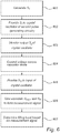
- calibration/regulation of the frequency difference is performed in steps 601-604 when the radar level gauge system is in its first state, and a measurement sweep is performed in steps 605-607 when the radar level gauge system is in its second state. These sets of steps may be performed in succession as is indicated in fig 6 , or several measurement sweeps may be performed after one calibration/regulation operation.
- a first signal S 1 is generated by the first pulse generator. This first signal S 1 is provided to the input 33 of the crystal oscillator 32 in the subsequent step 602. Thereafter, in step 603, the output S 2 from the crystal oscillator 32 is monitored, and the voltage over the capacitor diode 36 in the second pulse generating circuitry 25 is controlled in step 604 to control the time delay t d between the signals S 1 , S 2 to the desired time delay t d,desired that corresponds to the predetermined frequency difference ⁇ f.
- step 605 the radar level gauge system is controlled to its second state and the output signal S 2 from the crystal oscillator 32 is provided to the input 33 of the crystal oscillator 32 while maintaining the voltage across the capacitor diode 36. Thereafter, the reflected signal S R and the reference signal S REF output by the second pulse generating circuitry 25 are time correlated in the mixer 26 in step 606. Finally, in step 607, the filling level is determined by the processing circuitry based on the result of the time correlation.
Landscapes
- Engineering & Computer Science (AREA)
- Radar, Positioning & Navigation (AREA)
- Remote Sensing (AREA)
- Physics & Mathematics (AREA)
- General Physics & Mathematics (AREA)
- Computer Networks & Wireless Communication (AREA)
- Electromagnetism (AREA)
- Fluid Mechanics (AREA)
- Signal Processing (AREA)
- Thermal Sciences (AREA)
- Measurement Of Levels Of Liquids Or Fluent Solid Materials (AREA)
- Radar Systems Or Details Thereof (AREA)
Claims (15)
- Verfahren zum Bestimmen eines Füllstandes eines Produktes (6), das in einem Tank (5) enthalten ist, unter Verwendung eines Radar-Füllstandsmesssystems (1), wobei das Verfahren folgende Schritte umfasst:Erzeugen (601) eines Transmissionssignals (ST) unter Verwendung von ersten Impulserzeugungsschaltkreisen (20), die ein erstes Signal (S1) erzeugen, das eine erste Oszillationsfrequenz hat, wobei das Transmissionssignal die Form einer ersten Impulsfolge hat, die eine erste Impuls-Wiederholungsfrequenz hat;unter Verwendung von zweiten Impulserzeugungsschaltkreisen (25), die ein Resonatorelement (32) umfassen, das einen Eingang (33) und einen Ausgang (34) hat, Erzeugen eines Referenzsignals (SREF) in Form einer zweiten Impulsfolge, die eine zweite Impuls-Wiederholungsfrequenz hat, wobei die zweite Impuls-Wiederholungsfrequenz sich von der ersten Impuls-Wiederholungsfrequenz durch eine vorgegebene Frequenzdifferenz unterscheidet;Übertragen des Transmissionssignals (ST) auf eine Oberfläche (7) des Produktes, das im Tank enthalten ist;Empfangen eines reflektierten Signals (SR), das aus der Reflexion des Transmissionssignals an der Oberfläche des Produktes resultiert;Bilden (605) eines Messsignals, das eine Folge von Werten umfasst, wobei jeder Wert eine Zeitkorrelation zwischen einem Impuls des Referenzsignals und des reflektierten Signals repräsentiert; undBestimmen (607) des Füllstandes auf der Basis des Messsignals, dadurch gekennzeichnet, dass der Schritt des Erzeugens des Referenzsignals (SREF) die folgenden Schritte umfasst:Bereitstellen (602) des ersten Signals (S1) für den Eingang (33) des Resonatorelementes (32), das in der zweiten Impulserzeugungsschaltung (25) enthalten ist;Überwachen (603) eines Ausgangssignals vom Resonatorelement (32), wobei das Ausgangssignal im Wesentlichen dem ersten Signal entspricht, das durch eine Zeitverzögerung verzögert ist;Regulieren (604) von mindestens einem Parameter der zweiten Impulserzeugungsschaltung (25) auf einen Parameterwert, der zu der Zeitverzögerung führt, die der vorgegebenen Frequenzdifferenz entspricht; undSchalten des Radar-Füllstands-Messsystems zum Abschalten des ersten Signals (S1) vom Eingang (33) des Resonatorelementes und stattdessen Bereitstellen (605) des Ausgangssignals vom Resonatorelement (32) am Eingang des Resonatorelementes, während der Parameterwert des mindestens einen Parameters aufrechterhalten wird, wodurch das Referenzsignal (SREF) erzeugt wird.
- Verfahren nach Anspruch 1, wobei der Schritt des Kontrollierens den folgenden Schritt umfasst:
Steuern einer reaktiven Last über dem Resonatorelement (32), das in der zweiten Impulserzeugungsschaltung (25) enthalten ist. - Verfahren nach Anspruch 2, wobei die zweite Impulserzeugungsschaltung (25) einen spannungsgesteuerten Kondensator (36) umfasst, und der Schritt des Kontrollierens der reaktiven Last umfasst den folgenden Schritt:
Steuern einer Spannung, die an den spannungsgesteuerten Kondensator angelegt wird. - Verfahren nach einem der Ansprüche 1 bis 3, das ferner den Schritt des Verzögerns von mindestens einem Element aus dem Transmissionssignal (ST) und dem Referenzsignal (SREF) umfasst.
- Verfahren nach Anspruch 4, wobei das Transmissionssignal (ST) derart verzögert wird, dass ein erster Impuls in der ersten Impulsfolge zu einer späteren Zeit auftritt als ein erster Impuls in der zweiten Impulsfolge.
- Verfahren nach Anspruch 4, wobei das Referenzsignal (SREF) derart verzögert wird, dass ein erster Impuls in der zweiten Impulsfolge später auftritt als ein erster Impuls in der ersten Impulsfolge.
- Radar-Füllstandsmesssystem (1) zum Bestimmung eines Füllstandes eines Produktes (6), das sich in einem Tank (5) befindet, wobei das Radar-Füllstandsmesssystem Folgendes umfasst:erste Impulserzeugungsschaltkreise (20), die einen Ausgang zum Ausgeben eines ersten Signals (S1) haben, das eine erste Oszillationsfrequenz hat, zum Erzeugen eines Transmissionssignals (ST) in Form einer ersten Impulsfolge, die eine erste Impuls-Wiederholungsfrequenz hat;zweite Pulserzeugungsschaltkreise (25), die ein Resonatorelement (32) umfassen, das einen Eingang (33) und einen Ausgang (34) hat, zum Erzeugen eines Referenzsignals (SREF) in Form einer zweiten Impulsfolge, die eine zweite Impuls-Wiederholungsfrequenz hat, wobei die zweite Impuls-Wiederholungsfrequenz von der ersten Impuls-Wiederholungsfrequenz um eine vorgegebene Frequenzdifferenz abweicht;eine Ausbreitungsvorrichtung, die mit den ersten Impulserzeugungsschaltkreisen (20) verbunden ist und zum Ausbreiten des Übertragungssignals (ST) auf eine Oberfläche (7) des Produktes innerhalb des Tanks und zum Rückführen eines reflektierten Signals angeordnet ist, welches aus der Reflexion des Übertragungssignals an der Oberfläche des Produktes resultiert, das im Tank enthalten ist;Messschaltkreise (26), die mit der Ausbreitungsvorrichtung verbunden sind und mit den zweiten Impulserzeugungsschaltkreisen (25) verbunden werden können, wobei die Messschaltkreise dafür ausgelegt sind, ein Messsignal zu bilden, das eine Folge von Werten umfasst, wobei jeder Wert eine Zeitkorrelation zwischen einem Impuls des Referenzsignals und dem reflektierten Signal repräsentiert; undVerarbeitungsschaltkreise, die mit den Messschaltkreisen zum Bestimmen eines Füllstandes auf der Basis des Messsignals verbunden sind,dadurch gekennzeichnet, dass das Radar-Füllstandsmesssystem ferner umfasst:
ein Schaltelement (28), das so gesteuert werden kann, dass es das Radar-Füllstandsmesssystem umschaltet zwischen:einem ersten Zustand (Zustand 1) zum Kalibrieren der Frequenzdifferenz, bei der der Ausgang der ersten Impulserzeugungsschaltkreise (20) mit dem Eingang (33) des Resonatorelementes (32) verbunden ist, das in den zweiten Impulserzeugungsschaltkreisen (25) enthalten ist; undeinem zweiten Zustand (Zustand 2) für die Messung des Füllstandes, bei dem der Ausgang (34) des Resonatorelementes (32), das in den zweiten Impulserzeugungsschaltkreisen enthalten ist, mit dem Eingang (33) des Resonatorelementes, das in den zweiten Impulserzeugungsschaltkreisen enthalten ist, und den Messschaltkreisen verbunden ist;Überwachungsschaltkreise, die zum Überwachen einer Zeitverzögerung des Ausgangssignals aus dem Resonatorelement gegenüber dem ersten Signal ausgelegt sind, wenn das Radar-Füllstandsmesssystem im ersten Zustand ist; undeine Kontrolleinheit (30), die zum Steuern von mindestens einem Parameter der zweiten Impulserzeugungsschaltkreise (25) auf einen Parameterwert ausgelegt ist, der in der Zeitverzögerung resultiert, die der vorgegebenen Frequenzdifferenz entspricht. - Radar-Füllstandsmesssystem (1) nach Anspruch 7, wobei die Kontrolleinheit (30) ferner dafür ausgelegt ist, den Parameterwert aufrechtzuerhalten, wenn das Radar-Füllstandsmesssystem im zweiten Zustand ist (Zustand 2), um dadurch die vorgegebene Frequenzdifferenz zu erreichen.
- Radar-Füllstandsmesssystem (1) nach Anspruch 7 oder 8, wobei die zweiten Impulserzeugungsschaltkreise (25) eine steuerbare reaktive Last (36) über dem Resonatorelement umfassen.
- Radar-Füllstandsmesssystem (1) nach Anspruch 9, das ferner umfasst:Überwachen der Schaltkreise, die zum Überwachen einer Zeitverzögerung des Ausgangssignals vom Resonatorelement relativ zum ersten Signal ausgelegt sind, wenn das Radar-Füllstandsmesssystem im ersten Zustand ist;eine Kontrolleinheit (30), die dafür ausgelegt ist, zumindest die reaktive Last (36) über dem Resonatorelement auf einen Wert der reaktiven Last zu steuern, der zur Zeitverzögerung führt, die der vorgegebenen Frequenzdifferenz entspricht.
- Radar-Füllstandsmesssystem (1) nach Anspruch 9 oder 10, wobei die steuerbare reaktive Last einen spannungsgesteuerten Kondensator (36) umfasst.
- Radar-Füllstandsmesssystem (1) nach einem der Ansprüche 7 bis 11, das ferner eine Verzögerungsvorrichtung (21) umfasst, die zwischen den ersten Impulserzeugungsschaltkreisen und der Übertragungsvorrichtung zum Verzögern des Transmissionssignals angeordnet ist, bevor das Transmissionssignal zur Oberfläche des Produktes, das im Tank enthalten ist, übertragen wird.
- Radar-Füllstandsmesssystem (1) nach einem der Ansprüche 7 bis 11, das ferner eine Verzögerungsvorrichtung umfasst, die zwischen den zweiten Impulserzeugungsschaltkreisen und den Messschaltkreisen zum Verzögern des Referenzsignals angeordnet ist.
- Radar-Füllstandsmesssystem (1) nach einem der Ansprüche 7 bis 13, wobei:im ersten Zustand (Zustand 1) der Ausgang (34) des Resonatorelementes, das in den zweiten Impulserzeugungsschaltkreisen enthalten ist, nicht mit dem Eingang (33) des Resonatorelementes verbunden ist, das in den zweiten Impulserzeugungsschaltkreisen enthalten ist; undim zweiten Zustand (Zustand 2) der Ausgang der ersten Impulserzeugungsschaltkreise (20) nicht mit dem Eingang (33) des Resonatorelementes verbunden ist, das in den zweiten Impulserzeugungsschaltkreisen enthalten ist.
- Radar-Füllstandsmesssystem (1) nach einem der Ansprüche 7 bis 14, wobei das Resonatorelement (32) einen Kristall enthält, der eine vorgegebene Resonanzfrequenz hat.
Applications Claiming Priority (2)
| Application Number | Priority Date | Filing Date | Title |
|---|---|---|---|
| US12/636,890 US8044844B2 (en) | 2009-12-14 | 2009-12-14 | Pulsed radar level gauge system and method for energy efficient filling level determination |
| PCT/SE2010/051371 WO2011075051A1 (en) | 2009-12-14 | 2010-12-13 | Pulsed radar level gauge system and method for energy efficient filling level determination |
Publications (3)
| Publication Number | Publication Date |
|---|---|
| EP2513615A1 EP2513615A1 (de) | 2012-10-24 |
| EP2513615A4 EP2513615A4 (de) | 2015-06-17 |
| EP2513615B1 true EP2513615B1 (de) | 2018-11-07 |
Family
ID=44142326
Family Applications (1)
| Application Number | Title | Priority Date | Filing Date |
|---|---|---|---|
| EP10837979.3A Active EP2513615B1 (de) | 2009-12-14 | 2010-12-13 | Radarfüllstandsmesssystem und zugehöriges verfahren |
Country Status (4)
| Country | Link |
|---|---|
| US (1) | US8044844B2 (de) |
| EP (1) | EP2513615B1 (de) |
| CN (1) | CN102362158B (de) |
| WO (1) | WO2011075051A1 (de) |
Cited By (1)
| Publication number | Priority date | Publication date | Assignee | Title |
|---|---|---|---|---|
| WO2025103659A1 (de) * | 2023-11-17 | 2025-05-22 | Endress+Hauser SE+Co. KG | Füllstandsmessgerät |
Families Citing this family (28)
| Publication number | Priority date | Publication date | Assignee | Title |
|---|---|---|---|---|
| GB0705449D0 (en) * | 2007-03-22 | 2007-05-02 | Siemens Milltronics Proc Instr | A high frequency radar system |
| CA2739362A1 (en) * | 2011-05-06 | 2012-11-06 | Gotohti.Com Inc. | Fluid level gauge |
| AT508369B1 (de) | 2009-06-17 | 2011-01-15 | Vatron Gmbh | Verfahren und vorrichtung zur berechnung einer oberfläche eines füllguts eines behälters |
| US8044844B2 (en) * | 2009-12-14 | 2011-10-25 | Rosemount Tank Radar Ab | Pulsed radar level gauge system and method for energy efficient filling level determination |
| US9513153B2 (en) | 2010-12-30 | 2016-12-06 | Rosemount Tank Radar Ab | Radar level gauging using frequency modulated pulsed wave |
| US20130057425A1 (en) * | 2011-09-06 | 2013-03-07 | Fabian Wenger | Pulsed level gauge system with controllable delay path through selected number of delay cells |
| US8854253B2 (en) * | 2011-09-27 | 2014-10-07 | Rosemount Tank Radar Ab | Radar level gauging with detection of moving surface |
| US9035822B2 (en) * | 2012-06-18 | 2015-05-19 | Rosemount Tank Radar Ab | Intermittent filling level determination with dynamically determined number of measurements |
| US8844352B2 (en) | 2012-06-18 | 2014-09-30 | Rosemount Tank Radar Ab | Pulsed level gauge system with adaptive transceiver control |
| US9989628B2 (en) * | 2012-06-29 | 2018-06-05 | Rosemount Tank Radar Ab | Pulsed level gauge system with temperature-based control of pulse repetition frequency |
| DE102013114735A1 (de) * | 2013-12-20 | 2015-06-25 | Endress + Hauser Gmbh + Co. Kg | PRF-Frequenzgenerator für ein Füllstandsmessgerät |
| WO2015124201A1 (de) * | 2014-02-21 | 2015-08-27 | Vega Grieshaber Kg | Füllstandmessgerät mit optimierter energieversorgung |
| US9593976B2 (en) * | 2014-05-19 | 2017-03-14 | Rosemount Tank Radar Ab | Pulsed level gauge system and method |
| US9709433B2 (en) * | 2014-06-30 | 2017-07-18 | Rosemount Tank Radar Ab | Pulsed radar level gauging with efficient start-up |
| US9746366B2 (en) * | 2014-12-01 | 2017-08-29 | Rosemount Tank Radar Ab | Radar level gauging |
| US10130221B2 (en) | 2015-01-23 | 2018-11-20 | Gpcp Ip Holdings Llc | Optimizing a dispensing parameter of a product dispenser based on product usage data |
| US9618617B2 (en) * | 2015-03-20 | 2017-04-11 | Honeywell International Inc. | Level measurement using correlation between a pair of secondary reference signals |
| US20170123092A1 (en) * | 2015-10-30 | 2017-05-04 | Indiana University Research And Technology Corporation | Systems and methods for detection of well properties |
| US11395566B2 (en) | 2016-04-11 | 2022-07-26 | Gpcp Ip Holdings Llc | Sheet product dispenser |
| US11412900B2 (en) | 2016-04-11 | 2022-08-16 | Gpcp Ip Holdings Llc | Sheet product dispenser with motor operation sensing |
| US10874265B2 (en) | 2017-05-10 | 2020-12-29 | Gpcp Ip Holdings Llc | Sheet product level sensor calibration and indication systems and methods |
| DE102017123185A1 (de) * | 2017-10-05 | 2019-04-11 | Krohne S. A. S. | Verfahren und Füllstandmessgerät zur Bestimmung des Füllstandes eines Mediums mittels Dauerstrich-Radarmessung |
| DE102018104729B4 (de) * | 2018-03-01 | 2024-06-27 | Infineon Technologies Ag | Verfahren und Vorrichtungen zum Prüfen eines oder mehrerer Empfangspfade in einem Radarempfänger |
| US11079473B2 (en) | 2019-04-01 | 2021-08-03 | Abb Schweiz Ag | Timing control circuit for guided wave radar level transmitter |
| US11193809B2 (en) | 2019-04-01 | 2021-12-07 | Abb Schweiz Ag | Expert control systems and methods for level measurement |
| US11415451B2 (en) | 2019-04-01 | 2022-08-16 | Abb Schweiz Ag | High and/or low energy system coupler |
| US11617478B2 (en) | 2019-10-09 | 2023-04-04 | Gpcp Ip Holdings Llc | Systems and methods for product level tracking of sheet product rolls |
| CN110567557B (zh) * | 2019-10-30 | 2024-10-11 | 北京锐达仪表有限公司 | 一种用于测量容器内物料物位的脉冲雷达物位计 |
Family Cites Families (26)
| Publication number | Priority date | Publication date | Assignee | Title |
|---|---|---|---|---|
| DE2544842A1 (de) | 1975-10-07 | 1977-04-21 | Bosch Gmbh Robert | Verfahren und schaltungsanordnung zum auswerten von signalimpulsfolgen, insbesondere radar-impulsfolgen |
| US5457990A (en) | 1991-12-03 | 1995-10-17 | Cambridge Consultants Limited | Method and apparatus for determining a fluid level in the vicinity of a transmission line |
| DE4219990A1 (de) | 1992-06-19 | 1993-12-23 | Thomson Brandt Gmbh | Oszillatorschaltung und deren Verwendung |
| JP3681529B2 (ja) * | 1997-12-26 | 2005-08-10 | 日本ジーイープラスチックス株式会社 | ポリカーボネートの製造方法 |
| EP0955527B1 (de) * | 1998-05-05 | 2007-06-27 | Endress + Hauser GmbH + Co. KG | Mit Mikrowellen arbeitendes Füllstandsmessgerät |
| DE29815069U1 (de) * | 1998-08-25 | 1998-12-24 | Vega Grieshaber Kg, 77709 Wolfach | Sampling-Schaltung zur Abtastung von Hochfrequenzsignalpulsen für die Verwendung in TDR-Füllstandssensoren |
| US6072427A (en) | 1999-04-01 | 2000-06-06 | Mcewan; Thomas E. | Precision radar timebase using harmonically related offset oscillators |
| US6373428B1 (en) | 1999-04-01 | 2002-04-16 | Mcewan Technologies, Llc | Self locking dual frequency clock system |
| US6300897B1 (en) * | 1999-07-02 | 2001-10-09 | Rosemount Inc. | Stabilization in a radar level gauge |
| DE19952826C1 (de) | 1999-11-03 | 2001-04-12 | Krohne Sa | Zeitbasisgenerator |
| US6679115B2 (en) * | 2001-02-14 | 2004-01-20 | Endress + Hauser Gmbh + Co. | Apparatus for determining the filling level of a product in a container |
| JP3774128B2 (ja) | 2001-05-28 | 2006-05-10 | 有限会社 マイクロウェーブラボ | タイミングパルス発生回路 |
| US6628229B1 (en) | 2002-08-01 | 2003-09-30 | Rosemount Inc. | Stabilization of oscillators in a radar level transmitter |
| CA2425250A1 (en) * | 2003-04-11 | 2004-10-11 | Quinton Lyon | Time-base generator with self-compensating control loop |
| JP2005156393A (ja) | 2003-11-27 | 2005-06-16 | Mitsubishi Electric Corp | レーダ装置 |
| DE10360711A1 (de) * | 2003-12-19 | 2005-07-14 | Endress + Hauser Gmbh + Co. Kg | Füllstandsmeßgerät und Verfahren zur Füllstandsmessung und -überwachung |
| DE102004004707A1 (de) | 2004-01-30 | 2005-08-18 | Robert Bosch Gmbh | Kapazitätsdioden-Alternativschaltung |
| DE102004032130B4 (de) | 2004-07-01 | 2010-12-16 | Krohne Messtechnik Gmbh | Frequenzsynthesizer und Verfahren zum Betrieb eines Frequenzsynthesizers |
| US7131325B2 (en) | 2004-07-01 | 2006-11-07 | Saab Rosemount Tank Radar Ab | Radar level gauge system with intermittent amplification |
| KR100640517B1 (ko) | 2005-05-18 | 2006-10-30 | 삼성전기주식회사 | 전력 절약용 전압제어발진기 |
| US7412337B2 (en) * | 2005-10-13 | 2008-08-12 | Endress + Hauser Gmbh + Co. Kg | Method for determining fill level on the basis of travel time of a high-frequency measuring signal |
| DE102006034554A1 (de) | 2006-07-26 | 2008-01-31 | Vega Grieshaber Kg | Unabhängige Referenzpulserzeugung |
| US7823446B2 (en) | 2006-11-06 | 2010-11-02 | Rosemount Tank Radar Ab | Pulsed radar level gauging with relative phase detection |
| DE602007010942D1 (de) * | 2007-09-28 | 2011-01-13 | Siemens Milltronics Proc Instr | Impulsradarsystem |
| EP2068169B1 (de) * | 2007-12-06 | 2012-01-25 | Siemens Aktiengesellschaft | Impulsradarbewertungssystem |
| US8044844B2 (en) * | 2009-12-14 | 2011-10-25 | Rosemount Tank Radar Ab | Pulsed radar level gauge system and method for energy efficient filling level determination |
-
2009
- 2009-12-14 US US12/636,890 patent/US8044844B2/en active Active
-
2010
- 2010-12-13 WO PCT/SE2010/051371 patent/WO2011075051A1/en not_active Ceased
- 2010-12-13 CN CN201080013584.6A patent/CN102362158B/zh active Active
- 2010-12-13 EP EP10837979.3A patent/EP2513615B1/de active Active
Non-Patent Citations (1)
| Title |
|---|
| None * |
Cited By (1)
| Publication number | Priority date | Publication date | Assignee | Title |
|---|---|---|---|---|
| WO2025103659A1 (de) * | 2023-11-17 | 2025-05-22 | Endress+Hauser SE+Co. KG | Füllstandsmessgerät |
Also Published As
| Publication number | Publication date |
|---|---|
| EP2513615A4 (de) | 2015-06-17 |
| WO2011075051A1 (en) | 2011-06-23 |
| US8044844B2 (en) | 2011-10-25 |
| CN102362158A (zh) | 2012-02-22 |
| EP2513615A1 (de) | 2012-10-24 |
| US20110140951A1 (en) | 2011-06-16 |
| CN102362158B (zh) | 2014-09-24 |
Similar Documents
| Publication | Publication Date | Title |
|---|---|---|
| US8044844B2 (en) | Pulsed radar level gauge system and method for energy efficient filling level determination | |
| US8223066B2 (en) | Pulsed radar level gauge system and method with reduced start-up time | |
| US7412337B2 (en) | Method for determining fill level on the basis of travel time of a high-frequency measuring signal | |
| EP2680027B1 (de) | Gepulstes Pegelmesssystem mit temperaturbasierter Steuerung der Impulsfolgefrequenz | |
| US8686895B2 (en) | Pulsed radar level gauge system with higher order harmonic regulation | |
| US9024806B2 (en) | Radar level gauge with MCU timing circuit | |
| KR102331740B1 (ko) | 주파수 변조형 레이더 레벨 게이지 | |
| EP2947428B1 (de) | Gepulstes füllstandsanzeigersystem und verfahren | |
| US20180328771A1 (en) | Pulsed radar level gauge system and method for reduced relative bandwidth | |
| US20120056628A1 (en) | Propagation Time Measuring Method for Determining a Distance | |
| EP3201579A1 (de) | Auflösungsmodusumschaltung für pulsradar | |
| US20130057425A1 (en) | Pulsed level gauge system with controllable delay path through selected number of delay cells | |
| CN112689744B (zh) | 料位测量装置 | |
| US20130057426A1 (en) | Pulsed level gauge system with supply voltage controlled delay | |
| EP3479137B1 (de) | Fmcw-radar-füllstandsmesser mit verbesserter zeitsteuerung | |
| CN113272630B (zh) | 填充水平测量设备 | |
| EP3301472B1 (de) | Gepulstes radarfüllstandmessgerät mit einzeloszillator | |
| WO2018060352A1 (en) | Pulsed radar level gauge with single oscillator |
Legal Events
| Date | Code | Title | Description |
|---|---|---|---|
| PUAI | Public reference made under article 153(3) epc to a published international application that has entered the european phase |
Free format text: ORIGINAL CODE: 0009012 |
|
| 17P | Request for examination filed |
Effective date: 20120507 |
|
| AK | Designated contracting states |
Kind code of ref document: A1 Designated state(s): AL AT BE BG CH CY CZ DE DK EE ES FI FR GB GR HR HU IE IS IT LI LT LU LV MC MK MT NL NO PL PT RO RS SE SI SK SM TR |
|
| DAX | Request for extension of the european patent (deleted) | ||
| RA4 | Supplementary search report drawn up and despatched (corrected) |
Effective date: 20150520 |
|
| RIC1 | Information provided on ipc code assigned before grant |
Ipc: G01S 7/285 20060101ALI20150513BHEP Ipc: G01F 23/00 20060101AFI20150513BHEP Ipc: G01S 7/40 20060101ALI20150513BHEP Ipc: G01S 7/28 20060101ALI20150513BHEP Ipc: G01S 7/491 20060101ALI20150513BHEP Ipc: G01F 23/284 20060101ALI20150513BHEP Ipc: G01S 13/10 20060101ALI20150513BHEP Ipc: G01S 13/88 20060101ALI20150513BHEP |
|
| REG | Reference to a national code |
Ref country code: DE Ref legal event code: R079 Ref document number: 602010054998 Country of ref document: DE Free format text: PREVIOUS MAIN CLASS: G01F0023284000 Ipc: G01F0023000000 |
|
| RIC1 | Information provided on ipc code assigned before grant |
Ipc: G01F 23/284 20060101ALI20180426BHEP Ipc: G01S 7/40 20060101ALI20180426BHEP Ipc: G01S 7/285 20060101ALI20180426BHEP Ipc: G01S 13/10 20060101ALI20180426BHEP Ipc: G01S 7/491 20060101ALI20180426BHEP Ipc: G01F 23/00 20060101AFI20180426BHEP Ipc: G01S 7/35 20060101ALI20180426BHEP Ipc: G01S 13/88 20060101ALI20180426BHEP Ipc: G01S 7/28 20060101ALI20180426BHEP Ipc: G01S 13/32 20060101ALI20180426BHEP |
|
| GRAP | Despatch of communication of intention to grant a patent |
Free format text: ORIGINAL CODE: EPIDOSNIGR1 |
|
| INTG | Intention to grant announced |
Effective date: 20180615 |
|
| GRAS | Grant fee paid |
Free format text: ORIGINAL CODE: EPIDOSNIGR3 |
|
| GRAA | (expected) grant |
Free format text: ORIGINAL CODE: 0009210 |
|
| AK | Designated contracting states |
Kind code of ref document: B1 Designated state(s): AL AT BE BG CH CY CZ DE DK EE ES FI FR GB GR HR HU IE IS IT LI LT LU LV MC MK MT NL NO PL PT RO RS SE SI SK SM TR |
|
| REG | Reference to a national code |
Ref country code: GB Ref legal event code: FG4D |
|
| REG | Reference to a national code |
Ref country code: CH Ref legal event code: EP Ref country code: AT Ref legal event code: REF Ref document number: 1062611 Country of ref document: AT Kind code of ref document: T Effective date: 20181115 |
|
| REG | Reference to a national code |
Ref country code: IE Ref legal event code: FG4D |
|
| REG | Reference to a national code |
Ref country code: DE Ref legal event code: R096 Ref document number: 602010054998 Country of ref document: DE |
|
| REG | Reference to a national code |
Ref country code: CH Ref legal event code: NV Representative=s name: OFFICE ERNEST T. FREYLINGER S.A., CH Ref country code: CH Ref legal event code: PCOW Free format text: NEW ADDRESS: BOX 150, 435 23 MOELNLYCKE (SE) |
|
| REG | Reference to a national code |
Ref country code: NL Ref legal event code: MP Effective date: 20181107 |
|
| REG | Reference to a national code |
Ref country code: LT Ref legal event code: MG4D |
|
| REG | Reference to a national code |
Ref country code: AT Ref legal event code: MK05 Ref document number: 1062611 Country of ref document: AT Kind code of ref document: T Effective date: 20181107 |
|
| PG25 | Lapsed in a contracting state [announced via postgrant information from national office to epo] |
Ref country code: HR Free format text: LAPSE BECAUSE OF FAILURE TO SUBMIT A TRANSLATION OF THE DESCRIPTION OR TO PAY THE FEE WITHIN THE PRESCRIBED TIME-LIMIT Effective date: 20181107 Ref country code: NO Free format text: LAPSE BECAUSE OF FAILURE TO SUBMIT A TRANSLATION OF THE DESCRIPTION OR TO PAY THE FEE WITHIN THE PRESCRIBED TIME-LIMIT Effective date: 20190207 Ref country code: LV Free format text: LAPSE BECAUSE OF FAILURE TO SUBMIT A TRANSLATION OF THE DESCRIPTION OR TO PAY THE FEE WITHIN THE PRESCRIBED TIME-LIMIT Effective date: 20181107 Ref country code: AT Free format text: LAPSE BECAUSE OF FAILURE TO SUBMIT A TRANSLATION OF THE DESCRIPTION OR TO PAY THE FEE WITHIN THE PRESCRIBED TIME-LIMIT Effective date: 20181107 Ref country code: ES Free format text: LAPSE BECAUSE OF FAILURE TO SUBMIT A TRANSLATION OF THE DESCRIPTION OR TO PAY THE FEE WITHIN THE PRESCRIBED TIME-LIMIT Effective date: 20181107 Ref country code: IS Free format text: LAPSE BECAUSE OF FAILURE TO SUBMIT A TRANSLATION OF THE DESCRIPTION OR TO PAY THE FEE WITHIN THE PRESCRIBED TIME-LIMIT Effective date: 20190307 Ref country code: BG Free format text: LAPSE BECAUSE OF FAILURE TO SUBMIT A TRANSLATION OF THE DESCRIPTION OR TO PAY THE FEE WITHIN THE PRESCRIBED TIME-LIMIT Effective date: 20190207 Ref country code: LT Free format text: LAPSE BECAUSE OF FAILURE TO SUBMIT A TRANSLATION OF THE DESCRIPTION OR TO PAY THE FEE WITHIN THE PRESCRIBED TIME-LIMIT Effective date: 20181107 Ref country code: FI Free format text: LAPSE BECAUSE OF FAILURE TO SUBMIT A TRANSLATION OF THE DESCRIPTION OR TO PAY THE FEE WITHIN THE PRESCRIBED TIME-LIMIT Effective date: 20181107 |
|
| PG25 | Lapsed in a contracting state [announced via postgrant information from national office to epo] |
Ref country code: GR Free format text: LAPSE BECAUSE OF FAILURE TO SUBMIT A TRANSLATION OF THE DESCRIPTION OR TO PAY THE FEE WITHIN THE PRESCRIBED TIME-LIMIT Effective date: 20190208 Ref country code: RS Free format text: LAPSE BECAUSE OF FAILURE TO SUBMIT A TRANSLATION OF THE DESCRIPTION OR TO PAY THE FEE WITHIN THE PRESCRIBED TIME-LIMIT Effective date: 20181107 Ref country code: SE Free format text: LAPSE BECAUSE OF FAILURE TO SUBMIT A TRANSLATION OF THE DESCRIPTION OR TO PAY THE FEE WITHIN THE PRESCRIBED TIME-LIMIT Effective date: 20181107 Ref country code: AL Free format text: LAPSE BECAUSE OF FAILURE TO SUBMIT A TRANSLATION OF THE DESCRIPTION OR TO PAY THE FEE WITHIN THE PRESCRIBED TIME-LIMIT Effective date: 20181107 Ref country code: PT Free format text: LAPSE BECAUSE OF FAILURE TO SUBMIT A TRANSLATION OF THE DESCRIPTION OR TO PAY THE FEE WITHIN THE PRESCRIBED TIME-LIMIT Effective date: 20190307 Ref country code: NL Free format text: LAPSE BECAUSE OF FAILURE TO SUBMIT A TRANSLATION OF THE DESCRIPTION OR TO PAY THE FEE WITHIN THE PRESCRIBED TIME-LIMIT Effective date: 20181107 |
|
| PG25 | Lapsed in a contracting state [announced via postgrant information from national office to epo] |
Ref country code: PL Free format text: LAPSE BECAUSE OF FAILURE TO SUBMIT A TRANSLATION OF THE DESCRIPTION OR TO PAY THE FEE WITHIN THE PRESCRIBED TIME-LIMIT Effective date: 20181107 Ref country code: DK Free format text: LAPSE BECAUSE OF FAILURE TO SUBMIT A TRANSLATION OF THE DESCRIPTION OR TO PAY THE FEE WITHIN THE PRESCRIBED TIME-LIMIT Effective date: 20181107 Ref country code: IT Free format text: LAPSE BECAUSE OF FAILURE TO SUBMIT A TRANSLATION OF THE DESCRIPTION OR TO PAY THE FEE WITHIN THE PRESCRIBED TIME-LIMIT Effective date: 20181107 Ref country code: CZ Free format text: LAPSE BECAUSE OF FAILURE TO SUBMIT A TRANSLATION OF THE DESCRIPTION OR TO PAY THE FEE WITHIN THE PRESCRIBED TIME-LIMIT Effective date: 20181107 |
|
| REG | Reference to a national code |
Ref country code: DE Ref legal event code: R097 Ref document number: 602010054998 Country of ref document: DE |
|
| PG25 | Lapsed in a contracting state [announced via postgrant information from national office to epo] |
Ref country code: MC Free format text: LAPSE BECAUSE OF FAILURE TO SUBMIT A TRANSLATION OF THE DESCRIPTION OR TO PAY THE FEE WITHIN THE PRESCRIBED TIME-LIMIT Effective date: 20181107 Ref country code: LU Free format text: LAPSE BECAUSE OF NON-PAYMENT OF DUE FEES Effective date: 20181213 Ref country code: RO Free format text: LAPSE BECAUSE OF FAILURE TO SUBMIT A TRANSLATION OF THE DESCRIPTION OR TO PAY THE FEE WITHIN THE PRESCRIBED TIME-LIMIT Effective date: 20181107 Ref country code: SM Free format text: LAPSE BECAUSE OF FAILURE TO SUBMIT A TRANSLATION OF THE DESCRIPTION OR TO PAY THE FEE WITHIN THE PRESCRIBED TIME-LIMIT Effective date: 20181107 Ref country code: EE Free format text: LAPSE BECAUSE OF FAILURE TO SUBMIT A TRANSLATION OF THE DESCRIPTION OR TO PAY THE FEE WITHIN THE PRESCRIBED TIME-LIMIT Effective date: 20181107 Ref country code: SK Free format text: LAPSE BECAUSE OF FAILURE TO SUBMIT A TRANSLATION OF THE DESCRIPTION OR TO PAY THE FEE WITHIN THE PRESCRIBED TIME-LIMIT Effective date: 20181107 |
|
| PLBE | No opposition filed within time limit |
Free format text: ORIGINAL CODE: 0009261 |
|
| STAA | Information on the status of an ep patent application or granted ep patent |
Free format text: STATUS: NO OPPOSITION FILED WITHIN TIME LIMIT |
|
| REG | Reference to a national code |
Ref country code: IE Ref legal event code: MM4A |
|
| REG | Reference to a national code |
Ref country code: BE Ref legal event code: MM Effective date: 20181231 |
|
| 26N | No opposition filed |
Effective date: 20190808 |
|
| GBPC | Gb: european patent ceased through non-payment of renewal fee |
Effective date: 20190207 |
|
| PG25 | Lapsed in a contracting state [announced via postgrant information from national office to epo] |
Ref country code: IE Free format text: LAPSE BECAUSE OF NON-PAYMENT OF DUE FEES Effective date: 20181213 Ref country code: SI Free format text: LAPSE BECAUSE OF FAILURE TO SUBMIT A TRANSLATION OF THE DESCRIPTION OR TO PAY THE FEE WITHIN THE PRESCRIBED TIME-LIMIT Effective date: 20181107 Ref country code: FR Free format text: LAPSE BECAUSE OF NON-PAYMENT OF DUE FEES Effective date: 20190107 |
|
| PG25 | Lapsed in a contracting state [announced via postgrant information from national office to epo] |
Ref country code: BE Free format text: LAPSE BECAUSE OF NON-PAYMENT OF DUE FEES Effective date: 20181231 |
|
| PG25 | Lapsed in a contracting state [announced via postgrant information from national office to epo] |
Ref country code: MT Free format text: LAPSE BECAUSE OF NON-PAYMENT OF DUE FEES Effective date: 20181213 Ref country code: GB Free format text: LAPSE BECAUSE OF NON-PAYMENT OF DUE FEES Effective date: 20190207 |
|
| PG25 | Lapsed in a contracting state [announced via postgrant information from national office to epo] |
Ref country code: TR Free format text: LAPSE BECAUSE OF FAILURE TO SUBMIT A TRANSLATION OF THE DESCRIPTION OR TO PAY THE FEE WITHIN THE PRESCRIBED TIME-LIMIT Effective date: 20181107 |
|
| PG25 | Lapsed in a contracting state [announced via postgrant information from national office to epo] |
Ref country code: CY Free format text: LAPSE BECAUSE OF FAILURE TO SUBMIT A TRANSLATION OF THE DESCRIPTION OR TO PAY THE FEE WITHIN THE PRESCRIBED TIME-LIMIT Effective date: 20181107 Ref country code: MK Free format text: LAPSE BECAUSE OF NON-PAYMENT OF DUE FEES Effective date: 20181107 Ref country code: HU Free format text: LAPSE BECAUSE OF FAILURE TO SUBMIT A TRANSLATION OF THE DESCRIPTION OR TO PAY THE FEE WITHIN THE PRESCRIBED TIME-LIMIT; INVALID AB INITIO Effective date: 20101213 |
|
| PGFP | Annual fee paid to national office [announced via postgrant information from national office to epo] |
Ref country code: CH Payment date: 20240102 Year of fee payment: 14 |
|
| REG | Reference to a national code |
Ref country code: CH Ref legal event code: PL |
|
| PG25 | Lapsed in a contracting state [announced via postgrant information from national office to epo] |
Ref country code: CH Free format text: LAPSE BECAUSE OF NON-PAYMENT OF DUE FEES Effective date: 20241231 |
|
| PGFP | Annual fee paid to national office [announced via postgrant information from national office to epo] |
Ref country code: DE Payment date: 20251126 Year of fee payment: 16 |