EP2512902B1 - Fahrzeuganhänger mit einer zwangslenkung - Google Patents
Fahrzeuganhänger mit einer zwangslenkung Download PDFInfo
- Publication number
- EP2512902B1 EP2512902B1 EP10807311.5A EP10807311A EP2512902B1 EP 2512902 B1 EP2512902 B1 EP 2512902B1 EP 10807311 A EP10807311 A EP 10807311A EP 2512902 B1 EP2512902 B1 EP 2512902B1
- Authority
- EP
- European Patent Office
- Prior art keywords
- slave cylinder
- vehicle trailer
- steering
- cylinder
- steered axle
- Prior art date
- Legal status (The legal status is an assumption and is not a legal conclusion. Google has not performed a legal analysis and makes no representation as to the accuracy of the status listed.)
- Not-in-force
Links
Images

Classifications
-
- B—PERFORMING OPERATIONS; TRANSPORTING
- B62—LAND VEHICLES FOR TRAVELLING OTHERWISE THAN ON RAILS
- B62D—MOTOR VEHICLES; TRAILERS
- B62D13/00—Steering specially adapted for trailers
- B62D13/02—Steering specially adapted for trailers for centrally-pivoted axles
- B62D13/025—Steering specially adapted for trailers for centrally-pivoted axles the pivoted movement being initiated by the coupling means between tractor and trailer
-
- B—PERFORMING OPERATIONS; TRANSPORTING
- B62—LAND VEHICLES FOR TRAVELLING OTHERWISE THAN ON RAILS
- B62D—MOTOR VEHICLES; TRAILERS
- B62D13/00—Steering specially adapted for trailers
- B62D13/04—Steering specially adapted for trailers for individually-pivoted wheels
Definitions
- the invention relates to a vehicle trailer with a forced steering according to the preamble of claim 1.
- the wheel position forcibly depends on a length of at least one slave cylinder of the forced steering.
- the slave cylinder is controlled hydraulically and a master cylinder specifies the change in length of the slave cylinder.
- the wheel position follows the change in length of the slave cylinder, wherein the change in length of the slave cylinder causes the lateral deflection of the wheels of the steered axle about the steering axes of rotation of the wheels.
- the relationship between the change in length of the slave cylinder and the angular change in the steering position of the wheels of the steered axle is referred to as a transfer function of the steered axle.
- document DE 20 2004 000 605 U1 discloses the preamble of claim 1.
- the vehicle trailer is intended for attachment to a towing vehicle, in particular a tractor.
- the vehicle trailer and the towing vehicle form a train.
- the steering behavior of the towing vehicle and the steering behavior of the vehicle trailer are matched. If this is not the case, for example, if the towing vehicle of the train is changed, then the forced steering often works unsatisfactory or not.
- the object of the invention is therefore to provide a vehicle trailer of the type mentioned above, which ensures that the forced steering function reliably on different towing vehicles with different steering behavior and possibly necessary adjustments to the steering behavior of the vehicle trailer can be carried out easily and on site.
- the position of the effective axis and / or the distance between this point of application and the adjacent steering axis of rotation of the wheel is changed.
- the - conventionally fixed - transfer function of the steered axle can be changed specifiable, in particular can be adapted to a changed steering behavior of the towing vehicle.
- the advantage here is that the predetermined change in the transfer function of the steered axle without an intervention or exchange of Master cylinder or slave cylinder of the hydraulic system can be done.
- this change in the transfer function of the steered axle on the ground, including on the field or on the road, can be performed.
- the intervention or the replacement of master cylinder or slave cylinder of the hydraulic system due to the risk of contamination occurring by means of hydraulic oil - not easily done on the spot.
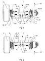
- the Fig. 1 to 7 show a particularly advantageous first and a particularly advantageous second embodiment of the steered axle 1 in detail from a vehicle trailer with a forced steering for steering the wheels of at least one steered axle 1, wherein the forced steering system is a hydraulic system with at least one master cylinder and at least one first slave cylinder 21 includes.
- the transfer function of the steered axle can be changed specifiable and so the steering behavior of the vehicle trailer can be adapted to different steering behavior different towing vehicles, it is proposed that at least the position of one of the points 3 of at least one first slave cylinder 21 transversely to the axis of action of the at least one first slave cylinder 21st
- an adjusting device 4 is changeable.
- the position of the active axis and / or the distance between just this point 3 and an adjacent to the point 3 steering axis of rotation 60 of a wheel 6 is changed.
- This has the advantage that the - conventionally fixed - transfer function of the steered axle 1 can be changed specifiable, in particular can be adapted to a changed steering behavior of the towing vehicle.
- the advantage here is that the predetermined change in the transfer function of the steered axle 1 can be done without an intervention or exchange of master cylinder or slave cylinder 21, 22 of the hydraulic system.
- the advantage here is that this change in the transfer function of the steered axle 1 on-site, including on the field or on the road, can be performed.
- Another advantage is that the steering behavior of the vehicle trailer - despite purely mechanical actuation of the master cylinder, ie without the aid of a computer-aided steering error compensation - can be adapted very precisely to different steering behavior different towing vehicles.
- the advantage here is that the forced steering of the vehicle trailer consumes no electricity and works reliably in case of failure of the on-board power supply system.
- the vehicle trailer can be designed cost-effectively, since without computer-aided steering error compensation, and thus can be used inexpensively.
- the first slave cylinder 21 comprises a hollow cylinder 24 and a piston rod 25, wherein the hollow cylinder 24 and the piston rod 25 to the length change of the slave cylinder 21 are mutually relatively movable.
- the steered axle 1 encompassed by the vehicle trailer comprises two wheels, a first wheel 6 and a second wheel (not shown).
- the hydraulic system furthermore comprises an operative connection between the master cylinder and the first slave cylinder 21.
- the operative connection can be formed in particular by means of hydraulic lines.
- Fig. 1 to 7 the steered axle 1 is shown in a straight ahead position.
- the steerable wheels of the steered axle 1 are rotatable about steering axes of rotation 60 of the steered axle 1.
- the steering pivot axes 60 are directed substantially normal to the direction of rotation of the wheels. In particular, when the vehicle trailer is on a horizontal plane, the steering pivots 60 may be arranged substantially vertically.
- the axis of action of the first slave cylinder 21 extends through the opposing engagement points 3 of the first slave cylinder 21.
- the first Slave cylinder 21 is variable in length along its longitudinal direction and the axis of action of the first slave cylinder 21 and the longitudinal direction of the first slave cylinder 21 are substantially parallel to each other.
- the engagement points 3 of the at least one first slave cylinder 21 are those points at which the first slave cylinder 21 is connected to other parts of the vehicle trailer, so that a change in length of the first slave cylinder 21, which causes a change in the distance between the two points 3 of the first slave cylinder 21, causes a steering of the wheels of the steered axle 1.
- the engagement points 3 of the at least one first slave cylinder 21 are connected to the other parts of the vehicle trailer by means of screw, pin and / or bolt connection.
- the longitudinal axis and effective axis of the at least one first slave cylinder 21 are substantially parallel to one another.
- the steered axle 1 steers in a first direction, for example to the left, wherein the first wheel 6 mounted on the steered axle 1 about a first steering axis of rotation 61 of two steering axes of rotation 60 of the steered axle 1 is rotated or mounted on the steered axle 1 second wheel is rotated about a second steering axis 62 of the two steering axes of rotation 60.
- the steered axle 1 steers in a direction opposite to the first direction, for example, to the right, the two wheels also around the first or the second steering rotation axis 61, 62 are rotated.
- the change in angle of the two wheels per change in length of the first slave cylinder 21 is the transfer function of the steered axle 1.
- the first slave cylinder 21 has a first engagement point 31 at a first of its two ends.
- the first point 31 of the at least one first slave cylinder 21 is connected to a steering lever 5 of a first wheel 6 of the steered axle 1 of the vehicle trailer.
- the position of the first point of application 31 is changeable transversely to the axis of action of the at least one first slave cylinder 21. If the position of the first point of application 31 is changed transversely to the axis of action of the at least one first slave cylinder 21, this changes the distance of the first point of application 31 to the adjacent first point Steering rotary axis 61.
- the first slave cylinder 21 has a second engagement point 32 at a second of its two ends.
- the first engagement point 31 opposite second point 32 of the at least one first slave cylinder 21 is arranged substantially stationary with respect to the vehicle trailer.
- the position of the second point of application 32 is changeable transversely to the axis of action of the at least one first slave cylinder 21. If the position of the second point of attack 32 transversely to the axis of action of the at least one first slave cylinder 21 is changed, this changes the distance of the second point of attack 31 to adjacent first steering axis of rotation 61 little, but changes the position of the axis of action of the at least one first slave cylinder 21.
- the transfer function of the steered axle 1 can also be changed, in particular, the linearity of the transfer function can be influenced.
- the first engagement point 31 is connected to the steering lever 5 of the first wheel 6, that the second engagement point 32 is arranged substantially stationary with respect to the vehicle trailer, and that both the position of the first Point of attack 31 and the position of the second point 32 by means of an adjusting device 4 transversely to the axis of action of the first slave cylinder 21 are changed.
- the advantage here is that the change in angle of the steered axle 1 per change in length of the slave cylinder 21 can be reduced or increased by changing the position of the first point of attack 31 and thereby possibly amplified non-linearity of the transfer function by appropriately moving the position of the second attack point 32nd can be avoided such that the direction of action of the first slave cylinder 21 is shifted substantially parallel when changing the positions of the attack points 3.
- an adjusting device 4 is arranged both at the first point of application 31 and at the second point of application 32.
- second embodiment of the steered axle 1 can be provided that only the first point of application 31 can be arranged positionally variable is, which can be dispensed with at the second point 32 on the formation of an adjusting device 4, which may be particularly advantageous in a sufficiently long first slave cylinder 21.
- the point 3 can be fastened in particular by means of a clamping connection or by means of a screw connection to the adjusting device 4.
- the adjusting device 4 is formed as a slot 41.
- the length of the slot 41 is the length of the adjusting device 4 and defines the adjustment range along which the position of the point of attack 3, which is connected to the adjusting device 4, can be changed.
- the longer the slot 41 is formed the larger the adjustment range of the adjusting device 4.
- the intended for variable position point 3 of the points 3 can be fixed by means of the clamping connection or by means of the screw along the slot 41.
- a bolt and / or screws can be pushed through the slot 41 and fixed. This allows the substantially arbitrarily fine adjustment of the position of the respective positionally variable point of application 3 along the adjustment.
- the adjusting device 4 can be provided that instead of a slot 41 at least two, in particular at least three holes are arranged spaced from each other, in particular along a line spaced from each other.
- the length of the adjustment is determined by the distance of the farthest apart holes of the adjustment 4.
- the respectively provided for variable position point 3 of the attack points 3 can be fixed in particular by means of the clamping connection or by means of the screw predetermined at one of the holes of the adjusting device 4.
- the bolt and / or the screws can be pushed through and fixed by at least one of the holes.
- the advantage here is that the position of the point 3 at the hole even with a loosening clamping or screw essentially does not move, which is given an additional steering safety.
- a plurality of first slave cylinders 21 may be formed parallel to each other, all of the first slave cylinders 21 having parallel axes of action relative to each other.
- the steered axle 1 may comprise at least one second slave cylinder 22, wherein it is provided that a second slave cylinder 22 is connected to a steering lever 5 of a second wheel opposite the first wheel 6 of the steered axle 1.
- the second slave cylinder 22 includes a hollow cylinder 24 and a piston rod 25, wherein the hollow cylinder 24 and the piston rod 25 to the change in length of the slave cylinder 21 relative to each other are relatively movable, whereby the second slave cylinder 22 variable in length in the direction of an axis of action of the at least one second slave cylinder 22.
- the second slave cylinder 22 is further hydraulically operatively connected to at least one of the at least one master cylinder. Accordingly, the second slave cylinder 22 is effective equivalent to the first slave cylinder 21 and the second slave cylinder 22 also includes two points 3, a third point 33 and a fourth point 34. In particular, the first slave cylinder 22 and the second slave cylinder 22 may be hydraulically operatively connected to the same master cylinder.
- the first slave cylinder 21 and the second slave cylinder 22 are arranged substantially mirror-symmetrically along the steered axle 1. This allows an advantageous power distribution in the steered axle 1 during operation and additional steering safety. For example, hiebei either the first slave cylinder 21 or the second slave cylinder 22 fail and the forced steering continues to work.
- first wheel 6 and the second wheel are operatively connected by means of a tie rod 7, which can increase the steering stability of the steered axle 1.
- tie rod 7 can be provided that one of the points 3 of the at least one first slave cylinder 21 is connected to the tie rod 7.
- the position of the connecting rod connected to the tie rod 7 3 can be changed in an advantageous development by means of an adjusting device 4.
- the steered axle 1 comprises the first slave cylinder 21 and the second slave cylinder 22 and is formed without a tie rod, whereby the ground clearance of the steered axle 1 can be increased.
- the wheels of the steered axle 1 are not steered, which steering could adversely affect the directional stability of the vehicle trailer, may be provided in an advantageous manner that a zero position of the first slave cylinder 21 and / or the second slave cylinder 22 changeable, in particular changeable on site, is.
- a zero position signal of the master cylinder which is provided in which zero position signal that the steered wheels of the steered axle 1 by 0 °, ie neither to the left nor to the right, are directed corresponding zero position of the first slave cylinder 21 and / or the second slave cylinder 22 can be formed easily and reliably.
- a piston rod 25 of the first slave cylinder 21 and / or the piston rod 25 of the second slave cylinder 22 is variable in length, so that while the wheels of the steered axle 1 during the change in position at least one of the attack points 3 are not steered.
- the first slave cylinder 21 and / or the second slave cylinder 22 is depressurized when changing the position of at least one of the attack points 3, so that the attack points 3 of the first slave cylinder 21 and / or the engagement points 3 of the second slave cylinder 22 during the change in position at least one of the attack points 3 without a steering of the wheels of the steered axle 1 can be relatiwerschoben each other.
- the change in the zero position of the first slave cylinder 21 and / or the second slave cylinder 22 can be performed easily and on site.
- the position of at least one of the engagement points 3 is substantially parallel to a longitudinal direction of the vehicle trailer, so affyan yogarlteilscardi 81, changeable, as in the in Fig. 1 to 4 illustrated first embodiment of the steered axle 1 is provided.
- a longitudinal direction of the vehicle trailer is parallel to the advancing direction of the vehicle trailer when it is moved in a straight-ahead movement.
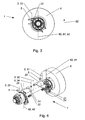
- the position of at least one of the engagement points 3 is substantially parallel to a vertical 82 of the vehicle trailer changeable, as in the in Fig. 5 to 7 illustrated second embodiment of the steered axle 1 is provided.
- the vertical 82 of the vehicle trailer is normal to the longitudinal direction of the vehicle Vehicle Trailer arranged with the vertical 82 of the vehicle trailer is arranged vertically when the vehicle trailer is on a horizontal plane.
- the second embodiment of the steered axle 1 is in the Fig. 5 to 7 insofar shown schematically simplified, as that the connection of the points 3 of the first slave cylinder 21 and the connection of the points 3 of the second slave cylinder 22 with other components of the steered axle 1 by partially projecting the ends of the two slave cylinders 21, 22 in the other components of the steered Axis 1 is shown.
- the actual connection of the points of attack 3 with the other components of the steered axle 1 can thereby in particular according to the in Fig. 1, 2 and 4 be formed joint connections shown.
- a - not shown - fourth embodiment of the steered axle 1 can be provided that the position of at least one of the points 3 is substantially parallel to a vertical 82 of the vehicle trailer changeable and that the position of at least one of the points 3 substantially parallel to Longitudinal direction of the vehicle trailer is changeable.
- Lenkknickung when steering the towing vehicle, varying angle between a longitudinal direction of the towing vehicle, ie a towing vehicle longitudinal direction, and the vehicle trailer longitudinal direction 81 is referred to as Lenkknickung hereinafter.
- the steering bend When the train is traveling straight ahead, the steering bend is 0 °. If - in the arrangement of the towing vehicle and the vehicle trailer on a plane - the towing vehicle is normal to the trailer, the steering bend is 90 °. Due to the geometry of a mechanical actuation of the master cylinder may be the case that the variable volume in the master cylinder and the variable steering buckling between the towing vehicle and the vehicle trailer are non-linearly related.
- the first slave cylinder 21, which comprises the hollow cylinder 24 and the piston rod 25, is arranged such that the hollow cylinder 24 is adjacent is arranged to the first point of application 31, as provided in the second embodiment of the steered axle 1 and in the Fig. 5 to 7 is shown.
- the hollow cylinder 24 of the first slave cylinder 21 is arranged closer than the piston rod 25 of the first slave cylinder 21 to the respective wheel 6 adjacent to the first slave cylinder 21.
- the above-described nonlinearity of the relationship of the steering buckling and the control signal can be at least partially compensated, whereby the steering errors occurring due to the nonlinearities in the mechanical system can at least be significantly reduced, possibly substantially compensated.
- first slave cylinder 21 and the second slave cylinder 22, which also includes a hollow cylinder 24 and a piston rod 25, are formed such that the piston rod 25 of the first slave cylinder 21 and the piston rod 25 of the second slave cylinder 22 adjacent to each other, in particular directed substantially to each other, are arranged.
- cornering are thereby advantageously both on the wheel 6, which is in the curve further inside, so inside the curve is arranged, and on the wheel 6, which is in the curve further out, so outside the curve, possibly minimized steering errors minimized, in particular substantially compensated.
- the position of at least one of the points 3 is substantially parallel to a vertical of the vehicle trailer changeable
- the first slave cylinder 21 and the second slave cylinder 22, which also has a hollow cylinder 24 and a Piston rod 25 includes are formed such that the piston rod 25 of the first slave cylinder 21 and the piston rod 25 of the second slave cylinder 22 adjacent to each other, in particular substantially directed to each other, are arranged, as also in the Fig. 5 to 7 is shown and provided in the second embodiment of the steered axle 1.
- the advantage here is that the arrangement of the axes of action of the first slave cylinder 21 and the second slave cylinder 22 are three-dimensional predeterminable arrange, so that the steering behavior of the vehicle trailer - despite purely mechanical operation of the master cylinder, ie without the aid of a computer-aided steering error compensation - very accurately to the steering behavior of the towing vehicle can be adjusted.
- the advantage here is that the forced steering of the vehicle trailer consumes no electricity and works reliably in case of failure of the on-board power supply system.
- a further advantage is that the vehicle trailer can be designed cost-effectively, since without computer-aided steering error compensation, and can be used cost-effectively.
Landscapes
- Engineering & Computer Science (AREA)
- Chemical & Material Sciences (AREA)
- Combustion & Propulsion (AREA)
- Transportation (AREA)
- Mechanical Engineering (AREA)
- Power Steering Mechanism (AREA)
- Steering-Linkage Mechanisms And Four-Wheel Steering (AREA)
Priority Applications (1)
| Application Number | Priority Date | Filing Date | Title |
|---|---|---|---|
| PL10807311T PL2512902T3 (pl) | 2009-12-18 | 2010-12-13 | Przyczepa pojazdu z układem kierowania wymuszonego |
Applications Claiming Priority (2)
| Application Number | Priority Date | Filing Date | Title |
|---|---|---|---|
| AT0200909A AT508251B1 (de) | 2009-12-18 | 2009-12-18 | Fahrzeuganhänger mit einer zwangslenkung |
| PCT/AT2010/000476 WO2011072316A1 (de) | 2009-12-18 | 2010-12-13 | Fahrzeuganhänger mit einer zwangslenkung |
Publications (2)
| Publication Number | Publication Date |
|---|---|
| EP2512902A1 EP2512902A1 (de) | 2012-10-24 |
| EP2512902B1 true EP2512902B1 (de) | 2014-02-26 |
Family
ID=43302220
Family Applications (1)
| Application Number | Title | Priority Date | Filing Date |
|---|---|---|---|
| EP10807311.5A Not-in-force EP2512902B1 (de) | 2009-12-18 | 2010-12-13 | Fahrzeuganhänger mit einer zwangslenkung |
Country Status (4)
| Country | Link |
|---|---|
| EP (1) | EP2512902B1 (pl) |
| AT (1) | AT508251B1 (pl) |
| PL (1) | PL2512902T3 (pl) |
| WO (1) | WO2011072316A1 (pl) |
Families Citing this family (1)
| Publication number | Priority date | Publication date | Assignee | Title |
|---|---|---|---|---|
| AT511942B1 (de) | 2011-09-16 | 2013-04-15 | Josef Ing Scharmueller | Lenkachse |
Family Cites Families (3)
| Publication number | Priority date | Publication date | Assignee | Title |
|---|---|---|---|---|
| DE202004000605U1 (de) * | 2004-01-15 | 2004-04-01 | Zunhammer, Sebastian, Dipl.-Ing. (FH) | Fahrzeuganhänger |
| ITTO20060287A1 (it) * | 2006-04-18 | 2007-10-19 | Cometto Ind | Rimorchio a lunghezza variabile per motrici gommate |
| DE102007056361B3 (de) * | 2007-11-22 | 2009-06-25 | Hydac System Gmbh | Hydraulisches Lenksystem für Fahrzeuganhänger |
-
2009
- 2009-12-18 AT AT0200909A patent/AT508251B1/de not_active IP Right Cessation
-
2010
- 2010-12-13 PL PL10807311T patent/PL2512902T3/pl unknown
- 2010-12-13 EP EP10807311.5A patent/EP2512902B1/de not_active Not-in-force
- 2010-12-13 WO PCT/AT2010/000476 patent/WO2011072316A1/de not_active Ceased
Also Published As
| Publication number | Publication date |
|---|---|
| PL2512902T3 (pl) | 2014-07-31 |
| AT508251B1 (de) | 2010-12-15 |
| WO2011072316A1 (de) | 2011-06-23 |
| AT508251A4 (de) | 2010-12-15 |
| EP2512902A1 (de) | 2012-10-24 |
Similar Documents
| Publication | Publication Date | Title |
|---|---|---|
| EP2801665B1 (de) | Straßenfräsmaschine zum Bearbeiten von Strassen- oder Bodenoberflächen, sowie Verfahren zum Lenken einer Strassenfräsmaschine | |
| EP2801664B1 (de) | Straßenfräsmaschine zum Bearbeiten von Straßen- oder Bodenoberflächen | |
| WO2018210587A1 (de) | Radaufhängung für ein zumindest geringfügig aktiv lenkbares hinterrad eines zweispurigen fahrzeugs, achse mit einer radaufhängung und fahrzeug mit einer radaufhängung | |
| DE3911885C2 (de) | Mehrachsfahrzeug | |
| EP2287024A1 (de) | Vorrichtung zur aktiven Spureinstellung | |
| EP3160828A1 (de) | Transportfahrzeug, insbesondere ein selbstangetriebenes transportfahrzeug, mit variabler breite | |
| DE102006028957A1 (de) | Hinterachslenkung für einen Fahrzeugkran | |
| EP1010608B1 (de) | Hydraulikanlage für die Dämpfung der Drehbewegung eines Drehgelenkes zwischen zwei Fahrzeugteilen eines Gelenkfahrzeuges, z. B. eines Gelenkbusses | |
| DE102014009036A1 (de) | Transportfahrzeug, insbesondere selbstangetriebenes Transportfahrzeug, mit variabler Breite | |
| DE102008031215B4 (de) | Spurhebel für ein Radfahreug mit Achsschenkellenkung und Verwendung des Spurhebels bei einem Fahrzeug | |
| EP2512902B1 (de) | Fahrzeuganhänger mit einer zwangslenkung | |
| DE202014005055U1 (de) | Transportfahrzeug, insbesondere selbstangetriebenes Transportfahrzeug, mit variabler Breite | |
| DE102007037765B4 (de) | Kraftfahrzeug umfassend lenkbare Vorder- und Hinterräder | |
| EP0518208B1 (de) | Vorrichtung zur Lenkungsumschaltung bei einem Fahrzeugkran | |
| EP2848108B1 (de) | Pflug | |
| DE202011108878U1 (de) | Hinterachslenkvorrichtung für Anhängefahrzeuge, insbesondere für Schneidwerkswagen | |
| EP4141171B1 (de) | Selbstfahrende baumaschine mit lenkantrieb | |
| EP2343229A2 (de) | Lenkachse | |
| DE3707700A1 (de) | Mehrachslenkanlage | |
| EP3290300B1 (de) | Mechanische lenkvorrichtung zur zwangslenkung von nutzfahrzeug-einzelradaufhängungen an sattelaufliegern abhängig vom relativgierwinkel zwischen zugfahrzeug und nachlauffahrzeug | |
| DE102019131298A1 (de) | Lenksystem mit einem elektromechanischen Lenkaktuator sowie Verfahren zum Ausstatten eines Fahrzeugs und Fahrzeug damit | |
| EP2755882B1 (de) | Lenkachse | |
| EP4190673B1 (de) | Fahrzeugachse und deren anordnung an einem fahrzeug | |
| EP0384105A1 (de) | Spurführungseinrichtung für gummibereifte Fahrzeuge | |
| DE10346299A1 (de) | Lenkeinrichtung für eine Tandemachse |
Legal Events
| Date | Code | Title | Description |
|---|---|---|---|
| PUAI | Public reference made under article 153(3) epc to a published international application that has entered the european phase |
Free format text: ORIGINAL CODE: 0009012 |
|
| 17P | Request for examination filed |
Effective date: 20120718 |
|
| AK | Designated contracting states |
Kind code of ref document: A1 Designated state(s): AL AT BE BG CH CY CZ DE DK EE ES FI FR GB GR HR HU IE IS IT LI LT LU LV MC MK MT NL NO PL PT RO RS SE SI SK SM TR |
|
| DAX | Request for extension of the european patent (deleted) | ||
| GRAP | Despatch of communication of intention to grant a patent |
Free format text: ORIGINAL CODE: EPIDOSNIGR1 |
|
| INTG | Intention to grant announced |
Effective date: 20131115 |
|
| GRAS | Grant fee paid |
Free format text: ORIGINAL CODE: EPIDOSNIGR3 |
|
| GRAA | (expected) grant |
Free format text: ORIGINAL CODE: 0009210 |
|
| AK | Designated contracting states |
Kind code of ref document: B1 Designated state(s): AL AT BE BG CH CY CZ DE DK EE ES FI FR GB GR HR HU IE IS IT LI LT LU LV MC MK MT NL NO PL PT RO RS SE SI SK SM TR |
|
| REG | Reference to a national code |
Ref country code: GB Ref legal event code: FG4D Free format text: NOT ENGLISH |
|
| REG | Reference to a national code |
Ref country code: CH Ref legal event code: EP |
|
| REG | Reference to a national code |
Ref country code: AT Ref legal event code: REF Ref document number: 653417 Country of ref document: AT Kind code of ref document: T Effective date: 20140315 |
|
| REG | Reference to a national code |
Ref country code: IE Ref legal event code: FG4D Free format text: LANGUAGE OF EP DOCUMENT: GERMAN |
|
| REG | Reference to a national code |
Ref country code: DE Ref legal event code: R096 Ref document number: 502010006216 Country of ref document: DE Effective date: 20140410 |
|
| REG | Reference to a national code |
Ref country code: NL Ref legal event code: T3 |
|
| REG | Reference to a national code |
Ref country code: LT Ref legal event code: MG4D |
|
| PG25 | Lapsed in a contracting state [announced via postgrant information from national office to epo] |
Ref country code: LT Free format text: LAPSE BECAUSE OF FAILURE TO SUBMIT A TRANSLATION OF THE DESCRIPTION OR TO PAY THE FEE WITHIN THE PRESCRIBED TIME-LIMIT Effective date: 20140226 Ref country code: NO Free format text: LAPSE BECAUSE OF FAILURE TO SUBMIT A TRANSLATION OF THE DESCRIPTION OR TO PAY THE FEE WITHIN THE PRESCRIBED TIME-LIMIT Effective date: 20140526 Ref country code: IS Free format text: LAPSE BECAUSE OF FAILURE TO SUBMIT A TRANSLATION OF THE DESCRIPTION OR TO PAY THE FEE WITHIN THE PRESCRIBED TIME-LIMIT Effective date: 20140626 |
|
| REG | Reference to a national code |
Ref country code: PL Ref legal event code: T3 |
|
| PG25 | Lapsed in a contracting state [announced via postgrant information from national office to epo] |
Ref country code: PT Free format text: LAPSE BECAUSE OF FAILURE TO SUBMIT A TRANSLATION OF THE DESCRIPTION OR TO PAY THE FEE WITHIN THE PRESCRIBED TIME-LIMIT Effective date: 20140626 Ref country code: CY Free format text: LAPSE BECAUSE OF FAILURE TO SUBMIT A TRANSLATION OF THE DESCRIPTION OR TO PAY THE FEE WITHIN THE PRESCRIBED TIME-LIMIT Effective date: 20140226 Ref country code: SE Free format text: LAPSE BECAUSE OF FAILURE TO SUBMIT A TRANSLATION OF THE DESCRIPTION OR TO PAY THE FEE WITHIN THE PRESCRIBED TIME-LIMIT Effective date: 20140226 Ref country code: FI Free format text: LAPSE BECAUSE OF FAILURE TO SUBMIT A TRANSLATION OF THE DESCRIPTION OR TO PAY THE FEE WITHIN THE PRESCRIBED TIME-LIMIT Effective date: 20140226 |
|
| PG25 | Lapsed in a contracting state [announced via postgrant information from national office to epo] |
Ref country code: HR Free format text: LAPSE BECAUSE OF FAILURE TO SUBMIT A TRANSLATION OF THE DESCRIPTION OR TO PAY THE FEE WITHIN THE PRESCRIBED TIME-LIMIT Effective date: 20140226 Ref country code: LV Free format text: LAPSE BECAUSE OF FAILURE TO SUBMIT A TRANSLATION OF THE DESCRIPTION OR TO PAY THE FEE WITHIN THE PRESCRIBED TIME-LIMIT Effective date: 20140226 |
|
| PG25 | Lapsed in a contracting state [announced via postgrant information from national office to epo] |
Ref country code: RO Free format text: LAPSE BECAUSE OF FAILURE TO SUBMIT A TRANSLATION OF THE DESCRIPTION OR TO PAY THE FEE WITHIN THE PRESCRIBED TIME-LIMIT Effective date: 20140226 Ref country code: EE Free format text: LAPSE BECAUSE OF FAILURE TO SUBMIT A TRANSLATION OF THE DESCRIPTION OR TO PAY THE FEE WITHIN THE PRESCRIBED TIME-LIMIT Effective date: 20140226 Ref country code: CZ Free format text: LAPSE BECAUSE OF FAILURE TO SUBMIT A TRANSLATION OF THE DESCRIPTION OR TO PAY THE FEE WITHIN THE PRESCRIBED TIME-LIMIT Effective date: 20140226 Ref country code: DK Free format text: LAPSE BECAUSE OF FAILURE TO SUBMIT A TRANSLATION OF THE DESCRIPTION OR TO PAY THE FEE WITHIN THE PRESCRIBED TIME-LIMIT Effective date: 20140226 |
|
| REG | Reference to a national code |
Ref country code: DE Ref legal event code: R097 Ref document number: 502010006216 Country of ref document: DE |
|
| PG25 | Lapsed in a contracting state [announced via postgrant information from national office to epo] |
Ref country code: ES Free format text: LAPSE BECAUSE OF FAILURE TO SUBMIT A TRANSLATION OF THE DESCRIPTION OR TO PAY THE FEE WITHIN THE PRESCRIBED TIME-LIMIT Effective date: 20140226 Ref country code: SK Free format text: LAPSE BECAUSE OF FAILURE TO SUBMIT A TRANSLATION OF THE DESCRIPTION OR TO PAY THE FEE WITHIN THE PRESCRIBED TIME-LIMIT Effective date: 20140226 |
|
| PLBE | No opposition filed within time limit |
Free format text: ORIGINAL CODE: 0009261 |
|
| STAA | Information on the status of an ep patent application or granted ep patent |
Free format text: STATUS: NO OPPOSITION FILED WITHIN TIME LIMIT |
|
| 26N | No opposition filed |
Effective date: 20141127 |
|
| REG | Reference to a national code |
Ref country code: DE Ref legal event code: R097 Ref document number: 502010006216 Country of ref document: DE Effective date: 20141127 |
|
| PG25 | Lapsed in a contracting state [announced via postgrant information from national office to epo] |
Ref country code: SI Free format text: LAPSE BECAUSE OF FAILURE TO SUBMIT A TRANSLATION OF THE DESCRIPTION OR TO PAY THE FEE WITHIN THE PRESCRIBED TIME-LIMIT Effective date: 20140226 |
|
| PG25 | Lapsed in a contracting state [announced via postgrant information from national office to epo] |
Ref country code: BE Free format text: LAPSE BECAUSE OF NON-PAYMENT OF DUE FEES Effective date: 20141231 |
|
| PG25 | Lapsed in a contracting state [announced via postgrant information from national office to epo] |
Ref country code: LU Free format text: LAPSE BECAUSE OF FAILURE TO SUBMIT A TRANSLATION OF THE DESCRIPTION OR TO PAY THE FEE WITHIN THE PRESCRIBED TIME-LIMIT Effective date: 20141213 |
|
| REG | Reference to a national code |
Ref country code: CH Ref legal event code: PL |
|
| GBPC | Gb: european patent ceased through non-payment of renewal fee |
Effective date: 20141213 |
|
| REG | Reference to a national code |
Ref country code: IE Ref legal event code: MM4A |
|
| REG | Reference to a national code |
Ref country code: FR Ref legal event code: ST Effective date: 20150831 |
|
| PG25 | Lapsed in a contracting state [announced via postgrant information from national office to epo] |
Ref country code: CH Free format text: LAPSE BECAUSE OF NON-PAYMENT OF DUE FEES Effective date: 20141231 Ref country code: GB Free format text: LAPSE BECAUSE OF NON-PAYMENT OF DUE FEES Effective date: 20141213 Ref country code: LI Free format text: LAPSE BECAUSE OF NON-PAYMENT OF DUE FEES Effective date: 20141231 Ref country code: IE Free format text: LAPSE BECAUSE OF NON-PAYMENT OF DUE FEES Effective date: 20141213 |
|
| PG25 | Lapsed in a contracting state [announced via postgrant information from national office to epo] |
Ref country code: FR Free format text: LAPSE BECAUSE OF NON-PAYMENT OF DUE FEES Effective date: 20141231 |
|
| PG25 | Lapsed in a contracting state [announced via postgrant information from national office to epo] |
Ref country code: SM Free format text: LAPSE BECAUSE OF FAILURE TO SUBMIT A TRANSLATION OF THE DESCRIPTION OR TO PAY THE FEE WITHIN THE PRESCRIBED TIME-LIMIT Effective date: 20140226 |
|
| PG25 | Lapsed in a contracting state [announced via postgrant information from national office to epo] |
Ref country code: MC Free format text: LAPSE BECAUSE OF FAILURE TO SUBMIT A TRANSLATION OF THE DESCRIPTION OR TO PAY THE FEE WITHIN THE PRESCRIBED TIME-LIMIT Effective date: 20140226 |
|
| PG25 | Lapsed in a contracting state [announced via postgrant information from national office to epo] |
Ref country code: GR Free format text: LAPSE BECAUSE OF FAILURE TO SUBMIT A TRANSLATION OF THE DESCRIPTION OR TO PAY THE FEE WITHIN THE PRESCRIBED TIME-LIMIT Effective date: 20140527 Ref country code: RS Free format text: LAPSE BECAUSE OF FAILURE TO SUBMIT A TRANSLATION OF THE DESCRIPTION OR TO PAY THE FEE WITHIN THE PRESCRIBED TIME-LIMIT Effective date: 20140226 Ref country code: BG Free format text: LAPSE BECAUSE OF FAILURE TO SUBMIT A TRANSLATION OF THE DESCRIPTION OR TO PAY THE FEE WITHIN THE PRESCRIBED TIME-LIMIT Effective date: 20140226 |
|
| PG25 | Lapsed in a contracting state [announced via postgrant information from national office to epo] |
Ref country code: TR Free format text: LAPSE BECAUSE OF FAILURE TO SUBMIT A TRANSLATION OF THE DESCRIPTION OR TO PAY THE FEE WITHIN THE PRESCRIBED TIME-LIMIT Effective date: 20140226 Ref country code: HU Free format text: LAPSE BECAUSE OF FAILURE TO SUBMIT A TRANSLATION OF THE DESCRIPTION OR TO PAY THE FEE WITHIN THE PRESCRIBED TIME-LIMIT; INVALID AB INITIO Effective date: 20101213 Ref country code: MT Free format text: LAPSE BECAUSE OF FAILURE TO SUBMIT A TRANSLATION OF THE DESCRIPTION OR TO PAY THE FEE WITHIN THE PRESCRIBED TIME-LIMIT Effective date: 20140226 |
|
| REG | Reference to a national code |
Ref country code: AT Ref legal event code: MM01 Ref document number: 653417 Country of ref document: AT Kind code of ref document: T Effective date: 20151213 |
|
| PG25 | Lapsed in a contracting state [announced via postgrant information from national office to epo] |
Ref country code: AT Free format text: LAPSE BECAUSE OF NON-PAYMENT OF DUE FEES Effective date: 20151213 |
|
| PGFP | Annual fee paid to national office [announced via postgrant information from national office to epo] |
Ref country code: PL Payment date: 20171204 Year of fee payment: 8 |
|
| PG25 | Lapsed in a contracting state [announced via postgrant information from national office to epo] |
Ref country code: MK Free format text: LAPSE BECAUSE OF FAILURE TO SUBMIT A TRANSLATION OF THE DESCRIPTION OR TO PAY THE FEE WITHIN THE PRESCRIBED TIME-LIMIT Effective date: 20140226 |
|
| PG25 | Lapsed in a contracting state [announced via postgrant information from national office to epo] |
Ref country code: AL Free format text: LAPSE BECAUSE OF FAILURE TO SUBMIT A TRANSLATION OF THE DESCRIPTION OR TO PAY THE FEE WITHIN THE PRESCRIBED TIME-LIMIT Effective date: 20140226 |
|
| PGFP | Annual fee paid to national office [announced via postgrant information from national office to epo] |
Ref country code: NL Payment date: 20181217 Year of fee payment: 9 |
|
| PGFP | Annual fee paid to national office [announced via postgrant information from national office to epo] |
Ref country code: IT Payment date: 20181218 Year of fee payment: 9 |
|
| PGFP | Annual fee paid to national office [announced via postgrant information from national office to epo] |
Ref country code: DE Payment date: 20181220 Year of fee payment: 9 |
|
| REG | Reference to a national code |
Ref country code: DE Ref legal event code: R119 Ref document number: 502010006216 Country of ref document: DE |
|
| REG | Reference to a national code |
Ref country code: NL Ref legal event code: MM Effective date: 20200101 |
|
| PG25 | Lapsed in a contracting state [announced via postgrant information from national office to epo] |
Ref country code: PL Free format text: LAPSE BECAUSE OF NON-PAYMENT OF DUE FEES Effective date: 20181213 |
|
| PG25 | Lapsed in a contracting state [announced via postgrant information from national office to epo] |
Ref country code: NL Free format text: LAPSE BECAUSE OF NON-PAYMENT OF DUE FEES Effective date: 20200101 |
|
| PG25 | Lapsed in a contracting state [announced via postgrant information from national office to epo] |
Ref country code: IT Free format text: LAPSE BECAUSE OF NON-PAYMENT OF DUE FEES Effective date: 20191213 Ref country code: DE Free format text: LAPSE BECAUSE OF NON-PAYMENT OF DUE FEES Effective date: 20200701 |