EP2512355B1 - Low-profile one-way valve - Google Patents
Low-profile one-way valve Download PDFInfo
- Publication number
- EP2512355B1 EP2512355B1 EP10795547.8A EP10795547A EP2512355B1 EP 2512355 B1 EP2512355 B1 EP 2512355B1 EP 10795547 A EP10795547 A EP 10795547A EP 2512355 B1 EP2512355 B1 EP 2512355B1
- Authority
- EP
- European Patent Office
- Prior art keywords
- segment
- lumen
- configuration
- balloon catheter
- valve
- Prior art date
- Legal status (The legal status is an assumption and is not a legal conclusion. Google has not performed a legal analysis and makes no representation as to the accuracy of the status listed.)
- Active
Links
- 239000012530 fluid Substances 0.000 claims description 27
- 238000004891 communication Methods 0.000 claims description 11
- 239000000463 material Substances 0.000 claims description 11
- 230000005489 elastic deformation Effects 0.000 claims description 5
- 229920000126 latex Polymers 0.000 claims description 3
- 229920000058 polyacrylate Polymers 0.000 claims description 2
- 229920002635 polyurethane Polymers 0.000 claims description 2
- 239000004814 polyurethane Substances 0.000 claims description 2
- 229920002379 silicone rubber Polymers 0.000 claims description 2
- 229920002725 thermoplastic elastomer Polymers 0.000 claims description 2
- 238000000034 method Methods 0.000 description 23
- 210000001953 common bile duct Anatomy 0.000 description 8
- 210000001519 tissue Anatomy 0.000 description 6
- 230000006835 compression Effects 0.000 description 5
- 238000007906 compression Methods 0.000 description 5
- 238000001356 surgical procedure Methods 0.000 description 5
- 239000000835 fiber Substances 0.000 description 4
- 238000011084 recovery Methods 0.000 description 4
- 210000001198 duodenum Anatomy 0.000 description 3
- 230000002440 hepatic effect Effects 0.000 description 3
- 229920000642 polymer Polymers 0.000 description 3
- 230000002980 postoperative effect Effects 0.000 description 3
- 239000007787 solid Substances 0.000 description 3
- 230000001225 therapeutic effect Effects 0.000 description 3
- 238000004873 anchoring Methods 0.000 description 2
- 210000000013 bile duct Anatomy 0.000 description 2
- 238000001574 biopsy Methods 0.000 description 2
- 230000006378 damage Effects 0.000 description 2
- 230000007423 decrease Effects 0.000 description 2
- 238000002695 general anesthesia Methods 0.000 description 2
- 238000001746 injection moulding Methods 0.000 description 2
- 208000014674 injury Diseases 0.000 description 2
- 238000002324 minimally invasive surgery Methods 0.000 description 2
- 230000036407 pain Effects 0.000 description 2
- 210000000277 pancreatic duct Anatomy 0.000 description 2
- 230000007170 pathology Effects 0.000 description 2
- 210000005070 sphincter Anatomy 0.000 description 2
- 230000008733 trauma Effects 0.000 description 2
- 239000000654 additive Substances 0.000 description 1
- 230000000996 additive effect Effects 0.000 description 1
- 239000000853 adhesive Substances 0.000 description 1
- 230000001070 adhesive effect Effects 0.000 description 1
- 210000004141 ampulla of vater Anatomy 0.000 description 1
- 210000003484 anatomy Anatomy 0.000 description 1
- 239000000560 biocompatible material Substances 0.000 description 1
- 230000015556 catabolic process Effects 0.000 description 1
- 210000003459 common hepatic duct Anatomy 0.000 description 1
- 238000007796 conventional method Methods 0.000 description 1
- 238000001816 cooling Methods 0.000 description 1
- 238000006731 degradation reaction Methods 0.000 description 1
- 230000002638 denervation Effects 0.000 description 1
- 230000001419 dependent effect Effects 0.000 description 1
- 230000007560 devascularization Effects 0.000 description 1
- 238000011161 development Methods 0.000 description 1
- 238000011846 endoscopic investigation Methods 0.000 description 1
- 238000001839 endoscopy Methods 0.000 description 1
- 238000005516 engineering process Methods 0.000 description 1
- 210000003238 esophagus Anatomy 0.000 description 1
- 230000002496 gastric effect Effects 0.000 description 1
- 238000003384 imaging method Methods 0.000 description 1
- 239000004816 latex Substances 0.000 description 1
- 238000002690 local anesthesia Methods 0.000 description 1
- 239000002184 metal Substances 0.000 description 1
- 210000003205 muscle Anatomy 0.000 description 1
- 238000002355 open surgical procedure Methods 0.000 description 1
- 230000002035 prolonged effect Effects 0.000 description 1
- 230000037390 scarring Effects 0.000 description 1
- 238000007789 sealing Methods 0.000 description 1
- 210000004514 sphincter of oddi Anatomy 0.000 description 1
- 238000007464 sphincterotomy Methods 0.000 description 1
- 210000002784 stomach Anatomy 0.000 description 1
- 238000012360 testing method Methods 0.000 description 1
Images


Classifications
-
- A—HUMAN NECESSITIES
- A61—MEDICAL OR VETERINARY SCIENCE; HYGIENE
- A61B—DIAGNOSIS; SURGERY; IDENTIFICATION
- A61B1/00—Instruments for performing medical examinations of the interior of cavities or tubes of the body by visual or photographical inspection, e.g. endoscopes; Illuminating arrangements therefor
- A61B1/00064—Constructional details of the endoscope body
- A61B1/00071—Insertion part of the endoscope body
- A61B1/0008—Insertion part of the endoscope body characterised by distal tip features
- A61B1/00082—Balloons
-
- A—HUMAN NECESSITIES
- A61—MEDICAL OR VETERINARY SCIENCE; HYGIENE
- A61M—DEVICES FOR INTRODUCING MEDIA INTO, OR ONTO, THE BODY; DEVICES FOR TRANSDUCING BODY MEDIA OR FOR TAKING MEDIA FROM THE BODY; DEVICES FOR PRODUCING OR ENDING SLEEP OR STUPOR
- A61M25/00—Catheters; Hollow probes
- A61M25/10—Balloon catheters
- A61M25/1018—Balloon inflating or inflation-control devices
-
- A—HUMAN NECESSITIES
- A61—MEDICAL OR VETERINARY SCIENCE; HYGIENE
- A61M—DEVICES FOR INTRODUCING MEDIA INTO, OR ONTO, THE BODY; DEVICES FOR TRANSDUCING BODY MEDIA OR FOR TAKING MEDIA FROM THE BODY; DEVICES FOR PRODUCING OR ENDING SLEEP OR STUPOR
- A61M39/00—Tubes, tube connectors, tube couplings, valves, access sites or the like, specially adapted for medical use
- A61M39/22—Valves or arrangement of valves
- A61M39/24—Check- or non-return valves
-
- A—HUMAN NECESSITIES
- A61—MEDICAL OR VETERINARY SCIENCE; HYGIENE
- A61B—DIAGNOSIS; SURGERY; IDENTIFICATION
- A61B17/00—Surgical instruments, devices or methods, e.g. tourniquets
- A61B17/34—Trocars; Puncturing needles
- A61B17/3417—Details of tips or shafts, e.g. grooves, expandable, bendable; Multiple coaxial sliding cannulas, e.g. for dilating
- A61B17/3421—Cannulas
- A61B17/3439—Cannulas with means for changing the inner diameter of the cannula, e.g. expandable
- A61B2017/3441—Cannulas with means for changing the inner diameter of the cannula, e.g. expandable with distal sealing means
-
- A—HUMAN NECESSITIES
- A61—MEDICAL OR VETERINARY SCIENCE; HYGIENE
- A61M—DEVICES FOR INTRODUCING MEDIA INTO, OR ONTO, THE BODY; DEVICES FOR TRANSDUCING BODY MEDIA OR FOR TAKING MEDIA FROM THE BODY; DEVICES FOR PRODUCING OR ENDING SLEEP OR STUPOR
- A61M39/00—Tubes, tube connectors, tube couplings, valves, access sites or the like, specially adapted for medical use
- A61M39/22—Valves or arrangement of valves
- A61M39/24—Check- or non-return valves
- A61M2039/2426—Slit valve
-
- A—HUMAN NECESSITIES
- A61—MEDICAL OR VETERINARY SCIENCE; HYGIENE
- A61M—DEVICES FOR INTRODUCING MEDIA INTO, OR ONTO, THE BODY; DEVICES FOR TRANSDUCING BODY MEDIA OR FOR TAKING MEDIA FROM THE BODY; DEVICES FOR PRODUCING OR ENDING SLEEP OR STUPOR
- A61M39/00—Tubes, tube connectors, tube couplings, valves, access sites or the like, specially adapted for medical use
- A61M39/22—Valves or arrangement of valves
- A61M39/24—Check- or non-return valves
- A61M2039/2433—Valve comprising a resilient or deformable element, e.g. flap valve, deformable disc
Definitions
- the present disclosure relates generally to medical devices, and more particularly to a low-profile one-way valve configured for use with a medical device.
- Minimally invasive alternatives such as endoscopic techniques, reduce pain, post-operative recovery time, and the destruction of healthy tissue.
- minimally invasive surgery the site of pathology is accessed through portals rather than through a significant incision, thus preserving the integrity of intervening tissues.
- These minimally invasive techniques also often require only local anesthesia. The avoidance of general anesthesia can reduce post-operative recovery time and the risk of complications.
- Peroral cholangioscopy is usually performed by two experienced endoscopists using a "mother-baby" scope system, in which a thin fiberscope is inserted into the working channel of a large therapeutic endoscope (e.g., a duodenoscope).
- the mother-baby scope technique can be expensive with regard to personnel and equipment: two endoscopists plus assistants, two image processors (one for each camera), and expensive fiber optics in the baby scope that can often be damaged during standard manipulation with resulting image degradation.
- the standard 1.2 mm working channel of fiber optic baby scopes limits diagnostic and therapeutic options. It is therefore desirable to provide an endoscope configured to function as a cholangioscope by being dimensioned to be navigable through hepatic and pancreatic ducts.
- Such scopes are currently available, but they encounter problems of efficient introduction to a patient's biliary duct in a procedure that provides high quality images (e.g., superior to fiber optics imaging) at a desirable procedure cost. These problems include the difficulty of navigating a larger fiber optic baby scope having a greater than 1.2 mm working channel through a mother scope and into a patient's biliary duct.
- Direct POC requires only a single endoscopist working with a single image processor, using a CMOS or CCD camera system that provides a 2 mm accessory channel, and that can be used with existing scopes, image processors, and monitors.
- Overtube-balloon-assisted direct peroral cholangioscopy by using an ultra-slim upper endoscope (Choi et al., Gastrointestinal Endoscopy, 69(4):935-40, April 2009 ), where an over-tube with a balloon of the type used for double-balloon enteroscopy was directed into the duodenum adjacent the Ampulla of Vater with an ultra-slim scope supported in the lumen of the over-tube, whereafter the scope was directed into the previously-dilated bile duct.
- Prior art US4795426 upon which the preamble of claim 1 is based, discloses a catheter placement cannula having a passage there-through to receive a catheter, made up of a substantially tubular body portion and a tip portion made of pliable material.
- the present disclosure generally provides a valve configured for a lumen of a medical device.
- the valve may be placed in a proximal end of an inflation lumen and used to seal the lumen, and allow introduction or release of fluid or gas as desired.
- the valve may be used, for example, with a balloon catheter in an endoscopic procedure to facilitate an exchange of endoscopes over the catheter shaft.
- the valve includes a valve body having a first segment and a second segment.
- the second segment is elastically deformable from a first configuration to a second configuration.
- the first segment is integral with the second segment.
- a lumen extends through the valve body.
- the lumen includes a first portion extending through the first segment and a second portion extending through the second segment.
- the second portion is actuable between an open configuration and a closed configuration. Elastic deformation of the second segment from the first configuration to the second configuration causes the second portion to actuate from the closed configuration to the open configuration.
- the valve in another embodiment, includes an elastically deformable body extending from a proximal end to a distal end along a longitudinal axis.
- a slit extends through the body from the proximal end to the distal end along the longitudinal axis.
- the body includes a first radial axis corresponding to the slit. Compression of the body along the first radial axis may cause elastic deformation of the body and may cause the slit to open to provide a path of fluid communication through the body from the proximal end to the distal end.
- the valve may further comprise a seal portion proximal to and integral with the body.
- the seal portion includes a lumen extending longitudinally therethrough, and preferably is aligned with the slit such that a path of fluid communication exists through the body and the seal portion when the slit is open.
- the seal portion is configured to engage and form a fluid tight seal with an interior surface of an inflation lumen of an elongate medical device, such as a balloon catheter.
- a balloon catheter assembly in another aspect, includes a balloon catheter having a proximal end, a distal end, an inflation lumen extending from the proximal end to the distal end, and a balloon disposed on the distal end and in fluid communication with the inflation lumen.
- the balloon catheter assembly further includes a valve comprising a valve body having a collapsed lumen extending therethrough. The collapsed lumen can be opened by elastically deforming the valve body from a first configuration to a second configuration.
- the balloon catheter assembly further includes a detachable hub comprising a seal capable of elastically deforming the valve body.
- the valve further comprises a seal portion proximal to and integral with the valve body, the seal portion comprising a lumen extending therethrough, wherein the seal portion lumen and the collapsed lumen are aligned and wherein the seal portion is configured to engage and form a fluid tight seal with an interior surface of the inflation lumen of the balloon catheter.
- an exemplary method of exchanging devices over a balloon catheter includes advancing a first medical device to a target area.
- a balloon catheter is advanced through the first medical device to the target area.
- the balloon catheter includes a distally located balloon, an inflation lumen in fluid communication with the balloon, and a valve disposed in the inflation lumen.
- the valve includes a valve body having a first segment and a second segment, the second segment elastically deformable from a first configuration to a second configuration.
- the first segment is integral with the second segment.
- a valve lumen extends through the valve body.
- the valve lumen includes a first portion extending through the first segment and a second portion extending through the second segment. The second portion is actuable between an open configuration and a closed configuration.
- Elastic deformation of the second segment from the first configuration to the second configuration causes the second portion to actuate from the closed configuration to the open configuration.
- the method further includes anchoring the balloon catheter at the target area by opening the valve and introducing an inflation media through the valve lumen and the inflation lumen to the balloon, thereby inflating the balloon.
- the valve may then be closed.
- the valve may be opened and closed with use of a Tuohy-Borst seal.
- the first medical device is removed from the target area by advancing the first medical device in a proximal direction over the balloon catheter until the balloon catheter is no longer disposed through the first medical device.
- a second medical device may then be advanced over the balloon catheter to the target area.
- proximal refers to a direction that is generally toward a physician during a medical procedure.
- distal refers to a direction that is generally toward a target site within a patient's anatomy during a medical procedure.
- hub refers to the proximal end structure of a balloon catheter including a connection structure configured for effective connection to provide a path of fluid communication between a source of inflation fluid or gas, a catheter inflation lumen, and a balloon lumen, and includes manifold-style hubs that may have more complex or ancillary structures.
- Tiohy-Borst seal refers to the specific structure associated in the art with that name, as well as all equivalent simple seals configured for maintaining fluid-patency during introduction of a solid item through a seal.
- ultra-slim endoscope refers to an endoscope having an outer diameter of about 6.0 mm or less.
- frustum refers to the portion of a solid that lies between two parallel planes intersecting the solid.
- FIG. 1 depicts a perspective view of valve 100 in a closed configuration.
- the valve includes a valve body 101 having a proximal end 102, a distal end 104, and a lumen 120 extending from the proximal end to the distal end.
- the valve body includes a first segment 108 integral with a second segment 110.
- the second segment is elastically deformable from a first, relaxed configuration to a second, deformed configuration.
- Lumen 120 includes a first portion 122 extending through segment 108, and a second portion 124 extending through segment 110.
- the second portion has a closed configuration and an open configuration.
- segment 110 When valve 100 is in the closed configuration, segment 110 is in the first configuration and portion 124 is in a closed (i.e., collapsed) configuration.
- portion 124 opens to provide a path of fluid communication through lumen 120 from proximal end 102 to distal end 104.
- FIGS. 2-3 depict side and top longitudinal cross sectional views of valve 100, respectively, and FIG. 4 depicts an end view of the valve.
- segment 108 has a frustum shaped body
- segment 110 has an elliptic cylinder shaped body.
- segment 108 has a circular cross section at proximal end 102 that tapers to an elliptic shaped cross section moving toward segment 110.
- Segment 108 generally has a length l of about 1 mm to about 25 mm
- segment 110 generally has a length l' of about 0 mm to about 3 mm.
- valve body 101 generally has a length of about 1 mm to about 28 mm.
- Segment 108 has a circular cross section diameter d at proximal end 102, generally ranging from about 0.5 mm to about 3 mm.
- Segment 110 has an elliptic or oval shaped cross section, defined by a transverse diameter td and a conjugate diameter cd .
- the transverse diameter generally ranges from about 0.5 mm to about 3.5 mm, and the conjugate diameter generally ranges from about 0.25 mm to about 3.5 mm.
- segment 108 has an elliptic cross section with transverse and conjugate diameters the same or about the same as the respective transverse and conjugate diameters of segment 110.
- the length of lumen 120 is defined by the additive length of segments 108 and 110 (i.e., l + l' ).
- First portion 122 of lumen 120 may have a circular cross-section at proximal end 102 with a diameter d ' ranging from about 0.1 mm to about 2.5 mm.
- the diameter of first portion 122 decreases as the lumen narrows moving toward segment 110, as depicted in FIGS. 2-3 .
- Second portion 124 is generally flat (e.g., appears as a slit) when in the collapsed configuration, having a transverse length l " along transverse diameter td ranging from about 0.4 mm to about 3.4 mm. While particular dimensions have been described, the skilled artisan will appreciate that all dimensions provided herein are intended as examples only, and that the presently disclosed valve may be fabricated having different dimensions and shapes as appropriate for the intended application.
- FIG. 5 shows an end view of valve 100 in an open configuration where segment 110 is in the second configuration.
- Arrows 150 and 151 represent two opposing forces applied to the external surface of segment 110 along transverse diameter td .
- second portion 124 opens to provide a path of fluid communication through lumen 120 from proximal end 102 to distal end 104, such as depicted in FIG. 5 .
- the valve may be closed by allowing segment 110 to relax back to the first configuration.
- the valve can be configured for use with a balloon catheter.
- the valve may be fabricated with appropriate dimensions, and thereafter press fit or glued into the catheter lumen at the proximal end of the catheter shaft.
- the valve may be configured to be placed in the absolute proximal end of the catheter lumen, or alternatively, may be configured for placement in a location slightly distal from the proximal end.
- FIGS. 6-8 depict a transverse cross-sectional view of a catheter shaft 401 of a balloon catheter 400 wherein valve 100 is disposed within an inflation lumen 402.
- proximal end 102 is in intimate contact with the inner lumen surface 404, thereby forming a fluid tight seal therewith.
- FIG. 6 shows valve 100 in the closed configuration.
- FIG. 7 shows valve 100 in a partially open configuration, there being an external force applied to the external surface 406 of catheter shaft 401, causing reduction of the catheter outer and inner diameters, as well as segment 110 along transverse diameter td .
- FIG. 8 shows valve 100 in the open configuration, the external force applied to the external surface 406 having deformed segment 110 such that transverse diameter td and conjugate diameter cd are the same, or about the same.
- a fluid or gas may be introduced through lumen 120 in either a distal or proximal direction, as desired.
- a Tuohy-Borst seal may be used to apply the external force to elastically deform valve 100 from a closed configuration to an open configuration.
- a Tuohy-Borst seal may be tightened down on the catheter shaft external surface 406 until valve 100 is in a desired open configuration, such as depicted in FIG. 8 (Tuohy-Borst seal not shown).
- a fluid may be introduced through the valve in a distal direction even when the valve is closed.
- the shape of lumen 120 through first portion 122 is configured to allow sufficient fluid pressure to be applied through first portion 122 such that second portion 124 opens in response, allowing fluid introduction in a distal direction.
- fluid movement through second portion 124 is generally prevented or substantially impeded, particularly backflow therethrough (i.e., fluid movement in the proximal direction).
- valve 100 may be used with a balloon catheter having a detachable hub.
- Some balloon catheters have hubs that are fixedly and irremovably attached to the catheter shaft.
- the outer diameter and/or cross-sectional area of these hubs are such that they would not fit through an elongate surgical device such as, for example, a lumen of a large-bore catheter, polymer biliary stent, working/accessory channel of an endoscope or other minimally invasive image-capture device.
- an elongate surgical device such as, for example, a lumen of a large-bore catheter, polymer biliary stent, working/accessory channel of an endoscope or other minimally invasive image-capture device.
- valve 100 By using valve 100 in combination with a balloon catheter having a detachable hub, an elongate surgical device (e.g., duodenoscope, ultra-slim endoscope, other camera or image-capturing device, polymer stent, larger-bore catheter, etc.) may be passed over the entire length of the catheter shaft without impediment at the proximal end of the catheter, and without irreversibly removing the hub from the catheter shaft. Further, because valve 100 fits within the lumen of the balloon catheter, the valve attributes no additional outer diameter to the catheter shaft, and an endoscope or other device can be smoothly exchanged thereover.
- duodenoscope e.g., duodenoscope, ultra-slim endoscope, other camera or image-capturing device, polymer stent, larger-bore catheter, etc.
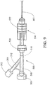
- FIG. 9 shows balloon catheter 400 having a removable hub, embodied as a manifold 500, releasably attached to catheter shaft 401.
- the manifold includes a Luer-type connector 502 on a side branch 504 and another connector 506 on a linear branch 508 that is substantially coaxial with the longitudinal axis of catheter shaft 401.
- Manifold 500 includes a main lumen 510 that is in fluid communication with a lumen 512 of the side branch 504.
- Manifold 500 may be releasably attached to the catheter shaft by a Tuohy-Borst seal 520, or some other type of fluid-tight compression seal.
- the portion of catheter shaft containing valve 100 within lumen 402 can be aligned with seal 520 such that the seal can be tightened around catheter shaft 401 to engage valve 100.
- the valve can be opened by compressing the catheter shaft with the Tuohy-Borst seal until the catheter inner lumen surface 404 engages segment 110, causing deformation thereof and opening of portion 124 of lumen 120, such as depicted in FIGS. 7-8 .
- manifold 500 may include a plurality of seals configured to engage the catheter shaft.
- the manifold may include a fluid-tight compression seal 530 including a sliding member 532 that enforces a compression fit when in the distal position shown, and that releases the catheter shaft when retracted proximally.
- the Tuohy-Borst seal 520 may be dedicated to opening and closing valve 100.
- the manifold may be attached to the catheter body with the compression tight seal 530, and valve 100 may be opened and closed as needed with the Tuohy-Borst seal 520.
- a proximal end 450 of the catheter shaft 401 is shown in the side view of FIG. 10A .
- the catheter shaft may include a stiffening wire 650 embedded in its wall some distance distal of the absolute proximal end, and preferably distal from the location along the shaft where valve 100 will reside in lumen 402.
- a cannula 655 may bridge the "wired" and "non-wired” catheter regions, with the cannula preferably distal the location along the shaft where valve 100 will reside in lumen 402.
- FIG. 10B shows a side view of the distal portion of balloon catheter 400.
- the balloon 604 is shown around the distal body portion of catheter shaft 401.
- a generally helical metal coil 605 may be disposed in the catheter in this distal portion to provide structural strength for navigating the catheter and to reinforce the catheter body in a region where one or more apertures (not shown) are included to provide a path of fluid communication from the catheter lumen 402 into the balloon lumen.
- the loop-tip 602 is attached to stiffening wire 650, and in the illustrated embodiment is sealed with the catheter shaft 401 by a general frustoconical adhesive or polymer structure that also seals the distal end of catheter inflation lumen 402.
- Loop-tip 602 preferably provides a generally atraumatic distal end that will facilitate navigation through body lumens and also permit monorail-style navigation along a wire guide.
- the valve may be used with a balloon catheter to facilitate a scope exchange during a cholangioscopy procedure.
- the valve may be disposed in lumen 402 at proximal end 450 of catheter shaft 401, as depicted in FIG. 10A .
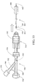
- catheter shaft 401 may be inserted into and secured with manifold 500 as depicted in FIG. 11 .
- the catheter shaft preferably is placed in the manifold such that Tuohy-Borst seal 520 aligns with valve 100, particularly segment 110.
- a side-viewing endoscope embodied as a duodenoscope 752 may be directed into the duodenum 750 of a patient adjacent the Amupulla of Vater about the Sphincter of Oddi 754, which is shown as having been cannulated (e.g., through a sphincterotomy).
- Loop-tipped catheter 400 extending through a working channel of duodenoscope 752 may then be directed through cannulated sphincter 754 into the common bile duct 756.
- FIG. 13 shows an exemplary method for introducing loop-tipped catheter 400 through the cannulated sphincter 754 into common bile duct 756 using a wire guide 758.
- wire guide 758 is first navigated into common bile duct 756. Then, loop 602 of catheter 400 is looped around wire guide 758 and directed in monorail fashion therealong into the common bile duct.
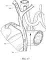
- catheter 400 may be directed further into the hepatic branch side (or the pancreatic duct side) of common bile duct 756. Then, as shown in FIG. 14 , balloon 604, which preferably will be a compliant balloon, may be inflated to anchor the distal end of the catheter in the hepatic branch 757. To inflate the balloon, with reference now to FIGS. 6-9 , Tuohy-Borst seal 520 may be operated to engage and compress catheter shaft 401 until inner lumen surface 404 engages valve 100 at segment 110, causing elastic deformation thereof and opening of the valve to allow fluid communication through lumen 120.
- balloon 604 which preferably will be a compliant balloon
- a selected inflation media may be introduced through the valve and thereafter through inflation lumen 402 to inflate balloon 604. It is preferable that balloon 604 be inflated sufficiently to anchor catheter 400, but that it does not significantly distend the ductal surface contacted by the inflated exterior balloon surface.
- Compliant balloons may be made of latex or other biocompatible material having desirable elasticity. In some embodiments, a balloon may be non-compliant in accords with desirable manipulation during a surgical procedure.
- FIG. 15 shows the proximal end of balloon catheter 400, with manifold 500 being detached therefrom.
- valve 100 Prior to detachment of manifold 500, valve 100 may be closed by disengaging Touhy-Borst seal 520, thereby sealing the proximal end of balloon catheter 400 to maintain fluid pressure in balloon 604.
- this removal of proximal manifold 500 allows a user to withdraw duodenoscope 752 over catheter shaft 401 while catheter 400 remains in place, anchored by the balloon (as shown in FIG. 14 ).
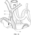
- an ultra-slim endoscope 760 is directed distally along catheter shaft 401.
- proximal catheter end 450 is inserted into the distal end of an accessory/working channel of ultra-slim scope 760.
- catheter shaft 401 may serve as a guide, allowing the distal end of ultra-slim scope 760 to be directed into common bile duct 756.
- balloon 604 may be deflated by opening valve 100 and allowing the inflation media to escape, with the option of providing negative pressure to withdraw the media using a syringe or vacuum source.
- Catheter 400 may then be withdrawn, freeing up the accessory channel of ultra-slim scope 760.
- a user may then introduce a diagnostic or therapeutic instrument through the accessory channel of ultra-slim scope 760 such as, for example, biopsy forceps 762 as shown in FIG. 19 .
- Valve 100 may be manufactured by conventional techniques as is known in the art.
- the valve may be manufactured by a primary process, such as injection molding.
- a secondary process may then be used to form portion 124 of lumen 120.
- the injection molding process includes filling a mold cavity with the selected material, applying heat and pressure, and cooling the manufactured article below its melt temperature upon release.
- Second portion 124 may be manufactured, for example, by cutting through segment 110 with a blade as appropriate to create a collapsed lumen (e.g., a slit) of desired dimensions.
- the valve preferably is constructed of an elastically deformable material.
- Suitable materials include, but are not limited to, silicone rubbers, latex rubbers, polyurethanes, acrylic polymers, thermoplastic elastomers, or any materials or combination of materials similar to these in structure and function, provided said material(s) will affect a suitable seal and will elastically deform in the circumstances described.
Landscapes
- Health & Medical Sciences (AREA)
- Life Sciences & Earth Sciences (AREA)
- Heart & Thoracic Surgery (AREA)
- Biomedical Technology (AREA)
- Animal Behavior & Ethology (AREA)
- General Health & Medical Sciences (AREA)
- Public Health (AREA)
- Veterinary Medicine (AREA)
- Engineering & Computer Science (AREA)
- Surgery (AREA)
- Biophysics (AREA)
- Pulmonology (AREA)
- Anesthesiology (AREA)
- Hematology (AREA)
- Medical Informatics (AREA)
- Molecular Biology (AREA)
- Physics & Mathematics (AREA)
- Radiology & Medical Imaging (AREA)
- Pathology (AREA)
- Optics & Photonics (AREA)
- Nuclear Medicine, Radiotherapy & Molecular Imaging (AREA)
- Child & Adolescent Psychology (AREA)
- Media Introduction/Drainage Providing Device (AREA)
- Endoscopes (AREA)
- Infusion, Injection, And Reservoir Apparatuses (AREA)
Applications Claiming Priority (2)
| Application Number | Priority Date | Filing Date | Title |
|---|---|---|---|
| US28666109P | 2009-12-15 | 2009-12-15 | |
| PCT/US2010/060097 WO2011081886A1 (en) | 2009-12-15 | 2010-12-13 | Low-profile one-way valve |
Publications (2)
| Publication Number | Publication Date |
|---|---|
| EP2512355A1 EP2512355A1 (en) | 2012-10-24 |
| EP2512355B1 true EP2512355B1 (en) | 2018-04-04 |
Family
ID=43867210
Family Applications (1)
| Application Number | Title | Priority Date | Filing Date |
|---|---|---|---|
| EP10795547.8A Active EP2512355B1 (en) | 2009-12-15 | 2010-12-13 | Low-profile one-way valve |
Country Status (7)
| Country | Link |
|---|---|
| US (1) | US9005164B2 (zh) |
| EP (1) | EP2512355B1 (zh) |
| JP (1) | JP5785951B2 (zh) |
| CN (1) | CN102753107B (zh) |
| AU (1) | AU2010337155C1 (zh) |
| CA (1) | CA2784444C (zh) |
| WO (1) | WO2011081886A1 (zh) |
Families Citing this family (8)
| Publication number | Priority date | Publication date | Assignee | Title |
|---|---|---|---|---|
| AU2012317947B2 (en) * | 2011-09-28 | 2015-06-11 | Terumo Kabushiki Kaisha | Catheter assembly |
| MX351948B (es) | 2012-04-06 | 2017-11-03 | Bard Inc C R | Válvula distal para un catéter. |
| DE102012109894A1 (de) * | 2012-04-10 | 2013-10-10 | Mtw - Endoskopie W. Haag Kg | Ballonkatheter und Verfahren zu dessen Verwendung |
| US10105085B2 (en) | 2012-11-03 | 2018-10-23 | ProVazo LLC | Directing hub used with vascular blood sampling catheter |
| JP2014138641A (ja) * | 2013-01-21 | 2014-07-31 | Fuji Systems Corp | スリット弁付きカテーテル |
| US9333077B2 (en) | 2013-03-12 | 2016-05-10 | Medtronic Vascular Galway Limited | Devices and methods for preparing a transcatheter heart valve system |
| KR101709769B1 (ko) * | 2014-04-18 | 2017-02-24 | 메디칸(주) | 밸브 및 이의 결합 방법 |
| USD933491S1 (en) * | 2018-12-06 | 2021-10-19 | Cooler Master Technology Inc. | Thermal paste syringe |
Family Cites Families (15)
| Publication number | Priority date | Publication date | Assignee | Title |
|---|---|---|---|---|
| US3477438A (en) * | 1967-04-17 | 1969-11-11 | Dwight L Allen | Catheter having one-way inflations valve |
| CA1009110A (en) * | 1971-04-30 | 1977-04-26 | Abbott Laboratories | Blood collecting assembly |
| US4038983A (en) * | 1976-01-26 | 1977-08-02 | Baxter Travenol Laboratories, Inc. | Fluid infusion pump |
| US4106497A (en) * | 1977-02-04 | 1978-08-15 | Becton, Dickinson And Company | Multiple sample needle assembly with indicator means |
| US4337770A (en) * | 1979-06-07 | 1982-07-06 | Young James E | Flow regulating device for arterial catheter systems |
| US4795426A (en) * | 1987-04-02 | 1989-01-03 | Solutech, Inc. | Catheter introducing device and method of placing catheter |
| US5167636A (en) * | 1991-10-24 | 1992-12-01 | Mectra Labs, Inc. | Cannula sealing mechanism |
| US5224933A (en) | 1992-03-23 | 1993-07-06 | C. R. Bard, Inc. | Catheter purge device |
| US5853397A (en) * | 1993-12-13 | 1998-12-29 | Migada, Inc. | Medical infusion apparatus including safety valve |
| US5643227A (en) * | 1995-01-19 | 1997-07-01 | Stevens; Robert C. | Hemostasis cannula valve apparatus and method of using same |
| US6595950B1 (en) * | 2000-05-11 | 2003-07-22 | Zevex, Inc. | Apparatus and method for preventing free flow in an infusion line |
| US8034035B2 (en) * | 2004-01-29 | 2011-10-11 | Navilyst Medical, Inc. | Pressure activated safety valve with high flow slit |
| JP2006087747A (ja) * | 2004-09-24 | 2006-04-06 | Sekisui Chem Co Ltd | 加圧・保圧治具及び医療用カテーテル |
| JP2006102222A (ja) | 2004-10-06 | 2006-04-20 | Sekisui Chem Co Ltd | 離脱型バルーンカテーテル |
| US20080172033A1 (en) * | 2007-01-16 | 2008-07-17 | Entellus Medical, Inc. | Apparatus and method for treatment of sinusitis |
-
2010
- 2010-12-13 CA CA2784444A patent/CA2784444C/en active Active
- 2010-12-13 AU AU2010337155A patent/AU2010337155C1/en active Active
- 2010-12-13 US US12/966,504 patent/US9005164B2/en active Active
- 2010-12-13 JP JP2012544685A patent/JP5785951B2/ja active Active
- 2010-12-13 CN CN201080063819.2A patent/CN102753107B/zh active Active
- 2010-12-13 WO PCT/US2010/060097 patent/WO2011081886A1/en active Application Filing
- 2010-12-13 EP EP10795547.8A patent/EP2512355B1/en active Active
Also Published As
| Publication number | Publication date |
|---|---|
| AU2010337155B2 (en) | 2014-07-03 |
| EP2512355A1 (en) | 2012-10-24 |
| JP2013513461A (ja) | 2013-04-22 |
| AU2010337155A1 (en) | 2012-07-12 |
| JP5785951B2 (ja) | 2015-09-30 |
| US9005164B2 (en) | 2015-04-14 |
| WO2011081886A1 (en) | 2011-07-07 |
| CA2784444A1 (en) | 2011-07-07 |
| AU2010337155C1 (en) | 2014-11-06 |
| CN102753107A (zh) | 2012-10-24 |
| US20110313354A1 (en) | 2011-12-22 |
| CA2784444C (en) | 2015-02-17 |
| CN102753107B (zh) | 2015-07-22 |
Similar Documents
| Publication | Publication Date | Title |
|---|---|---|
| EP2512355B1 (en) | Low-profile one-way valve | |
| US20110118546A1 (en) | Balloon catheter with detachable hub, and methods for same | |
| EP2512318B1 (en) | Endoscope sheath | |
| US20110172491A1 (en) | Detachable balloon catheter | |
| US7122003B2 (en) | Endoscopic retractor instrument and associated method | |
| US6918871B2 (en) | Method for accessing cavity | |
| US7824368B2 (en) | Method for endoscopic, transgastric access into the abdominal cavity | |
| US20120123463A1 (en) | Mechanically-guided transoral bougie | |
| KR101849489B1 (ko) | 극세경 내시경 보조 시스템 및 사용 방법 | |
| US20070287885A1 (en) | Endoscopic apparatus having an expandable balloon delivery system | |
| US20100057109A1 (en) | Endoscopic suturing device | |
| AU2007257793C1 (en) | Endoscopic apparatus having an expandable balloon delivery system | |
| US9844649B2 (en) | Telescopic wire guide | |
| US20220061866A1 (en) | Medical extraction assemblies and methods of using the same | |
| US20240008720A1 (en) | Elongate endoscopic covering |
Legal Events
| Date | Code | Title | Description |
|---|---|---|---|
| PUAI | Public reference made under article 153(3) epc to a published international application that has entered the european phase |
Free format text: ORIGINAL CODE: 0009012 |
|
| 17P | Request for examination filed |
Effective date: 20120710 |
|
| AK | Designated contracting states |
Kind code of ref document: A1 Designated state(s): AL AT BE BG CH CY CZ DE DK EE ES FI FR GB GR HR HU IE IS IT LI LT LU LV MC MK MT NL NO PL PT RO RS SE SI SK SM TR |
|
| DAX | Request for extension of the european patent (deleted) | ||
| 17Q | First examination report despatched |
Effective date: 20161021 |
|
| GRAP | Despatch of communication of intention to grant a patent |
Free format text: ORIGINAL CODE: EPIDOSNIGR1 |
|
| INTG | Intention to grant announced |
Effective date: 20171025 |
|
| RAP1 | Party data changed (applicant data changed or rights of an application transferred) |
Owner name: COOK MEDICAL TECHNOLOGIES LLC |
|
| RIN1 | Information on inventor provided before grant (corrected) |
Inventor name: HENNESSY, ERIC R. |
|
| GRAS | Grant fee paid |
Free format text: ORIGINAL CODE: EPIDOSNIGR3 |
|
| GRAA | (expected) grant |
Free format text: ORIGINAL CODE: 0009210 |
|
| AK | Designated contracting states |
Kind code of ref document: B1 Designated state(s): AL AT BE BG CH CY CZ DE DK EE ES FI FR GB GR HR HU IE IS IT LI LT LU LV MC MK MT NL NO PL PT RO RS SE SI SK SM TR |
|
| REG | Reference to a national code |
Ref country code: GB Ref legal event code: FG4D |
|
| REG | Reference to a national code |
Ref country code: CH Ref legal event code: EP |
|
| REG | Reference to a national code |
Ref country code: AT Ref legal event code: REF Ref document number: 984711 Country of ref document: AT Kind code of ref document: T Effective date: 20180415 |
|
| REG | Reference to a national code |
Ref country code: IE Ref legal event code: FG4D |
|
| REG | Reference to a national code |
Ref country code: DE Ref legal event code: R096 Ref document number: 602010049709 Country of ref document: DE |
|
| REG | Reference to a national code |
Ref country code: NL Ref legal event code: FP |
|
| REG | Reference to a national code |
Ref country code: LT Ref legal event code: MG4D |
|
| PG25 | Lapsed in a contracting state [announced via postgrant information from national office to epo] |
Ref country code: LT Free format text: LAPSE BECAUSE OF FAILURE TO SUBMIT A TRANSLATION OF THE DESCRIPTION OR TO PAY THE FEE WITHIN THE PRESCRIBED TIME-LIMIT Effective date: 20180404 Ref country code: PL Free format text: LAPSE BECAUSE OF FAILURE TO SUBMIT A TRANSLATION OF THE DESCRIPTION OR TO PAY THE FEE WITHIN THE PRESCRIBED TIME-LIMIT Effective date: 20180404 Ref country code: SE Free format text: LAPSE BECAUSE OF FAILURE TO SUBMIT A TRANSLATION OF THE DESCRIPTION OR TO PAY THE FEE WITHIN THE PRESCRIBED TIME-LIMIT Effective date: 20180404 Ref country code: NO Free format text: LAPSE BECAUSE OF FAILURE TO SUBMIT A TRANSLATION OF THE DESCRIPTION OR TO PAY THE FEE WITHIN THE PRESCRIBED TIME-LIMIT Effective date: 20180704 Ref country code: ES Free format text: LAPSE BECAUSE OF FAILURE TO SUBMIT A TRANSLATION OF THE DESCRIPTION OR TO PAY THE FEE WITHIN THE PRESCRIBED TIME-LIMIT Effective date: 20180404 Ref country code: AL Free format text: LAPSE BECAUSE OF FAILURE TO SUBMIT A TRANSLATION OF THE DESCRIPTION OR TO PAY THE FEE WITHIN THE PRESCRIBED TIME-LIMIT Effective date: 20180404 Ref country code: FI Free format text: LAPSE BECAUSE OF FAILURE TO SUBMIT A TRANSLATION OF THE DESCRIPTION OR TO PAY THE FEE WITHIN THE PRESCRIBED TIME-LIMIT Effective date: 20180404 Ref country code: BG Free format text: LAPSE BECAUSE OF FAILURE TO SUBMIT A TRANSLATION OF THE DESCRIPTION OR TO PAY THE FEE WITHIN THE PRESCRIBED TIME-LIMIT Effective date: 20180704 |
|
| PG25 | Lapsed in a contracting state [announced via postgrant information from national office to epo] |
Ref country code: RS Free format text: LAPSE BECAUSE OF FAILURE TO SUBMIT A TRANSLATION OF THE DESCRIPTION OR TO PAY THE FEE WITHIN THE PRESCRIBED TIME-LIMIT Effective date: 20180404 Ref country code: HR Free format text: LAPSE BECAUSE OF FAILURE TO SUBMIT A TRANSLATION OF THE DESCRIPTION OR TO PAY THE FEE WITHIN THE PRESCRIBED TIME-LIMIT Effective date: 20180404 Ref country code: GR Free format text: LAPSE BECAUSE OF FAILURE TO SUBMIT A TRANSLATION OF THE DESCRIPTION OR TO PAY THE FEE WITHIN THE PRESCRIBED TIME-LIMIT Effective date: 20180705 Ref country code: LV Free format text: LAPSE BECAUSE OF FAILURE TO SUBMIT A TRANSLATION OF THE DESCRIPTION OR TO PAY THE FEE WITHIN THE PRESCRIBED TIME-LIMIT Effective date: 20180404 |
|
| REG | Reference to a national code |
Ref country code: AT Ref legal event code: MK05 Ref document number: 984711 Country of ref document: AT Kind code of ref document: T Effective date: 20180404 |
|
| PG25 | Lapsed in a contracting state [announced via postgrant information from national office to epo] |
Ref country code: PT Free format text: LAPSE BECAUSE OF FAILURE TO SUBMIT A TRANSLATION OF THE DESCRIPTION OR TO PAY THE FEE WITHIN THE PRESCRIBED TIME-LIMIT Effective date: 20180806 |
|
| REG | Reference to a national code |
Ref country code: DE Ref legal event code: R097 Ref document number: 602010049709 Country of ref document: DE |
|
| PG25 | Lapsed in a contracting state [announced via postgrant information from national office to epo] |
Ref country code: AT Free format text: LAPSE BECAUSE OF FAILURE TO SUBMIT A TRANSLATION OF THE DESCRIPTION OR TO PAY THE FEE WITHIN THE PRESCRIBED TIME-LIMIT Effective date: 20180404 Ref country code: DK Free format text: LAPSE BECAUSE OF FAILURE TO SUBMIT A TRANSLATION OF THE DESCRIPTION OR TO PAY THE FEE WITHIN THE PRESCRIBED TIME-LIMIT Effective date: 20180404 Ref country code: SK Free format text: LAPSE BECAUSE OF FAILURE TO SUBMIT A TRANSLATION OF THE DESCRIPTION OR TO PAY THE FEE WITHIN THE PRESCRIBED TIME-LIMIT Effective date: 20180404 Ref country code: EE Free format text: LAPSE BECAUSE OF FAILURE TO SUBMIT A TRANSLATION OF THE DESCRIPTION OR TO PAY THE FEE WITHIN THE PRESCRIBED TIME-LIMIT Effective date: 20180404 Ref country code: CZ Free format text: LAPSE BECAUSE OF FAILURE TO SUBMIT A TRANSLATION OF THE DESCRIPTION OR TO PAY THE FEE WITHIN THE PRESCRIBED TIME-LIMIT Effective date: 20180404 Ref country code: RO Free format text: LAPSE BECAUSE OF FAILURE TO SUBMIT A TRANSLATION OF THE DESCRIPTION OR TO PAY THE FEE WITHIN THE PRESCRIBED TIME-LIMIT Effective date: 20180404 |
|
| PLBE | No opposition filed within time limit |
Free format text: ORIGINAL CODE: 0009261 |
|
| STAA | Information on the status of an ep patent application or granted ep patent |
Free format text: STATUS: NO OPPOSITION FILED WITHIN TIME LIMIT |
|
| PG25 | Lapsed in a contracting state [announced via postgrant information from national office to epo] |
Ref country code: SM Free format text: LAPSE BECAUSE OF FAILURE TO SUBMIT A TRANSLATION OF THE DESCRIPTION OR TO PAY THE FEE WITHIN THE PRESCRIBED TIME-LIMIT Effective date: 20180404 |
|
| 26N | No opposition filed |
Effective date: 20190107 |
|
| PG25 | Lapsed in a contracting state [announced via postgrant information from national office to epo] |
Ref country code: SI Free format text: LAPSE BECAUSE OF FAILURE TO SUBMIT A TRANSLATION OF THE DESCRIPTION OR TO PAY THE FEE WITHIN THE PRESCRIBED TIME-LIMIT Effective date: 20180404 |
|
| REG | Reference to a national code |
Ref country code: CH Ref legal event code: PL |
|
| PG25 | Lapsed in a contracting state [announced via postgrant information from national office to epo] |
Ref country code: MC Free format text: LAPSE BECAUSE OF FAILURE TO SUBMIT A TRANSLATION OF THE DESCRIPTION OR TO PAY THE FEE WITHIN THE PRESCRIBED TIME-LIMIT Effective date: 20180404 Ref country code: LU Free format text: LAPSE BECAUSE OF NON-PAYMENT OF DUE FEES Effective date: 20181213 |
|
| REG | Reference to a national code |
Ref country code: BE Ref legal event code: MM Effective date: 20181231 |
|
| PG25 | Lapsed in a contracting state [announced via postgrant information from national office to epo] |
Ref country code: FR Free format text: LAPSE BECAUSE OF NON-PAYMENT OF DUE FEES Effective date: 20181231 |
|
| PG25 | Lapsed in a contracting state [announced via postgrant information from national office to epo] |
Ref country code: BE Free format text: LAPSE BECAUSE OF NON-PAYMENT OF DUE FEES Effective date: 20181231 |
|
| PG25 | Lapsed in a contracting state [announced via postgrant information from national office to epo] |
Ref country code: LI Free format text: LAPSE BECAUSE OF NON-PAYMENT OF DUE FEES Effective date: 20181231 Ref country code: CH Free format text: LAPSE BECAUSE OF NON-PAYMENT OF DUE FEES Effective date: 20181231 |
|
| PG25 | Lapsed in a contracting state [announced via postgrant information from national office to epo] |
Ref country code: MT Free format text: LAPSE BECAUSE OF NON-PAYMENT OF DUE FEES Effective date: 20181213 |
|
| PG25 | Lapsed in a contracting state [announced via postgrant information from national office to epo] |
Ref country code: TR Free format text: LAPSE BECAUSE OF FAILURE TO SUBMIT A TRANSLATION OF THE DESCRIPTION OR TO PAY THE FEE WITHIN THE PRESCRIBED TIME-LIMIT Effective date: 20180404 |
|
| PG25 | Lapsed in a contracting state [announced via postgrant information from national office to epo] |
Ref country code: CY Free format text: LAPSE BECAUSE OF FAILURE TO SUBMIT A TRANSLATION OF THE DESCRIPTION OR TO PAY THE FEE WITHIN THE PRESCRIBED TIME-LIMIT Effective date: 20180404 Ref country code: MK Free format text: LAPSE BECAUSE OF NON-PAYMENT OF DUE FEES Effective date: 20180404 Ref country code: HU Free format text: LAPSE BECAUSE OF FAILURE TO SUBMIT A TRANSLATION OF THE DESCRIPTION OR TO PAY THE FEE WITHIN THE PRESCRIBED TIME-LIMIT; INVALID AB INITIO Effective date: 20101213 |
|
| PG25 | Lapsed in a contracting state [announced via postgrant information from national office to epo] |
Ref country code: IS Free format text: LAPSE BECAUSE OF FAILURE TO SUBMIT A TRANSLATION OF THE DESCRIPTION OR TO PAY THE FEE WITHIN THE PRESCRIBED TIME-LIMIT Effective date: 20180804 |
|
| P01 | Opt-out of the competence of the unified patent court (upc) registered |
Effective date: 20230602 |
|
| PGFP | Annual fee paid to national office [announced via postgrant information from national office to epo] |
Ref country code: NL Payment date: 20231110 Year of fee payment: 14 |
|
| PGFP | Annual fee paid to national office [announced via postgrant information from national office to epo] |
Ref country code: GB Payment date: 20231108 Year of fee payment: 14 |
|
| PGFP | Annual fee paid to national office [announced via postgrant information from national office to epo] |
Ref country code: IT Payment date: 20231215 Year of fee payment: 14 Ref country code: IE Payment date: 20231128 Year of fee payment: 14 Ref country code: DE Payment date: 20231108 Year of fee payment: 14 |