EP2512352B1 - Formspeichernde mehrfaservorrichtung - Google Patents
Formspeichernde mehrfaservorrichtung Download PDFInfo
- Publication number
- EP2512352B1 EP2512352B1 EP10842570.3A EP10842570A EP2512352B1 EP 2512352 B1 EP2512352 B1 EP 2512352B1 EP 10842570 A EP10842570 A EP 10842570A EP 2512352 B1 EP2512352 B1 EP 2512352B1
- Authority
- EP
- European Patent Office
- Prior art keywords
- members
- coiled
- elongate members
- coil
- shape memory
- Prior art date
- Legal status (The legal status is an assumption and is not a legal conclusion. Google has not performed a legal analysis and makes no representation as to the accuracy of the status listed.)
- Not-in-force
Links
Images

Classifications
-
- A—HUMAN NECESSITIES
- A61—MEDICAL OR VETERINARY SCIENCE; HYGIENE
- A61B—DIAGNOSIS; SURGERY; IDENTIFICATION
- A61B17/00—Surgical instruments, devices or methods, e.g. tourniquets
- A61B17/12—Surgical instruments, devices or methods, e.g. tourniquets for ligaturing or otherwise compressing tubular parts of the body, e.g. blood vessels, umbilical cord
- A61B17/12022—Occluding by internal devices, e.g. balloons or releasable wires
-
- A—HUMAN NECESSITIES
- A61—MEDICAL OR VETERINARY SCIENCE; HYGIENE
- A61M—DEVICES FOR INTRODUCING MEDIA INTO, OR ONTO, THE BODY; DEVICES FOR TRANSDUCING BODY MEDIA OR FOR TAKING MEDIA FROM THE BODY; DEVICES FOR PRODUCING OR ENDING SLEEP OR STUPOR
- A61M29/00—Dilators with or without means for introducing media, e.g. remedies
-
- A—HUMAN NECESSITIES
- A61—MEDICAL OR VETERINARY SCIENCE; HYGIENE
- A61B—DIAGNOSIS; SURGERY; IDENTIFICATION
- A61B17/00—Surgical instruments, devices or methods, e.g. tourniquets
- A61B17/12—Surgical instruments, devices or methods, e.g. tourniquets for ligaturing or otherwise compressing tubular parts of the body, e.g. blood vessels, umbilical cord
- A61B17/12022—Occluding by internal devices, e.g. balloons or releasable wires
- A61B17/12099—Occluding by internal devices, e.g. balloons or releasable wires characterised by the location of the occluder
- A61B17/12109—Occluding by internal devices, e.g. balloons or releasable wires characterised by the location of the occluder in a blood vessel
- A61B17/12113—Occluding by internal devices, e.g. balloons or releasable wires characterised by the location of the occluder in a blood vessel within an aneurysm
-
- A—HUMAN NECESSITIES
- A61—MEDICAL OR VETERINARY SCIENCE; HYGIENE
- A61B—DIAGNOSIS; SURGERY; IDENTIFICATION
- A61B17/00—Surgical instruments, devices or methods, e.g. tourniquets
- A61B17/12—Surgical instruments, devices or methods, e.g. tourniquets for ligaturing or otherwise compressing tubular parts of the body, e.g. blood vessels, umbilical cord
- A61B17/12022—Occluding by internal devices, e.g. balloons or releasable wires
- A61B17/12131—Occluding by internal devices, e.g. balloons or releasable wires characterised by the type of occluding device
- A61B17/12168—Occluding by internal devices, e.g. balloons or releasable wires characterised by the type of occluding device having a mesh structure
- A61B17/12172—Occluding by internal devices, e.g. balloons or releasable wires characterised by the type of occluding device having a mesh structure having a pre-set deployed three-dimensional shape
-
- A—HUMAN NECESSITIES
- A61—MEDICAL OR VETERINARY SCIENCE; HYGIENE
- A61L—METHODS OR APPARATUS FOR STERILISING MATERIALS OR OBJECTS IN GENERAL; DISINFECTION, STERILISATION OR DEODORISATION OF AIR; CHEMICAL ASPECTS OF BANDAGES, DRESSINGS, ABSORBENT PADS OR SURGICAL ARTICLES; MATERIALS FOR BANDAGES, DRESSINGS, ABSORBENT PADS OR SURGICAL ARTICLES
- A61L31/00—Materials for other surgical articles, e.g. stents, stent-grafts, shunts, surgical drapes, guide wires, materials for adhesion prevention, occluding devices, surgical gloves, tissue fixation devices
- A61L31/04—Macromolecular materials
-
- A—HUMAN NECESSITIES
- A61—MEDICAL OR VETERINARY SCIENCE; HYGIENE
- A61B—DIAGNOSIS; SURGERY; IDENTIFICATION
- A61B17/00—Surgical instruments, devices or methods, e.g. tourniquets
- A61B2017/00831—Material properties
- A61B2017/00867—Material properties shape memory effect
-
- A—HUMAN NECESSITIES
- A61—MEDICAL OR VETERINARY SCIENCE; HYGIENE
- A61B—DIAGNOSIS; SURGERY; IDENTIFICATION
- A61B17/00—Surgical instruments, devices or methods, e.g. tourniquets
- A61B2017/00831—Material properties
- A61B2017/00867—Material properties shape memory effect
- A61B2017/00871—Material properties shape memory effect polymeric
-
- A—HUMAN NECESSITIES
- A61—MEDICAL OR VETERINARY SCIENCE; HYGIENE
- A61B—DIAGNOSIS; SURGERY; IDENTIFICATION
- A61B17/00—Surgical instruments, devices or methods, e.g. tourniquets
- A61B17/12—Surgical instruments, devices or methods, e.g. tourniquets for ligaturing or otherwise compressing tubular parts of the body, e.g. blood vessels, umbilical cord
- A61B17/12022—Occluding by internal devices, e.g. balloons or releasable wires
- A61B2017/1205—Introduction devices
- A61B2017/12054—Details concerning the detachment of the occluding device from the introduction device
-
- A—HUMAN NECESSITIES
- A61—MEDICAL OR VETERINARY SCIENCE; HYGIENE
- A61L—METHODS OR APPARATUS FOR STERILISING MATERIALS OR OBJECTS IN GENERAL; DISINFECTION, STERILISATION OR DEODORISATION OF AIR; CHEMICAL ASPECTS OF BANDAGES, DRESSINGS, ABSORBENT PADS OR SURGICAL ARTICLES; MATERIALS FOR BANDAGES, DRESSINGS, ABSORBENT PADS OR SURGICAL ARTICLES
- A61L2400/00—Materials characterised by their function or physical properties
- A61L2400/16—Materials with shape-memory or superelastic properties
-
- C—CHEMISTRY; METALLURGY
- C08—ORGANIC MACROMOLECULAR COMPOUNDS; THEIR PREPARATION OR CHEMICAL WORKING-UP; COMPOSITIONS BASED THEREON
- C08L—COMPOSITIONS OF MACROMOLECULAR COMPOUNDS
- C08L2201/00—Properties
- C08L2201/12—Shape memory
Definitions
- the invention relates generally to implantable devices for interventional therapeutic treatment, and more particularly concerns an endoluminally delivered device for cerebral aneurysm isolation and repair.
- Interventional Neuroradiology is a medical discipline expanding minimally invasive treatments for intracranial vascular defects and vascular malformations while avoiding the cost and burden of open surgery.
- INR treatments include treating cerebral vascular malformations such as cerebral aneurysms, a bulging and weakening of the vessel wall; and arteriovenous malformations (AVMs) wherein the artery and vein are connected.
- Vasoocclusive (V-o) devices are typically used to isolate and/or fill the defect.
- Other INR procedures include occlusion of arteriovenous fistulae (AVF), parent vessel sacrifice (PVS), and tumor indications among other conditions.
- INR clinicians utilize various imaging modalities (primarily fluoroscopy) along with percutaneous (vascular access) guide and delivery catheters to routinely conduct, for example, vascular "stenting" to maintain patency of a diseased vessel lumen or provide support of at the neck of an aneurysm to retain a second device for aneurysm repair, and/or aneurysm embolization to isolate a vascular aneurysm's weakened vessel wall from blood flow and blood pressure.
- imaging modalities primarily fluoroscopy
- percutaneous (vascular access) guide and delivery catheters to routinely conduct, for example, vascular "stenting" to maintain patency of a diseased vessel lumen or provide support of at the neck of an aneurysm to retain a second device for aneurysm repair, and/or aneurysm embolization to isolate a vascular aneurysm's weakened vessel wall from blood flow and blood pressure.
- Cerebral aneurysms tend to occur in anterior and posterior communicating arteries, and a middle cerebral artery. The majority of these aneurysms are located at either curvature in the vessels or at bifurcations of these vessels. These defects can be detected prior to rupture through related symptoms (e.g., affected vision, headaches, etc). However, cerebral aneurysms are most often diagnosed by the rupture and subarachnoid bleeding within the brain, and in many instances, leading to debilitating stroke and/or death.
- cerebral aneurysms are commonly treated in open surgical procedures where the diseased vessel segment is clipped across the base of the aneurysm. While considered to be an effective surgical technique, particularly considering an alternative which may be a ruptured or re-bleed of a cerebral aneurysm, conventional neurosurgery suffers from a number of disadvantages.
- the procedure is highly invasive, requiring sawing through the bony cranium; it requires experienced surgeons and well- equipped surgical facilities; and surgical cerebral aneurysm repair has a relatively high mortality and morbidity rate of about 2% to 10%.
- patients are referred by the neurosurgeon to INR physicians for INR coiling or aneurysm isolation (both pre-ruptured and ruptured defects) when the site is inaccessible for surgical treatment or the neurosurgeon believes the aneurysm characteristics may be a good candidate for INR coiling.
- INR coiled patients have required retreatment due to a reoccurrence of the aneurysm believed to be caused by insufficient packing of the coil material in the aneurysm sack.
- the coils form a "coil pack" to isolate the weakened vessel wall from the primary vessel's blood flow and pressure.
- Voids in the coil pack developed either during the procedure or post operatively, cause channels for blood flow and pressure to reach the weakened vessel wall resulting in a continuation of the risky disease state and potential for aneurysm rupture.
- Successful isolation results in an endothelial cell to endothelial cell closure of the aneurysm and therefore a cure for the disease.
- v-o vaso-occlusive
- Packing factor is a measure of the aneurysm's sack volume displaced by the v-o device.
- higher packing factors measured during the procedure are associated by clinicians with a lower incidence of reoccurrence and need for retreatment.
- Low packing factors allow the paths for blood flow and pressure to become re-established and stress is again exerted on the weakened vessel wall.
- packing factors of 40% are considered very good with metal coils.
- Other devices, utilizing non-metal materials have attempted to increase the packing factor above this level with limited success.
- the v-o devices can take a variety of configurations, and are generally formed of one or more elements that are larger in the deployed configuration than when they are within the delivery catheter prior to placement.
- One widely used v-o device is a helical wire coil having a deployed configuration which may be dimensioned to engage the walls of the anatomical space, e.g., vessel.
- One anatomically shaped v-o device that forms itself into a shape of an anatomical cavity such as an aneurysm and is made of a pre-formed strand of flexible material that can be a nickel-titanium alloy is known. That v-o device comprises one or more members wound to form a generally spherical or ovoid shape in a relaxed state.
- the members can be a helically wound coil or a co-woven braid formed of a biocompatible material, and the device is sized and shaped to fit within a vascular cavity or vessel, such as for treatment of an aneurysm or a fistula.
- the v-o member can be first helically wound or braided in a generally linear fashion, then wound around an appropriately shaped mandrel or form, and heat treated to retain the shape after removal from the heating form.
- the primary shape is a coil of wire that is then formed into a more complex secondary shape.
- the primary coil comprises a wound resilient alloy wire formed as a straight coil, on which a bent secondary shape with coiled ends is imposed.
- metal embolic coils known including those with offset helical and twisted shapes having multiple axially offset longitudinal or focal axes with a secondary shape with coiled ends and a middle loop.
- a stretch-resistant v-o coil is also known that is formed from a helically wound primary coil and a stretch resistant member, that can also have a secondary shape with coiled ends and a middle loop, and an embolization coil having a single closed loop.
- Highly flexible coils with secondary shape are also known that form an occlusive implant that is sufficiently flexible that it can be damaged during handling and maintain that configuration.
- a wire wound platinum coil form is a common construction for catheter guidewires and has been adapted for occlusive coils
- significant IP effort has focused on key incremental features that define an acceptable product.
- Some metal coils are coated with a bioabsorbable polymer (PLGA, etc) as a means of enhancing blood/tissue interaction.
- Other coils are coated with a hydrogel to cause them to swell in-situ and provide a tighter coil pack.
- PLGA bioabsorbable polymer
- micro-coils formed of very small diameter wire may be used in order to restrict, reinforce, or to occlude such small diameters areas of the vasculature.
- a variety of materials have been suggested for use in such micro-coils, including nickel-titanium alloys, copper, stainless steel, platinum, tungsten, various plastics or the like, each of which offers certain benefits in various applications.
- nickel-titanium alloys copper, stainless steel, platinum, tungsten, various plastics or the like, each of which offers certain benefits in various applications.
- various materials are more or less kink resistant when nickel-titanium alloys are dimensioned into wire smaller than approximately 0.254 mm (0.010 inches) in diameter, they can have low yield strength and can kink more easily, thereby limiting the applications for such finely drawn wire in the fabrication of v-o devices.
- nickel-titanium alloys are not radiopaque in small diameters, and a single nickel-titanium wire may need to be approximately 0.305 mm (0.012 inches) in diameter to be somewhat radiopaque.
- a thickness of a single nickel-titanium wire would also be relatively stiff and possibly traumatic to the placement site, particularly if used for treatment of delicate and already damaged areas of the small diameter vasculature such as an aneurysm in an artery or vein in the brain.
- polymer coils have become available which provide a continuous single fiber that is delivered and trimmed to length.
- some polymer coils include specific limitations relying on delivery of a single fiber and require a specific catheter to achieve the cutting/trimming of the single fiber. Trimming/cutting during surgery may also increase procedure time and require a specialized tool to deliver and perform the procedure.
- traditional polymers that are not shape memory polymers cannot provide suitable "shape certainty" after storage in a constrained or stressed condition for extended periods.
- Traditional polymers suffer from "creep” resulting in a loss of shape memory when deployed from a constrained package.
- Traditional polymer devices do not exhibit shape certainty as a predictable, precise shape after deployment.
- current metal and polymer coils utilize resilient materials operating within simple elastic limits to maintain the unique coiled sample post deployment (if at all) while the device is being held in a straight configuration inside of a constrained package such as a coil holder (tube/hub device) that allows easy physician loading into the proximal end of the delivery catheter.
- a constrained package such as a coil holder (tube/hub device) that allows easy physician loading into the proximal end of the delivery catheter.
- an "aneurysm filler” is described as a single fiber that incorporates a “transport shape” and a “three dimensional shape which is manifest when the main body is deployed in an aneurysm.”
- the aneurysm filler material does not have a specific predetermined shape, nor does it present shape certainty of reproducing that predetermined shape upon delivery of the single fiber material into the aneurysm. In this way, the aneurysm filler single fiber material has the potential to come into sharp contact with the fragile diseased vessel wall of an aneurysm, increasing the potential for rupture or injury.
- Delivery of such a coil in the treatment of aneurysms or other types of arteriovenous malformations can be accomplished by a variety of means, including via a catheter in which a single device is pushed through the catheter by a pusher attached to the coil.
- the coil passes through the lumen of the catheter in a linear shape and takes on a complex shape as it was originally formed after being deployed into the area of interest, such as an aneurysm.
- Varieties of precision detachment mechanisms to release the single coil from a pusher have been developed and are known.
- the physician must sequentially reload the catheter with several individual coils until he/she has determined the occlusion is sufficient.
- the physician must sequentially reload the catheter with several individuals coils, experiencing some trepidation of getting the coil positioned and detached correctly each time.
- This physician typically determines whether sufficient coils have been deployed by assessing the level of occlusion of the vessel flow or by evaluating the density of the coil packed into the aneurysm sack (e.g., coil pack), both performed by using contrast media with typical medical imaging techniques.
- This "place and assess" method can extend the medical procedure time, cost and also can increase the imaging exposure (e.g., radiation exposure) to both the patient and the physician.
- WO0010469 (A1 ) discloses a vasoocclusive coil which has a primary coil configuration with a helical loop at least one end.
- the terminal helical loop can have a J-shaped configuration, preferably with a loop diameter of about 2 mm.
- the coil is preferably provided with helical loops at both ends, with helical loop at the proximal and distal ends of the coil acting as an anchor to prevent the coil from coming free from the location being treated and escaping into the vasculature.
- Some embodiments may include a permeable shell configured to occlude blood flow therethrough.
- WO2010115076 (A2 ) describes shape memory materials (SMM) which are formed as coil-shaped vascular occlusion devices upon deployment.
- SMP shape memory polymer
- SMP shape memory polymer
- Interconnecting structures are formed on ends of elongated members in the pre-deployment shape for multiple coil insertion capability within an introducer.
- Channels are formed in pre-deployment shape, elongate members that allow access for injection of imaging contrast agent or concurrent placement of instruments.
- a single SMM occlusive device transforms into multiple, smaller diameter coils in the deployed state to generate a complex occlusive structure.
- a SMM occlusive device has a collapsed fabric component attached to and extending along a sidewall during storage and insertion, and then deploys as a coil to form a single- or multiple-layer occlusive fabric surface within a center of the coil.
- EP2098174 discloses a system that includes a catheter including a distal portion for location at least partially in an aneurysm, the catheter including a proximal portion, the catheter to transport a biocompatible polymeric strand to an aneurysm, a biocompatible polymeric strand sized to slide through the catheter and a heated excise collar coupled to the distal portion of the catheter, the heated excise collar to provide radial heat from the catheter inward to melt and excise the biocompatible polymeric strand.
- the present teaching provides a shape memory coiling device as detailed in claim 1. Also provided is a method according to claim 7. Advantageous features are provided in the dependent claims.
- a shape memory coiling device for occluding a vascular target.
- the device may be formed of a shape memory polymer material.
- the shape memory material may be formed in a formation state as a plurality of coiled members and may have a specific shape and stiffness which is then constrained into a pre-deployed state as a plurality of elongate members configured for delivery through a delivery device wherein the plurality of elongate members are aligned axially with respect to each other and the delivery device.
- the shape memory material, in a pre-deployed state may also exhibit stiffness that enhances the ability to deliver the shape memory material through the delivery device.
- the shape memory material may be formed in an intra-deployed state such that at least one of the plurality of elongate members will anchor the device before filling the vascular target and becoming a coiled member.
- the shape memory material may be formed in an intra-deployed state such that all of the elongate members coil upon delivery through a delivery device to form a non-anchored coil pack that enlarges with the addition of more material coming into contact with the anatomical space upon delivery of sufficient material.
- the shape memory material may be formed in a deployed state as a plurality of coiled members.
- the vascular target is an aneurysm.
- the plurality of coiled members in the formation state is the same plurality of coiled members as in the deployed state.
- a shape memory coiling device for occluding a vascular target may be formed of a shape memory polymer material.
- the shape memory material may be formed in a pre-deployed state as a plurality of elongate members configured for delivery through a delivery device wherein the plurality of shape memory material elongate members are grouped or connected together at a midpoint of each individual member, each individual member having at least two zones of material with different material properties, such as modulus, or Tg.
- the shape memory material may be formed in an intra-deployed state such that at least one of the plurality of elongate members will anchor the device before filling the vascular target and becoming a coiled member.
- the shape memory material may be formed in a deployed state as a plurality of coiled members.
- the vascular target is an aneurysm.
- the at least two zones of material are aligned relative to each individual elongate member. In some embodiments, the at least two zones of material are not aligned relative to each individual elongate member.
- each individual member of the plurality of elongate members has the same length. In some embodiments, each individual member of the plurality of elongate members has a different length.
- a shape memory coiling device for occluding a vascular target may be formed of a shape memory polymer material.
- the shape memory material may be formed in a deployed state of specific shape and stiffness which is then constrained into a pre-deployed state as a plurality of elongate members configured for delivery through a delivery device wherein the plurality of shape memory material elongate members are grouped or connected together at a midpoint of each individual member and folded to be configured in a constrained pre-deployed state.
- the shape memory material may be formed in an intra-deployed state such that all of the elongate members coil upon delivery through a delivery device to form a coil pack within the vascular target that enlarges with the addition of more material.
- the shape memory material may be formed in a deployed state such that the midpoint fold of the members unfolds when deployed to avoid loose ends of the elongate members from being exposed outside of the coil pack and to provide a bridgework of the elongate members across the vascular target opening at the conclusion of delivery of the coiling device.
- the vascular target is an aneurysm.
- a shape memory coiling device for occluding a vascular target may include a shape memory polymer material.
- the shape memory material may be formed in a deployed state of specific shape and stiffness which is then constrained into a pre-deployed state as a plurality of elongate members configured for delivery through a delivery device wherein the plurality of shape memory material elongate members are grouped or connected together at a proximal endpoint of each individual member to be configured in a constrained pre-deployed state.
- the shape memory material may be formed such that all of the elongate members curl upon delivery through a delivery device to form a coil pack within the vascular target that enlarges with the addition of more material thereby providing a bridgework of the elongate members across the vascular target opening at the conclusion of delivery of the coiling device.
- a method of manufacturing a shape memory coiling device for occluding a vascular target is disclosed.
- a delivery device having a pusher mechanism with a detachment feature is provided.
- a shape memory polymer material formed in a pre-deployed state as a plurality of elongate members is also provided that is configured for delivery through the delivery device.
- Each individual member has at least two zones of material with different Tg.
- a retaining loop across a midpoint of each individual member of the plurality of elongate members is provided.
- the elongate members are formed about the retaining loop to form a proximal end and a distal end of the plurality of elongate members.
- the proximal end of the plurality of elongate members is operably attached to the detachment feature of the pusher mechanism of the delivery device.
- vascular malformations e.g., cerebral aneurysms, AVMs, etc
- AVMs cerebral aneurysms
- metal embolic coils come in a variety of single devices, of differing shapes and sizes, defined for specific purposes: framing, filling and finishing. Typically these are made from platinum metal wire, with various precision features for detachment. However, metal wire may limit not only the clinical performance of such devices but also induces high manufacturing costs.
- a shape memory coil device 5 may have a plurality of fibers or elongate members 10 that make up the coils.
- the device 5 may utilize shape memory polymers (SMP) for the coil material.
- SMP shape memory polymers
- shape memory coil device 5 in terms of SMP materials, it should be understood that other shape memory materials may be utilized, including, for example, a shape memory metal alloy or other shape memory material.
- this disclosure describes a multi-fiber occlusive device 5 wherein multiple, very small coils 10 (fibers, tendrils, or similar structures) are delivered simultaneously to form an equivalent coil pack (for example, a coil pack 35 as described with reference to Fig. 2D ) that would otherwise be formed by the accumulation of individual coils delivered sequentially.
- This simultaneous delivery and rapid formation of a coil pack provides key benefits to an aneurysm repair device or vascular occlusion device.
- This configuration also provides a flexible and adaptive structure for filling these aneurysm sacks or other vascular structures.
- the multi-fiber configuration disclosed herein may be used, for example, for filling a cerebral aneurysm or AV malformation, although for ease of the reader, the device is discussed in terms of a cerebral aneurysm.
- the device 5 may be utilized for other vascular malformations, such as ateriovenous malformation (AVM), or ateriovenous fistulae (AVF), parent vessel sacrifice (PVS), and tumor indications, among other uses.
- the devices and methods disclosed herein may also be used for occlusion of other vascular target sites. These target sites may also be larger vessels, such as vessels between approximately 3mm and approximately 10mm in diameter.
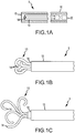
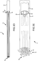
- FIGS. 1A-2D For a discussion of the device 5, reference is now made to FIGS. 1A-2D .
- the device 5 In use, and as shown in FIG. 1A , the device 5 is loaded into a catheter or other delivery device 15 in a non-expanded state. Once the surgeon has placed the delivery device 15 into the proper location, the device 5 may be pushed by a "pusher" 20 out of the delivery device 15, as indicated by FIG. 1B and into its deployed or expanded state, as indicated in FIG. 1C .
- the straightened coil device 5 (in its non-expanded shape) is deployed by advancing it down the catheter/delivery device 15, using a pusher 20, and pushing it out the distal end 16 of the delivery device 15 at the target occlusion site.
- a detachment device uniquely configured for holding and releasing the coil device 5 may be employed to control the release of the coil device by the physician.
- the fibers 10 deploy and regain their memory shape, the fibers expand, coil, and form a coil pack 35 (e.g. as illustrated in FIG. 2D ).
- the fibers 10 may push against the vessel wall 40 initially, during deployment, or near the end of deployment depending on the embodiment and depending upon the formulation of the SMP material used, which can be varied to, inter alia, increase or decrease the deployment time for the material.
- the fiber ends are biased to be positioned within the aneurysm or other vascular structure in need of occlusion.
- the multiple fibers 10, in a deployed state may have complex curl shapes, multiple size curls and/or multiple size fibers with respect to either diameter, length, or both.
- some fibers 10a may be produced larger in diameter than others to be stiffer and thereby assist in anchoring the coil pack.
- Other fibers 10b for use in the same device 5 may be produced softer, i.e., of a smaller diameter, to assist in quickly filling the pack and minimizing the coil pack length. Stiffness and softness of different fibers may also be achieved by varying the SMP formula as between different fibers to vary the material properties.
- the device 5 may be formed by 9 individual fibers 10 (members), all from the same material.
- three are 0.3048mm (0.012") in diameter and curled at a radius of 4mm, three are 0.3048mm (0.012") in diameter and curled at a radius of 3mm, and three are 0.381 mm (0.015") in diameter and curled at a radius of 2mm.
- all the coils are of a non-helical curl shape-the curl is instead more like a cloverleaf. Other curl shapes may be used.
- each fiber is 9cm long. As indicated in Fig.
- the fibers are grouped together and the proximal ends 13 of the fibers 10 are bonded by a connection member 12, such as a small plug form (e.g., in one embodiment about 5mm long).
- the forming tube may be removed after curing such that the connection member 12 operably connects the proximal ends 13 together.
- the fibers may be connected (or attached) at both a proximal end 13 and a distal end 14 of the fibers 10.
- coiling generally employs coils 10 that will retain their unique coil shape after deployment due to elastic recovery in the material, subsequent to significant storage time being held in a straight coil introducer.
- Coils 10 enter a delivery catheter 15 in the straight (pre-deployed) form and are advanced down the delivery catheter 15 using a guidewire "pusher" 20.
- Coils for cerebral aneurysm repair may utilize dedicated pushers 20 that are affixed to the coil 10 with a reliable detachment feature 30 (e.g. a retaining loop 30 or other appropriate device as discussed in more detail below and with reference to FIGS. 3C-3E ) such that the coil can be released within the aneurysm at the physician's discretion.
- a reliable detachment feature 30 e.g. a retaining loop 30 or other appropriate device as discussed in more detail below and with reference to FIGS. 3C-3E
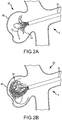
- FIGS. 2A-2D depict one embodiment of the coil device 5 within a simulated, non-symmetrical aneurysm 45.
- the device 5 is in a pre-deployed or constrained state and is being advanced down a delivery catheter 15.
- the fibers of the coil device 5 are contained within the catheter 15.
- the fibers 10 expand and begin to coil. In this way, the loose ends of the fibers 10 are contained within the aneurysm sack 45.
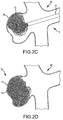
- the fibers 10 continue to advance and contact at least one wall 40 of the aneurysm 45, as shown in FIGS. 2B and 2C .
- the fibers 10 begin to form a coil mass 35, or coil pack, before the multi-fiber coil device 5 is fully deployed from the delivery device 15.
- the coil device 5 will generally fill the aneurysm 45 or a portion of the aneurysm as determined by the physician.
- the proximal end 13, 52 of the multi-fibered device 5 may unfold and have a memory configuration designed to traverse, or bridge, the opening of the aneurysm, thereby mitigating concerns about proximal ends 13, 52 loosely falling into the parent vessel.
- the intended result is achieved when the sack 45 is filled to isolate the diseased vessel wall from blood flow and blood pressure. Isolation occurs in part from the volume displacement by the coils in concert with palette formation and thrombus filling the interstitial spaces resulting in complete isolation of the aneurysm sack from the parent vessel.
- the nonmetallic, thermo-sensitive, shape memory materials provide key benefits to an aneurysm repair device.
- the shape memory coil device 5 may also be a multi-fiber device 5 wherein multiple, very small coils (fibers) 10 are delivered simultaneously to form an equivalent coil pack that would otherwise be formed by the accumulation of individual coils delivered sequentially. This simultaneous delivery and rapid formation of a coil pack provides key benefits to an aneurysm repair device.
- the device disclosed herein includes fibers that may be configured from nonmetallic, SMP materials, which are uniquely formulated to provide radiopacity to facilitate imaging under standard fluoroscopy while allowing use of CT scan and MR imaging methods, not achievable with metal coils.
- SMP material properties can be tailored, through formulation, for specific mechanical behavior of each fiber. This includes, but is not limited to: zones of differing post deployment; modulus or stiffness of the material; fiber diameter changes, including concurrent diameter changes with each zone that can enhance the relative change in stiffness along the length of each fiber; and zones of differing Tg's along the length to effect different rates of shape change and effectively time the deployment of specific fiber features.
- the acrylate- and/or thiol-based Shape Memory Polymers exhibit exceptional ( ⁇ 99%) "shape certainty” (predictable and precise material properties and dimensions for pre- and post-deployment), which enables the distinct behaviors of the fibers to enhance the functionality and utility of the device.
- polyester fibers may be incorporated into the SMP fibers or laid up in parallel with the SMP fibers during assembly for enhanced thrombogenicity.
- the pre-deployed behavior of the stored shape form enhances pushability of the device through a very small delivery catheter within a tortuous path.
- the post-deployed behavior i.e., the deployed shape form
- Post-deployed SMP material behavior can achieve a lower modulus resulting in softer fibers than achievable with metal coils or continuous traditional polymer coils. As such, more material can be packed within the aneurysm space without putting excessive pressure on the vessel wall. Therefore, the multi-fiber SMP aneurysm embolization device as disclosed herein can achieve higher packing factors in aneurysm repair than can be achieved with metal or continuous traditional polymer coils.
- the multi-fiber device 5 includes multiple, very small coils 10 (fibers) that are delivered simultaneously to form an equivalent coil pack that would otherwise be formed by the accumulation of individual coils delivered sequentially. This simultaneous delivery and rapid formation of a coil pack provides another benefit to the coil or multi-fiber embolization device disclosed herein.
- SMPs demonstrate the phenomena of shape memory based on fabricating a segregated linear block co-polymer, typically of a cross-linked hard segment and a soft segment.
- the shape memory polymer generally is characterized by defining phases that result from glass transition temperature (Tg). Mechanical properties of the phases, stored shape (e.g., below the Tg) and the deployed shape (e.g., above the Tg) as well as setting the Tg can be tailored by adjusting the formulation through different weight percentages of the monomers and cross linker. (See Patent Cooperation Treaty application nos. PCT/US2007/065691 and PCT/US2006/060297 ).
- Shape memory polymers can be formulated for a Tg that allows use of an external heat source to initiate the phase change or a Tg that utilizes the body heat of the patient to initiate the phase change.
- SMP materials are formulated for use, other ingredients can be added to the formulation to induce specific properties or behavior.
- Barium Methacrylate, Barium Acrylate, (dissolved in solution) or Tungsten or Bismuth titanate nanoparticles (held in suspension) or a combination of these or similar ingredients can be added to induce radio-opacity.
- Fibers or fabric from materials such as polyester can be added and positioned for surface exposure to induce thrombogenicity.
- Bioactive agents e.g., fibroblast growth factor
- eluting pharmaceuticals e.g., NSAID such as ibuprofen
- the material can be treated with coatings such as hydrophilic coatings to reduce friction, or biodegradable coatings (e.g., polyglycolic acid) to induce a desired tissue response.
- SMP materials enables a multiple fiber aneurysm or other vascular malformation embolic (repair) device in unique ways that cannot be reproduced in metal or non-SMP materials.
- the coil device disclosed herein provides benefits including the following: reduced procedure time, reduced procedure cost, improved ease of use and improved occlusive outcome through multiple elements.
- using a shape memory polymer formulation in a multiple fiber configuration provides for several specific device advantages and/or benefits, including, but not limited to the following:
- Fibers of unique, non-metal material formulation may provide for suitable imaging under fluoroscopy as well as offer clinical use of other imaging modalities, e.g., CT scan and MRI, that otherwise could not be used with metal devices.
- These formulations include solutions of barium methacrylate or acrylate and suspensions of titanium, tungsten, or bismuth titanate nanoparticles.
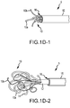
- FIGS. 3A-3E An alternate implementation of a coiled device 5 is presented in FIGS. 3A-3E .
- the elongated members 10 (fibers) are operably attached at a midpoint 50 by a retaining loop 30.
- a plurality of elongate members 10 of the device 5 may be laid out or axially aligned relative to each other in their deployed arrangement in the formation.
- the elongate members 10 of FIG. 3A may then be "stretched out" or otherwise formed in their pre-deployed state for delivery through a delivery device 15.
- the delivery device 15 may have a pusher mechanism 20 with a detachment feature, such as the retaining loop 30.
- a midpoint 50 of the elongate members is located.
- a retaining member 30, such as a retaining loop, may be disposed about and operably connected to the midpoint 50.
- the retaining loop 30 may also be operably connected to a pusher mechanism 20 of a delivery device 15.
- the elongate members 10 may be folded about the retaining loop 30, thereby creating a proximal end 52 and a distal end 54 of the plurality of elongate members 10. As shown in FIGS. 3C-3E , the proximal end 52 of the elongate members 10 is operably attached to the retaining loop 30 and will be maintained in this constrained or pre-deployed state for delivery by a delivery device 15.
- the fibers 10 at the proximal end 52 of the device 5 are folded at the proximal end 52 of the device 5 to provide several features.
- the fibers 10 at the proximal end 52 are continuous (i.e., the free ends of each fiber are at the distal end 54 and are deployed simultaneously), which may avoid or decrease the need for meticulous placement and release of the proximal end 52.
- free proximal ends of single fibers deployed serially in the prior art are generally deployed well inside the coil pack so that the proximal end of the coil device doesn't migrate into the parent vessel.
- the continuous fibers at the proximal end transverse, or bridge, the opening (neck) of the aneurysm, thereby providing a scaffold or frame over the opening without having exposed ends.
- the retention loop feature 30 over the folded multiple fibers 10 provides simple attachment with and detachment from the fibers to retain them in the dedicated "pusher" until released by the physician.
- Detachment may be achieved by one of multiple means utilizing this primary retention loop feature 30, looped over the center 50 of these multiple fibers 10. Detachment of the retention loop 30 releases the center 50 of the multiple fibers 10. Any of several methods may be used to release the retention loop 30.
- the loop material may extend to the proximal end of the pusher allowing the physician to release the loop directly.
- a mechanical means translates via the pusher to the proximal end to cut or otherwise release one end of the retention loop 30.
- each fiber 10 can be fabricated from SMP materials of different formulations that result in varying stiffness along the length of the fiber, e.g., allowing a zone of loops to be stiff to anchor and the balance of the fiber to be soft for improved packing efficiency. Additionally, this material effect can be combined with diameter (dimensional) changes along the coil length to enhance achieving specific fiber stiffness in different regions along the device. Limitations found in metal wire forming inhibit this ability in other metal embolic coils.
- the "shape certainty" of SMP material provides the ability to accurately define and provide a straighter insertion configuration that flexes and tracks down the long, small lumen of a delivery catheter placed in the body in a tortuous path to reach the target site, and separately define and provide a deployment configuration of a complex "secondary" fiber/coil shape that enables an efficient occlusive mass.
- SMA shape memory alloys
- These definitive shapes and features enable using a low cost fabricated SMP device in comparison to high cost shape memory alloys (SMA) such as Nitinol, or, in comparison to traditional polymers without shape memory.
- SMA shape memory alloys
- Traditional polymers without shape memory undergo continuous stress in a constrained, straight packaged configuration and could not survive the shelf life and packaging duration necessary and retain appropriate post deployment shape, i.e., traditional polymer materials do not exhibit "shape certainty.”
- SMP devices from acrylate formulations are durable implants and do not suffer from metabolic attack and degradation over time. These devices are intentionally not biodegradable but remain in the body for integration with thrombus and eventual tissue ingrowth as a permanent implant.
- other ingredients can be added to the formulation to induce specific properties or behavior that may include radio-opacity, computed tomography (CT) compatibility, tissue response, thrombogenicity, and others, or combination thereof.
- CT computed tomography
- rate of shape change is directly correlated to properties defined by the formulation (e.g., Tg and modulus slope at transition) relative to the temperature at which deployment occurs. Rate of shape change can be adjusted for the same deployment temperature (e.g., body core temperature) through different material formulations. This supports the ability of specific features being deployed in time before other features (e.g., anchoring) occur prior to filling.
- multiple coils within a given diameter of the delivery catheter, multiple coils (smaller and varying in diameter if desired) can be configured adjacent to each other resulting in a pre-deployed size that fits within the single catheter lumen. Upon deployment, the multiple coils are expressed from the catheter, change shape, and quickly generate a much more complex coil mass than could be achieved by expressing a single coil.
- each fiber works in concert with the others to achieve the total device performance.
- each fiber is defined and formed with specific curl and arc dimensions across a specific length.
- the length of the fiber is double the length of the coil device in a pre-deployed state.
- each fiber can reflect changing diameters along its length and be fabricated with different SMP formulations to develop zones of different effective post-deployment stiffness. Zones of stiffer sections utilizing larger curls and arcs may be established to facilitate anchoring in the aneurysm and reduce any propensity of the coil pack from falling out of the aneurysm opening or neck.
- zones of softer sections utilizing smaller curls and arcs are established to facilitate easy compacting such that the material fills the interior aneurysm space to very high packing factors. Zones may also be imposed that reflect differing Tg such that the shape change for each zone is tuned to occur in a specific sequence-the zones may align or differ.
- Each end of the individual fiber further be defined with specific curl size, material stiffness and Tg such that these ends will wrap, in some embodiments, immediately upon deployment and be retained within the aneurysm sack.
- fibers having different diameters from each other i.e., the diameter of each fiber is consistent along its length
- the diameter of each fiber is consistent along its length
- Grouped Fiber Configurations to size the aneurysm device A specific number of individual fibers, of specific length, are grouped together that reflect the desired volume to be displaced and establish the labeled size of the coil device. The fibers are laid parallel to each other.
- a retaining loop 30 (e.g., monofilament) is placed across the center 50 of the fibers 10 and the fibers are folded to form the proximal end 52 at the fold/loop (see FIGS. 3A-3E ).
- the number of folded fibers of a certain fiber diameter establishes the size of the catheter lumen that the device can be placed into and passed for deployment.
- the fiber's distal ends are generally even. In other embodiments, the fiber's distal ends are uneven.
- the loop is connected to the pusher's detachment mechanism.
- the fibers are heated above the highest Tg, and then placed/pulled into a constraining fixture that causes the fibers to straighten and conform to a total diameter slightly less than the associated delivery catheter size.
- the fibers may then be placed (before or after cooling) into a dedicated "introducer” that provides the constrained packaging for the fibers.
- the fibers maintain their pre-deployed shape regardless of the environmental temperature. Because the SMP material is a cross-linked polymer, the fibers maintain their shape memory (“shape certainty") through such temperature changes.
- shape certainty shape memory
- the device fibers are thereby easily advanced through the introducer into the proximal end of a placed delivery catheter of the physician's choice.
- the device/fibers are then advanced with the dedicated pusher to the aneurysm site and deployed into the sack. Once the pusher has reached the distal end of the catheter, the physician activates detachment and the device is released. The physician then determines if any additional devices or individual coils would be beneficial to achieving the highest possible packing factor.
- the multi-fiber SMP aneurysm embolic or coiling device 5 and its various configurations as disclosed herein address current key clinical deficiencies that are unmet with existing metal and single polymer coils (and other devices and their associated challenges discussed herein).
- the SMP coil devices disclosed here address these clinical deficiencies by the following:
Landscapes
- Health & Medical Sciences (AREA)
- Life Sciences & Earth Sciences (AREA)
- Surgery (AREA)
- Veterinary Medicine (AREA)
- Heart & Thoracic Surgery (AREA)
- Public Health (AREA)
- General Health & Medical Sciences (AREA)
- Animal Behavior & Ethology (AREA)
- Vascular Medicine (AREA)
- Biomedical Technology (AREA)
- Engineering & Computer Science (AREA)
- Medical Informatics (AREA)
- Molecular Biology (AREA)
- Nuclear Medicine, Radiotherapy & Molecular Imaging (AREA)
- Reproductive Health (AREA)
- Neurosurgery (AREA)
- Epidemiology (AREA)
- Anesthesiology (AREA)
- Hematology (AREA)
- Surgical Instruments (AREA)
Claims (13)
- Formspeichernde Coiling-Vorrichtung (5) zum Verschließen eines Gefäßes oder eines anderen vaskulären Targets, umfassend:eine Vielzahl von einzelnen gewundenen Elementen (10), die in einem Formierungszustand eines formspeichernden Polymermaterials gebildet wurden, wobeidie gewundenen Elemente (10) in einem Zustand vor der Auslösung als Vielzahl von länglichen Elementen (10) zusammengehalten werden, die zur Abgabe durch eine Abgabevorrichtung ausgelegt sind, an einem proximalen Ende (13) der Vorrichtung (5) aneinander angebracht sind, an einem distalen Ende (14) der Vorrichtung (5) frei voneinander und achsparallel zueinander und zur Abgabevorrichtung ausgerichtet sind; unddie länglichen Elemente (10) in einem ausgelösten Zustand aufgrund einer thermomechanischen Reaktion zur Bildung der Vielzahl von gewundenen Elementen (10) am proximalen Ende (13) der Vorrichtung (5) zurückkehren und getrennt komplexe gewundene Formen definieren, um ein dichtes Spulenpaket zum Füllen des Targets zu bilden; undin einem Zustand während der Auslösung zwischen dem Zustand vor der Auslösung und dem ausgelösten Zustand mindestens eines der Vielzahl von länglichen Elementen (10) zum Verankern der Coiling-Vorrichtung (5) beim Füllen des vaskulären Targets und Zurückkehren zur Form eines gewundenen Elements (10) ausgelegt ist.
- Coiling-Vorrichtung nach Anspruch 1, wobei
die Vielzahl von länglichen Elementen (10) an einem Zwischenpunkt eines jeden der Vielzahl von länglichen Elementen zusammengefaltet ist und/oder
die Vielzahl von länglichen Elementen (10) an einem Zwischenpunkt eines jeden der Vielzahl von länglichen Elementen miteinander verbunden ist. - Coiling-Vorrichtung nach Anspruch 1, wobei
die Vielzahl von gewundenen Elementen (10) Elemente beinhaltet, die untereinander verschiedene Windungen sowie Bogenformen und -größen aufweisen; und/oder
zwei oder mehr der gewundenen Elemente voneinander abweichende Durchmesser haben; und/oder
eines oder mehrere der gewundenen Elemente spiralförmig ist/sind. - Coiling-Vorrichtung nach Anspruch 1, wobei mindestens eines der Vielzahl von gewundenen Elementen mindestens zwei Materialzonen mit unterschiedlichen Materialeigenschaften, die aus der Gruppe umfassend einen Modul und eine Glasübergangstemperatur (Tg) ausgewählt sind, umfasst.
- Coiling-Vorrichtung nach Anspruch 1, wobei
jedes von zwei oder mehr der Vielzahl von gewundenen Elementen mindestens zwei Materialzonen mit unterschiedlichen Materialeigenschaften, die aus der Gruppe umfassend einen Modul und eine Glasübergangstemperatur (Tg) ausgewählt sind, umfasst; und
die mindestens zwei Materialzonen an jedem einzelnen länglichen Element ausgerichtet sind; oder
die mindestens zwei Materialzonen nicht an jedem einzelnen länglichen Element ausgerichtet sind. - Coiling-Vorrichtung nach Anspruch 1, wobei
jedes der Vielzahl von länglichen Elementen eine gleiche Länge hat; oder
zwei oder mehrere der Vielzahl von länglichen Elementen eine unterschiedliche Länge haben. - Verfahren zur Herstellung einer formspeichernden Coiling-Vorrichtung (5) zum Verschließen eines vaskulären Targets, umfassend:Bereitstellen eines formspeichernden Polymermaterials;Ausbilden einer Vielzahl von einzelnen gewundenen Elementen (10) aus dem formspeichernden Polymermaterial in einem Formierungszustand;Ausbilden mindestens eines der einzelnen gewundenen Elemente (10) in einer Konfiguration zum Verankern der Coiling-Vorrichtung (5) beim Füllen des vaskulären Targets mit den einzelnen gewundenen Elementen (10);Anbringen der Vielzahl von einzelnen gewundenen Elementen (10) aneinander an einem proximalen Ende (13) der Vorrichtung (5), während die gewundenen Elemente (10) am distalen Ende (14) der Vorrichtung frei voneinander belassen werden;Zusammenhalten der Vielzahl von gewundenen Elementen (10) in einem Zustand vor der Auslösung als Vielzahl von länglichen Elementen (10); undAnordnen der Vielzahl von länglichen Elementen (10) achsparallel zueinander.
- Verfahren nach Anspruch 7, ferner umfassend:Ausbilden eines oder mehrerer der Vielzahl von gewundenen Elementen (10) als Spiralform im Formierungszustand; und/oderAusbilden von zwei oder mehreren der Vielzahl von gewundenen Elementen (10) mit voneinander verschiedenem Durchmesser im Formierungszustand; und/oderAusbilden von Elementen der Vielzahl von gewundenen Elementen mit untereinander verschiedenen Windungen und Bogenformen und -größen im Formierungszustand.
- Verfahren nach Anspruch 7, wobei jedes der Vielzahl von gewundenen Elementen (10) mindestens zwei Zonen von formspeicherndem Polymermaterial aufweist, wobei jede Zone einen anderen Modul oder eine andere Glasübergangstemperatur (Tg) oder beides aufweist.
- Verfahren nach Anspruch 7, wobei jedes der Vielzahl von länglichen Elementen ein proximales Ende (13) und ein distales Ende (14) aufweist und der Schritt des Anbringens ferner ein Verbinden der proximalen Enden eines jeden der Vielzahl von länglichen Elementen miteinander umfasst.
- Verfahren nach Anspruch 10, ferner umfassend:Bereitstellen einer Abgabevorrichtung (20), die einen Schubmechanismus mit einer Abtrennfunktion (30) aufweist; undbetriebsfähiges Anbringen der miteinander verbundenen proximalen Enden der Vielzahl von länglichen Elementen an der Abtrennfunktion (30) des Schubmechanismus der Abgabevorrichtung (20).
- Verfahren nach Anspruch 7, weiterhin umfassend:Bereitstellen einer Halteschlaufe über einen Zwischenpunkt jedes einzelnen Elements der Vielzahl von länglichen Elementen; undFalten der Vielzahl von länglichen Elementen um die Halteschlaufe zur Bildung eines proximalen Endes (13) an der Halteschlaufe und eines distalen Endes (54) der Vielzahl von länglichen Elementen an benachbarten freien Enden der Vielzahl von länglichen Elementen.
- Verfahren nach Anspruch 12, ferner umfassend:Bereitstellen einer Abgabevorrichtung (20), die einen Schubmechanismus mit einer Abtrennfunktion (30) aufweist; undbetriebsfähiges Anbringen des proximalen Endes (13) an der Abtrennfunktion (30) des Schubmechanismus der Abgabevorrichtung.
Applications Claiming Priority (2)
| Application Number | Priority Date | Filing Date | Title |
|---|---|---|---|
| US28695509P | 2009-12-16 | 2009-12-16 | |
| PCT/US2010/060598 WO2011084536A2 (en) | 2009-12-16 | 2010-12-15 | Multi-fiber shape memory device |
Publications (3)
| Publication Number | Publication Date |
|---|---|
| EP2512352A2 EP2512352A2 (de) | 2012-10-24 |
| EP2512352A4 EP2512352A4 (de) | 2015-01-07 |
| EP2512352B1 true EP2512352B1 (de) | 2017-09-27 |
Family
ID=44306045
Family Applications (1)
| Application Number | Title | Priority Date | Filing Date |
|---|---|---|---|
| EP10842570.3A Not-in-force EP2512352B1 (de) | 2009-12-16 | 2010-12-15 | Formspeichernde mehrfaservorrichtung |
Country Status (6)
| Country | Link |
|---|---|
| US (1) | US20130085518A1 (de) |
| EP (1) | EP2512352B1 (de) |
| JP (1) | JP5727510B2 (de) |
| AU (1) | AU2010339980C1 (de) |
| CA (1) | CA2784293C (de) |
| WO (1) | WO2011084536A2 (de) |
Families Citing this family (16)
| Publication number | Priority date | Publication date | Assignee | Title |
|---|---|---|---|---|
| EP2162101B1 (de) | 2007-06-25 | 2019-02-20 | MicroVention, Inc. | Selbstexpandierende prothese |
| US10716573B2 (en) | 2008-05-01 | 2020-07-21 | Aneuclose | Janjua aneurysm net with a resilient neck-bridging portion for occluding a cerebral aneurysm |
| US10028747B2 (en) | 2008-05-01 | 2018-07-24 | Aneuclose Llc | Coils with a series of proximally-and-distally-connected loops for occluding a cerebral aneurysm |
| EP2520233B1 (de) | 2009-04-02 | 2017-11-01 | Endoshape, Inc. | Gefässverschlussvorrichtungen |
| US9358140B1 (en) | 2009-11-18 | 2016-06-07 | Aneuclose Llc | Stent with outer member to embolize an aneurysm |
| CA2835427A1 (en) | 2011-05-11 | 2012-11-15 | Microvention, Inc. | Device for occluding a lumen |
| US20130035665A1 (en) * | 2011-08-05 | 2013-02-07 | W. L. Gore & Associates, Inc. | Polymer-Based Occlusion Devices, Systems and Methods |
| AU2013209672B2 (en) * | 2012-01-17 | 2015-11-19 | Endoshape, Inc. | Occlusion device for a vascular or biological lumen |
| EP2806823B1 (de) * | 2012-01-26 | 2019-07-31 | Endoshape, Inc. | Systeme und vorrichtungen zur freisetzung einer lumenokklusionsvorrichtung unter verwendung einer distalen und/oder proximalen steuerung |
| CN105073031B (zh) | 2013-03-13 | 2017-10-27 | 内形有限公司 | 连续栓塞线圈及其输送方法和装置 |
| US9968432B2 (en) | 2013-06-28 | 2018-05-15 | Cook Medical Technologies Llc | Occlusion device including bundle of occlusion wires having preformed shapes |
| CN105899150B (zh) | 2013-07-31 | 2018-07-27 | Neuvt 有限公司 | 用于血管内栓塞的方法和装置 |
| US10010328B2 (en) | 2013-07-31 | 2018-07-03 | NeuVT Limited | Endovascular occlusion device with hemodynamically enhanced sealing and anchoring |
| US9675361B2 (en) | 2014-02-28 | 2017-06-13 | Cook Medical Technologies Llc | Coil occlusion device |
| WO2016056632A1 (ja) * | 2014-10-08 | 2016-04-14 | イービーエム株式会社 | 血管治療評価システム、そのコンピュータソフトウエアプログラム及び方法 |
| US11253266B2 (en) | 2015-08-25 | 2022-02-22 | Endoshape, Inc. | Sleeve for delivery of embolic coil |
Family Cites Families (15)
| Publication number | Priority date | Publication date | Assignee | Title |
|---|---|---|---|---|
| US6146373A (en) * | 1997-10-17 | 2000-11-14 | Micro Therapeutics, Inc. | Catheter system and method for injection of a liquid embolic composition and a solidification agent |
| US6136015A (en) | 1998-08-25 | 2000-10-24 | Micrus Corporation | Vasoocclusive coil |
| US6159165A (en) * | 1997-12-05 | 2000-12-12 | Micrus Corporation | Three dimensional spherical micro-coils manufactured from radiopaque nickel-titanium microstrand |
| US6790218B2 (en) * | 1999-12-23 | 2004-09-14 | Swaminathan Jayaraman | Occlusive coil manufacture and delivery |
| US6589265B1 (en) * | 2000-10-31 | 2003-07-08 | Endovascular Technologies, Inc. | Intrasaccular embolic device |
| US20040193246A1 (en) * | 2003-03-25 | 2004-09-30 | Microvention, Inc. | Methods and apparatus for treating aneurysms and other vascular defects |
| US8043321B2 (en) * | 2003-07-24 | 2011-10-25 | Boston Scientific Scimed, Inc. | Embolic coil |
| ES2321300T3 (es) * | 2004-09-22 | 2009-06-04 | Dendron Gmbh | Implante medico. |
| US20070239199A1 (en) * | 2006-03-31 | 2007-10-11 | Swaminathan Jayaraman | Inferior vena cava filter |
| US7901444B2 (en) * | 2006-09-29 | 2011-03-08 | Codman & Shurtleff, Inc. | Embolic coil delivery system with mechanical release mechanism |
| US9414842B2 (en) * | 2007-10-12 | 2016-08-16 | St. Jude Medical, Cardiology Division, Inc. | Multi-component vascular device |
| US20090227976A1 (en) | 2008-03-05 | 2009-09-10 | Calabria Marie F | Multiple biocompatible polymeric strand aneurysm embolization system and method |
| CA2722672C (en) | 2008-05-02 | 2019-10-22 | Sequent Medical Inc. | Filamentary devices for treatment of vascular defects |
| US8262692B2 (en) * | 2008-09-05 | 2012-09-11 | Merlin Md Pte Ltd | Endovascular device |
| EP2520233B1 (de) | 2009-04-02 | 2017-11-01 | Endoshape, Inc. | Gefässverschlussvorrichtungen |
-
2010
- 2010-12-15 US US13/516,549 patent/US20130085518A1/en not_active Abandoned
- 2010-12-15 EP EP10842570.3A patent/EP2512352B1/de not_active Not-in-force
- 2010-12-15 AU AU2010339980A patent/AU2010339980C1/en not_active Ceased
- 2010-12-15 CA CA2784293A patent/CA2784293C/en not_active Expired - Fee Related
- 2010-12-15 WO PCT/US2010/060598 patent/WO2011084536A2/en active Application Filing
- 2010-12-15 JP JP2012544799A patent/JP5727510B2/ja not_active Expired - Fee Related
Non-Patent Citations (1)
| Title |
|---|
| None * |
Also Published As
| Publication number | Publication date |
|---|---|
| EP2512352A2 (de) | 2012-10-24 |
| AU2010339980A1 (en) | 2012-06-21 |
| AU2010339980C1 (en) | 2014-07-10 |
| WO2011084536A3 (en) | 2011-11-03 |
| JP5727510B2 (ja) | 2015-06-03 |
| US20130085518A1 (en) | 2013-04-04 |
| EP2512352A4 (de) | 2015-01-07 |
| AU2010339980B2 (en) | 2014-04-24 |
| WO2011084536A2 (en) | 2011-07-14 |
| CA2784293A1 (en) | 2011-07-14 |
| JP2013514157A (ja) | 2013-04-25 |
| CA2784293C (en) | 2015-01-27 |
Similar Documents
| Publication | Publication Date | Title |
|---|---|---|
| EP2512352B1 (de) | Formspeichernde mehrfaservorrichtung | |
| EP2520233B1 (de) | Gefässverschlussvorrichtungen | |
| JP7227307B2 (ja) | 閉塞デバイス | |
| JP6841874B2 (ja) | 閉塞デバイス | |
| JP6364354B2 (ja) | 遠位および/または近位制御を用いて管腔閉塞デバイスを送達するためのシステム、デバイス、および方法 | |
| JP4472525B2 (ja) | 血管障害部位の塞栓具 | |
| US20050107823A1 (en) | Anchored stent and occlusive device for treatment of aneurysms | |
| JP7350858B2 (ja) | 血管閉塞デバイス |
Legal Events
| Date | Code | Title | Description |
|---|---|---|---|
| PUAI | Public reference made under article 153(3) epc to a published international application that has entered the european phase |
Free format text: ORIGINAL CODE: 0009012 |
|
| 17P | Request for examination filed |
Effective date: 20120626 |
|
| AK | Designated contracting states |
Kind code of ref document: A2 Designated state(s): AL AT BE BG CH CY CZ DE DK EE ES FI FR GB GR HR HU IE IS IT LI LT LU LV MC MK MT NL NO PL PT RO RS SE SI SK SM TR |
|
| DAX | Request for extension of the european patent (deleted) | ||
| A4 | Supplementary search report drawn up and despatched |
Effective date: 20141208 |
|
| RIC1 | Information provided on ipc code assigned before grant |
Ipc: A61L 31/04 20060101ALI20141202BHEP Ipc: A61B 17/12 20060101AFI20141202BHEP Ipc: A61M 25/01 20060101ALI20141202BHEP Ipc: A61L 27/14 20060101ALI20141202BHEP |
|
| GRAP | Despatch of communication of intention to grant a patent |
Free format text: ORIGINAL CODE: EPIDOSNIGR1 |
|
| INTG | Intention to grant announced |
Effective date: 20170418 |
|
| GRAS | Grant fee paid |
Free format text: ORIGINAL CODE: EPIDOSNIGR3 |
|
| GRAA | (expected) grant |
Free format text: ORIGINAL CODE: 0009210 |
|
| AK | Designated contracting states |
Kind code of ref document: B1 Designated state(s): AL AT BE BG CH CY CZ DE DK EE ES FI FR GB GR HR HU IE IS IT LI LT LU LV MC MK MT NL NO PL PT RO RS SE SI SK SM TR |
|
| REG | Reference to a national code |
Ref country code: GB Ref legal event code: FG4D |
|
| REG | Reference to a national code |
Ref country code: CH Ref legal event code: EP |
|
| REG | Reference to a national code |
Ref country code: AT Ref legal event code: REF Ref document number: 931241 Country of ref document: AT Kind code of ref document: T Effective date: 20171015 |
|
| REG | Reference to a national code |
Ref country code: IE Ref legal event code: FG4D |
|
| REG | Reference to a national code |
Ref country code: DE Ref legal event code: R096 Ref document number: 602010045635 Country of ref document: DE |
|
| REG | Reference to a national code |
Ref country code: FR Ref legal event code: PLFP Year of fee payment: 8 |
|
| PG25 | Lapsed in a contracting state [announced via postgrant information from national office to epo] |
Ref country code: HR Free format text: LAPSE BECAUSE OF FAILURE TO SUBMIT A TRANSLATION OF THE DESCRIPTION OR TO PAY THE FEE WITHIN THE PRESCRIBED TIME-LIMIT Effective date: 20170927 Ref country code: FI Free format text: LAPSE BECAUSE OF FAILURE TO SUBMIT A TRANSLATION OF THE DESCRIPTION OR TO PAY THE FEE WITHIN THE PRESCRIBED TIME-LIMIT Effective date: 20170927 Ref country code: NO Free format text: LAPSE BECAUSE OF FAILURE TO SUBMIT A TRANSLATION OF THE DESCRIPTION OR TO PAY THE FEE WITHIN THE PRESCRIBED TIME-LIMIT Effective date: 20171227 Ref country code: LT Free format text: LAPSE BECAUSE OF FAILURE TO SUBMIT A TRANSLATION OF THE DESCRIPTION OR TO PAY THE FEE WITHIN THE PRESCRIBED TIME-LIMIT Effective date: 20170927 Ref country code: SE Free format text: LAPSE BECAUSE OF FAILURE TO SUBMIT A TRANSLATION OF THE DESCRIPTION OR TO PAY THE FEE WITHIN THE PRESCRIBED TIME-LIMIT Effective date: 20170927 |
|
| REG | Reference to a national code |
Ref country code: NL Ref legal event code: MP Effective date: 20170927 |
|
| REG | Reference to a national code |
Ref country code: LT Ref legal event code: MG4D |
|
| REG | Reference to a national code |
Ref country code: AT Ref legal event code: MK05 Ref document number: 931241 Country of ref document: AT Kind code of ref document: T Effective date: 20170927 |
|
| PG25 | Lapsed in a contracting state [announced via postgrant information from national office to epo] |
Ref country code: RS Free format text: LAPSE BECAUSE OF FAILURE TO SUBMIT A TRANSLATION OF THE DESCRIPTION OR TO PAY THE FEE WITHIN THE PRESCRIBED TIME-LIMIT Effective date: 20170927 Ref country code: LV Free format text: LAPSE BECAUSE OF FAILURE TO SUBMIT A TRANSLATION OF THE DESCRIPTION OR TO PAY THE FEE WITHIN THE PRESCRIBED TIME-LIMIT Effective date: 20170927 Ref country code: GR Free format text: LAPSE BECAUSE OF FAILURE TO SUBMIT A TRANSLATION OF THE DESCRIPTION OR TO PAY THE FEE WITHIN THE PRESCRIBED TIME-LIMIT Effective date: 20171228 Ref country code: BG Free format text: LAPSE BECAUSE OF FAILURE TO SUBMIT A TRANSLATION OF THE DESCRIPTION OR TO PAY THE FEE WITHIN THE PRESCRIBED TIME-LIMIT Effective date: 20171227 |
|
| PG25 | Lapsed in a contracting state [announced via postgrant information from national office to epo] |
Ref country code: NL Free format text: LAPSE BECAUSE OF FAILURE TO SUBMIT A TRANSLATION OF THE DESCRIPTION OR TO PAY THE FEE WITHIN THE PRESCRIBED TIME-LIMIT Effective date: 20170927 |
|
| PG25 | Lapsed in a contracting state [announced via postgrant information from national office to epo] |
Ref country code: ES Free format text: LAPSE BECAUSE OF FAILURE TO SUBMIT A TRANSLATION OF THE DESCRIPTION OR TO PAY THE FEE WITHIN THE PRESCRIBED TIME-LIMIT Effective date: 20170927 Ref country code: CZ Free format text: LAPSE BECAUSE OF FAILURE TO SUBMIT A TRANSLATION OF THE DESCRIPTION OR TO PAY THE FEE WITHIN THE PRESCRIBED TIME-LIMIT Effective date: 20170927 Ref country code: RO Free format text: LAPSE BECAUSE OF FAILURE TO SUBMIT A TRANSLATION OF THE DESCRIPTION OR TO PAY THE FEE WITHIN THE PRESCRIBED TIME-LIMIT Effective date: 20170927 |
|
| PG25 | Lapsed in a contracting state [announced via postgrant information from national office to epo] |
Ref country code: IS Free format text: LAPSE BECAUSE OF FAILURE TO SUBMIT A TRANSLATION OF THE DESCRIPTION OR TO PAY THE FEE WITHIN THE PRESCRIBED TIME-LIMIT Effective date: 20180127 Ref country code: IT Free format text: LAPSE BECAUSE OF FAILURE TO SUBMIT A TRANSLATION OF THE DESCRIPTION OR TO PAY THE FEE WITHIN THE PRESCRIBED TIME-LIMIT Effective date: 20170927 Ref country code: SK Free format text: LAPSE BECAUSE OF FAILURE TO SUBMIT A TRANSLATION OF THE DESCRIPTION OR TO PAY THE FEE WITHIN THE PRESCRIBED TIME-LIMIT Effective date: 20170927 Ref country code: EE Free format text: LAPSE BECAUSE OF FAILURE TO SUBMIT A TRANSLATION OF THE DESCRIPTION OR TO PAY THE FEE WITHIN THE PRESCRIBED TIME-LIMIT Effective date: 20170927 Ref country code: AT Free format text: LAPSE BECAUSE OF FAILURE TO SUBMIT A TRANSLATION OF THE DESCRIPTION OR TO PAY THE FEE WITHIN THE PRESCRIBED TIME-LIMIT Effective date: 20170927 Ref country code: SM Free format text: LAPSE BECAUSE OF FAILURE TO SUBMIT A TRANSLATION OF THE DESCRIPTION OR TO PAY THE FEE WITHIN THE PRESCRIBED TIME-LIMIT Effective date: 20170927 |
|
| REG | Reference to a national code |
Ref country code: DE Ref legal event code: R097 Ref document number: 602010045635 Country of ref document: DE |
|
| PG25 | Lapsed in a contracting state [announced via postgrant information from national office to epo] |
Ref country code: DK Free format text: LAPSE BECAUSE OF FAILURE TO SUBMIT A TRANSLATION OF THE DESCRIPTION OR TO PAY THE FEE WITHIN THE PRESCRIBED TIME-LIMIT Effective date: 20170927 |
|
| REG | Reference to a national code |
Ref country code: CH Ref legal event code: PL |
|
| PLBE | No opposition filed within time limit |
Free format text: ORIGINAL CODE: 0009261 |
|
| STAA | Information on the status of an ep patent application or granted ep patent |
Free format text: STATUS: NO OPPOSITION FILED WITHIN TIME LIMIT |
|
| PG25 | Lapsed in a contracting state [announced via postgrant information from national office to epo] |
Ref country code: PL Free format text: LAPSE BECAUSE OF FAILURE TO SUBMIT A TRANSLATION OF THE DESCRIPTION OR TO PAY THE FEE WITHIN THE PRESCRIBED TIME-LIMIT Effective date: 20170927 |
|
| 26N | No opposition filed |
Effective date: 20180628 |
|
| REG | Reference to a national code |
Ref country code: IE Ref legal event code: MM4A |
|
| PG25 | Lapsed in a contracting state [announced via postgrant information from national office to epo] |
Ref country code: MT Free format text: LAPSE BECAUSE OF NON-PAYMENT OF DUE FEES Effective date: 20171215 Ref country code: LU Free format text: LAPSE BECAUSE OF NON-PAYMENT OF DUE FEES Effective date: 20171215 |
|
| REG | Reference to a national code |
Ref country code: BE Ref legal event code: MM Effective date: 20171231 |
|
| PG25 | Lapsed in a contracting state [announced via postgrant information from national office to epo] |
Ref country code: IE Free format text: LAPSE BECAUSE OF NON-PAYMENT OF DUE FEES Effective date: 20171215 |
|
| PG25 | Lapsed in a contracting state [announced via postgrant information from national office to epo] |
Ref country code: SI Free format text: LAPSE BECAUSE OF FAILURE TO SUBMIT A TRANSLATION OF THE DESCRIPTION OR TO PAY THE FEE WITHIN THE PRESCRIBED TIME-LIMIT Effective date: 20170927 Ref country code: LI Free format text: LAPSE BECAUSE OF NON-PAYMENT OF DUE FEES Effective date: 20171231 Ref country code: CH Free format text: LAPSE BECAUSE OF NON-PAYMENT OF DUE FEES Effective date: 20171231 Ref country code: BE Free format text: LAPSE BECAUSE OF NON-PAYMENT OF DUE FEES Effective date: 20171231 |
|
| PG25 | Lapsed in a contracting state [announced via postgrant information from national office to epo] |
Ref country code: HU Free format text: LAPSE BECAUSE OF FAILURE TO SUBMIT A TRANSLATION OF THE DESCRIPTION OR TO PAY THE FEE WITHIN THE PRESCRIBED TIME-LIMIT; INVALID AB INITIO Effective date: 20101215 Ref country code: MC Free format text: LAPSE BECAUSE OF FAILURE TO SUBMIT A TRANSLATION OF THE DESCRIPTION OR TO PAY THE FEE WITHIN THE PRESCRIBED TIME-LIMIT Effective date: 20170927 |
|
| PG25 | Lapsed in a contracting state [announced via postgrant information from national office to epo] |
Ref country code: CY Free format text: LAPSE BECAUSE OF NON-PAYMENT OF DUE FEES Effective date: 20170927 |
|
| PG25 | Lapsed in a contracting state [announced via postgrant information from national office to epo] |
Ref country code: MK Free format text: LAPSE BECAUSE OF FAILURE TO SUBMIT A TRANSLATION OF THE DESCRIPTION OR TO PAY THE FEE WITHIN THE PRESCRIBED TIME-LIMIT Effective date: 20170927 |
|
| PG25 | Lapsed in a contracting state [announced via postgrant information from national office to epo] |
Ref country code: TR Free format text: LAPSE BECAUSE OF FAILURE TO SUBMIT A TRANSLATION OF THE DESCRIPTION OR TO PAY THE FEE WITHIN THE PRESCRIBED TIME-LIMIT Effective date: 20170927 |
|
| PG25 | Lapsed in a contracting state [announced via postgrant information from national office to epo] |
Ref country code: PT Free format text: LAPSE BECAUSE OF FAILURE TO SUBMIT A TRANSLATION OF THE DESCRIPTION OR TO PAY THE FEE WITHIN THE PRESCRIBED TIME-LIMIT Effective date: 20170927 |
|
| PG25 | Lapsed in a contracting state [announced via postgrant information from national office to epo] |
Ref country code: AL Free format text: LAPSE BECAUSE OF FAILURE TO SUBMIT A TRANSLATION OF THE DESCRIPTION OR TO PAY THE FEE WITHIN THE PRESCRIBED TIME-LIMIT Effective date: 20170927 |
|
| PGFP | Annual fee paid to national office [announced via postgrant information from national office to epo] |
Ref country code: FR Payment date: 20201223 Year of fee payment: 11 |
|
| PGFP | Annual fee paid to national office [announced via postgrant information from national office to epo] |
Ref country code: DE Payment date: 20211210 Year of fee payment: 12 Ref country code: GB Payment date: 20211209 Year of fee payment: 12 |
|
| PG25 | Lapsed in a contracting state [announced via postgrant information from national office to epo] |
Ref country code: FR Free format text: LAPSE BECAUSE OF NON-PAYMENT OF DUE FEES Effective date: 20211231 |
|
| REG | Reference to a national code |
Ref country code: DE Ref legal event code: R119 Ref document number: 602010045635 Country of ref document: DE |
|
| GBPC | Gb: european patent ceased through non-payment of renewal fee |
Effective date: 20221215 |
|
| PG25 | Lapsed in a contracting state [announced via postgrant information from national office to epo] |
Ref country code: GB Free format text: LAPSE BECAUSE OF NON-PAYMENT OF DUE FEES Effective date: 20221215 Ref country code: DE Free format text: LAPSE BECAUSE OF NON-PAYMENT OF DUE FEES Effective date: 20230701 |