EP2511606B1 - Dispositif de lampe - Google Patents
Dispositif de lampe Download PDFInfo
- Publication number
- EP2511606B1 EP2511606B1 EP12176009.4A EP12176009A EP2511606B1 EP 2511606 B1 EP2511606 B1 EP 2511606B1 EP 12176009 A EP12176009 A EP 12176009A EP 2511606 B1 EP2511606 B1 EP 2511606B1
- Authority
- EP
- European Patent Office
- Prior art keywords
- heat radiating
- lamp device
- substrate
- fins
- opening
- Prior art date
- Legal status (The legal status is an assumption and is not a legal conclusion. Google has not performed a legal analysis and makes no representation as to the accuracy of the status listed.)
- Active
Links
Images

Classifications
-
- F—MECHANICAL ENGINEERING; LIGHTING; HEATING; WEAPONS; BLASTING
- F21—LIGHTING
- F21V—FUNCTIONAL FEATURES OR DETAILS OF LIGHTING DEVICES OR SYSTEMS THEREOF; STRUCTURAL COMBINATIONS OF LIGHTING DEVICES WITH OTHER ARTICLES, NOT OTHERWISE PROVIDED FOR
- F21V29/00—Protecting lighting devices from thermal damage; Cooling or heating arrangements specially adapted for lighting devices or systems
- F21V29/50—Cooling arrangements
- F21V29/70—Cooling arrangements characterised by passive heat-dissipating elements, e.g. heat-sinks
- F21V29/74—Cooling arrangements characterised by passive heat-dissipating elements, e.g. heat-sinks with fins or blades
- F21V29/77—Cooling arrangements characterised by passive heat-dissipating elements, e.g. heat-sinks with fins or blades with essentially identical diverging planar fins or blades, e.g. with fan-like or star-like cross-section
-
- G—PHYSICS
- G02—OPTICS
- G02B—OPTICAL ELEMENTS, SYSTEMS OR APPARATUS
- G02B6/00—Light guides; Structural details of arrangements comprising light guides and other optical elements, e.g. couplings
- G02B6/0001—Light guides; Structural details of arrangements comprising light guides and other optical elements, e.g. couplings specially adapted for lighting devices or systems
- G02B6/0005—Light guides; Structural details of arrangements comprising light guides and other optical elements, e.g. couplings specially adapted for lighting devices or systems the light guides being of the fibre type
- G02B6/0008—Light guides; Structural details of arrangements comprising light guides and other optical elements, e.g. couplings specially adapted for lighting devices or systems the light guides being of the fibre type the light being emitted at the end of the fibre
-
- F—MECHANICAL ENGINEERING; LIGHTING; HEATING; WEAPONS; BLASTING
- F21—LIGHTING
- F21V—FUNCTIONAL FEATURES OR DETAILS OF LIGHTING DEVICES OR SYSTEMS THEREOF; STRUCTURAL COMBINATIONS OF LIGHTING DEVICES WITH OTHER ARTICLES, NOT OTHERWISE PROVIDED FOR
- F21V17/00—Fastening of component parts of lighting devices, e.g. shades, globes, refractors, reflectors, filters, screens, grids or protective cages
- F21V17/10—Fastening of component parts of lighting devices, e.g. shades, globes, refractors, reflectors, filters, screens, grids or protective cages characterised by specific fastening means or way of fastening
-
- F—MECHANICAL ENGINEERING; LIGHTING; HEATING; WEAPONS; BLASTING
- F21—LIGHTING
- F21V—FUNCTIONAL FEATURES OR DETAILS OF LIGHTING DEVICES OR SYSTEMS THEREOF; STRUCTURAL COMBINATIONS OF LIGHTING DEVICES WITH OTHER ARTICLES, NOT OTHERWISE PROVIDED FOR
- F21V29/00—Protecting lighting devices from thermal damage; Cooling or heating arrangements specially adapted for lighting devices or systems
- F21V29/50—Cooling arrangements
- F21V29/70—Cooling arrangements characterised by passive heat-dissipating elements, e.g. heat-sinks
- F21V29/74—Cooling arrangements characterised by passive heat-dissipating elements, e.g. heat-sinks with fins or blades
- F21V29/77—Cooling arrangements characterised by passive heat-dissipating elements, e.g. heat-sinks with fins or blades with essentially identical diverging planar fins or blades, e.g. with fan-like or star-like cross-section
- F21V29/773—Cooling arrangements characterised by passive heat-dissipating elements, e.g. heat-sinks with fins or blades with essentially identical diverging planar fins or blades, e.g. with fan-like or star-like cross-section the planes containing the fins or blades having the direction of the light emitting axis
-
- F—MECHANICAL ENGINEERING; LIGHTING; HEATING; WEAPONS; BLASTING
- F21—LIGHTING
- F21V—FUNCTIONAL FEATURES OR DETAILS OF LIGHTING DEVICES OR SYSTEMS THEREOF; STRUCTURAL COMBINATIONS OF LIGHTING DEVICES WITH OTHER ARTICLES, NOT OTHERWISE PROVIDED FOR
- F21V2200/00—Use of light guides, e.g. fibre optic devices, in lighting devices or systems
- F21V2200/10—Use of light guides, e.g. fibre optic devices, in lighting devices or systems of light guides of the optical fibres type
- F21V2200/13—Use of light guides, e.g. fibre optic devices, in lighting devices or systems of light guides of the optical fibres type the light being emitted at the end of the guide
-
- F—MECHANICAL ENGINEERING; LIGHTING; HEATING; WEAPONS; BLASTING
- F21—LIGHTING
- F21Y—INDEXING SCHEME ASSOCIATED WITH SUBCLASSES F21K, F21L, F21S and F21V, RELATING TO THE FORM OR THE KIND OF THE LIGHT SOURCES OR OF THE COLOUR OF THE LIGHT EMITTED
- F21Y2115/00—Light-generating elements of semiconductor light sources
- F21Y2115/10—Light-emitting diodes [LED]
-
- G—PHYSICS
- G02—OPTICS
- G02B—OPTICAL ELEMENTS, SYSTEMS OR APPARATUS
- G02B6/00—Light guides; Structural details of arrangements comprising light guides and other optical elements, e.g. couplings
- G02B6/0001—Light guides; Structural details of arrangements comprising light guides and other optical elements, e.g. couplings specially adapted for lighting devices or systems
- G02B6/0005—Light guides; Structural details of arrangements comprising light guides and other optical elements, e.g. couplings specially adapted for lighting devices or systems the light guides being of the fibre type
- G02B6/0006—Coupling light into the fibre
Definitions
- This embodiment relates to a lamp device.
- a light emitting diode is an energy device converting electric energy into light energy and has low power consumption, a semi-permanent life span, a rapid response speed, safeness and environment-friendliness as compared with existing light sources like a fluorescent light, an incandescent lamp and the like.
- the LED is now increasingly used as a light source for lighting devices, for example, a liquid crystal display device, an electric sign, a street lamp, a pilot lamp, a room lamp and the like.
- a lamp device includes: a heat radiating body (310) comprising a structure (311) and a plurality of fins (313), wherein the structure (311) comprises an inner surface and an outer surface such that an opening G1' is formed and wherein a plurality of the fins (313) extend to the outside from the outer surface of the structure (311); and a substrate (350) being under a plurality of the fins (313) of the heat radiating body (310) and comprising a plurality of light emitting devices (370) disposed on one side thereof, characterized in that the lamp device further comprises a plurality of optical fibers (390) of which one ends are optically connected to a plurality of the light emitting devices (370) respectively.
- each layer is magnified, omitted or schematically shown for the purpose of convenience and clearness of description.
- the size of each component does not necessarily mean its actual size.
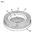
- Fig. 1 is a perspective view of a lamp device according to an embodiment of the present invention.
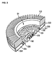
- Fig. 2 is a perspective view of a cross section of the lamp device according to the embodiment shown in Fig. 1 of the present invention.
- Fig. 3 is an exploded perspective view of a lamp device according to the embodiment shown in Fig. 1 of the present invention.
- a lamp device 100 includes a heat radiating body 110, a substrate 130, a light source unit 150, a light guider 170, a flange 190, a first member 210, a condensing lens 220, a second member 230 and a fixing member 250.
- the heat radiating body 110 is formed by organically coupling a ring structure 111, a plurality of fins 113 and a flat portion 115, so that the heat radiating body 110 has a shape of a donut.
- the shape of the heat radiating body 110 is not limited to this.
- the heat radiating body 110 may have a polygonal shape or other various shapes.
- the ring structure 111 has an inner surface and an outer surface such that an opening G1 having a central axis "A" is formed in the center of the ring structure 111.
- a plurality of the fins 113 are joined to the outer surface of the ring structure 111 and radially extend to the outside from the outer surface of the ring structure 111.
- a plurality of the fins 113 may be separated from each other at a regular interval such that heat generated from a light source unit 150 which will be described below is wholly uniformly radiated to the outside.
- the flat portion 115 is joined to one end of the outer surface of the ring structure 111 and extends perpendicular to the outer surface of the ring structure 111.
- the flat portion 115 is joined to one ends of a plurality of the fins 113 joined to the outer surface of the ring structure 111.
- the substrate 130 includes a top surface and a bottom surface.
- the top surface comes in surface contact with the flat portion 115 of the heat radiating body.
- the light source unit 150 is disposed on the bottom surface. It is desirable that a commonly used metal printed circuit board (PCB) is mainly used as the substrate 130. However, any substrate capable of including the light source unit can be used as the substrate 130.
- PCB metal printed circuit board
- the substrate 130 has a disk shape for sealing the ring structure 111 having the opening G1.
- the substrate 130 is required to have an opening G2 in the center thereof in order that heat generated from the light source unit 150 can be radiated to the outside through the circulation of the air.
- the opening G2 at the center of the substrate is placed corresponding to the opening G1 of the heat radiating body such that they have the same central axis "A".
- the light source unit 150 includes a plurality of light emitting diodes (LEDs).
- LEDs light emitting diodes
- a plurality of the LEDs are radially disposed on the bottom surface of the substrate. That is, a plurality of the LEDs may be disposed on the bottom surface of the substrate 130 at a regular interval just like a plurality of the fins 113 are disposed.
- the radiation area of heat generated from the operation of the LEDs becomes greater, so that heat release efficiency is improved.
- the heat from the LEDs is radiated through the surface contact between the flat portion of the heat radiating body and the top surface of the substrate and through a plurality of the fins of the heat radiating body, As a result, heat radiating surface area is increased so that a heat transfer characteristic is improved.
- a conductive sheet for radiating heat is further added between the substrate 130 and the flat portion 115 of the heat radiating body 110, so that it is possible to enhance the heat transfer characteristic between the substrate 130 and the heat radiating body 110.
- the light guider 170 includes a plurality of optical fibers. One end of each optical fiber is optically connected to a plurality of the LEDs 150.
- the optical fiber is taken as an example of the light guider 170, any device like a prism of an optical device capable of changing the direction of light generated by the light source unit into a desired direction can be used as the light guider 170.
- the flange 190 includes a plurality of holes 191 for inserting and binding the ends of a plurality of the optical fibers, and has an entire shape of a disk. Therefore, a plurality of the LEDs are bound by the flange 190, so that a wide emission area of light generated from a plurality of the radially disposed LEDs becomes smaller. As a result, the light is collected in a particular direction.
- the ends of the optical fibers inserted into the holes 191 of the flange 190 are aligned with the holes 191 of the flange such that the ends are placed on the same plane. This intends to obtain the uniform intensity of light at a particular plane on which the light is incident.
- the flange is seated in an opening G3 of the first member 210 which will be described below, so that the flange has an optical orientation plane according to the adjustment of the angle of the first member 210.
- the first member 210 includes a first projection 212, a second projection 213 and a first ring structure 211 having an inner surface and an outer surface such that a circular opening G3 having a central axis is formed in the center of the first ring structure 211.
- the first projection 212 and the second projection 213 are formed on the outer surface of the first ring structure 211 to face each other.
- the first projection 212 and the second projection 213 extend from the outer surface of the first ring structure 211 to the outside.
- the first projection 212 and the second projection 213 of the first member 210 are inserted into a first hole 231a and a second hole 231b of the second member 230, which are described below, respectively. Accordingly, the first member 210 is joined and fixed to the second member 230.
- the first member 210 is inclined at an angle to rotate about the first projection 212 and the second projection 213. Therefore, light generated from the light source unit 150 can be directed to a direction that a user desires by through adjustment of the angle of the first member 210.
- the condensing lens 220 is optically joined to the first member 210 and covers the opening opposite to the first member's circular opening in which the flange 190 is seated. Such a condensing lens more optically condenses the light which has been physically condensed by the flange.
- the second member 230 includes a first projection 232, a second projection 233 and a second ring structure 231 having an inner surface and an outer surface such that a circular opening G4 having a central axis is formed in the center of the second ring structure 231.
- the second member 230 includes the first hole 231a and the second hole 231b into which the first and the second projections 212 and 213 of the first member 210 are inserted.
- the first hole 231a and the second hole 231b penetrate the inner and outer surfaces of the second ring structure 231 and face each other.
- the first and the second projections 232 and 233 extend from the outer surface of the second ring structure 231 to the outside.
- a first imaginary line horizontally extending from the first projection 232 to the second projection 233 is at a right angle to a second imaginary line extending from the central axis of the first hole 231a to the central axis of the second hole 231b.
- the circumferential extent of the inner surface of the second member 230 is greater than that of the outer surface of the first member 210, so that the first member 210 is inserted into the second member 230.
- the fixing member 250 includes an inner circumferential portion 251 such that a circular opening G5 having a central axis of the inner circumferential portion 251 is formed, an outer circumferential portion 253 formed along the inner circumferential portion at a regular interval from the inner circumferential portion 251, and flat portion 255 extending vertically from the end of the inner circumferential portion to the end of the outer circumferential portion.
- the inner circumferential portion 251 of the fixing member 250 includes mutually facing first and second holes 251a and 251b into which the first projection 232 and the second projection 233 are inserted.
- the first projection 232 and the second projection 233 of the second member 230 are respectively inserted into the first hole 251a and the second hole 251b of the fixing member 250.
- the second member 230 is joined and fixed to inner surface of the inner circumferential portion 251 of the fixing member 250.
- the outer circumferential portion 253 of the fixing member 250 surrounds the light source unit 150 and the light guider 170.
- the lamp device mentioned above includes a heat radiating body having a structure in which the heat generated from the light emitting diodes can be radiated spatially not in an up-and-down direction but in a horizontal direction when the lamp device is operated, the entire volume of the lamp device can be actually reduced. Accordingly, as compared with a conventional heat radiating body radiating heat in the up-and-down direction, the heat radiating body of the present invention has a lower spatial limitation when the lamp device is installed. As a result, installation flexibility can be improved.
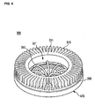
- Fig. 4 is a perspective view of another lamp device according to an embodiment of the present invention.
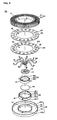
- Fig. 5 is an exploded perspective view of the lamp device according to the embodiment shown in Fig. 4 of the present invention.
- another lamp device 300 includes a heat radiating body 310, a heat radiating plate 330, a substrate 350, a light source unit 370, a light guider 390, a flange 410, a first member 430, a second member 450 and a fixing member 470.
- the heat radiating body 310 is formed by organically coupling a ring structure 311 and a plurality of fins 313, so that the heat radiating body 310 has a shape of a donut.
- the shape of the heat radiating body 310 is not limited to this.
- the structure 311 may have a polygonal shape or other various shapes.
- the ring structure 311 has an inner surface and an outer surface such that an opening G1' having a central axis "A" is formed in the center of the ring structure 311.
- a plurality of the fins 313 which are joined to the outer surface of the ring structure 311 and radially extend to the outside from the outer surface of the ring structure 311.
- a plurality of the fins 313 are separated from each other at a regular interval such that heat generated from a light source unit 370 which will be described below is wholly uniformly radiated to the outside. That is, two adjacent fins may be spaced apart from each other at a regular interval.
- the heat radiating plate 330 includes a hole 331 located at an area corresponding to the interval between the two adjacent fins among a plurality of the fins 313, and contacts with a plurality of the radially disposed fins 313.
- the heat radiating plate 330 also includes a central opening G2' placed corresponding to the central opening G1' of the heat radiating body 310.
- the hole 331 of the heat radiating plate 330 has a rectangular shape which is actually parallel with the longitudinal direction of the fin such that the external air more easily flows in from the top of the heat radiating body. When the substrate directly contacts with a plurality of the fins of the heat radiating body, the heat radiating plate 330 may be omitted.
- the heat radiating plate 330 is integrally formed with the heat radiating body 310, the heat radiating body 110 shown in Fig. 3 can be actually formed. In other words, the heat radiating plate 330 is able to function as the flat portion 115 of the heat radiating body 110 shown in Fig. 3 .
- the substrate 350 includes a top surface and a bottom surface.
- the top surface comes in surface contact with the heat radiating plate 330.
- the light source unit 370 is disposed on the bottom surface. It is desirable that a commonly used metal printed circuit board (PCB) is mainly used as the substrate 350. However, any substrate capable of including the light source unit can be used as the substrate 350.
- PCB metal printed circuit board
- the substrate 350 has a disk shape for sealing the heat radiating plate 330 having the opening G2'.
- the substrate 350 is required to have an opening G3' in the center thereof in order that heat generated from the light source unit 370 can be radiated to the outside through the circulation of the external air.
- the opening G3' at the center of the substrate 350 is placed corresponding to the opening G2' of the heat radiating plate 330.
- the substrate 350 includes a plurality of holes 351. A plurality of the holes 351 are placed between the light source units 370 which will be disposed on the bottom surface of the substrate.
- the holes of the substrate are disposed between the light source units 370 and correspond to the holes 331 of the heat radiating plate 330.
- the hole 351 of the substrate has also a rectangular shape.
- the substrate 350 is able to directly contact with a plurality of the fins of the heat radiating body and transfer heat without the heat radiating plate. It is possible to improve the heat transfer characteristic between the heat radiating body and the heat radiating plate or between the heat radiating plate and the substrate by adding a conductive sheet between the heat radiating body and the heat radiating plate or between the heat radiating plate and the substrate.
- the light source unit 370 includes a plurality of light emitting diodes (LEDs).
- a plurality of the LEDs are radially disposed on the bottom surface of the substrate. That is, a plurality of the LEDs are disposed on the bottom surface of the substrate 350 just like a plurality of the fins 313 of the heat radiating body 310 are disposed.
- the radiation area of heat generated from the operation of the LEDs becomes greater, so that heat release efficiency is improved.
- the heat from the LEDs can be radiated by the circulation of the air through the holes of either the substrate or the heat radiating plate.
- a plurality of the fins of the heat radiating body increase the heat radiation surface area, so that a heat transfer characteristic is improved.
- a conductive sheet for radiating heat is further added between the substrate and the heat radiating plate, so that it is possible to enhance the heat transfer characteristic between the substrate and the heat radiating plate.
- the light guider 390, the flange 410, the first member 430, a condensing lens 440, the second member 450 and the fixing member 470 are similar to those of the one embodiment of the present invention, the descriptions thereof will be omitted.
Landscapes
- Engineering & Computer Science (AREA)
- General Engineering & Computer Science (AREA)
- Physics & Mathematics (AREA)
- General Physics & Mathematics (AREA)
- Optics & Photonics (AREA)
- Arrangement Of Elements, Cooling, Sealing, Or The Like Of Lighting Devices (AREA)
- Non-Portable Lighting Devices Or Systems Thereof (AREA)
- Fastening Of Light Sources Or Lamp Holders (AREA)
Claims (15)
- Dispositif de lampe, comprenant :un corps dissipateur de chaleur (310) comprenant une structure (311) et une pluralité d'ailettes (313), dans lequel la structure (311) comprend une surface intérieure et une surface extérieure de sorte qu'une ouverture (G1') soit formée et dans lequel une pluralité des ailettes (313) s'étendent vers l'extérieur à partir de la surface extérieure de la structure (311) ; etun substrat (350) sous la pluralité des ailettes (313) du corps dissipateur de chaleur (310) et comprenant une pluralité de dispositifs luminescents (370) disposés sur un premier côté de celui-ci,caractérisé en ce que le dispositif de lampe comprend en outre une pluralité de fibres optiques (390) dont une extrémité est optiquement connectée respectivement à un dispositif luminescent de la pluralité de dispositifs luminescents (370).
- Dispositif de lampe selon la revendication 1, dans lequel le substrat (350) comprend une ouverture (G3') formée de sorte que l'ouverture (G3') corresponde à l'ouverture (G1') du corps dissipateur de chaleur (310).
- Dispositif de lampe selon la revendication 2, dans lequel l'ouverture (G1') du corps dissipateur de chaleur (310) et l'ouverture (G3') du substrat (350) possèdent le même axe central.
- Dispositif de lampe selon la revendication 1, dans lequel la structure (311) présente une forme annulaire.
- Dispositif de lampe selon la revendication 1, comprenant en outre une plaque dissipatrice de chaleur (330) située entre le substrat (350) et la pluralité des ailettes (313) du corps dissipateur de chaleur (310), et comportant une ouverture (G2') correspondant à l'ouverture du corps dissipateur de chaleur (310), dans lequel la plaque dissipatrice de chaleur (330) entre en contact de surface avec le substrat (350).
- Dispositif de lampe selon la revendication 5, dans lequel deux ailettes adjacentes parmi la pluralité des ailettes (313) du corps dissipateur de chaleur (310) sont espacées l'une de l'autre d'un intervalle prédéterminé, dans lequel la plaque dissipatrice de chaleur (330) comprend un trou (331) situé dans une zone correspondant à l'intervalle entre les deux ailettes (313), et dans lequel un côté de la plaque dissipatrice de chaleur (330) entre en contact avec une pluralité des ailettes.
- Dispositif de lampe selon la revendication 1, dans lequel les autres extrémités de la pluralité des fibres optiques (390) sont liées les unes aux autres.
- Dispositif de lampe selon la revendication 1, dans lequel la pluralité des ailettes (313) du corps dissipateur de chaleur (310) sont séparées les unes des autres d'un intervalle régulier.
- Dispositif de lampe selon la revendication 1 ou la revendication 5, dans lequel la pluralité des ailettes (313) du corps dissipateur de chaleur (310) entrent directement en contact avec un côté du substrat (350).
- Dispositif de lampe selon la revendication 1, dans lequel une pluralité des dispositifs luminescents (370) sont radialement disposés sur un côté du substrat (350).
- Dispositif de lampe selon la revendication 1 ou la revendication 10, dans lequel la pluralité des dispositifs luminescents (370) sont disposés à un intervalle régulier sur un côté du substrat (350).
- Dispositif de lampe selon la revendication 1, comprenant en outre une bride (410) comportant une pluralité de trous (411) pour insérer et lier les extrémités de la pluralité des fibres optiques (390).
- Dispositif de lampe selon la revendication 12, comprenant en outre un premier élément (430) comprenant une première structure annulaire (431) comportant une surface intérieure et une surface extérieure telles à former une ouverture circulaire (G4') et des saillies (432, 433) s'étendant à partir de la première structure annulaire (431),
dans lequel la bride (410) est assise dans l'ouverture (G4') du premier élément (430), et dans lequel la première structure annulaire (431) est en rotation par rapport aux saillies (432, 433). - Dispositif de lampe selon la revendication 13, comprenant en outre un second élément (450) comprenant une seconde structure annulaire (451), des saillies (452, 453) et des trous (451a, 451b),
dans lequel la seconde structure annulaire (451) comporte une surface intérieure et une surface extérieure telles à former une ouverture circulaire (G5'),
dans lequel les saillies (452, 453) s'étendent à partir de la seconde structure annulaire (451), et
dans lequel les trous (451a, 451b) sont insérés dans les saillies (432, 433) du premier élément (430). - Dispositif de lampe selon la revendication 14, dans lequel une première ligne imaginaire s'étendant horizontalement à partir des saillies (452, 453) du second élément (450) est à angle droit par rapport à une seconde ligne imaginaire s'étendant à partir des trous (451a, 451b).
Applications Claiming Priority (2)
| Application Number | Priority Date | Filing Date | Title |
|---|---|---|---|
| KR1020100091547A KR101742678B1 (ko) | 2010-09-17 | 2010-09-17 | 램프 장치 |
| EP11153747A EP2431660B1 (fr) | 2010-09-17 | 2011-02-08 | Dispositif de lampe |
Related Parent Applications (1)
| Application Number | Title | Priority Date | Filing Date |
|---|---|---|---|
| EP11153747A Division EP2431660B1 (fr) | 2010-09-17 | 2011-02-08 | Dispositif de lampe |
Publications (2)
| Publication Number | Publication Date |
|---|---|
| EP2511606A1 EP2511606A1 (fr) | 2012-10-17 |
| EP2511606B1 true EP2511606B1 (fr) | 2014-01-15 |
Family
ID=43929048
Family Applications (2)
| Application Number | Title | Priority Date | Filing Date |
|---|---|---|---|
| EP12176009.4A Active EP2511606B1 (fr) | 2010-09-17 | 2011-02-08 | Dispositif de lampe |
| EP11153747A Active EP2431660B1 (fr) | 2010-09-17 | 2011-02-08 | Dispositif de lampe |
Family Applications After (1)
| Application Number | Title | Priority Date | Filing Date |
|---|---|---|---|
| EP11153747A Active EP2431660B1 (fr) | 2010-09-17 | 2011-02-08 | Dispositif de lampe |
Country Status (5)
| Country | Link |
|---|---|
| US (1) | US8476813B2 (fr) |
| EP (2) | EP2511606B1 (fr) |
| JP (2) | JP5868622B2 (fr) |
| KR (1) | KR101742678B1 (fr) |
| CN (1) | CN102410515B (fr) |
Families Citing this family (6)
| Publication number | Priority date | Publication date | Assignee | Title |
|---|---|---|---|---|
| USD671257S1 (en) * | 2010-04-10 | 2012-11-20 | Lg Innotek Co., Ltd. | LED lamp |
| US8297790B2 (en) * | 2010-08-18 | 2012-10-30 | Lg Innotek Co., Ltd. | Lamp device |
| KR101742678B1 (ko) | 2010-09-17 | 2017-06-01 | 엘지이노텍 주식회사 | 램프 장치 |
| CN102606950B (zh) * | 2012-03-02 | 2013-11-27 | 中山伟强科技有限公司 | 一种led投射灯 |
| CN103411186A (zh) * | 2013-08-10 | 2013-11-27 | 无锡市宝成塑胶科技有限公司 | Led面板灯导热树脂灯座 |
| JP6931716B2 (ja) | 2017-04-21 | 2021-09-08 | ケーエムダブリュ・インコーポレーテッド | Mimoアンテナ装置 |
Family Cites Families (23)
| Publication number | Priority date | Publication date | Assignee | Title |
|---|---|---|---|---|
| JPH11202164A (ja) * | 1998-01-19 | 1999-07-30 | Toyoda Gosei Co Ltd | 光源モジュール |
| JP3066834U (ja) * | 1999-08-23 | 2000-03-07 | 株式会社遠藤照明 | 灯体ユニット交換タイプの天井埋込灯 |
| US6371628B1 (en) * | 2000-02-03 | 2002-04-16 | Lucifer Lighting Company | Post-installation adjustable lighting fixture |
| JP2002367406A (ja) | 2001-06-05 | 2002-12-20 | Algol:Kk | リング状led照明装置 |
| DE10256365A1 (de) * | 2001-12-04 | 2003-07-17 | Ccs Inc | Lichtabstrahlungsvorrichtung, Lichtquellenvorrichtung, Beleuchtungseinheit und Lichtverbindungsmechanismus |
| JP3966845B2 (ja) * | 2003-09-29 | 2007-08-29 | 株式会社松村電機製作所 | Led照明装置 |
| KR20060115911A (ko) * | 2003-12-02 | 2006-11-10 | 쓰리엠 이노베이티브 프로퍼티즈 컴파니 | 조사 장치 |
| US7329887B2 (en) * | 2003-12-02 | 2008-02-12 | 3M Innovative Properties Company | Solid state light device |
| US7258474B2 (en) * | 2005-04-21 | 2007-08-21 | Magna International Inc. | Headlamp with beam patterns formed from semiconductor light sources |
| JP4492458B2 (ja) * | 2005-06-22 | 2010-06-30 | パナソニック電工株式会社 | 照明器具 |
| US7431475B2 (en) * | 2005-07-22 | 2008-10-07 | Sony Corporation | Radiator for light emitting unit, and backlight device |
| US7588359B2 (en) * | 2005-09-26 | 2009-09-15 | Osram Sylvania Inc. | LED lamp with direct optical coupling in axial arrangement |
| US8789962B2 (en) * | 2005-10-27 | 2014-07-29 | Vikon Surgical, Llc | Surgical headlight |
| US7663229B2 (en) * | 2006-07-12 | 2010-02-16 | Hong Kong Applied Science And Technology Research Institute Co., Ltd. | Lighting device |
| CN201028412Y (zh) * | 2006-12-29 | 2008-02-27 | 梁立人 | 一种转头灯 |
| JPWO2009044716A1 (ja) * | 2007-10-01 | 2011-02-10 | 株式会社光波 | 発光装置 |
| US7458706B1 (en) * | 2007-11-28 | 2008-12-02 | Fu Zhun Precision Industry (Shen Zhen) Co., Ltd. | LED lamp with a heat sink |
| JP2009140718A (ja) * | 2007-12-05 | 2009-06-25 | Toshiba Lighting & Technology Corp | 照明装置 |
| US7682049B2 (en) | 2008-04-15 | 2010-03-23 | Fu Zhun Precision Industry (Shen Zhen) Co., Ltd. | LED lamp |
| JP2010108792A (ja) * | 2008-10-30 | 2010-05-13 | Toshiba Lighting & Technology Corp | 照明器具 |
| IT1392500B1 (it) * | 2008-12-30 | 2012-03-09 | I B T S P A | Dispositivo di illuminazione a led a dissipazione di calore ottimizzata per esterni e grandi aree coperte |
| DE102009008096B4 (de) * | 2009-02-09 | 2016-10-27 | Osram Gmbh | Kühlkörper für eine Leuchtvorrichtung |
| KR101742678B1 (ko) | 2010-09-17 | 2017-06-01 | 엘지이노텍 주식회사 | 램프 장치 |
-
2010
- 2010-09-17 KR KR1020100091547A patent/KR101742678B1/ko active IP Right Grant
-
2011
- 2011-02-08 EP EP12176009.4A patent/EP2511606B1/fr active Active
- 2011-02-08 EP EP11153747A patent/EP2431660B1/fr active Active
- 2011-03-04 US US13/040,779 patent/US8476813B2/en active Active
- 2011-03-22 CN CN201110072437.2A patent/CN102410515B/zh active Active
- 2011-07-08 JP JP2011151734A patent/JP5868622B2/ja active Active
-
2016
- 2016-01-06 JP JP2016001095A patent/JP6196330B2/ja active Active
Also Published As
| Publication number | Publication date |
|---|---|
| EP2431660B1 (fr) | 2012-11-07 |
| JP5868622B2 (ja) | 2016-02-24 |
| EP2431660A1 (fr) | 2012-03-21 |
| EP2511606A1 (fr) | 2012-10-17 |
| CN102410515B (zh) | 2014-06-11 |
| JP6196330B2 (ja) | 2017-09-13 |
| KR20120029632A (ko) | 2012-03-27 |
| CN102410515A (zh) | 2012-04-11 |
| US20110204764A1 (en) | 2011-08-25 |
| JP2012064562A (ja) | 2012-03-29 |
| JP2016042492A (ja) | 2016-03-31 |
| KR101742678B1 (ko) | 2017-06-01 |
| US8476813B2 (en) | 2013-07-02 |
Similar Documents
| Publication | Publication Date | Title |
|---|---|---|
| EP2420720B1 (fr) | Dispositif de lampe | |
| US8083375B2 (en) | Lamp device | |
| EP2511606B1 (fr) | Dispositif de lampe | |
| JP5284522B1 (ja) | 光半導体照明装置 | |
| US10571084B2 (en) | Lighting module, and lighting apparatus having same | |
| CN101614367B (zh) | 发光二极管灯具 | |
| JP2014072194A (ja) | 放熱モジュール及び放熱モジュールを有する組合せ型の照明装置 | |
| KR101055053B1 (ko) | 조명 장치 | |
| KR101929256B1 (ko) | 조명 장치 | |
| KR101733465B1 (ko) | Led 조명등의 방열구조 | |
| KR101742679B1 (ko) | 램프 장치 | |
| JP2013020734A (ja) | 屋外用照明器具 | |
| KR101761384B1 (ko) | 램프 장치 | |
| KR101752421B1 (ko) | 램프 장치 | |
| KR101860039B1 (ko) | 조명 장치 | |
| KR101800387B1 (ko) | Led 등기구 | |
| KR20140103459A (ko) | 조명장치 | |
| KR20110005131U (ko) | 조립 및 메인터넌스 특성이 향상된 엘이디 램프 | |
| KR20170124381A (ko) | 엘이디 조명장치 | |
| KR20110011330A (ko) | 조명 장치 |
Legal Events
| Date | Code | Title | Description |
|---|---|---|---|
| PUAI | Public reference made under article 153(3) epc to a published international application that has entered the european phase |
Free format text: ORIGINAL CODE: 0009012 |
|
| AC | Divisional application: reference to earlier application |
Ref document number: 2431660 Country of ref document: EP Kind code of ref document: P |
|
| AK | Designated contracting states |
Kind code of ref document: A1 Designated state(s): AL AT BE BG CH CY CZ DE DK EE ES FI FR GB GR HR HU IE IS IT LI LT LU LV MC MK MT NL NO PL PT RO RS SE SI SK SM TR |
|
| RIN1 | Information on inventor provided before grant (corrected) |
Inventor name: KONG, KYUNG-IL |
|
| 17P | Request for examination filed |
Effective date: 20130412 |
|
| GRAP | Despatch of communication of intention to grant a patent |
Free format text: ORIGINAL CODE: EPIDOSNIGR1 |
|
| INTG | Intention to grant announced |
Effective date: 20130523 |
|
| GRAS | Grant fee paid |
Free format text: ORIGINAL CODE: EPIDOSNIGR3 |
|
| GRAP | Despatch of communication of intention to grant a patent |
Free format text: ORIGINAL CODE: EPIDOSNIGR1 |
|
| INTG | Intention to grant announced |
Effective date: 20131007 |
|
| GRAA | (expected) grant |
Free format text: ORIGINAL CODE: 0009210 |
|
| AC | Divisional application: reference to earlier application |
Ref document number: 2431660 Country of ref document: EP Kind code of ref document: P |
|
| AK | Designated contracting states |
Kind code of ref document: B1 Designated state(s): AL AT BE BG CH CY CZ DE DK EE ES FI FR GB GR HR HU IE IS IT LI LT LU LV MC MK MT NL NO PL PT RO RS SE SI SK SM TR |
|
| REG | Reference to a national code |
Ref country code: CH Ref legal event code: EP Ref country code: GB Ref legal event code: FG4D |
|
| REG | Reference to a national code |
Ref country code: AT Ref legal event code: REF Ref document number: 650008 Country of ref document: AT Kind code of ref document: T Effective date: 20140215 |
|
| REG | Reference to a national code |
Ref country code: IE Ref legal event code: FG4D |
|
| REG | Reference to a national code |
Ref country code: DE Ref legal event code: R096 Ref document number: 602011004745 Country of ref document: DE Effective date: 20140227 |
|
| REG | Reference to a national code |
Ref country code: NL Ref legal event code: T3 |
|
| REG | Reference to a national code |
Ref country code: AT Ref legal event code: MK05 Ref document number: 650008 Country of ref document: AT Kind code of ref document: T Effective date: 20140115 |
|
| REG | Reference to a national code |
Ref country code: LT Ref legal event code: MG4D |
|
| PG25 | Lapsed in a contracting state [announced via postgrant information from national office to epo] |
Ref country code: IS Free format text: LAPSE BECAUSE OF FAILURE TO SUBMIT A TRANSLATION OF THE DESCRIPTION OR TO PAY THE FEE WITHIN THE PRESCRIBED TIME-LIMIT Effective date: 20140515 Ref country code: NO Free format text: LAPSE BECAUSE OF FAILURE TO SUBMIT A TRANSLATION OF THE DESCRIPTION OR TO PAY THE FEE WITHIN THE PRESCRIBED TIME-LIMIT Effective date: 20140415 Ref country code: LT Free format text: LAPSE BECAUSE OF FAILURE TO SUBMIT A TRANSLATION OF THE DESCRIPTION OR TO PAY THE FEE WITHIN THE PRESCRIBED TIME-LIMIT Effective date: 20140115 |
|
| PG25 | Lapsed in a contracting state [announced via postgrant information from national office to epo] |
Ref country code: SE Free format text: LAPSE BECAUSE OF FAILURE TO SUBMIT A TRANSLATION OF THE DESCRIPTION OR TO PAY THE FEE WITHIN THE PRESCRIBED TIME-LIMIT Effective date: 20140115 Ref country code: ES Free format text: LAPSE BECAUSE OF FAILURE TO SUBMIT A TRANSLATION OF THE DESCRIPTION OR TO PAY THE FEE WITHIN THE PRESCRIBED TIME-LIMIT Effective date: 20140115 Ref country code: PT Free format text: LAPSE BECAUSE OF FAILURE TO SUBMIT A TRANSLATION OF THE DESCRIPTION OR TO PAY THE FEE WITHIN THE PRESCRIBED TIME-LIMIT Effective date: 20140515 Ref country code: FI Free format text: LAPSE BECAUSE OF FAILURE TO SUBMIT A TRANSLATION OF THE DESCRIPTION OR TO PAY THE FEE WITHIN THE PRESCRIBED TIME-LIMIT Effective date: 20140115 Ref country code: AT Free format text: LAPSE BECAUSE OF FAILURE TO SUBMIT A TRANSLATION OF THE DESCRIPTION OR TO PAY THE FEE WITHIN THE PRESCRIBED TIME-LIMIT Effective date: 20140115 Ref country code: CY Free format text: LAPSE BECAUSE OF FAILURE TO SUBMIT A TRANSLATION OF THE DESCRIPTION OR TO PAY THE FEE WITHIN THE PRESCRIBED TIME-LIMIT Effective date: 20140115 |
|
| PG25 | Lapsed in a contracting state [announced via postgrant information from national office to epo] |
Ref country code: RS Free format text: LAPSE BECAUSE OF FAILURE TO SUBMIT A TRANSLATION OF THE DESCRIPTION OR TO PAY THE FEE WITHIN THE PRESCRIBED TIME-LIMIT Effective date: 20140115 Ref country code: LV Free format text: LAPSE BECAUSE OF FAILURE TO SUBMIT A TRANSLATION OF THE DESCRIPTION OR TO PAY THE FEE WITHIN THE PRESCRIBED TIME-LIMIT Effective date: 20140115 Ref country code: BE Free format text: LAPSE BECAUSE OF FAILURE TO SUBMIT A TRANSLATION OF THE DESCRIPTION OR TO PAY THE FEE WITHIN THE PRESCRIBED TIME-LIMIT Effective date: 20140115 Ref country code: HR Free format text: LAPSE BECAUSE OF FAILURE TO SUBMIT A TRANSLATION OF THE DESCRIPTION OR TO PAY THE FEE WITHIN THE PRESCRIBED TIME-LIMIT Effective date: 20140115 |
|
| REG | Reference to a national code |
Ref country code: CH Ref legal event code: PL |
|
| REG | Reference to a national code |
Ref country code: DE Ref legal event code: R097 Ref document number: 602011004745 Country of ref document: DE |
|
| PG25 | Lapsed in a contracting state [announced via postgrant information from national office to epo] |
Ref country code: CZ Free format text: LAPSE BECAUSE OF FAILURE TO SUBMIT A TRANSLATION OF THE DESCRIPTION OR TO PAY THE FEE WITHIN THE PRESCRIBED TIME-LIMIT Effective date: 20140115 Ref country code: RO Free format text: LAPSE BECAUSE OF FAILURE TO SUBMIT A TRANSLATION OF THE DESCRIPTION OR TO PAY THE FEE WITHIN THE PRESCRIBED TIME-LIMIT Effective date: 20140115 Ref country code: CH Free format text: LAPSE BECAUSE OF NON-PAYMENT OF DUE FEES Effective date: 20140228 Ref country code: EE Free format text: LAPSE BECAUSE OF FAILURE TO SUBMIT A TRANSLATION OF THE DESCRIPTION OR TO PAY THE FEE WITHIN THE PRESCRIBED TIME-LIMIT Effective date: 20140115 Ref country code: LI Free format text: LAPSE BECAUSE OF NON-PAYMENT OF DUE FEES Effective date: 20140228 Ref country code: MC Free format text: LAPSE BECAUSE OF FAILURE TO SUBMIT A TRANSLATION OF THE DESCRIPTION OR TO PAY THE FEE WITHIN THE PRESCRIBED TIME-LIMIT Effective date: 20140115 Ref country code: DK Free format text: LAPSE BECAUSE OF FAILURE TO SUBMIT A TRANSLATION OF THE DESCRIPTION OR TO PAY THE FEE WITHIN THE PRESCRIBED TIME-LIMIT Effective date: 20140115 |
|
| PLBE | No opposition filed within time limit |
Free format text: ORIGINAL CODE: 0009261 |
|
| STAA | Information on the status of an ep patent application or granted ep patent |
Free format text: STATUS: NO OPPOSITION FILED WITHIN TIME LIMIT |
|
| PG25 | Lapsed in a contracting state [announced via postgrant information from national office to epo] |
Ref country code: SK Free format text: LAPSE BECAUSE OF FAILURE TO SUBMIT A TRANSLATION OF THE DESCRIPTION OR TO PAY THE FEE WITHIN THE PRESCRIBED TIME-LIMIT Effective date: 20140115 Ref country code: PL Free format text: LAPSE BECAUSE OF FAILURE TO SUBMIT A TRANSLATION OF THE DESCRIPTION OR TO PAY THE FEE WITHIN THE PRESCRIBED TIME-LIMIT Effective date: 20140115 |
|
| REG | Reference to a national code |
Ref country code: IE Ref legal event code: MM4A |
|
| 26N | No opposition filed |
Effective date: 20141016 |
|
| REG | Reference to a national code |
Ref country code: FR Ref legal event code: PLFP Year of fee payment: 5 |
|
| PG25 | Lapsed in a contracting state [announced via postgrant information from national office to epo] |
Ref country code: IE Free format text: LAPSE BECAUSE OF NON-PAYMENT OF DUE FEES Effective date: 20140208 |
|
| REG | Reference to a national code |
Ref country code: DE Ref legal event code: R097 Ref document number: 602011004745 Country of ref document: DE Effective date: 20141016 |
|
| PG25 | Lapsed in a contracting state [announced via postgrant information from national office to epo] |
Ref country code: SI Free format text: LAPSE BECAUSE OF FAILURE TO SUBMIT A TRANSLATION OF THE DESCRIPTION OR TO PAY THE FEE WITHIN THE PRESCRIBED TIME-LIMIT Effective date: 20140115 |
|
| REG | Reference to a national code |
Ref country code: FR Ref legal event code: PLFP Year of fee payment: 6 |
|
| PG25 | Lapsed in a contracting state [announced via postgrant information from national office to epo] |
Ref country code: MT Free format text: LAPSE BECAUSE OF FAILURE TO SUBMIT A TRANSLATION OF THE DESCRIPTION OR TO PAY THE FEE WITHIN THE PRESCRIBED TIME-LIMIT Effective date: 20140115 |
|
| PG25 | Lapsed in a contracting state [announced via postgrant information from national office to epo] |
Ref country code: SM Free format text: LAPSE BECAUSE OF FAILURE TO SUBMIT A TRANSLATION OF THE DESCRIPTION OR TO PAY THE FEE WITHIN THE PRESCRIBED TIME-LIMIT Effective date: 20140115 |
|
| PG25 | Lapsed in a contracting state [announced via postgrant information from national office to epo] |
Ref country code: BG Free format text: LAPSE BECAUSE OF FAILURE TO SUBMIT A TRANSLATION OF THE DESCRIPTION OR TO PAY THE FEE WITHIN THE PRESCRIBED TIME-LIMIT Effective date: 20140115 Ref country code: GR Free format text: LAPSE BECAUSE OF FAILURE TO SUBMIT A TRANSLATION OF THE DESCRIPTION OR TO PAY THE FEE WITHIN THE PRESCRIBED TIME-LIMIT Effective date: 20140416 Ref country code: IT Free format text: LAPSE BECAUSE OF FAILURE TO SUBMIT A TRANSLATION OF THE DESCRIPTION OR TO PAY THE FEE WITHIN THE PRESCRIBED TIME-LIMIT Effective date: 20140115 |
|
| PG25 | Lapsed in a contracting state [announced via postgrant information from national office to epo] |
Ref country code: HU Free format text: LAPSE BECAUSE OF FAILURE TO SUBMIT A TRANSLATION OF THE DESCRIPTION OR TO PAY THE FEE WITHIN THE PRESCRIBED TIME-LIMIT; INVALID AB INITIO Effective date: 20110208 Ref country code: TR Free format text: LAPSE BECAUSE OF FAILURE TO SUBMIT A TRANSLATION OF THE DESCRIPTION OR TO PAY THE FEE WITHIN THE PRESCRIBED TIME-LIMIT Effective date: 20140115 Ref country code: LU Free format text: LAPSE BECAUSE OF NON-PAYMENT OF DUE FEES Effective date: 20140208 |
|
| REG | Reference to a national code |
Ref country code: FR Ref legal event code: PLFP Year of fee payment: 7 |
|
| REG | Reference to a national code |
Ref country code: FR Ref legal event code: PLFP Year of fee payment: 8 |
|
| PGFP | Annual fee paid to national office [announced via postgrant information from national office to epo] |
Ref country code: NL Payment date: 20180108 Year of fee payment: 8 |
|
| PG25 | Lapsed in a contracting state [announced via postgrant information from national office to epo] |
Ref country code: MK Free format text: LAPSE BECAUSE OF FAILURE TO SUBMIT A TRANSLATION OF THE DESCRIPTION OR TO PAY THE FEE WITHIN THE PRESCRIBED TIME-LIMIT Effective date: 20140115 |
|
| PG25 | Lapsed in a contracting state [announced via postgrant information from national office to epo] |
Ref country code: AL Free format text: LAPSE BECAUSE OF FAILURE TO SUBMIT A TRANSLATION OF THE DESCRIPTION OR TO PAY THE FEE WITHIN THE PRESCRIBED TIME-LIMIT Effective date: 20140115 |
|
| REG | Reference to a national code |
Ref country code: NL Ref legal event code: MM Effective date: 20190301 |
|
| PG25 | Lapsed in a contracting state [announced via postgrant information from national office to epo] |
Ref country code: NL Free format text: LAPSE BECAUSE OF NON-PAYMENT OF DUE FEES Effective date: 20190301 |
|
| REG | Reference to a national code |
Ref country code: GB Ref legal event code: 732E Free format text: REGISTERED BETWEEN 20210722 AND 20210728 |
|
| REG | Reference to a national code |
Ref country code: DE Ref legal event code: R081 Ref document number: 602011004745 Country of ref document: DE Owner name: SUZHOU LEKIN SEMICONDUCTOR CO. LTD., TAICANG, CN Free format text: FORMER OWNER: LG INNOTEK CO., LTD., SEOUL, KR |
|
| PGFP | Annual fee paid to national office [announced via postgrant information from national office to epo] |
Ref country code: FR Payment date: 20230110 Year of fee payment: 13 |
|
| PGFP | Annual fee paid to national office [announced via postgrant information from national office to epo] |
Ref country code: GB Payment date: 20230105 Year of fee payment: 13 Ref country code: DE Payment date: 20230104 Year of fee payment: 13 |