EP2511047A2 - Clamping apparatus - Google Patents
Clamping apparatus Download PDFInfo
- Publication number
- EP2511047A2 EP2511047A2 EP12163697A EP12163697A EP2511047A2 EP 2511047 A2 EP2511047 A2 EP 2511047A2 EP 12163697 A EP12163697 A EP 12163697A EP 12163697 A EP12163697 A EP 12163697A EP 2511047 A2 EP2511047 A2 EP 2511047A2
- Authority
- EP
- European Patent Office
- Prior art keywords
- shaft
- clamping apparatus
- axis
- guide
- rotation
- Prior art date
- Legal status (The legal status is an assumption and is not a legal conclusion. Google has not performed a legal analysis and makes no representation as to the accuracy of the status listed.)
- Withdrawn
Links
Images


Classifications
-
- B—PERFORMING OPERATIONS; TRANSPORTING
- B25—HAND TOOLS; PORTABLE POWER-DRIVEN TOOLS; MANIPULATORS
- B25B—TOOLS OR BENCH DEVICES NOT OTHERWISE PROVIDED FOR, FOR FASTENING, CONNECTING, DISENGAGING OR HOLDING
- B25B5/00—Clamps
- B25B5/06—Arrangements for positively actuating jaws
- B25B5/12—Arrangements for positively actuating jaws using toggle links
- B25B5/122—Arrangements for positively actuating jaws using toggle links with fluid drive
-
- B—PERFORMING OPERATIONS; TRANSPORTING
- B25—HAND TOOLS; PORTABLE POWER-DRIVEN TOOLS; MANIPULATORS
- B25B—TOOLS OR BENCH DEVICES NOT OTHERWISE PROVIDED FOR, FOR FASTENING, CONNECTING, DISENGAGING OR HOLDING
- B25B5/00—Clamps
- B25B5/06—Arrangements for positively actuating jaws
- B25B5/08—Arrangements for positively actuating jaws using cams
- B25B5/087—Arrangements for positively actuating jaws using cams actuated by a hydraulic or pneumatic piston
Definitions
- the disclosure relates to a clamping apparatus and, more particularly, to a shaft mounted in a housing so that it is displaceable perpendicular to its axis of rotation in a guide element, connected to the drive mechanism, to implement a rotational and translational movement to the clamp actuating element.
- DE 10 2004 007 465 A1 illustrates a clamping apparatus. It discloses a shaft that is mounted in a housing element. The shaft can be rotated about an axis of rotation (pivot axis). The shaft, on the one hand, is connected to a drive mechanism disposed in the housing element and, on the other hand, is connected to an actuating element (in particular a clamping tool with clamping arm) in a torsion-proof manner.
- the drive mechanism in one case, includes a so-called toggle lever mechanism ( Figure 3 ) and in the other case a curved guide ( Figure 4 ).
- the clamping apparatuses are used, for example, in automobile manufacture to firmly clamp parts to be welded together.
- a clamping apparatus that comprises a shaft mounted in a housing element.
- the shaft is rotated about an axis of rotation.
- One end of the shaft is connected to a drive mechanism.
- the drive mechanism is disposed in the housing element.
- the other end of the shaft is connected to an actuating element in a torsion-proof manner.
- the shaft implements a rotational and translational movement to the actuating element.
- the shaft is mounted so that it can be displaced perpendicular to the axis of rotation.
- the shaft is positioned in a guide element that is connected to the drive mechanism.
- the guide element is rotatably mounted in the housing element.
- the shaft which implements a rotational and translational movement of the actuating element, is mounted so that it can be displaced perpendicular to the axis of rotation in a guide element.
- the guide element is connected to the drive mechanism.
- the drive mechanism is rotatably mounted in the housing element.
- rotary or rotational movement of the shaft can be superposed with a displacement or translational movement.
- This additional degree of freedom has an advantage that it is possible to initially bring, for example, the clamping arm to the workpiece or towards the workpiece with a simple pivoting movement.
- the translational movement carries out or concludes the clamping process.
- Figure 1 is a sectional view of a first embodiment of the clamping apparatus according to the disclosure in a locked clamping position.
- Figure 2 is a sectional view of the clamping apparatus according to Figure 1 in an unlocked clamping position.
- Figure 3 is a sectional view of the clamping apparatus according to Figure 1 in an open position.
- Figure 4 is a partly dismounted perspective view of the clamping apparatus according to Figure 1 in a locked clamping position.
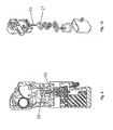
- Figure 5 is an exploded perspective view of the clamping apparatus according to Figure 1 in a clamping position.
- Figure 6 is a sectional view of the clamping apparatus according to Figure 1 in a locked clamping position (without the shaft) (in a different sectional plane compared to Figure 1 ).
- Figure 7 is a sectional view of the clamping apparatus according to Figure 1 in an intermediate position.
- Figure 8 is a sectional view of the clamping apparatus according to Figure 1 in an open position.
- Figure 9 is a sectional view of a second embodiment of the clamping apparatus according to the disclosure with an electrical drive.
- Figure 10 is an exploded view on the drive side of the clamping apparatus according to Figure 9 .
- the clamping apparatus shown in Figures 1 to 10 include a shaft 2 rotatably mounted in a housing element 1 about an axis of rotation. One end of the shaft is connected to a drive mechanism 3 disposed in the housing element 1. The other end is connected to an actuating element 4 or clamping element, in a torsion-proof manner.
- the drive mechanism 3 is optionally configured as a manual drive (not shown additionally), a pneumatic or hydraulic piston drive (See Figures 1 to 8 ) and/or an electrical rotary drive (see Figures 9 and 10 ).
- the shaft 2 which implements a rotational and a translational movement of the actuating element 4, is mounted so that it can be displaced perpendicularly to the axis of rotation in a guide element.
- the guide element is connected to the drive mechanism 3.
- the guide mechanism 3 is mounted rotatably in the housing element 1.
- the displacement movement typically covers a range of a few millimeters whereas the pivoting range is at least 90°, preferably up to at least 150°.
- the axis of rotation always moves together with the shaft 2 (parallel displacement).
- the housing element 1 is formed from two housing shells, 19, 20 as seen in Figure 5 .
- the housing shells 19, 20 receive the guide element 5 between them.
- the housing element 1 or the housing shells 19, 20 have an access opening 21 for the guide element 5.
- the opening 21 further has a cylindrical inner wall on the guide element side.
- the guide element 5 has at least one partially cylindrical outer wall 22 on the through opening side (see Figure 4 ).
- the guide element 5 has a through opening for the shaft 2 (see Figure 6 ).
- the through opening 6 is configured as a positive connection to the shaft 2.
- the shaft 2 (as shown in the figures) is configured to have a square cross-section.
- the through opening is configured to have a rectangular cross-section (approximately). This additionally has the result that all positions of the axis of rotation of the shaft 2 are arranged to run parallel to one another.
- the drive mechanism 3 is connected to the actuating element 4.
- a lever arm 7, oriented perpendicular to the axis of rotation, is disposed on the shaft 2.
- a guide member 8 is disposed on the lever arm 7.
- the guide member 8 faces away from the shaft.
- a guide track 9 is disposed on the housing element 1 or on the housing shells 19, 20 to receive the guide member 8.
- the track 9 includes a first radially variable and a second radially constant guide region 10, 11 in relation to the axis of rotation, as seen in Figure 3 .
- the guide member 8 can be located at radially different positions with respect to the axis of rotation.
- the second section 11 it can only move about the axis of rotation on a (fixed) circumferential path.
- the guide element 5 is provided with a lever arm 12 oriented perpendicular to the axis of rotation.
- a lug 13 is disposed between the lever arm 7 on the shaft side and the lever arm 12 on the guide element side.
- the lug 13 is connected on the shaft side, at one end of the lever arm 7. On the other end it is connected to the lever arm 12, on the guide element side, in an articulated manner.
- the guide member 8 is disposed on one side and the tab 13 is disposed on another side of the lever arm 7 of the shaft 2.
- the guide element 5 is provided with a gear wheel or at least with one gear wheel section 14 surrounding the guide element.
- the gear wheel section 14 is connected to the lever arm 12 in a torsionally rigid manner.
- the gear wheel section 14 is mounted together with the lever arm 12 so that it can be rotated on the guide element 5. Furthermore, an axis of rotation of the gear wheel section 14 is configured to run parallel to the axis of rotation of the shaft 2.
- the guide element 5 is in principle, formed from two circular segments that extend depthwise.
- the shaft 2 is located between the two segments.
- the structural cohesion is obtained through the lever arm 12 and the gear wheel section 14.
- Each has a correspondingly large circular through opening.
- the shaft 2 is displaceable between the two circular-segment-shaped parts of the guide element 5 (parallel to the axis of rotation). The exact position will be determined by the guide member 8, running in the guide track 9, and the lug 13 connected both to the lever arm 7 and to the lever arm 12.
- the gear wheel section 14 or the gear wheel is configured to cooperate with a tooth segment 15 to transmit a torque to the shaft 2.
- the tooth segment 15 is rotatably mounted in the housing element 1.
- the tooth segment 15 is preferably configured in a triangular or slice-of-cake shape.
- the tooth segment 15 is connected at its pointed end (apex), via a rotary joint 22, to the housing element 1 or the housing shells 19, 20.
- a pivot lever 16 is disposed in the housing element 1.
- the pivot lever 16 can be pivoted about a pivot axis 17.
- the pivot axis 17 is located parallel to the axis of rotation.
- a lug 18 is arranged in an articulated manner on a region of the pivot lever 16 remote from the pivot axis.
- the lug 18 is connected, with its end remote from the pivot lever in an articulated manner, to the tooth segment 15.
- the lug 18, connected to the pivot lever 16, is disposed in an articulated manner on the tooth segment 15 at a distance from the rotary joint 22 of the tooth segment 15.
- the pivot axis 17 is either connected to a hand lever (accessible from outside) (not shown) or the pivot lever 16 is provided with a slit-shaped engagement region 23.
- a guide member 25, disposed on a piston rod 24 of a piston drive is configured to engage in the engagement region 23.
- a guide member 25, disposed (not co-rotating) on a rotary spindle 26 of an electrical rotary drive is configured to engage in this engagement region 23.
- the rotary spindle 26 is connected to the electrical rotary drive, via a belt drive 27.
- the housing element 1 has a head region 28.
- the head region 28 receives the guide element 5.
- a connecting region 29 receives the pivot lever 16.
- the connecting region 29 is preferably configured to be enclosed by two half-shell-shaped connecting parts 30 provided with hole patterns as required.
- toggle lever mechanism includes an intermediate member and a linear adjusting member.
- the intermediate member is connected to the lever arm 12, on the guide element side, in an articulated manner.
- Figure 3 shows the open position of the clamping apparatus.
- the piston rod 24 is now moved upwards by the piston drive. This has a result of the guide member 25 moving inside the engagement region 23.
- the pivot lever 16 is rotated at the same time in a counterclockwise direction about the pivot axis 17.
- a force is transferred, via the lug 18, to the tooth segment 15.
- the tooth segment 15 begins to turn in a clockwise direction about its rotary joint 22.
- the tooth segment 15 is positively engaged in the gear wheel section 14 or is meshed with it.
- the gear wheel section 14 together with the lever arm 12 on the guide element side is rotated in a counterclockwise direction.
- the second exemplary embodiment shown in Figures 9 and 10 functions identically with regard to the connection between pivot lever 16 and shaft 2.
- the only difference is the drive of the guide member 25.
- it is disposed on the upper end of an axially adjustable rotary spindle 26.
- the spindle 26 is connected, via a belt drive 27, to an electrical rotary drive.
Abstract
Description
- The disclosure relates to a clamping apparatus and, more particularly, to a shaft mounted in a housing so that it is displaceable perpendicular to its axis of rotation in a guide element, connected to the drive mechanism, to implement a rotational and translational movement to the clamp actuating element.
-
DE 10 2004 007 465 A1 illustrates a clamping apparatus. It discloses a shaft that is mounted in a housing element. The shaft can be rotated about an axis of rotation (pivot axis). The shaft, on the one hand, is connected to a drive mechanism disposed in the housing element and, on the other hand, is connected to an actuating element (in particular a clamping tool with clamping arm) in a torsion-proof manner. In particular, with reference toFigures 3 and4 ofDE 10 2004 007 465 A1Figure 3 ) and in the other case a curved guide (Figure 4 ). - The clamping apparatuses are used, for example, in automobile manufacture to firmly clamp parts to be welded together.
- It is the object of the disclosure to improve a clamping apparatus of the above type.
- The object is achieved by a clamping apparatus that comprises a shaft mounted in a housing element. The shaft is rotated about an axis of rotation. One end of the shaft is connected to a drive mechanism. The drive mechanism is disposed in the housing element. The other end of the shaft is connected to an actuating element in a torsion-proof manner. The shaft implements a rotational and translational movement to the actuating element. The shaft is mounted so that it can be displaced perpendicular to the axis of rotation. The shaft is positioned in a guide element that is connected to the drive mechanism. The guide element is rotatably mounted in the housing element.
- According to the disclosure, the shaft, which implements a rotational and translational movement of the actuating element, is mounted so that it can be displaced perpendicular to the axis of rotation in a guide element. The guide element is connected to the drive mechanism. The drive mechanism is rotatably mounted in the housing element.
- Further, according to the disclosure, rotary or rotational movement of the shaft can be superposed with a displacement or translational movement. This additional degree of freedom has an advantage that it is possible to initially bring, for example, the clamping arm to the workpiece or towards the workpiece with a simple pivoting movement. The translational movement carries out or concludes the clamping process.
- This increased technical effort has the advantage that the actuating element can be placed parallel onto the workpiece. The result is that edge imprints, which increasingly occur during purely rotative movement of the actuating element, can be avoided. This aspect takes into account the requirement to provide as little excess material as possible at the parts to be welded. The result is that clamping points are increasingly positioned on surfaces that are subsequently visible. It follows that imprints of the actuating element cannot specifically remain at these points.
- Further areas of applicability will become apparent from the description provided herein. The description and specific examples in this summary are intended for purposes of illustration only and are not intended to limit the scope of the present disclosure.
- The clamping apparatus according to the invention including its advantageous further developments according to the dependent patent claims will be explained in detail hereinafter with reference to the diagrammatic representation of two exemplary embodiments.
- The drawings described herein are for illustrative purposes only of selected embodiments and not all possible implementations, and are not intended to limit the scope of the present disclosure.
-
Figure 1 is a sectional view of a first embodiment of the clamping apparatus according to the disclosure in a locked clamping position. -
Figure 2 is a sectional view of the clamping apparatus according toFigure 1 in an unlocked clamping position. -
Figure 3 is a sectional view of the clamping apparatus according toFigure 1 in an open position. -
Figure 4 is a partly dismounted perspective view of the clamping apparatus according toFigure 1 in a locked clamping position. -
Figure 5 is an exploded perspective view of the clamping apparatus according toFigure 1 in a clamping position. -
Figure 6 is a sectional view of the clamping apparatus according toFigure 1 in a locked clamping position (without the shaft) (in a different sectional plane compared toFigure 1 ). -
Figure 7 is a sectional view of the clamping apparatus according toFigure 1 in an intermediate position. -
Figure 8 is a sectional view of the clamping apparatus according toFigure 1 in an open position. -
Figure 9 is a sectional view of a second embodiment of the clamping apparatus according to the disclosure with an electrical drive. -
Figure 10 is an exploded view on the drive side of the clamping apparatus according toFigure 9 . - The clamping apparatus shown in
Figures 1 to 10 include ashaft 2 rotatably mounted in a housing element 1 about an axis of rotation. One end of the shaft is connected to a drive mechanism 3 disposed in the housing element 1. The other end is connected to an actuating element 4 or clamping element, in a torsion-proof manner. The drive mechanism 3 is optionally configured as a manual drive (not shown additionally), a pneumatic or hydraulic piston drive (SeeFigures 1 to 8 ) and/or an electrical rotary drive (seeFigures 9 and 10 ). - In all embodiments of the clamping apparatus according to the disclosure, the
shaft 2, which implements a rotational and a translational movement of the actuating element 4, is mounted so that it can be displaced perpendicularly to the axis of rotation in a guide element. The guide element is connected to the drive mechanism 3. The guide mechanism 3 is mounted rotatably in the housing element 1. - According to the disclosure, as already explained, and is also apparent from the figures, it is possible to pivot the actuating element or the clamping arm and to move it in a translational manner. Specifically, in particular, it moves towards the end of the clamping movement. Conversely, during the release initially a displacement movement and finally the pivoting movement takes place. This takes place, in particular, in order to avoid scratches or imprints on the workpiece during firm clamping.
- The displacement movement typically covers a range of a few millimeters whereas the pivoting range is at least 90°, preferably up to at least 150°. As is apparent from the figures, the axis of rotation always moves together with the shaft 2 (parallel displacement).
- In order to be able to simply mount the clamping apparatus, the housing element 1 is formed from two housing shells, 19, 20 as seen in
Figure 5 . Thehousing shells guide element 5 between them. At the same time, the housing element 1 or thehousing shells guide element 5. The opening 21 further has a cylindrical inner wall on the guide element side. Theguide element 5 has at least one partially cylindricalouter wall 22 on the through opening side (seeFigure 4 ). - The
guide element 5 has a through opening for the shaft 2 (seeFigure 6 ). The throughopening 6 is configured as a positive connection to theshaft 2. In this regard, the shaft 2 (as shown in the figures) is configured to have a square cross-section. The through opening is configured to have a rectangular cross-section (approximately). This additionally has the result that all positions of the axis of rotation of theshaft 2 are arranged to run parallel to one another. - According to the two exemplary embodiments shown in the figures, the drive mechanism 3 is connected to the actuating element 4. A
lever arm 7, oriented perpendicular to the axis of rotation, is disposed on theshaft 2. Aguide member 8 is disposed on thelever arm 7. Theguide member 8 faces away from the shaft. A guide track 9 is disposed on the housing element 1 or on thehousing shells guide member 8. The track 9 includes a first radially variable and a second radiallyconstant guide region Figure 3 . In thefirst section 10 theguide member 8 can be located at radially different positions with respect to the axis of rotation. In thesecond section 11 it can only move about the axis of rotation on a (fixed) circumferential path. - As a comparison shows, in the embodiment shown in the figures, some of the aforesaid components are present in duplicate. These were not mentioned explicitly in the description merely for the sake of clarity. This also applies to the following description.
- It is further provided that the
guide element 5 is provided with alever arm 12 oriented perpendicular to the axis of rotation. In addition, alug 13 is disposed between thelever arm 7 on the shaft side and thelever arm 12 on the guide element side. Thelug 13 is connected on the shaft side, at one end of thelever arm 7. On the other end it is connected to thelever arm 12, on the guide element side, in an articulated manner. In addition, theguide member 8 is disposed on one side and thetab 13 is disposed on another side of thelever arm 7 of theshaft 2. - The
guide element 5 is provided with a gear wheel or at least with onegear wheel section 14 surrounding the guide element. Thegear wheel section 14 is connected to thelever arm 12 in a torsionally rigid manner. Thegear wheel section 14 is mounted together with thelever arm 12 so that it can be rotated on theguide element 5. Furthermore, an axis of rotation of thegear wheel section 14 is configured to run parallel to the axis of rotation of theshaft 2. - As is deduced from the figures, the
guide element 5 is in principle, formed from two circular segments that extend depthwise. Theshaft 2 is located between the two segments. The structural cohesion is obtained through thelever arm 12 and thegear wheel section 14. Each has a correspondingly large circular through opening. Theshaft 2 is displaceable between the two circular-segment-shaped parts of the guide element 5 (parallel to the axis of rotation). The exact position will be determined by theguide member 8, running in the guide track 9, and thelug 13 connected both to thelever arm 7 and to thelever arm 12. - The
gear wheel section 14 or the gear wheel is configured to cooperate with atooth segment 15 to transmit a torque to theshaft 2. Thetooth segment 15 is rotatably mounted in the housing element 1. Thetooth segment 15 is preferably configured in a triangular or slice-of-cake shape. Thetooth segment 15 is connected at its pointed end (apex), via a rotary joint 22, to the housing element 1 or thehousing shells - A
pivot lever 16 is disposed in the housing element 1. Thepivot lever 16 can be pivoted about apivot axis 17. Thepivot axis 17 is located parallel to the axis of rotation. Alug 18 is arranged in an articulated manner on a region of thepivot lever 16 remote from the pivot axis. Thelug 18 is connected, with its end remote from the pivot lever in an articulated manner, to thetooth segment 15. Thelug 18, connected to thepivot lever 16, is disposed in an articulated manner on thetooth segment 15 at a distance from the rotary joint 22 of thetooth segment 15. - In order to be able to transmit an (adjusting) force to the
pivot lever 16, thepivot axis 17 is either connected to a hand lever (accessible from outside) (not shown) or thepivot lever 16 is provided with a slit-shapedengagement region 23. In the exemplary embodiment according toFigures 1 to 8 , aguide member 25, disposed on apiston rod 24 of a piston drive, is configured to engage in theengagement region 23. In the exemplary embodiment according toFigures 9 and 10 , aguide member 25, disposed (not co-rotating) on arotary spindle 26 of an electrical rotary drive, is configured to engage in thisengagement region 23. Therotary spindle 26 is connected to the electrical rotary drive, via abelt drive 27. - With reference to
Figure 5 , the housing element 1 has ahead region 28. Thehead region 28 receives theguide element 5. A connectingregion 29 receives thepivot lever 16. The connectingregion 29 is preferably configured to be enclosed by two half-shell-shaped connectingparts 30 provided with hole patterns as required. - Alternatively to the two exemplary embodiments with gear wheels or rotary spindles shown in
Figures 1 to 8 or9 and 10 , it is also possible to use a toggle lever mechanism. The toggle lever mechanism includes an intermediate member and a linear adjusting member. In this case, the intermediate member is connected to thelever arm 12, on the guide element side, in an articulated manner. - The functioning of the two exemplary embodiments will be briefly explained.
- The starting point for the first exemplary embodiment is
Figure 3. Figure 3 shows the open position of the clamping apparatus. Thepiston rod 24 is now moved upwards by the piston drive. This has a result of theguide member 25 moving inside theengagement region 23. As this occurs, thepivot lever 16 is rotated at the same time in a counterclockwise direction about thepivot axis 17. In addition, a force is transferred, via thelug 18, to thetooth segment 15. Thetooth segment 15 begins to turn in a clockwise direction about its rotary joint 22. Additionally, thetooth segment 15 is positively engaged in thegear wheel section 14 or is meshed with it. Thegear wheel section 14 together with thelever arm 12 on the guide element side is rotated in a counterclockwise direction. This rotary movement is also transferred, via thelug 13, to the shaft-side lever arm 7. The displacement position on thelever arm 7 inside theguide element 5 is at the same time fixed by means of theguide member 8 guided in the guide track 9.Figure 2 shows an intermediate position where the actuating element 4 is no longer being pivoted, however, the final clamping position is not yet reached. The final position is shown inFigure 1 . Also, it follows, at the same time, that the actuating element 4 is locked in the clamping position by the rectilinear arrangement of thelever arms lug 13, with respect to one another (as in an over center toggle lever arrangement). - The second exemplary embodiment shown in
Figures 9 and 10 functions identically with regard to the connection betweenpivot lever 16 andshaft 2. The only difference is the drive of theguide member 25. In this case, it is disposed on the upper end of an axially adjustablerotary spindle 26. Thespindle 26 is connected, via abelt drive 27, to an electrical rotary drive. - The description of the disclosure is merely exemplary in nature and thus, variations that do not depart from the gist of the disclosure are intended to be within the scope of the disclosure. Such variations are not to be regarded as a departure from the spirit and scope of the disclosure.
Claims (15)
- A clamping apparatus comprising:a shaft mounted in a housing element, the shaft is rotated about an axis of rotation, one end of the shaft is connected to a drive mechanism, the drive mechanism is disposed in the housing element, the other end of the shaft is connected to an actuating element in a torsion-proof manner; the shaft implements a rotational and translational movement to an actuating element, the shaft is mounted so that it can be displaced perpendicular to the axis of rotation in a guide element connected to the drive mechanism, the guide element is mounted rotatably in the housing element.
- The clamping apparatus according to claim 1, where the guide element has a through opening for the shaft
- The clamping apparatus according to claim 2, wherein the through opening is configured as a positive connection to the shaft.
- The clamping apparatus according to claim 2, wherein the shaft has a square configuration in cross-section and the through opening has a rectangular configuration in cross-section.
- The clamping apparatus according claims 1, wherein a lever arm is oriented perpendicular to the axis of rotation and is disposed on the shaft.
- The clamping apparatus according to claim 5, further comprising a guide member disposed on the lever arm facing away from the shaft.
- The clamping apparatus according to claim 6, further comprising a guide track, for the guide member, disposed on the housing element.
- The clamping apparatus according to claim 7, wherein the guide track comprises a first radially variable and a second radially constant guide region in relation to the axis of rotation.
- The clamping apparatus according to claims 1, further comprising a lever arm, oriented perpendicular to the axis of rotation, disposed on the guide element.
- The clamping apparatus according to claim 9, further comprising a lug disposed between the lever arm, on the shaft side, and the lever arm, on the guide element side.
- The clamping apparatus according to claim 10, wherein the lug, in an articulated manner, is connected at one end to the lever arm on the shaft side and on the other end to the lever arm on the guide element side.
- The clamping apparatus according to claim 1, wherein the guide element is provided with at least one gear wheel section.
- The clamping apparatus according to claim 12, wherein the gear wheel section is configured to cooperate with a tooth segment rotatably mounted in the housing element.
- The clamping apparatus according to claim 1, further comprising a pivot lever disposed in the housing element, the pivot lever can be pivoted about a pivot axis located parallel to the axis of rotation.
- The clamping apparatus according to claim 14, further comprising a lug, arranged in an articulated manner, on a region of the pivot lever remote from the pivot axis, the lug is connected with its end remote from the pivot lever in an articulated manner to the tooth segment.
Applications Claiming Priority (1)
| Application Number | Priority Date | Filing Date | Title |
|---|---|---|---|
| US13/086,651 US8382083B2 (en) | 2011-04-14 | 2011-04-14 | Clamping apparatus |
Publications (2)
| Publication Number | Publication Date |
|---|---|
| EP2511047A2 true EP2511047A2 (en) | 2012-10-17 |
| EP2511047A3 EP2511047A3 (en) | 2016-08-17 |
Family
ID=45976766
Family Applications (1)
| Application Number | Title | Priority Date | Filing Date |
|---|---|---|---|
| EP12163697.1A Withdrawn EP2511047A3 (en) | 2011-04-14 | 2012-04-11 | Clamping apparatus |
Country Status (6)
| Country | Link |
|---|---|
| US (1) | US8382083B2 (en) |
| EP (1) | EP2511047A3 (en) |
| CN (1) | CN102729172B (en) |
| BR (1) | BR102012008968A2 (en) |
| CA (1) | CA2772900A1 (en) |
| MX (1) | MX2012004213A (en) |
Cited By (3)
| Publication number | Priority date | Publication date | Assignee | Title |
|---|---|---|---|---|
| WO2016019947A1 (en) * | 2014-08-08 | 2016-02-11 | De-Sta-Co Europe Gmbh | Clamping device |
| WO2018210398A1 (en) * | 2017-05-15 | 2018-11-22 | Olaf Und André Tünkers Gbr | Toggle clamp device for use in vehicle body manufacturing in the automotive industry |
| DE102021000171B3 (en) | 2021-01-15 | 2021-12-30 | Olaf und André Tünkers GbR (vertretungsberechtigter Gesellschafter: Dipl.-Ing. Olaf Tünkers, 40883 Ratingen) | Toggle clamping device with straight clamping force and spindle drive |
Families Citing this family (3)
| Publication number | Priority date | Publication date | Assignee | Title |
|---|---|---|---|---|
| US10625382B2 (en) | 2012-08-01 | 2020-04-21 | Delaware Capital Formation, Inc. | Toggle lever clamp |
| CN105234617B (en) * | 2015-11-17 | 2016-11-16 | 安徽江淮汽车股份有限公司 | A kind of synchronous turnover mechanism |
| CN112123594A (en) * | 2020-09-23 | 2020-12-25 | 衡阳市衡山科学城科技创新服务有限公司 | Be applied to ceramic dielectric filter CNC processingequipment of 5G technique |
Citations (1)
| Publication number | Priority date | Publication date | Assignee | Title |
|---|---|---|---|---|
| DE102004007465A1 (en) | 2004-02-13 | 2005-09-01 | De-Sta-Co Metallerzeugnisse Gmbh | driving device |
Family Cites Families (14)
| Publication number | Priority date | Publication date | Assignee | Title |
|---|---|---|---|---|
| DE19644832A1 (en) * | 1996-10-29 | 1998-04-30 | Karlheinz Menkhoff | Pneumatic adjustable spanner |
| JP3683447B2 (en) * | 1999-10-15 | 2005-08-17 | Smc株式会社 | Clamping device |
| US6557841B2 (en) * | 2001-06-26 | 2003-05-06 | Norgren Automotive, Inc. | Over-center power clamp toggle mechanism |
| TW487617B (en) * | 2000-08-04 | 2002-05-21 | Smc Kk | Clamp apparatus |
| JP3602433B2 (en) * | 2000-11-27 | 2004-12-15 | Smc株式会社 | Clamping device |
| ITMI20021756A1 (en) * | 2002-08-02 | 2004-02-03 | Luciano Migliori | HOOKING DEVICE FOR WORKPIECES. |
| JP2004090163A (en) * | 2002-08-30 | 2004-03-25 | Smc Corp | Clamper |
| US8132799B2 (en) * | 2004-04-02 | 2012-03-13 | Phd, Inc. | Pin clamp accessories |
| US7182326B2 (en) * | 2004-04-02 | 2007-02-27 | Phd, Inc. | Pin clamp |
| JP4789006B2 (en) * | 2006-07-31 | 2011-10-05 | Smc株式会社 | Clamping device |
| WO2008089145A2 (en) * | 2007-01-15 | 2008-07-24 | Phd, Inc. | Armover clamp assembly |
| JP4892668B2 (en) * | 2007-02-15 | 2012-03-07 | Smc株式会社 | Clamping device |
| US20080237957A1 (en) * | 2007-03-27 | 2008-10-02 | Conrad Earl Waldorf | Adjustable stroke gripper |
| ES2707249T3 (en) * | 2007-06-19 | 2019-04-03 | Phd Inc | Pin clamp set |
-
2011
- 2011-04-14 US US13/086,651 patent/US8382083B2/en not_active Expired - Fee Related
-
2012
- 2012-03-29 CA CA2772900A patent/CA2772900A1/en not_active Abandoned
- 2012-04-10 MX MX2012004213A patent/MX2012004213A/en active IP Right Grant
- 2012-04-11 EP EP12163697.1A patent/EP2511047A3/en not_active Withdrawn
- 2012-04-13 CN CN201210164087.7A patent/CN102729172B/en not_active Expired - Fee Related
- 2012-04-16 BR BRBR102012008968-8A patent/BR102012008968A2/en not_active IP Right Cessation
Patent Citations (1)
| Publication number | Priority date | Publication date | Assignee | Title |
|---|---|---|---|---|
| DE102004007465A1 (en) | 2004-02-13 | 2005-09-01 | De-Sta-Co Metallerzeugnisse Gmbh | driving device |
Cited By (5)
| Publication number | Priority date | Publication date | Assignee | Title |
|---|---|---|---|---|
| WO2016019947A1 (en) * | 2014-08-08 | 2016-02-11 | De-Sta-Co Europe Gmbh | Clamping device |
| US10328551B2 (en) | 2014-08-08 | 2019-06-25 | De-Sta-Co Europe Gmbh | Clamping device |
| WO2018210398A1 (en) * | 2017-05-15 | 2018-11-22 | Olaf Und André Tünkers Gbr | Toggle clamp device for use in vehicle body manufacturing in the automotive industry |
| DE102018002358B4 (en) * | 2017-05-15 | 2020-02-13 | Olaf Und André Tünkers Gbr (Vertretungsberechtigter Gesellschafter: Dipl.-Ing. Olaf Tünkers, 40885 Ratingen) | Toggle lever clamping device, for use in the body shop of the automotive industry with an additional abutment on the toggle joint element |
| DE102021000171B3 (en) | 2021-01-15 | 2021-12-30 | Olaf und André Tünkers GbR (vertretungsberechtigter Gesellschafter: Dipl.-Ing. Olaf Tünkers, 40883 Ratingen) | Toggle clamping device with straight clamping force and spindle drive |
Also Published As
| Publication number | Publication date |
|---|---|
| BR102012008968A2 (en) | 2013-06-04 |
| EP2511047A3 (en) | 2016-08-17 |
| MX2012004213A (en) | 2012-10-26 |
| CN102729172B (en) | 2015-08-19 |
| US20120263518A1 (en) | 2012-10-18 |
| US8382083B2 (en) | 2013-02-26 |
| CN102729172A (en) | 2012-10-17 |
| CA2772900A1 (en) | 2012-10-14 |
Similar Documents
| Publication | Publication Date | Title |
|---|---|---|
| EP2511047A2 (en) | Clamping apparatus | |
| EP2786817B1 (en) | Crimping machine system | |
| RU2600780C2 (en) | Electric clamp apparatus | |
| JP6559664B2 (en) | Turret for tool machine | |
| EP2727729B1 (en) | Printing cylinder asssembly for a printing machine | |
| JP2013237447A (en) | Hinge structure | |
| JP2019534165A5 (en) | ||
| CN112388348B (en) | Zero clamping device | |
| CN103930332A (en) | Fixing device for an adjustable steering column for a motor vehicle | |
| EP2479009A1 (en) | Swing device and articulated robot having same | |
| JP2017529826A5 (en) | ||
| US20180257693A1 (en) | Clamping device of an adjustable steering column for motor vehicles | |
| JP5975061B2 (en) | Caulking device and caulking method | |
| CN108367439A (en) | Revolute robot's arm | |
| CA2748874A1 (en) | Rotary position transducer array which compensates for radial play | |
| JP2014046365A (en) | Holder for coupler | |
| JP5690950B2 (en) | Mold with circular cam device | |
| US20180099348A1 (en) | Tip changer for spot welding machine | |
| CN103144609A (en) | Drive unit | |
| US20230211458A1 (en) | Surface processing device | |
| US20170122417A1 (en) | Drive device for driving a tool slide in a folding system | |
| JP2016104372A5 (en) | ||
| JP6099639B2 (en) | Seal unit for molding and sealing the open end of a tubular package container and method for adjusting the seal unit | |
| JP2018525236A (en) | Device for clamping parts to tools | |
| CN207257766U (en) | Turning machine |
Legal Events
| Date | Code | Title | Description |
|---|---|---|---|
| PUAI | Public reference made under article 153(3) epc to a published international application that has entered the european phase |
Free format text: ORIGINAL CODE: 0009012 |
|
| AK | Designated contracting states |
Kind code of ref document: A2 Designated state(s): AL AT BE BG CH CY CZ DE DK EE ES FI FR GB GR HR HU IE IS IT LI LT LU LV MC MK MT NL NO PL PT RO RS SE SI SK SM TR |
|
| AX | Request for extension of the european patent |
Extension state: BA ME |
|
| PUAL | Search report despatched |
Free format text: ORIGINAL CODE: 0009013 |
|
| AK | Designated contracting states |
Kind code of ref document: A3 Designated state(s): AL AT BE BG CH CY CZ DE DK EE ES FI FR GB GR HR HU IE IS IT LI LT LU LV MC MK MT NL NO PL PT RO RS SE SI SK SM TR |
|
| AX | Request for extension of the european patent |
Extension state: BA ME |
|
| RIC1 | Information provided on ipc code assigned before grant |
Ipc: B25B 5/08 20060101AFI20160712BHEP Ipc: B25B 5/12 20060101ALI20160712BHEP |
|
| STAA | Information on the status of an ep patent application or granted ep patent |
Free format text: STATUS: THE APPLICATION IS DEEMED TO BE WITHDRAWN |
|
| 18D | Application deemed to be withdrawn |
Effective date: 20170218 |