EP2511005A1 - Silica-containing hydrogen-separating material and process for production thereof, and hydrogen separation module and hydrogen production apparatus each comprises the hydrogen-separating material - Google Patents
Silica-containing hydrogen-separating material and process for production thereof, and hydrogen separation module and hydrogen production apparatus each comprises the hydrogen-separating material Download PDFInfo
- Publication number
- EP2511005A1 EP2511005A1 EP10836057A EP10836057A EP2511005A1 EP 2511005 A1 EP2511005 A1 EP 2511005A1 EP 10836057 A EP10836057 A EP 10836057A EP 10836057 A EP10836057 A EP 10836057A EP 2511005 A1 EP2511005 A1 EP 2511005A1
- Authority
- EP
- European Patent Office
- Prior art keywords
- silica glass
- hydrogen
- hydrogen separation
- porous
- separation material
- Prior art date
- Legal status (The legal status is an assumption and is not a legal conclusion. Google has not performed a legal analysis and makes no representation as to the accuracy of the status listed.)
- Granted
Links
Images

Classifications
-
- B—PERFORMING OPERATIONS; TRANSPORTING
- B01—PHYSICAL OR CHEMICAL PROCESSES OR APPARATUS IN GENERAL
- B01D—SEPARATION
- B01D71/00—Semi-permeable membranes for separation processes or apparatus characterised by the material; Manufacturing processes specially adapted therefor
- B01D71/02—Inorganic material
- B01D71/024—Oxides
- B01D71/027—Silicium oxide
-
- B—PERFORMING OPERATIONS; TRANSPORTING
- B01—PHYSICAL OR CHEMICAL PROCESSES OR APPARATUS IN GENERAL
- B01D—SEPARATION
- B01D53/00—Separation of gases or vapours; Recovering vapours of volatile solvents from gases; Chemical or biological purification of waste gases, e.g. engine exhaust gases, smoke, fumes, flue gases, aerosols
- B01D53/02—Separation of gases or vapours; Recovering vapours of volatile solvents from gases; Chemical or biological purification of waste gases, e.g. engine exhaust gases, smoke, fumes, flue gases, aerosols by adsorption, e.g. preparative gas chromatography
- B01D53/04—Separation of gases or vapours; Recovering vapours of volatile solvents from gases; Chemical or biological purification of waste gases, e.g. engine exhaust gases, smoke, fumes, flue gases, aerosols by adsorption, e.g. preparative gas chromatography with stationary adsorbents
- B01D53/047—Pressure swing adsorption
-
- B—PERFORMING OPERATIONS; TRANSPORTING
- B01—PHYSICAL OR CHEMICAL PROCESSES OR APPARATUS IN GENERAL
- B01D—SEPARATION
- B01D53/00—Separation of gases or vapours; Recovering vapours of volatile solvents from gases; Chemical or biological purification of waste gases, e.g. engine exhaust gases, smoke, fumes, flue gases, aerosols
- B01D53/22—Separation of gases or vapours; Recovering vapours of volatile solvents from gases; Chemical or biological purification of waste gases, e.g. engine exhaust gases, smoke, fumes, flue gases, aerosols by diffusion
- B01D53/228—Separation of gases or vapours; Recovering vapours of volatile solvents from gases; Chemical or biological purification of waste gases, e.g. engine exhaust gases, smoke, fumes, flue gases, aerosols by diffusion characterised by specific membranes
-
- B—PERFORMING OPERATIONS; TRANSPORTING
- B01—PHYSICAL OR CHEMICAL PROCESSES OR APPARATUS IN GENERAL
- B01D—SEPARATION
- B01D67/00—Processes specially adapted for manufacturing semi-permeable membranes for separation processes or apparatus
- B01D67/0039—Inorganic membrane manufacture
-
- B—PERFORMING OPERATIONS; TRANSPORTING
- B01—PHYSICAL OR CHEMICAL PROCESSES OR APPARATUS IN GENERAL
- B01D—SEPARATION
- B01D67/00—Processes specially adapted for manufacturing semi-permeable membranes for separation processes or apparatus
- B01D67/0039—Inorganic membrane manufacture
- B01D67/0041—Inorganic membrane manufacture by agglomeration of particles in the dry state
- B01D67/00415—Inorganic membrane manufacture by agglomeration of particles in the dry state by additive layer techniques, e.g. selective laser sintering [SLS], selective laser melting [SLM] or 3D printing
-
- B—PERFORMING OPERATIONS; TRANSPORTING
- B01—PHYSICAL OR CHEMICAL PROCESSES OR APPARATUS IN GENERAL
- B01D—SEPARATION
- B01D69/00—Semi-permeable membranes for separation processes or apparatus characterised by their form, structure or properties; Manufacturing processes specially adapted therefor
- B01D69/04—Tubular membranes
-
- B—PERFORMING OPERATIONS; TRANSPORTING
- B01—PHYSICAL OR CHEMICAL PROCESSES OR APPARATUS IN GENERAL
- B01D—SEPARATION
- B01D69/00—Semi-permeable membranes for separation processes or apparatus characterised by their form, structure or properties; Manufacturing processes specially adapted therefor
- B01D69/10—Supported membranes; Membrane supports
- B01D69/105—Support pretreatment
-
- B—PERFORMING OPERATIONS; TRANSPORTING
- B01—PHYSICAL OR CHEMICAL PROCESSES OR APPARATUS IN GENERAL
- B01D—SEPARATION
- B01D69/00—Semi-permeable membranes for separation processes or apparatus characterised by their form, structure or properties; Manufacturing processes specially adapted therefor
- B01D69/10—Supported membranes; Membrane supports
- B01D69/108—Inorganic support material
-
- B—PERFORMING OPERATIONS; TRANSPORTING
- B01—PHYSICAL OR CHEMICAL PROCESSES OR APPARATUS IN GENERAL
- B01D—SEPARATION
- B01D71/00—Semi-permeable membranes for separation processes or apparatus characterised by the material; Manufacturing processes specially adapted therefor
- B01D71/02—Inorganic material
- B01D71/024—Oxides
-
- B—PERFORMING OPERATIONS; TRANSPORTING
- B01—PHYSICAL OR CHEMICAL PROCESSES OR APPARATUS IN GENERAL
- B01D—SEPARATION
- B01D71/00—Semi-permeable membranes for separation processes or apparatus characterised by the material; Manufacturing processes specially adapted therefor
- B01D71/02—Inorganic material
- B01D71/04—Glass
-
- C—CHEMISTRY; METALLURGY
- C01—INORGANIC CHEMISTRY
- C01B—NON-METALLIC ELEMENTS; COMPOUNDS THEREOF; METALLOIDS OR COMPOUNDS THEREOF NOT COVERED BY SUBCLASS C01C
- C01B3/00—Hydrogen; Gaseous mixtures containing hydrogen; Separation of hydrogen from mixtures containing it; Purification of hydrogen; Reversible storage of hydrogen
- C01B3/02—Production of hydrogen; Production of gaseous mixtures containing hydrogen
- C01B3/32—Production of hydrogen; Production of gaseous mixtures containing hydrogen by reaction of gaseous or liquid organic compounds with gasifying agents, e.g. water, carbon dioxide or air
- C01B3/34—Production of hydrogen; Production of gaseous mixtures containing hydrogen by reaction of gaseous or liquid organic compounds with gasifying agents, e.g. water, carbon dioxide or air by reaction of hydrocarbons with gasifying agents
- C01B3/38—Production of hydrogen; Production of gaseous mixtures containing hydrogen by reaction of gaseous or liquid organic compounds with gasifying agents, e.g. water, carbon dioxide or air by reaction of hydrocarbons with gasifying agents using catalysts
-
- C—CHEMISTRY; METALLURGY
- C01—INORGANIC CHEMISTRY
- C01B—NON-METALLIC ELEMENTS; COMPOUNDS THEREOF; METALLOIDS OR COMPOUNDS THEREOF NOT COVERED BY SUBCLASS C01C
- C01B3/00—Hydrogen; Gaseous mixtures containing hydrogen; Separation of hydrogen from mixtures containing it; Purification of hydrogen; Reversible storage of hydrogen
- C01B3/50—Separation of hydrogen or hydrogen-containing gases from gaseous mixtures, e.g. purification
- C01B3/501—Separation of hydrogen or hydrogen-containing gases from gaseous mixtures, e.g. purification by diffusion
- C01B3/503—Separation of hydrogen or hydrogen-containing gases from gaseous mixtures, e.g. purification by diffusion characterised by membranes
-
- B—PERFORMING OPERATIONS; TRANSPORTING
- B01—PHYSICAL OR CHEMICAL PROCESSES OR APPARATUS IN GENERAL
- B01D—SEPARATION
- B01D2256/00—Main component in the product gas stream after treatment
- B01D2256/16—Hydrogen
-
- B—PERFORMING OPERATIONS; TRANSPORTING
- B01—PHYSICAL OR CHEMICAL PROCESSES OR APPARATUS IN GENERAL
- B01D—SEPARATION
- B01D2257/00—Components to be removed
- B01D2257/50—Carbon oxides
- B01D2257/502—Carbon monoxide
-
- B—PERFORMING OPERATIONS; TRANSPORTING
- B01—PHYSICAL OR CHEMICAL PROCESSES OR APPARATUS IN GENERAL
- B01D—SEPARATION
- B01D2311/00—Details relating to membrane separation process operations and control
- B01D2311/26—Further operations combined with membrane separation processes
- B01D2311/2626—Absorption or adsorption
-
- B—PERFORMING OPERATIONS; TRANSPORTING
- B01—PHYSICAL OR CHEMICAL PROCESSES OR APPARATUS IN GENERAL
- B01D—SEPARATION
- B01D2311/00—Details relating to membrane separation process operations and control
- B01D2311/26—Further operations combined with membrane separation processes
- B01D2311/2696—Catalytic reactions
-
- B—PERFORMING OPERATIONS; TRANSPORTING
- B01—PHYSICAL OR CHEMICAL PROCESSES OR APPARATUS IN GENERAL
- B01D—SEPARATION
- B01D2323/00—Details relating to membrane preparation
- B01D2323/15—Use of additives
- B01D2323/218—Additive materials
- B01D2323/2181—Inorganic additives
- B01D2323/21811—Metals
-
- B—PERFORMING OPERATIONS; TRANSPORTING
- B01—PHYSICAL OR CHEMICAL PROCESSES OR APPARATUS IN GENERAL
- B01D—SEPARATION
- B01D2325/00—Details relating to properties of membranes
- B01D2325/02—Details relating to pores or porosity of the membranes
-
- B—PERFORMING OPERATIONS; TRANSPORTING
- B01—PHYSICAL OR CHEMICAL PROCESSES OR APPARATUS IN GENERAL
- B01D—SEPARATION
- B01D2325/00—Details relating to properties of membranes
- B01D2325/04—Characteristic thickness
-
- B—PERFORMING OPERATIONS; TRANSPORTING
- B01—PHYSICAL OR CHEMICAL PROCESSES OR APPARATUS IN GENERAL
- B01D—SEPARATION
- B01D2325/00—Details relating to properties of membranes
- B01D2325/22—Thermal or heat-resistance properties
-
- C—CHEMISTRY; METALLURGY
- C01—INORGANIC CHEMISTRY
- C01B—NON-METALLIC ELEMENTS; COMPOUNDS THEREOF; METALLOIDS OR COMPOUNDS THEREOF NOT COVERED BY SUBCLASS C01C
- C01B2203/00—Integrated processes for the production of hydrogen or synthesis gas
- C01B2203/02—Processes for making hydrogen or synthesis gas
- C01B2203/0205—Processes for making hydrogen or synthesis gas containing a reforming step
- C01B2203/0227—Processes for making hydrogen or synthesis gas containing a reforming step containing a catalytic reforming step
- C01B2203/0233—Processes for making hydrogen or synthesis gas containing a reforming step containing a catalytic reforming step the reforming step being a steam reforming step
-
- C—CHEMISTRY; METALLURGY
- C01—INORGANIC CHEMISTRY
- C01B—NON-METALLIC ELEMENTS; COMPOUNDS THEREOF; METALLOIDS OR COMPOUNDS THEREOF NOT COVERED BY SUBCLASS C01C
- C01B2203/00—Integrated processes for the production of hydrogen or synthesis gas
- C01B2203/04—Integrated processes for the production of hydrogen or synthesis gas containing a purification step for the hydrogen or the synthesis gas
- C01B2203/0405—Purification by membrane separation
-
- C—CHEMISTRY; METALLURGY
- C01—INORGANIC CHEMISTRY
- C01B—NON-METALLIC ELEMENTS; COMPOUNDS THEREOF; METALLOIDS OR COMPOUNDS THEREOF NOT COVERED BY SUBCLASS C01C
- C01B2203/00—Integrated processes for the production of hydrogen or synthesis gas
- C01B2203/04—Integrated processes for the production of hydrogen or synthesis gas containing a purification step for the hydrogen or the synthesis gas
- C01B2203/0405—Purification by membrane separation
- C01B2203/041—In-situ membrane purification during hydrogen production
Definitions
- the present invention concerns a hydrogen separation material for separating hydrogen at high purity from a gas mixture containing hydrogen formed by fuel reforming, etc., as well as a hydrogen separation module and a hydrogen production apparatus having the same and, particularly, it relates to a hydrogen separation material in which a silica-based hydrogen permselective membrane for allowing hydrogen to permeable therethrough selectively is formed on the surface of a porous support and a manufacturing method therefor, as well as a hydrogen separation module and a hydrogen production apparatus having the same.
- a method of steam reforming a hydrocarbon fuel at a temperature of about 700°C (CH 4 + H 2 O ⁇ CO + 3H 2 ) and then performing further CO-shifting at about several hundred °C (CO + H 2 O ⁇ CO 2 + H 2 ) has been utilized generally with a view point of price competitive power.
- Ingredients of a gas obtained by way of the reactions described above include, in addition to hydrogen, carbon dioxide, carbon monoxide and, further, unreacted hydrocarbons and water.
- a method of taking out highly pure hydrogen from a hydrogen containing gas mixture includes, for example, an absorption method, a cryogenic separation method, an adsorption method, and a membrane separation method in which the membrane separation method has an advantage that the efficiency is high and the size can be decreased easily.
- a membrane reactor having a hydrogen separation membrane inserted therein in a reaction vessel for steam reforming it is possible to continuously extract hydrogen generated by the reforming reaction from a reaction atmosphere, promote the reforming reaction and the CO shifting reaction simultaneously even at a temperature of about 500°C, thereby producing highly pure hydrogen at high efficiency.
- expensive noble metal catalysts such as platinum used for CO shifting are not necessary and it is possible to lower the cost and decrease the size of the apparatus. While the purity of a hydrogen gas passing through the hydrogen separation membrane depends on the performance of the hydrogen separation membrane, when it is necessary to further remove CO and improve purification depending on the application use, loads on such steps can be mitigated.
- a non-patent document 1 describes a hydrogen separation membrane in which a palladium alloy membrane is supported on a zirconia porous substrate.
- the hydrogen separation membrane since hydrogen is separated by a method of dissolving hydrogen in the form of atoms into a palladium alloy and diffusing them along the concentration gradient thereby allowing only the pure hydrogen to permeate, highly pure hydrogen can be obtained in principle.
- a non-patent document 2 describes a hydrogen separation membrane in which a silica glass membrane is supported on an alumina-based porous substrate. The hydrogen separation membrane separates hydrogen by the function of a molecular sieve of selectively allowing hydrogen molecules to permeate by utilizing that the silica glass membrane has pores of a size for allowing only the hydrogen molecules to pass therethrough (0.3 nm).
- Non-Patent Literature 1 Development of highly durable membrane type LP gas reforming apparatus", Heisei 20 Abstract for Fuel Cell • Hydrogen Technology Development Symposium, Independent Administrate Institution, New Energy and Industry Technology Development Mechanism
- Non-Patent Literature 2 Development of highly efficient high temperature hydrogen separation membrane", (post fact evaluation) Sub-Committee Proceedings (July 30, Heisei 19), Independent Administrate Institution, New Energy and Industry Technology Development Mechanism .
- the palladium alloy membrane/zirconia porous support described in the non-patent document 1 involves a drawback that the mechanical strength is lowered by hydrogen embrittlement of the palladium alloy membrane due to long time use and the palladium alloy membrane is damaged by allying with impurities such as sulfur and iron contained in the starting gas. Further, it is not suitable to mass production since palladium as the starting material is expensive and, in addition, the stable supply is not reliable.
- the porous zirconia support is a material having high thermal shock resistance and small difference of a thermal expansion rate relative to the palladium alloy membrane among typical ceramics, the support has a drawback that it is damaged by abrupt temperature change or the palladium alloy membrane is peeled from the porous zirconia support.
- the present invention has been achieved in view of the foregoing subjects in the existent hydrogen separation membrane and the object thereof is to provide a hydrogen separation material resistant to thermal shock, having good adhesion between the membrane and the support, excellent in the hydrogen separation characteristic, and applicable to a hydrogen separation membrane, etc. and a manufacturing method therefor, as well as a hydrogen separation module and a hydrogen production apparatus having the same.
- the present inventors have made earnest studies for attaining the foregoing object and, as a result, have found that a hydrogen separation material resistant to thermal shock and excellent in the hydrogen separation characteristic can be obtained by using a silica glass membrane as the membrane and defining the linear thermal expansion coefficient of a support in a hydrogen separation material comprising the membrane and the support therefor, and a manufacturing method including a porous support forming step of forming a porous support comprising porous silica glass and a silica glass membrane forming step of forming a silica glass membrane on the surface of the porous silica glass, and have accomplished the present invention based on the finding. That is, the hydrogen separation material and the manufacturing method therefor, as well as the hydrogen separation module and the hydrogen production apparatus having the same according to the invention are as described below.
- a further hydrogen separation material according to the invention is characterized in that it is obtained by any one of the manufacturing methods for the hydrogen separation material according to the invention described above.
- a hydrogen separation module according to the invention is characterized by including one of the hydrogen separation materials of the invention described above and a steam reforming catalyst.
- a hydrogen production apparatus is characterized by including the hydrogen separation module of the invention described above.
- the invention it is possible to provide a hydrogen separation material resistant to thermal shock, having good adhesion between the membrane and support, excellent in the hydrogen separation characteristic, and applicable to a hydrogen separation membrane, etc., and a manufacturing method therefor, as well as a hydrogen separation module and a hydrogen production apparatus having the same.
- a hydrogen separation material and a manufacturing method therefor, as well as a hydrogen separation module and a hydrogen production apparatus having the same according to the invention are to be described specifically with reference to the drawings.
- Fig. 1 is a partial cross sectional view showing an example of a hydrogen separation material according to the invention.
- a silica glass membrane 12 is formed on a porous support 11 having a linear thermal expansion coefficient of 2 ⁇ 10 -6 /K or less.
- the silica glass membrane 12 is used as a hydrogen permeation membrane as described above thereby suppressing degradation of the membrane caused by hydrogen embrittlement and reaction with impurities in the starting material.
- the thickness of the silica glass membrane 12 is not particularly restricted, it is preferably from 0.01 to 50 ⁇ m, more preferably, from 0.02 to 10 ⁇ m and, further preferably, 0.03 to 5 ⁇ m.
- the hydrogen purity of the permeating gas is excessively low and, in a case where it exceeds 50 ⁇ m, the hydrogen permeation rate is excessively low sometimes making it difficult to obtain a sufficient hydrogen separation performance in view of practical use.
- the thin membrane can be supported with no interference to the hydrogen permeation in the silica glass membrane 12.
- porosity can be calculated as a ratio of an air volume occupying per unit volume.
- the linear thermal expansion coefficient of the porous support 11 is 2 ⁇ 10 -6 /K or less as described above. In a case where it exceeds 2 ⁇ 10 -6 /K, generated thermal stress increases and no desired thermal shock resistance can be obtained.
- the material of the porous support 11 is not particularly restricted so long as it has a defined linear thermal expansion coefficient, those having a linear thermal expansion coefficient approximate to that of the silica glass membrane 12 are preferred with a view point of the thermal impact resistance.
- the thickness of the porous support 11 is not particularly restricted, it is preferably from 0.2 to 5 mm, more preferably, from 0.5 to 3 mm and, further preferably, from 0.2 to 5 mm in view of the balance between the mechanical strength and the gas permeability.
- the shape of the hydrogen separation material 10 of the invention is not particularly restricted but may be in any optional shape, for example, a planar shape. it is preferably tubular for increasing the area of contact with a hydrogen containing gas mixture in view of the reaction efficiency.
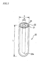
- Fig. 2 shows an example of a tubular hydrogen separation material 20.
- the hydrogen separation material 20 is substantially in a cylindrical shape and has a central hole 23 at the center substantially of a circular cross section extending in the longitudinal direction.
- the hydrogen separation material 20 comprises a porous support 21 as a tube wall and a silica glass membrane 22 in this order in the outer circumference of the central hole 23.
- the central hole 23 is preferably closed at one end 23a. Further, for enlarging the surface area of the tube, the outer diameter T and the inner diameter P may be changed periodically in the longitudinal direction and the thickness can also be changed partially for reinforcing the mechanical strength.
- the porous support 11 is preferably selected from those having a linear thermal expansion coefficient approximate to that of the silica glass membrane 12 in a view of the thermal shock resistance.
- the material for the porous support 11 preferably comprises porous silica glass, in which an element from rare earth elements, group 4B elements, Al, and Ga, or two or more of them in combination can be added to one or both of the silica glass membrane 12 and the porous silica glass constituting the porous support 11. This is because desired mechanical properties and steam resistance can be obtained by adjusting the ingredients of the porous silica glass constituting the porous support 11 or the silica glass membrane 12. For example, in a case of using the hydrogen separation material 10 of the invention for steam reforming of a hydrocarbon fuel, since it is inevitably in contact with steams at 500°C or higher, it is preferred to introduce other ingredients thereby improving the steam resistant performance.
- the porous silica glass constituting the porous support 11 can be manufactured by a manufacturing method such as a sooting method (CVD method) and an injection molding method.
- the forming method is not particularly restricted and means for forming the membrane by surface modification of the porous silica glass constituting the porous support 11 can be used in addition to the sol-gel method or the CVD method.
- Surface modification means that the porous silica glass constituting the porous support 11 is densified to some extent at a portion to form the surface membrane, for example, near the surface of the porous silica glass constituting the porous support 11 into a dense silica glass layer for preparing a hydrogen permeation membrane portion.
- One of the methods includes a heating method. Specifically, this is a method of irradiating, for example, a CO 2 laser, a plasma arc, and an oxyhydrogen flame alone or in combination of plurality of them.
- a heating method for example, a CO 2 laser, a plasma arc, and an oxyhydrogen flame alone or in combination of plurality of them.
- the forming method by the surface modification can increase the bonding strength between the membrane and the support compared with the manufacturing method of manufacturing the porous silica glass and the silica glass membrane constituting the porous support 11 separately and laminating them and the thickness or the size of pores of the silica glass membrane 12 can be controlled simply depending on the extent of the densification.
- the extent for the densification of the silica glass membrane 12 can be set in view of the molecular size of a gas to be separated. With a view point of the hydrogen permeation, it is preferred that the silica glass membrane 12 is densified such that the hole diameter is about 0.3 nm in view of the hydrogen permeation.
- the manufacturing method for the hydrogen separation material of the invention includes (1) a porous support forming step of forming a porous support comprising porous silica glass, and (2) a silica glass membrane forming step of forming a silica glass membrane on the surface of the porous silica glass.
- the manufacturing method for the hydrogen separation material according to the invention is to be described with reference to the drawings.
- the method of manufacturing a porous silica glass is not particularly restricted and includes, for example, a sooting method (CVD method) and injection molding method.
- a preferred example of a manufacturing method for a tubular hydrogen separation material 20 described above, in a case where the porous support 21 comprises porous silica glass includes a method of depositing porous silica glass to the periphery of a dummy rod (deposition step) and then drawing out the dummy rod (drawing out step).
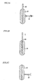
- An embodiment of the method is to be described below with reference to Fig. 3 A, 3B, and 3C .
- Fig. 3A is a view for explaining a deposition step according to this embodiment and Fig. 3B is a view for explaining a drawing out step according to the embodiment.
- a dummy rod 30 is disposed vertically with the top end being downside. Further, it may also be in a configuration disposed horizontally.
- alumina, glass, refractory ceramics, carbon, etc. can be used as a material for the dummy rod 30, alumina, glass, refractory ceramics, carbon, etc. can be used.
- the dummy rod 30, after fixing, is rotated around a central axis as the center.
- fine glass particles are deposited to the outer periphery of the dummy rod 30 by a burner 35 disposed on the side of the dummy rod 30 by an outside CVD method (OVD method).
- An element of rare earth elements, group 4B elements, Al, and Ga or two or more of them in combination can be added to the fine glass particles in accordance with the desired mechanical property and the steam durability.
- the burner 35 Upon deposition of the fine glass particles, the burner 35 is traversed in the axial direction of the dummy rod 30 or the dummy rod 30 is traversed in the axial direction.
- the starting material supplied and the amount of supply can be made different on every traversing cycle.
- the fine glass particles deposited to the outer circumference of the dummy rod 30 have a predetermined bulk density and the distribution of the composition in the radial direction.
- a tubular porous silica glass 25 closed at the top end is manufactured by depositing the fine glass particles also at the top end of the dummy rod 30.
- the porous silica glass may be densified by sintering fine silica glass particles under heating after depositing the fine silica glass particles such that the porosity is within a range from 20 to 70%.
- the porosity may also be controlled by adjusting the temperature at which the fine silica glass particles is deposited. While the temperature of heat sintering after the deposition is not particularly restricted, it is preferably 1000°C to 1400°C. If it is lower than 1000°C, sintering may not sometimes proceed sufficiently. On the other hand, if it exceeds 1400°C, the porosity may sometimes be decreased excessively.
- the temperature is not particularly restricted and, for example, it is preferably from 1400°C to 1700°C. If it is lower than 1400°C, sintering of the fine silica glass particles may not sometimes be progressed sufficiently and if it exceeds 1700°C, the porosity becomes excessively small.
- the deposition temperature is more preferably from 1500°C to 1600°C.
- Fig. 3B The drawing out step after the deposition step is described with reference to Fig. 3B .
- the dummy rod 30 is drawn out from the porous silica glass 25.
- the central hole 23 formed by drawing out does not passing through but the lower end (top end) 23a is closed while being opened only at the upper end (refer to Fig. 2 ).
- carbon or nitride, etc. is preferably coated previously to the surface of the dummy rod 30.
- a silica glass membrane is formed to the surface of the porous support by a sol-gel method, a CVD method, a method of surface modifying the porous silica glass, etc.
- Fig. 3C is a view for explaining the silica glass membrane forming step according to the embodiment.
- a method of forming a silica glass membrane by surface modification of the surface of the porous silica glass by a surface processing apparatus is to be described.
- the porous silica glass 25 obtained by the porous support step is modified at the surface by densifying the surface into a dense silica glass membrane 22 by a surface processing apparatus 36.
- any surface processing device 36 capable of irradiating an energy ray at a high temperature may be used and a CO 2 laser, a plasma arc, an oxyhydrogen burner, etc. may be used alone or in combination of plurality of them.
- the porous support 21 and the silica glass member 22 are formed by surface modification of the porous silica glass 25.
- the extent of the surface modification for the silica glass membrane 22 is not particularly restricted so long as it is within a range that the silica glass membrane 22 functions as a hydrogen permeation membrane and the thickness is preferably from 0.01 to 50 ⁇ m, more preferably, from 0.02 to' 10 ⁇ m and, further preferably, from 0.03 to 5 ⁇ m in view of the hydrogen molecule separatability.
- the silica glass membrane 22 preferably has pores at a diameter of about 0.3 nm so as to allow only the hydrogen molecules to permeate therethrough.
- the silica glass membrane forming step may be conducted naturally also in a state where the porous silica glass 25 is deposited to the periphery of the dummy rod 30.
- a tubular hydrogen separation material 20 can be formed by drawing out only the dummy rod 30.
- the hydrogen separation module according to the invention comprises the hydrogen separation material of the invention and a steam reforming catalyst.
- An embodiment of the hydrogen separation module according to the invention is to be described with reference to Fig. 4.
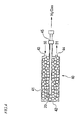
- Fig. 4 is a view for explaining the hydrogen separation module to which the hydrogen separation material 20 is applied.
- the hydrogen separation module 40 shown in Fig. 4 has a hydrogen separation material 20 and a steam reforming catalyst 41 in a reaction vessel 42.
- the reaction vessel 42 has an introduction port 43 for introducing a starting gas 50 into the reaction vessel 42, a discharge port 44 for discharging a discharge gas 51 from the reaction vessel 42, and a disposing port 45 for disposing the hydrogen separation material 20 into the reaction vessel 42.
- the steam reforming catalyst 41 is packed around the hydrogen separation material 20 in the reaction vessel 42.
- the starting gas 50 is obtained by combustion of a fuel such as city gas, propane gas, kerosene, petroleum oil, biomethanol, natural gas, methane hydrate, etc.
- the starting gas 50 is heated to about 500°C after being introduced into the reaction vessel 42 and reformed by the steam reforming catalyst 41 (for example, Ru type catalyst) to generate a hydrogen gas.
- the steam reforming catalyst 41 for example, Ru type catalyst
- the generated hydrogen gas is selectively extracted by the tubular hydrogen separation material 20 and caused to permeate as far as the central hole 23 inside the tube and taken out of the reaction vessel 42. Accordingly, hydrogen generation is promoted in view of chemical equilibrium to attain lowering of reaction temperature. Since CO shifting reaction is taken place simultaneously, the CO shifting catalyst is theoretically unnecessary.
- the hydrogen production apparatus comprises a hydrogen separation module according to the invention. While it is considered that the hydrogen separated and formed by the hydrogen separation module according to the invention is at a high purity of 99% or higher, it is preferred to further include a CO removing module having a CO methanation catalyst, etc. for example, in a case of a hydrogen production apparatus used for stationary domestic fuel cells in order to further decrease the amount of intruded CO (preferably 10 ppm or less). While a CO selective oxidation catalyst may also be used instead of the CO methanation catalyst, this involves a drawback that oxygen or air has to be supplied between the hydrogen separation module and the CO removing module, the hydrogen concentration is lowered due to generation of water by the reaction of hydrogen and oxygen or intrusion of nitrogen.
- a hydrogen production apparatus used for automobile fuel cells since highly pure hydrogen (99.99% or higher) at a further lower CO concentration (less than 1 ppm) is necessary, it is preferred to further include a hydrogen purifying module to which a pressure swing adsorption (PSA) method is applied.
- PSA pressure swing adsorption
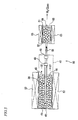
- FIG. 5 is a view for explaining a hydrogen production apparatus comprising a hydrogen separation module 40 and a CO removing module having a CO methanation catalyst.
- a hydrogen production apparatus 60 shown in Fig. 5 has a hydrogen separation module 40 and a CO removing module 65.
- the CO removing module 65 comprises a reaction vessel 61 for taking place a CO removing reaction and a CO methanation catalyst (for example, Ru type catalyst) 62 disposed at the inside thereof.
- a CO methanation catalyst for example, Ru type catalyst
- the hydrogen production apparatus 60 further has a heat generation body 53 for causing steam reforming reaction of the starting gas 50 near the hydrogen separation module 40, and a heat generation body 63 for causing CO removing reaction near the CO removing module 65.
- the CO removing module 65 is connected by way of a connection tube 54 using a connection joint 48 to the hydrogen separation module 40.
- the hydrogen gas generated from the hydrogen separation module 40 is introduced through a connection tube 54 to the CO removing module 65 and put to CO removing reaction.
- the purified hydrogen gas is taken out of the discharge port 64.
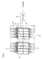
- FIG. 6 is a view for explaining a hydrogen production apparatus having a hydrogen separation module 40 and a hydrogen purification module to which a pressure swing adsorption (PSA) method is applied.
- a hydrogen production apparatus 70 shown in Fig. 6 comprises a plurality of hydrogen separation modules 40 and a hydrogen purifying module (PSA unit) 75 to which the PSA method is applied.
- Each of the hydrogen separation modules 40 is connected at a hydrogen discharge portion (not illustrated) in the hydrogen separation material 20 by way of a connection tube 71 to the PSA unit 75.
- a panel-like heat generation body (shown by dotted line) 72 is disposed near the plurality of hydrogen separation modules 40 to take place steam reforming reaction.
- the generated hydrogen gas is introduced through the connection tube 71 to the PSA unit 75 and then a hydrogen gas at a high purity is produced by removing gas ingredients other than hydrogen.
- a silica glass membrane of 50 nm thickness was formed to the surface of a support comprising a porous alumina or porous zirconia tube sealed at one end with an outer diameter of 10 mm, a thickness of 1 mm, and a length of 300 mm by using a sol-gel method.
- the composite structures were heated in an electric furnace to 500°C and rapidly dropped into water at 30°C (water dropping test) for confirming the thermal shock resistance, the composite structural body was fractured.
- Porous glass with an outer diameter of 10 mm, a thickness of 1 mm, and a length of 30 mm sealed at one end was manufactured by depositing porous glass of a composition described in Table 1 (mol%) to a carbon coated alumina tube sealed at one end by using an outside CVD method and drawing out a dummy rod therefrom.
- a silica glass membrane of 50 nm thickness was formed to the surface of the porous glass by using a sol-gel method.
- a porous glass at an outer diameter of an 10 mm, a thickness of 1 mm and a length of 300 mm sealed at one end was manufacture by depositing a porous glass of a composition (mol%) described in Table 1 by using an outside CVD method to a carbon coated alumina tube sealed at one end and drawing out a dummy rod.
- a silica glass membrane of 50 nm thickness was formed to the surface of the porous glass by using a sol-gel method.
- Example 1 Comp.
- Example 2 Comp.
- Example 3 Example 1 Example 2 Example 3 Porous support Material Alumina Zirconia 80SiO 2 - 20 Al 2 O 3 glass Silica glass 90SiO 2 -10 Al 2 O 3 glass 85SiO 2 -15Al 2 O 3 glass Porosity (%) 50 50 50 50 50 50 50 50 50 50 50 Outer diameter (mm) 10 10 10 10 10 10 10 Thickness (mm) 1 1 1 1 1 1 1 1 Thermal expansion coefficient ( ⁇ 10 -6 /K) 7,3 10.8 2.6 0.7 1.4 1.8 Separation membrane Material Silica glass Silica glass Silica glass Silica glass Thickness (mm) 50 50 50 50 50 50 50 50 50 50 50 50 50 50 50 50 50 50 50 50 50 50 50 50 50 50 50 50 Film forming method Sol-gel method Sol-gel method Sol-gel method Sol-gel method Sol-gel method Water dropping test Support fractured Support fractured Separation membrane fractured No change No change No change No change No change No change No change No change No change No change No change No change No change
- Porous silica glass was deposited to a carbon coat alumina tube sealed at one end by using an outside CVD method. Then, the surface of the porous silica glass was irradiated with a CO 2 laser to form a dense silica glass membrane of 1 ⁇ m thickness. A dummy rod was drawn out from the composite structural body to manufacture a tubular hydrogen separation material with an outer diameter of 16 mm, a thickness of 1.5 mm and a length of 300 mm, a porosity of 40%, and a linear thermal expansion coefficient of 0.7 ⁇ 10 -6 /K.
- Porous silica glass was deposited to a carbon coated alumina tube sealed at one end by using an outside CVD method. Then, the surface of the porous body was irradiated with a plasma arc to form a dense silica glass membrane of 20 ⁇ m thickness. A dummy rod was drawn out from the composite structural body to manufacture a tubular hydrogen separation material with an outer diameter of 10 mm, a thickness of 1 mm, a length of 300 mm, a porosity of 68%, and a linear thermal expansion coefficient of 0.7 ⁇ 10 -6 /K.
- Porous silica glass was deposited to a carbon coated alumina tube sealed at one end by using an outside CVD method. Then, an oxyhydrogen burner flame was applied to the surface of the porous body to form a dense silica glass membrane of 40 ⁇ m thickness. A dummy rod was drawn out from the composite structural body to manufacture a tubular hydrogen separation material with an outer diameter of 16 mm, a thickness of 4 mm, a length of 300 mm, a porosity of 22%, and a linear thermal expansion coefficient of 0.7 ⁇ 10 -6 /K.
- porous silica glass with addition of 1000 ppm of Y, Al., Ti, Ga were deposited respectively to carbon coated alumina tubes sealed at one end by using an outside CVD method. Then, the surface of each porous body was irradiated with a CO 2 laser to form a dense silica glass membrane' of 3 ⁇ m thickness. A dummy rod was drawn out from the composite structural body to manufacture a tubular hydrogen separation material with an outer diameter of 16 mm, a thickness of 1.5 mm, a length of 300 mm, a porosity of 40%, and a linear thermal expansion coefficient of 0.7 ⁇ 10 -6 /K.
- the hydrogen concentration in a gas permeating to the inside of the tubular hydrogen separation material was 99% or higher, the carbon monoxide concentration was about at 500 ppm, and the hydrogen production rate was 0.02 Nm 3 /h. Further, the carbon monoxide concentration after passing the gas through a CO removing module having a commercial Ru type CO methanation catalyst was 10 ppm or less.
- FIG. 6 52 sets of hydrogen separation modules each comprising the tubular hydrogen separation material of Example 9 and the commercial Ru type reforming catalyst were connected as shown in Fig. 6 .
- the hydrogen concentration was 99% or higher and the carbon monoxide concentration was about 500 ppm in a gas permeating to the inside of the hydrogen separation material, and the hydrogen production rate was 1 Nm 3 /h. Further, the hydrogen concentration of the gas was 99.99% or higher and the carbon monoxide concentration was 1 ppm or less after purification by using a commercial PSA type hydrogen purifier.
- Table 2 shows characteristics, etc. of the Examples 4 to 12 described above.
- Example 12 Support portion Material (with addition of element) Silica glass Silica glass Silica glass Silica glass (Y:1000ppm) Silica glass (Ti:1000pm) Silica glass (Al:1000-ppm) Silica glass (Ga:1000 ppm) Silica glass (Al:1000pm) Silica glass (Al:1000ppm) Manufacturing method Outside CVD method+ dummy rod drawing out Outside CVD method+ dummy rod drawing out Outside CVD method+ dummy rod drawing out method+ dummy rod drawing out Outside CVD method+ dummy rod drawing out Outside CVD method+ dummy rod drawing out Outside CVD method+ dummy rod drawing out Outside CVD method+ dummy rod drawing out Outside CVD method+ dummy rod drawing out Outside CVD method+ dummy rod drawing out Outside CVD method+ dummy rod drawing out Outside CVD method+ dummy rod drawing out Outside CVD method+ dummy rod drawing out Outside CVD method+ dummy rod drawing out Outside CVD method+ dummy rod drawing out Outside CVD method+
- a hydrogen separation material more excellent in the thermal shock resistance can be obtained by forming a porous support with a material of an identical quality and having a thermal expansion coefficient of 2 ⁇ 10 -5 /K or less and a thermal expansion coefficient approximate to that of the silica glass membrane.
- a hydrogen separation material of high bonding strength between the membrane and the support can be formed, and the thickness and the size of the pores of the silica glass membrane can be controlled simply depending on the extent of modification (densification).
Landscapes
- Chemical & Material Sciences (AREA)
- Chemical Kinetics & Catalysis (AREA)
- Inorganic Chemistry (AREA)
- Organic Chemistry (AREA)
- Engineering & Computer Science (AREA)
- Combustion & Propulsion (AREA)
- Manufacturing & Machinery (AREA)
- General Health & Medical Sciences (AREA)
- Health & Medical Sciences (AREA)
- Analytical Chemistry (AREA)
- General Chemical & Material Sciences (AREA)
- Oil, Petroleum & Natural Gas (AREA)
- Physics & Mathematics (AREA)
- Optics & Photonics (AREA)
- Separation Using Semi-Permeable Membranes (AREA)
- Hydrogen, Water And Hydrids (AREA)
- Separation Of Gases By Adsorption (AREA)
- Glass Melting And Manufacturing (AREA)
- Re-Forming, After-Treatment, Cutting And Transporting Of Glass Products (AREA)
Abstract
Description
- The present invention concerns a hydrogen separation material for separating hydrogen at high purity from a gas mixture containing hydrogen formed by fuel reforming, etc., as well as a hydrogen separation module and a hydrogen production apparatus having the same and, particularly, it relates to a hydrogen separation material in which a silica-based hydrogen permselective membrane for allowing hydrogen to permeable therethrough selectively is formed on the surface of a porous support and a manufacturing method therefor, as well as a hydrogen separation module and a hydrogen production apparatus having the same.
- In the course of the progress for research and providing development of hydrogen production technique and infrastructure of utilizing hydrogen for realizing the hydrogen energy society, a great demand is expected in the feature for highly pure hydrogen used, for example, in automobile fuel cells, domestic stationary fuel cells, hydrogen stations, and large-scaled chemical plants in the feature, and higher efficiency is demanded for the production thereof.
- For the production of hydrogen at present, a method of steam reforming a hydrocarbon fuel at a temperature of about 700°C (CH4 + H2O → CO + 3H2) and then performing further CO-shifting at about several hundred °C (CO + H2O → CO2 + H2) has been utilized generally with a view point of price competitive power. Ingredients of a gas obtained by way of the reactions described above include, in addition to hydrogen, carbon dioxide, carbon monoxide and, further, unreacted hydrocarbons and water. In solid polymer fuel cells which have been started for popularized domestic use in recent years, purification of hydrogen is not performed for lowering the cost, but a gas mixture at a hydrogen concentration of about 60% is supplied as it is to a fuel electrode of a fuel cell, carbon monoxide that poisons the catalyst of the fuel electrode is oxidized into hydrogen dioxide (CO + 1/2O2 → CO2) before supply, and removed to a concentration of less than 10 ppm. However, since the fuel cell using the gas mixture has lower power generation efficiency compared with a fuel cell using pure hydrogen, a technique of producing hydrogen at a higher purity in a reduced space and at a low cost has been demanded. Further, in automobile fuel cells, it is necessary to supply hydrogen at 99.99% or higher in addition to the restriction for the CO concentration and a technique of mass producing inexpensive highly pure hydrogen is demanded.
- A method of taking out highly pure hydrogen from a hydrogen containing gas mixture includes, for example, an absorption method, a cryogenic separation method, an adsorption method, and a membrane separation method in which the membrane separation method has an advantage that the efficiency is high and the size can be decreased easily. Further, by constituting a membrane reactor having a hydrogen separation membrane inserted therein in a reaction vessel for steam reforming, it is possible to continuously extract hydrogen generated by the reforming reaction from a reaction atmosphere, promote the reforming reaction and the CO shifting reaction simultaneously even at a temperature of about 500°C, thereby producing highly pure hydrogen at high efficiency. Further, in the membrane reactor, expensive noble metal catalysts such as platinum used for CO shifting are not necessary and it is possible to lower the cost and decrease the size of the apparatus. While the purity of a hydrogen gas passing through the hydrogen separation membrane depends on the performance of the hydrogen separation membrane, when it is necessary to further remove CO and improve purification depending on the application use, loads on such steps can be mitigated.
- Several hydrogen separation membranes have been proposed under the background of the advantage in the hydrogen production using the hydrogen separation membrane as has been described above. For example, a non-patent document 1 describes a hydrogen separation membrane in which a palladium alloy membrane is supported on a zirconia porous substrate. In the hydrogen separation membrane, since hydrogen is separated by a method of dissolving hydrogen in the form of atoms into a palladium alloy and diffusing them along the concentration gradient thereby allowing only the pure hydrogen to permeate, highly pure hydrogen can be obtained in principle. A non-patent document 2 describes a hydrogen separation membrane in which a silica glass membrane is supported on an alumina-based porous substrate. The hydrogen separation membrane separates hydrogen by the function of a molecular sieve of selectively allowing hydrogen molecules to permeate by utilizing that the silica glass membrane has pores of a size for allowing only the hydrogen molecules to pass therethrough (0.3 nm).
- Non-Patent Literature 1: "Development of highly durable membrane type LP gas reforming apparatus", Heisei 20 Abstract for Fuel Cell • Hydrogen Technology Development Symposium, Independent Administrate Institution, New Energy and Industry Technology Development MechanismNon-Patent Literature 2: "Development of highly efficient high temperature hydrogen separation membrane", (post fact evaluation) Sub-Committee Proceedings (July 30, Heisei 19), Independent Administrate Institution, New Energy and Industry Technology Development Mechanism.
- However, the palladium alloy membrane/zirconia porous support described in the non-patent document 1 involves a drawback that the mechanical strength is lowered by hydrogen embrittlement of the palladium alloy membrane due to long time use and the palladium alloy membrane is damaged by allying with impurities such as sulfur and iron contained in the starting gas. Further, it is not suitable to mass production since palladium as the starting material is expensive and, in addition, the stable supply is not reliable. While the porous zirconia support is a material having high thermal shock resistance and small difference of a thermal expansion rate relative to the palladium alloy membrane among typical ceramics, the support has a drawback that it is damaged by abrupt temperature change or the palladium alloy membrane is peeled from the porous zirconia support. When water droplets are in contact with ceramics heated to several hundreds °C, cracks are tended to be formed and, accordingly, the ceramic support cannot be used in a location where steams are condensed, particularly, in a case of using the ceramic support for the membrane reactor- Therefore, while it is necessary to airtightly bond the metal member for taking out hydrogen separated from the ceramic substrate to the outside of the membrane reactor at a high temperature heating portion, there exists a problem that a bonded portion is degraded thereby tending to cause seal leakage during long time use. In the silica glass membrane/porous alumina support described in the non-patent document 2, while the damage caused by the degradation of the silica glass membrane is overcome, since alumina is less resistant to thermal shock than zirconia and also has a large difference of the thermal expansion rate relative to the silica glass, this tends to result a problem of suffering from damage due to the abrupt temperature change or peeling of the silica glass membrane from the support as described above.
- The present invention has been achieved in view of the foregoing subjects in the existent hydrogen separation membrane and the object thereof is to provide a hydrogen separation material resistant to thermal shock, having good adhesion between the membrane and the support, excellent in the hydrogen separation characteristic, and applicable to a hydrogen separation membrane, etc. and a manufacturing method therefor, as well as a hydrogen separation module and a hydrogen production apparatus having the same.
- The present inventors have made earnest studies for attaining the foregoing object and, as a result, have found that a hydrogen separation material resistant to thermal shock and excellent in the hydrogen separation characteristic can be obtained by using a silica glass membrane as the membrane and defining the linear thermal expansion coefficient of a support in a hydrogen separation material comprising the membrane and the support therefor, and a manufacturing method including a porous support forming step of forming a porous support comprising porous silica glass and a silica glass membrane forming step of forming a silica glass membrane on the surface of the porous silica glass, and have accomplished the present invention based on the finding.
That is, the hydrogen separation material and the manufacturing method therefor, as well as the hydrogen separation module and the hydrogen production apparatus having the same according to the invention are as described below. -
- (1) A hydrogen separation material of the invention is characterized in that a silica glass membrane is formed on a porous support having a linear thermal expansion coefficient of 2 × 10⁻⁶/K or less.
- (2) A preferred embodiment of the hydrogen separation material of the invention is characterized in that the porous support comprises porous silica glass.
- (3) Another preferred embodiment of the hydrogen separation material of the invention is characterized in that the shape is tubular.
- (4) Further, a preferred embodiment of the hydrogen separation material of the invention is characterized in that at least one of elements selected from rare earth elements, group 4B elements, A1 and Ga is added to the porous silica glass and/or silica glass membrane.
- (5) A further preferred embodiment of the hydrogen separation material of the present invention is characterized in that the porous silica glass is densified by surface modification thereby forming the silica glass membrane on a porous support comprising
- (6) A further preferred embodiment of the hydrogen separation material of the invention is characterized in that the surface modification is a processing of irradiating at least one means selected from a CO2 laser, a plasma arc, and a oxyhydrogen flame thereby densifying the surface of the porous silica glass.
-
- (7) A manufacturing method for the hydrogen separation material according to the invention is characterized by including a porous support forming step of forming a porous support comprising porous silica glass and a silica glass membrane forming step of forming a silica glass membrane on the surface of the porous silica glass.
- (8) Further, a preferred embodiment of the manufacturing method for the hydrogen separation material according to the invention is characterized in that the porous support forming step is a step of depositing porous silica glass at the periphery of a dummy rod and then drawing out the dummy load to form a tubular porous support comprising the porous silica glass.
- (9) Further, another preferred embodiment of the manufacturing method for the hydrogen separation material according to the invention is characterized in that the porous support forming step is a step of depositing porous silica glass with addition of at least one elements selected from rare earth element, group 4B elements, Al, and Ga to the periphery of a dummy rod and then drawing out the dummy rod thereby forming a tubular porous support comprising porous silica glass.
- (10) A manufacturing method for a hydrogen separation material according to the invention is characterized by including a porous support forming step of forming a porous support comprising the porous silica glass, and a silica glass membrane forming step of densifying the surface of the porous silica glass thereby forming a dense silica glass membrane.
- (11) A further preferred embodiment of the manufacturing method for the hydrogen separation material according to the invention is characterized in that the silica glass membrane forming step is a step of irradiating at least one means selected from a CO2 laser, a plasma arc, and an oxyhydrogen burner thereby densifying the surface of the porous silica glass.
- (12) A further hydrogen separation material according to the invention is characterized in that it is obtained by any one of the manufacturing methods for the hydrogen separation material according to the invention described above.
-
- (13) A further preferred embodiment of the hydrogen separation material according to the invention is characterized in that the porosity of the porous support is from 20 to 70%.
- (14) A further preferred embodiment of the hydrogen separation material according to the invention is characterized in that the thickness of the porous support is from 0.2 to 5 mm.
- (15) A further preferred embodiment of the hydrogen separation material according to the invention is characterized in that the thickness of the silica glass is from 0.01 to 50 µm.
- (16) A hydrogen separation module according to the invention is characterized by including one of the hydrogen separation materials of the invention described above and a steam reforming catalyst.
- (17) A hydrogen production apparatus according to the invention is characterized by including the hydrogen separation module of the invention described above.
-
- (18) Another hydrogen production apparatus according to the invention is characterized by including the hydrogen separation module of the invention described above and a CO removing module.
- (19) Further, a preferred embodiment of the hydrogen production apparatus according to the invention is characterized in that the Co removing module has a CO methanation catalyst.
- (20) A preferred embodiment of the hydrogen production apparatus according to the invention is characterized by including a hydrogen purification module to which the hydrogen separation module of the invention described above and a pressure swing adsorption (PAS) method are applied.
- According to the invention, it is possible to provide a hydrogen separation material resistant to thermal shock, having good adhesion between the membrane and support, excellent in the hydrogen separation characteristic, and applicable to a hydrogen separation membrane, etc., and a manufacturing method therefor, as well as a hydrogen separation module and a hydrogen production apparatus having the same.
-
-
Fig. 1 is a partial cross sectional view showing an embodiment of a hydrogen separation material according to the invention. -
Fig. 2 is a schematic view showing an embodiment of a hydrogen separation material according to the invention. -
Fig. 3A, 3B, and 3C is a view for explaining a deposition step (a), a drawing out step (b), and a silica glass membrane forming step (c) as an embodiment of a manufacturing method for a hydrogen separation material according to the invention. -
Fig. 4 is a view explaining a hydrogen separation module to which ahydrogen separation material 20 is applied. -
Fig. 5 is a view explaining an example of a hydrogen production apparatus to which ahydrogen separation module 40 is applied. -
Fig. 6 is a view explaining another example of the hydrogen production apparatus to which thehydrogen separation module 40 is applied. - A hydrogen separation material and a manufacturing method therefor, as well as a hydrogen separation module and a hydrogen production apparatus having the same according to the invention are to be described specifically with reference to the drawings.
-
Fig. 1 is a partial cross sectional view showing an example of a hydrogen separation material according to the invention. Inhydrogen separation material 10, asilica glass membrane 12 is formed on aporous support 11 having a linear thermal expansion coefficient of 2 × 10⁻⁶/K or less.
In the invention, thesilica glass membrane 12 is used as a hydrogen permeation membrane as described above thereby suppressing degradation of the membrane caused by hydrogen embrittlement and reaction with impurities in the starting material. While the thickness of thesilica glass membrane 12 is not particularly restricted, it is preferably from 0.01 to 50 µm, more preferably, from 0.02 to 10 µm and, further preferably, 0.03 to 5 µm. In a case where it is less than n.01 µm, the hydrogen purity of the permeating gas is excessively low and, in a case where it exceeds 50 µm, the hydrogen permeation rate is excessively low sometimes making it difficult to obtain a sufficient hydrogen separation performance in view of practical use. - Referring to the support for the
silica glass membrane 12, when theporous support 11 is used, the thin membrane can be supported with no interference to the hydrogen permeation in thesilica glass membrane 12. While the porosity of theporous support 11 is not particularly restricted, it is preferably from 20 to 70% in view of the balance between the mechanical strength and the gas permeability. "porosity" can be calculated as a ratio of an air volume occupying per unit volume.
Further, the linear thermal expansion coefficient of theporous support 11 is 2 × 10⁻⁶/K or less as described above. In a case where it exceeds 2 × 10⁻⁶/K, generated thermal stress increases and no desired thermal shock resistance can be obtained. While the material of theporous support 11 is not particularly restricted so long as it has a defined linear thermal expansion coefficient, those having a linear thermal expansion coefficient approximate to that of thesilica glass membrane 12 are preferred with a view point of the thermal impact resistance.
While the thickness of theporous support 11 is not particularly restricted, it is preferably from 0.2 to 5 mm, more preferably, from 0.5 to 3 mm and, further preferably, from 0.2 to 5 mm in view of the balance between the mechanical strength and the gas permeability. - While the shape of the
hydrogen separation material 10 of the invention is not particularly restricted but may be in any optional shape, for example, a planar shape. it is preferably tubular for increasing the area of contact with a hydrogen containing gas mixture in view of the reaction efficiency.
Fig. 2 shows an example of a tubularhydrogen separation material 20. Thehydrogen separation material 20 is substantially in a cylindrical shape and has acentral hole 23 at the center substantially of a circular cross section extending in the longitudinal direction. Thehydrogen separation material 20 comprises aporous support 21 as a tube wall and asilica glass membrane 22 in this order in the outer circumference of thecentral hole 23. It has an outer diameter T of 2 mm to 50 mm, an inner diameter (diameter for the central hole 23) P of 1.6 mm to 48 mm, and a length L of about 200 mm to 400 mm. Thecentral hole 23 is preferably closed at oneend 23a. Further, for enlarging the surface area of the tube, the outer diameter T and the inner diameter P may be changed periodically in the longitudinal direction and the thickness can also be changed partially for reinforcing the mechanical strength. - As described above, the
porous support 11 is preferably selected from those having a linear thermal expansion coefficient approximate to that of thesilica glass membrane 12 in a view of the thermal shock resistance. In thehydrogen separation material 10 of the invention, the material for theporous support 11 preferably comprises porous silica glass, in which an element from rare earth elements, group 4B elements, Al, and Ga, or two or more of them in combination can be added to one or both of thesilica glass membrane 12 and the porous silica glass constituting theporous support 11. This is because desired mechanical properties and steam resistance can be obtained by adjusting the ingredients of the porous silica glass constituting theporous support 11 or thesilica glass membrane 12.
For example, in a case of using thehydrogen separation material 10 of the invention for steam reforming of a hydrocarbon fuel, since it is inevitably in contact with steams at 500°C or higher, it is preferred to introduce other ingredients thereby improving the steam resistant performance. - Further, the porous silica glass constituting the
porous support 11 can be manufactured by a manufacturing method such as a sooting method (CVD method) and an injection molding method. Also for thesilica glass membrane 12, the forming method is not particularly restricted and means for forming the membrane by surface modification of the porous silica glass constituting theporous support 11 can be used in addition to the sol-gel method or the CVD method. "Surface modification" means that the porous silica glass constituting theporous support 11 is densified to some extent at a portion to form the surface membrane, for example, near the surface of the porous silica glass constituting theporous support 11 into a dense silica glass layer for preparing a hydrogen permeation membrane portion. One of the methods includes a heating method. Specifically, this is a method of irradiating, for example, a CO2 laser, a plasma arc, and an oxyhydrogen flame alone or in combination of plurality of them.
As described above, while thesilica glass film 12 can be manufactured also by the sol-gel method or the CVD method, the forming method by the surface modification can increase the bonding strength between the membrane and the support compared with the manufacturing method of manufacturing the porous silica glass and the silica glass membrane constituting theporous support 11 separately and laminating them and the thickness or the size of pores of thesilica glass membrane 12 can be controlled simply depending on the extent of the densification. The extent for the densification of thesilica glass membrane 12 can be set in view of the molecular size of a gas to be separated. With a view point of the hydrogen permeation, it is preferred that thesilica glass membrane 12 is densified such that the hole diameter is about 0.3 nm in view of the hydrogen permeation. - Further, another hydrogen separation material of the invention is obtained by the following manufacturing method.
- The manufacturing method for the hydrogen separation material of the invention includes (1) a porous support forming step of forming a porous support comprising porous silica glass, and (2) a silica glass membrane forming step of forming a silica glass membrane on the surface of the porous silica glass. The manufacturing method for the hydrogen separation material according to the invention is to be described with reference to the drawings.
- The method of manufacturing a porous silica glass is not particularly restricted and includes, for example, a sooting method (CVD method) and injection molding method.
A preferred example of a manufacturing method for a tubularhydrogen separation material 20 described above, in a case where theporous support 21 comprises porous silica glass, includes a method of depositing porous silica glass to the periphery of a dummy rod (deposition step) and then drawing out the dummy rod (drawing out step). An embodiment of the method is to be described below with reference toFig. 3 A, 3B, and 3C . -
Fig. 3A is a view for explaining a deposition step according to this embodiment andFig. 3B is a view for explaining a drawing out step according to the embodiment. InFig. 3A , adummy rod 30 is disposed vertically with the top end being downside. Further, it may also be in a configuration disposed horizontally. As a material for thedummy rod 30, alumina, glass, refractory ceramics, carbon, etc. can be used. Thedummy rod 30, after fixing, is rotated around a central axis as the center. Then, fine glass particles are deposited to the outer periphery of thedummy rod 30 by aburner 35 disposed on the side of thedummy rod 30 by an outside CVD method (OVD method). An element of rare earth elements, group 4B elements, Al, and Ga or two or more of them in combination can be added to the fine glass particles in accordance with the desired mechanical property and the steam durability. That is, according to the manufacturing method, the ingredients can be controlled easily. - Upon deposition of the fine glass particles, the
burner 35 is traversed in the axial direction of thedummy rod 30 or thedummy rod 30 is traversed in the axial direction. The starting material supplied and the amount of supply can be made different on every traversing cycle. Thus, the fine glass particles deposited to the outer circumference of thedummy rod 30 have a predetermined bulk density and the distribution of the composition in the radial direction. Further, a tubularporous silica glass 25 closed at the top end is manufactured by depositing the fine glass particles also at the top end of thedummy rod 30. - The porous silica glass may be densified by sintering fine silica glass particles under heating after depositing the fine silica glass particles such that the porosity is within a range from 20 to 70%. Alternatively, the porosity may also be controlled by adjusting the temperature at which the fine silica glass particles is deposited. While the temperature of heat sintering after the deposition is not particularly restricted, it is preferably 1000°C to 1400°C. If it is lower than 1000°C, sintering may not sometimes proceed sufficiently. On the other hand, if it exceeds 1400°C, the porosity may sometimes be decreased excessively. Further, also when the porosity is controlled depending on the deposition temperature, the temperature is not particularly restricted and, for example, it is preferably from 1400°C to 1700°C. If it is lower than 1400°C, sintering of the fine silica glass particles may not sometimes be progressed sufficiently and if it exceeds 1700°C, the porosity becomes excessively small. The deposition temperature is more preferably from 1500°C to 1600°C.
- The drawing out step after the deposition step is described with reference to
Fig. 3B . InFig. 3B , thedummy rod 30 is drawn out from theporous silica glass 25. Thecentral hole 23 formed by drawing out does not passing through but the lower end (top end) 23a is closed while being opened only at the upper end (refer toFig. 2 ). For facilitating the drawing out, carbon or nitride, etc. is preferably coated previously to the surface of thedummy rod 30. - After forming the porous support comprising porous silica glass, a silica glass membrane is formed to the surface of the porous support by a sol-gel method, a CVD method, a method of surface modifying the porous silica glass, etc.
Fig. 3C is a view for explaining the silica glass membrane forming step according to the embodiment. A method of forming a silica glass membrane by surface modification of the surface of the porous silica glass by a surface processing apparatus is to be described.
Theporous silica glass 25 obtained by the porous support step is modified at the surface by densifying the surface into a densesilica glass membrane 22 by asurface processing apparatus 36. Anysurface processing device 36, for example, capable of irradiating an energy ray at a high temperature may be used and a CO2 laser, a plasma arc, an oxyhydrogen burner, etc. may be used alone or in combination of plurality of them. Theporous support 21 and thesilica glass member 22 are formed by surface modification of theporous silica glass 25.
The extent of the surface modification for thesilica glass membrane 22 is not particularly restricted so long as it is within a range that thesilica glass membrane 22 functions as a hydrogen permeation membrane and the thickness is preferably from 0.01 to 50 µm, more preferably, from 0.02 to' 10 µm and, further preferably, from 0.03 to 5 µm in view of the hydrogen molecule separatability. Further, thesilica glass membrane 22 preferably has pores at a diameter of about 0.3 nm so as to allow only the hydrogen molecules to permeate therethrough. - While a drawing out step of drawing out only the
dummy rod 30 from theporous silica glass 25 deposited to the periphery of thedummy rod 30 is performed before the silica glass membrane forming step, the silica glass membrane forming step may be conducted naturally also in a state where theporous silica glass 25 is deposited to the periphery of thedummy rod 30. After the silica glass membrane forming step, a tubularhydrogen separation material 20 can be formed by drawing out only thedummy rod 30. - The hydrogen separation module according to the invention comprises the hydrogen separation material of the invention and a steam reforming catalyst. An embodiment of the hydrogen separation module according to the invention is to be described with reference to
Fig. 4. Fig. 4 is a view for explaining the hydrogen separation module to which thehydrogen separation material 20 is applied.
Thehydrogen separation module 40 shown inFig. 4 has ahydrogen separation material 20 and asteam reforming catalyst 41 in areaction vessel 42. Thereaction vessel 42 has anintroduction port 43 for introducing a startinggas 50 into thereaction vessel 42, adischarge port 44 for discharging adischarge gas 51 from thereaction vessel 42, and a disposingport 45 for disposing thehydrogen separation material 20 into thereaction vessel 42. Thesteam reforming catalyst 41 is packed around thehydrogen separation material 20 in thereaction vessel 42.
The startinggas 50 is obtained by combustion of a fuel such as city gas, propane gas, kerosene, petroleum oil, biomethanol, natural gas, methane hydrate, etc. The startinggas 50 is heated to about 500°C after being introduced into thereaction vessel 42 and reformed by the steam reforming catalyst 41 (for example, Ru type catalyst) to generate a hydrogen gas. During the reforming reaction, the generated hydrogen gas is selectively extracted by the tubularhydrogen separation material 20 and caused to permeate as far as thecentral hole 23 inside the tube and taken out of thereaction vessel 42. Accordingly, hydrogen generation is promoted in view of chemical equilibrium to attain lowering of reaction temperature. Since CO shifting reaction is taken place simultaneously, the CO shifting catalyst is theoretically unnecessary. - The hydrogen production apparatus according to the invention comprises a hydrogen separation module according to the invention. While it is considered that the hydrogen separated and formed by the hydrogen separation module according to the invention is at a high purity of 99% or higher, it is preferred to further include a CO removing module having a CO methanation catalyst, etc. for example, in a case of a hydrogen production apparatus used for stationary domestic fuel cells in order to further decrease the amount of intruded CO (preferably 10 ppm or less). While a CO selective oxidation catalyst may also be used instead of the CO methanation catalyst, this involves a drawback that oxygen or air has to be supplied between the hydrogen separation module and the CO removing module, the hydrogen concentration is lowered due to generation of water by the reaction of hydrogen and oxygen or intrusion of nitrogen. In a case of a hydrogen production apparatus used for automobile fuel cells, since highly pure hydrogen (99.99% or higher) at a further lower CO concentration (less than 1 ppm) is necessary, it is preferred to further include a hydrogen purifying module to which a pressure swing adsorption (PSA) method is applied.
- An embodiment of the hydrogen production apparatus according to the invention is to be described with reference to
Figs. 5 and6 .
Fig. 5 is a view for explaining a hydrogen production apparatus comprising ahydrogen separation module 40 and a CO removing module having a CO methanation catalyst.
Ahydrogen production apparatus 60 shown inFig. 5 has ahydrogen separation module 40 and aCO removing module 65. TheCO removing module 65 comprises areaction vessel 61 for taking place a CO removing reaction and a CO methanation catalyst (for example, Ru type catalyst) 62 disposed at the inside thereof. Further, thehydrogen production apparatus 60 further has aheat generation body 53 for causing steam reforming reaction of the startinggas 50 near thehydrogen separation module 40, and aheat generation body 63 for causing CO removing reaction near theCO removing module 65. TheCO removing module 65 is connected by way of a connection tube 54 using a connection joint 48 to thehydrogen separation module 40. The hydrogen gas generated from thehydrogen separation module 40 is introduced through a connection tube 54 to theCO removing module 65 and put to CO removing reaction. The purified hydrogen gas is taken out of thedischarge port 64. -
Fig. 6 is a view for explaining a hydrogen production apparatus having ahydrogen separation module 40 and a hydrogen purification module to which a pressure swing adsorption (PSA) method is applied.
Ahydrogen production apparatus 70 shown inFig. 6 comprises a plurality ofhydrogen separation modules 40 and a hydrogen purifying module (PSA unit) 75 to which the PSA method is applied. Each of thehydrogen separation modules 40 is connected at a hydrogen discharge portion (not illustrated) in thehydrogen separation material 20 by way of aconnection tube 71 to thePSA unit 75. A panel-like heat generation body (shown by dotted line) 72 is disposed near the plurality ofhydrogen separation modules 40 to take place steam reforming reaction. The generated hydrogen gas is introduced through theconnection tube 71 to thePSA unit 75 and then a hydrogen gas at a high purity is produced by removing gas ingredients other than hydrogen. - The present invention is to be described more specifically with reference to embodiments according to the invention. The invention is not restricted to such examples.
- A silica glass membrane of 50 nm thickness was formed to the surface of a support comprising a porous alumina or porous zirconia tube sealed at one end with an outer diameter of 10 mm, a thickness of 1 mm, and a length of 300 mm by using a sol-gel method. When the composite structures were heated in an electric furnace to 500°C and rapidly dropped into water at 30°C (water dropping test) for confirming the thermal shock resistance, the composite structural body was fractured.
- Porous glass with an outer diameter of 10 mm, a thickness of 1 mm, and a length of 30 mm sealed at one end was manufactured by depositing porous glass of a composition described in Table 1 (mol%) to a carbon coated alumina tube sealed at one end by using an outside CVD method and drawing out a dummy rod therefrom. A silica glass membrane of 50 nm thickness was formed to the surface of the porous glass by using a sol-gel method. When the composite structural body was heated to 500°C in an electric furnace and dropped rapidly into water at 30°C, while the composite structural body was not fractured but formation of cracks in the silica glass membrane was confirmed under electron microscopic observation.
- A porous glass at an outer diameter of an 10 mm, a thickness of 1 mm and a length of 300 mm sealed at one end was manufacture by depositing a porous glass of a composition (mol%) described in Table 1 by using an outside CVD method to a carbon coated alumina tube sealed at one end and drawing out a dummy rod. A silica glass membrane of 50 nm thickness was formed to the surface of the porous glass by using a sol-gel method. When the composite structural bodies were heated to 500°C in an electric furnace and dropped rapidly into water at 30°C, fracture of the composite structural body and formation of cracks in the silica glass membrane were not observed.
-
[Table 1] Comp. Example 1 Comp. Example 2 Comp. Example 3 Example 1 Example 2 Example 3 Porous support Material Alumina Zirconia 80SiO2 - 20 Al2O3 glass Silica glass 90SiO2 -10 Al2O3 glass 85SiO2 -15Al2O3 glass Porosity (%) 50 50 50 50 50 50 Outer diameter (mm) 10 10 10 10 10 10 Thickness (mm) 1 1 1 1 1 1 Thermal expansion coefficient (× 10-6/K) 7,3 10.8 2.6 0.7 1.4 1.8 Separation membrane Material Silica glass Silica glass Silica glass Silica glass Silica glass Silica glass Thickness (mm) 50 50 50 50 50 50 Film forming method Sol-gel method Sol-gel method Sol-gel method Sol-gel method Sol-gel method Sol-gel method Water dropping test Support fractured Support fractured Separation membrane fractured No change No change No change - It is apparent from the result described above that a hydrogen separation material of excellent thermal shock resistance can be obtained by setting the thermal expansion coefficient of the porous support to 2 × 10⁻⁶/K or less.
- Porous silica glass was deposited to a carbon coat alumina tube sealed at one end by using an outside CVD method. Then, the surface of the porous silica glass was irradiated with a CO2 laser to form a dense silica glass membrane of 1 µm thickness. A dummy rod was drawn out from the composite structural body to manufacture a tubular hydrogen separation material with an outer diameter of 16 mm, a thickness of 1.5 mm and a length of 300 mm, a porosity of 40%, and a linear thermal expansion coefficient of 0.7 × 10⁻⁶/K. When a 50%H2 - 50%N2 gas at 0.2 MPaG was supplied to the outside of the hydrogen separation material, the hydrogen concentration in a gas at an atmospheric pressure permeating to the inside of the hydrogen separation material was 99% or higher and the hydrogen permeation coefficient at 550°C was 4 × 10⁻⁷ mol · m-2 · s-1 · Pa-1. Further, after exposing the outside of the hydrogen separation material to steams at 0.2 MPaG and 600°C for 120 hours, when the surface was observed under an electron microscope, defects such as cracks were not observed while a denatured layer of extremely small area was recognized.
- Porous silica glass was deposited to a carbon coated alumina tube sealed at one end by using an outside CVD method. Then, the surface of the porous body was irradiated with a plasma arc to form a dense silica glass membrane of 20 µm thickness. A dummy rod was drawn out from the composite structural body to manufacture a tubular hydrogen separation material with an outer diameter of 10 mm, a thickness of 1 mm, a length of 300 mm, a porosity of 68%, and a linear thermal expansion coefficient of 0.7 × 10⁻⁶/K. When a 50
%H 2 50%N2 gas at 0.2 MPaG was supplied to the outside of the hydrogen separation material, the hydrogen concentration in a gas at an atmospheric pressure permeating to the inside of the hydrogen separation material was 99% or higher and the hydrogen permeation coefficient at 550°C was 0.3 × 10⁻⁷ mol · m-2 · s-1 · Pa-1. - Porous silica glass was deposited to a carbon coated alumina tube sealed at one end by using an outside CVD method. Then, an oxyhydrogen burner flame was applied to the surface of the porous body to form a dense silica glass membrane of 40 µm thickness. A dummy rod was drawn out from the composite structural body to manufacture a tubular hydrogen separation material with an outer diameter of 16 mm, a thickness of 4 mm, a length of 300 mm, a porosity of 22%, and a linear thermal expansion coefficient of 0.7 × 10⁻⁶/K. When a 50%H2 - 50%N2 gas at 0.2 MPaG was supplied to the outside of the hydrogen separation material, the hydrogen concentration in a gas at an atmospheric pressure permeating to the inside of the hydrogen separation material was 99% or higher and the hydrogen permeation coefficient at 550°C was 0.05 × 10⁻⁷ mol · m-2 · s-1 · Pa-1.
- Four types of porous silica glass with addition of 1000 ppm of Y, Al., Ti, Ga were deposited respectively to carbon coated alumina tubes sealed at one end by using an outside CVD method. Then, the surface of each porous body was irradiated with a CO2 laser to form a dense silica glass membrane' of 3 µm thickness. A dummy rod was drawn out from the composite structural body to manufacture a tubular hydrogen separation material with an outer diameter of 16 mm, a thickness of 1.5 mm, a length of 300 mm, a porosity of 40%, and a linear thermal expansion coefficient of 0.7 × 10⁻⁶/K. When a 50%H2 - 50%N2 gas at 0.2 MPaG was supplied to the outside of the hydrogen separation material, the hydrogen concentration in a gas at an atmospheric pressure permeating to the inside of the hydrogen separation material was 99% or higher and the hydrogen permeation coefficient at 550°C was 1 × 10⁻⁷ mol · m-2 · s-1 · Pa-1 in each of the cases Further, after exposing the outside of the tubular hydrogen separation material to steams at 0.2 MPaG, and at 600°C for 120 hours, when the surface was observed under an electron microscope, detects such as denatured layer or cracking were not observed.
- As shown in
Fig. 5 , a starting gas comprising H2O/CH4 = 3 was supplied to a reaction vessel of a hydrogen separation module having the tubular hydrogen separation material of Example 9 and a commercial Ru type reforming catalyst was supplied to take place hydrogen reforming at a temperature of 550°C and a pressure of 0.5 MPaG. The hydrogen concentration in a gas permeating to the inside of the tubular hydrogen separation material was 99% or higher, the carbon monoxide concentration was about at 500 ppm, and the hydrogen production rate was 0.02 Nm3/h. Further, the carbon monoxide concentration after passing the gas through a CO removing module having a commercial Ru type CO methanation catalyst was 10 ppm or less. - 52 sets of hydrogen separation modules each comprising the tubular hydrogen separation material of Example 9 and the commercial Ru type reforming catalyst were connected as shown in
Fig. 6 . A starting gas comprising H2O/CH4 = 3 was supplied to the reaction vessels of the entire modules and steam reforming was performed at a temperature of 550°C and a pressure of 0.5 MPaG. The hydrogen concentration was 99% or higher and the carbon monoxide concentration was about 500 ppm in a gas permeating to the inside of the hydrogen separation material, and the hydrogen production rate was 1 Nm3/h. Further, the hydrogen concentration of the gas was 99.99% or higher and the carbon monoxide concentration was 1 ppm or less after purification by using a commercial PSA type hydrogen purifier. - Table 2 shows characteristics, etc. of the Examples 4 to 12 described above.
-
[Table 2] Characteristic Example 4 Example 5 Example 6 Example 7 Example 8 Example 9 Example 10 Example 11 Example 12 Support portion Material (with addition of element) Silica glass Silica glass Silica glass Silica glass (Y:1000ppm) Silica glass (Ti:1000pm) Silica glass (Al:1000-ppm) Silica glass (Ga:1000 ppm) Silica glass (Al:1000pm) Silica glass (Al:1000ppm) Manufacturing method Outside CVD method+ dummy rod drawing out Outside CVD method+ dummy rod drawing out Outside CVD method+ dummy rod drawing out method+ dummy rod drawing out Outside CVD method+ dummy rod drawing out Outside CVD method+ dummy rod drawing out Outside CVD method+ dummy rod drawing out Outside CVD method+ dummy rod drawing out Outside CVD method+ dummy rod drawing out Thikness (mm) 15 1 4 15 15 15 15 15 15 Outer diameter (mm) 16 10 16 16 16 16 16 16 16 Length (mm) 300 300 300 300 300 300 300 300 300 Linear thermal expansion coefficient (106/K) 0.7 0.7 0.7 0.7 0.7 0.7 0.7 0.7 0.7 Porosity (%) 40 68 22 40 40 40 40 40 40 Membrane portion Film forming method Surface modification (CO2 laser) Surface modification (plasma are) Surface modification (Oxyhydrogen burner) Surface modification (CO2 laser) modification (CO2 laser) Surface modification (CO2 laser) modification (CO2 laser) Surface modification (CO2 laser) Surface modification (CO2 laser) Thikness (µm) 1 20 40 3 3 3 3 3 3 Hydrogen separation characteristic H2 concentration (%) 99 or higher 99 or higher 99 or higher 99 or higher 99 or higher 99 or higher 99 or higher 99 or higher 99 or higher H2 permation coefficient (104 mol·m2·s-1•Pa-1) 4 0.3 0.05 1 1 1 1 1 1 Steam durability Membrane portion surface state Partially modified - - good good good good good good Reforming characteristics Hydrogen concentration(%) - - - - - - - 99 or higher 99 or higher Hydrogen manufacturing rate (Nm3/hb) - - - - - - - 0.02 1 CO removing method - - - - - - - CO methanation catalyst PSA CO concentration (ppm) - - - - - - - <10 <1 *: "-" in the table shows that measurement was not conducted. - As can be seen from the table, a hydrogen separation material more excellent in the thermal shock resistance can be obtained by forming a porous support with a material of an identical quality and having a thermal expansion coefficient of 2 × 10⁻⁵/K or less and a thermal expansion coefficient approximate to that of the silica glass membrane. Particularly, according to the method of modifying the surface of the porous silica glass into a silica glass membrane, a hydrogen separation material of high bonding strength between the membrane and the support can be formed, and the thickness and the size of the pores of the silica glass membrane can be controlled simply depending on the extent of modification (densification).
- 10, 20 --- hydrogen separation material, 11, 21porous support, 12, 22 --- silica glass membrane, 23central hole, 23a --- top end of the central hole, 25porous silica glass, 30 ---- dummy rod, 35 --- burner, 36surface processing device, 40 --- hydrogen separation module, 41 --- hydrogen reforming catalyst, 42, 61 --- reaction vessel, 43 --- introduction port, 44, 64 --- discharge port, 45disposing port, 48 --- connection joint, 50 --- starting gas, 51 --- discharge gas, 53, 63, 72 --- heat generation body, 54, 71 --- connection tube, 60, 70 --- hydrogen production apparatus, 62 --- CO methanation catalyst, 65 --- CO removing module, 75 --- hydrogen purifying module (PSA unit), Touter diameter, P --- inner diameter, L --- length
- While the present invention has been described specifically with reference to specific embodiments, it will be apparent to a person skilled in the art that various changes and modifications are possible without departing the gist of the spirit and the scope of the invention.
The present application is based on the Japanese Patent Application filed on December 11, 2009 (Japanese Patent Application No.2009-282210
Claims (20)
- A hydrogen separation material in which a silica glass membrane is formed on a porous support having a linear thermal expansion coefficient of 2 × 10⁻⁶/K or less.
- A hydrogen separation material according to claim 1, wherein the porous support comprises porous silica glass.
- A hydrogen separation material according to claim 2 having a tubular shape.
- A hydrogen separation material according to claim 2 or 3, wherein at least one element selected from rare earth elements, group 4B elements, Al, and Ga is added to the porous silica glass and/or silica glass membrane.
- A hydrogen separation material according to any one of claims 2 to 4, wherein the silica glass membrane is formed on the porous support comprising the porous silica glass by surface modifying and densifying the porous support comprising the porous silica glass.
- A hydrogen separation material according to any one of claims 2 to 5, wherein the surface modification is a processing of densifying the surface of the porous silica glass by irradiating at least one means selected from a CO2 laser, a plasma arc, and an oxyhydrogen burner.
- A method of manufacturing a hydrogen separation material including a porous support forming step of forming a porous support comprising porous silica glass and a silica glass membrane forming step of forming a silica glass membrane on the surface of the porous silica glass.
- A method of manufacturing a hydrogen separation material according to claim 7, wherein the porous support forming step is a step of depositing porous silica glass to the periphery of a dummy rod and then drawing out the dummy rod to form a tubular porous support comprising the porous silica glass.
- A method of manufacturing a hydrogen separation material according to claim 8, wherein the porous support forming step is a step of depositing a porous silica glass with addition of at least one element selected from rare earth elements, group 4B elements, Al, and Ga to the periphery of the dummy rod and then drawing out the dummy rod to form a tubular porous support comprising the porous silica glass.
- A method of manufacturing a hydrogen separation material according to any one of claims 7 to 9, including a porous support forming step of forming a porous support comprising the porous silica glass, and a silica glass membrane forming step of densifying the surface of the porous silica glass thereby forming a dense silica glass membrane.
- A method of manufacturing a hydrogen separation material according to claim 10, wherein the silica glass membrane forming step is a step of irradiating at least one means selected from a CO2 laser, a plasma arc, and an oxyhydrogen burner thereby densifying the surface of the porous silica glass.
- A hydrogen separation material obtained by the method according to any one of claims 7 to 11.
- A hydrogen separation material according to any one of claims 1 to 6, and 12, wherein the porosity of the porous support is from 20 to 70%.
- A hydrogen separation material according to any one of claims 1, to 6, 12, and 13, wherein the thickness of the porous support is from 0.2 to 5 mm.
- A hydrogen separation material according to any one of claims 1 to 6, and 12 to 14, wherein the thickness of the silica glass membrane is from 0.01 to 50 µm.
- A hydrogen separation module comprising the hydrogen separation material according to any one of claims 1 to 6, and 12 to 15, and a steam reforming catalyst.
- A hydrogen production apparatus having the hydrogen separation module according to claim 16.
- A hydrogen production apparatus having the hydrogen separation module according to claim 16 and a CO removing module.
- A hydrogen production apparatus according to claim 18, wherein the CO removing module has a CO methanation catalyst.
- A hydrogen production apparatus having a hydrogen separation module according to claim 16 and a hydrogen purifying module to which a pressure swing adsorption (PSA) method is applied.
Applications Claiming Priority (2)
| Application Number | Priority Date | Filing Date | Title |
|---|---|---|---|
| JP2009282210 | 2009-12-11 | ||
| PCT/JP2010/072201 WO2011071138A1 (en) | 2009-12-11 | 2010-12-10 | Silica-containing hydrogen-separating material and process for production thereof, and hydrogen separation module and hydrogen production apparatus each comprises the hydrogen-separating material |
Publications (3)
| Publication Number | Publication Date |
|---|---|
| EP2511005A1 true EP2511005A1 (en) | 2012-10-17 |
| EP2511005A4 EP2511005A4 (en) | 2016-11-16 |
| EP2511005B1 EP2511005B1 (en) | 2020-02-19 |
Family
ID=44145681
Family Applications (1)
| Application Number | Title | Priority Date | Filing Date |
|---|---|---|---|
| EP10836057.9A Active EP2511005B1 (en) | 2009-12-11 | 2010-12-10 | Process for production of silica-containing hydrogen-separating material |
Country Status (7)
| Country | Link |
|---|---|
| US (1) | US9126151B2 (en) |
| EP (1) | EP2511005B1 (en) |
| JP (1) | JP5757243B2 (en) |
| KR (1) | KR101880769B1 (en) |
| CN (1) | CN102652036A (en) |
| CA (1) | CA2783961A1 (en) |
| WO (1) | WO2011071138A1 (en) |
Families Citing this family (9)
| Publication number | Priority date | Publication date | Assignee | Title |
|---|---|---|---|---|
| JP5757186B2 (en) * | 2011-07-25 | 2015-07-29 | 住友電気工業株式会社 | Fluid separation material and manufacturing method thereof |
| JP5821438B2 (en) * | 2011-09-07 | 2015-11-24 | 住友電気工業株式会社 | Method for producing porous glass tube |
| JP5906929B2 (en) * | 2012-05-07 | 2016-04-20 | 住友電気工業株式会社 | GLASS TUBE, ITS MANUFACTURING METHOD, AND FLUID SEPARATION MATERIAL USING GLASS TUBE |
| JP6154692B2 (en) * | 2013-07-25 | 2017-06-28 | 住友電気工業株式会社 | Fluid separation material and manufacturing method thereof |
| US10222519B2 (en) * | 2016-03-10 | 2019-03-05 | Coorstek Kk | Composite silica glass made light diffusion member |
| JP6955190B2 (en) * | 2017-01-11 | 2021-10-27 | 日本電気硝子株式会社 | Glass member and its manufacturing method |
| JP7738486B2 (en) * | 2019-06-04 | 2025-09-12 | メンブリオン・インコーポレイテッド | Ceramic cation exchange materials |
| JP7561416B2 (en) * | 2020-09-25 | 2024-10-04 | 学校法人 工学院大学 | Hydrogen production device, hydrogen separation membrane, and method for producing hydrogen separation membrane |
| CN117863707B (en) * | 2024-03-11 | 2024-05-10 | 杭州邦齐州科技有限公司 | A pre-bonded glass separation jig and separation method thereof |
Family Cites Families (25)
| Publication number | Priority date | Publication date | Assignee | Title |
|---|---|---|---|---|
| US3620704A (en) * | 1969-12-18 | 1971-11-16 | Texas Instruments Inc | Method and apparatus for forming and drawing fused metal-oxide tubes |
| JPS5992923A (en) * | 1982-11-15 | 1984-05-29 | Nippon Telegr & Teleph Corp <Ntt> | Manufacture of porous glass membrane |
| JPS61204006A (en) * | 1985-03-07 | 1986-09-10 | Ngk Insulators Ltd | Separation membrane and its production |
| US4689150A (en) * | 1985-03-07 | 1987-08-25 | Ngk Insulators, Ltd. | Separation membrane and process for manufacturing the same |
| JPS62258704A (en) * | 1986-05-06 | 1987-11-11 | Asahi Glass Co Ltd | Separating membrane for fluid |
| US6461408B2 (en) * | 1995-11-06 | 2002-10-08 | Robert E. Buxbaum | Hydrogen generator |
| US6537352B2 (en) * | 1996-10-30 | 2003-03-25 | Idatech, Llc | Hydrogen purification membranes, components and fuel processing systems containing the same |
| JPH1119458A (en) * | 1997-07-07 | 1999-01-26 | Sumitomo Electric Ind Ltd | Gas separation membrane and method for producing the same |
| JP3316173B2 (en) * | 1997-11-06 | 2002-08-19 | 株式会社ノリタケカンパニーリミテド | Substrate for supporting zeolite membrane |
| WO2000045940A1 (en) * | 1999-02-02 | 2000-08-10 | Virginia Tech Intellectual Properties, Inc. | Hydrogen-selective silica based membrane |
| JP2001137673A (en) * | 1999-11-12 | 2001-05-22 | Sumitomo Electric Ind Ltd | Hydrogen separation complex |
| EP1342500A4 (en) * | 2000-12-05 | 2006-05-03 | Sumitomo Electric Industries | HYDROGEN PERMEABLE STRUCTURE |
| JP2002282640A (en) * | 2001-03-28 | 2002-10-02 | Kyocera Corp | How to maintain the gas separation module |
| JP2003040623A (en) * | 2001-07-26 | 2003-02-13 | Sumitomo Electric Ind Ltd | Method for producing glass particulate deposit |
| JP2003176140A (en) * | 2001-12-06 | 2003-06-24 | Tokuyama Toshiba Ceramics Co Ltd | Transparent quartz glass and its manufacturing method |
| JP4184037B2 (en) | 2002-10-29 | 2008-11-19 | 東京瓦斯株式会社 | Hydrogen production equipment |
| DE602004007938T2 (en) * | 2003-08-27 | 2008-04-17 | Ngk Insulators, Ltd. | GASTRENNKÖRPER AND METHOD FOR THE MANUFACTURE THEREOF |
| JP4562565B2 (en) * | 2005-03-23 | 2010-10-13 | 株式会社ノリタケカンパニーリミテド | Inorganic porous separation membrane and method for producing the same |
| JP4490383B2 (en) * | 2006-03-13 | 2010-06-23 | 日本碍子株式会社 | Hydrogen gas separator fixing structure and hydrogen gas separator using the same |
| US7585356B2 (en) * | 2006-05-01 | 2009-09-08 | Virginia Tech Intellectual Properties, Inc. | Hydrothermally-stable silica-based composite membranes for hydrogen separation |
| JP4371427B2 (en) * | 2007-03-29 | 2009-11-25 | 株式会社ノリタケカンパニーリミテド | Method for producing hydrogen gas separator |
| US20090107330A1 (en) * | 2007-10-30 | 2009-04-30 | Yunfeng Gu | Amorphous silica hybrid membrane structure |
| JP2011516382A (en) * | 2008-04-03 | 2011-05-26 | ヘレーウス クヴァルツグラース ゲゼルシャフト ミット ベシュレンクテル ハフツング ウント コンパニー コマンディートゲゼルシャフト | Method for producing synthetic quartz glass |
| JP2009282210A (en) | 2008-05-21 | 2009-12-03 | Hitachi Maxell Ltd | Reflective polarizer and liquid crystal display device using it |
| WO2011119469A1 (en) * | 2010-03-22 | 2011-09-29 | T3 Scientific Llc | Hydrogen selective protective coating, coated article and method |
-
2010
- 2010-12-10 CN CN201080056142XA patent/CN102652036A/en active Pending
- 2010-12-10 EP EP10836057.9A patent/EP2511005B1/en active Active
- 2010-12-10 JP JP2011545256A patent/JP5757243B2/en not_active Expired - Fee Related
- 2010-12-10 US US13/515,230 patent/US9126151B2/en not_active Expired - Fee Related
- 2010-12-10 WO PCT/JP2010/072201 patent/WO2011071138A1/en not_active Ceased
- 2010-12-10 CA CA 2783961 patent/CA2783961A1/en not_active Abandoned
- 2010-12-10 KR KR1020127015087A patent/KR101880769B1/en not_active Expired - Fee Related
Non-Patent Citations (1)
| Title |
|---|
| See references of WO2011071138A1 * |
Also Published As
| Publication number | Publication date |
|---|---|
| US20130022509A1 (en) | 2013-01-24 |
| EP2511005A4 (en) | 2016-11-16 |
| KR101880769B1 (en) | 2018-07-20 |
| KR20120114261A (en) | 2012-10-16 |
| WO2011071138A1 (en) | 2011-06-16 |
| CA2783961A1 (en) | 2011-06-16 |
| CN102652036A (en) | 2012-08-29 |
| EP2511005B1 (en) | 2020-02-19 |
| JPWO2011071138A1 (en) | 2013-04-22 |
| US9126151B2 (en) | 2015-09-08 |
| JP5757243B2 (en) | 2015-07-29 |
Similar Documents
| Publication | Publication Date | Title |
|---|---|---|
| EP2511005B1 (en) | Process for production of silica-containing hydrogen-separating material | |
| Yoshino et al. | Development of tubular substrates, silica based membranes and membrane modules for hydrogen separation at high temperature | |
| Cardoso et al. | Inorganic membranes for hydrogen separation | |
| EP1499452B1 (en) | Process for preparing palladium alloy composite membranes for use in hydrogen separation | |
| AU766490B2 (en) | Hydrogen-selective silica based membrane | |
| US7959716B2 (en) | Hydrogen separation membrane on a porous substrate | |
| JP2011206612A (en) | Membrane separation type reactor and method of producing hydrogen | |
| CN102083748B (en) | Method and apparatus for producing hydrogen | |
| US9272269B2 (en) | Catalytic hollow fibers | |
| Hu et al. | Low-cost iron (Fe) hollow fiber membrane for hydrogen separation | |
| JP4521358B2 (en) | Hydrogen or helium permeable membrane, storage membrane and method of forming the same | |
| JP2004123415A (en) | Porous ceramic material and method for producing the same | |
| JP5757186B2 (en) | Fluid separation material and manufacturing method thereof | |
| KR102482676B1 (en) | Method for producing a crystallized laminated film by sequentially laminating powder particles on a cylindrical or tubular support | |
| JP2012200675A (en) | Hydrogen separating material and method of manufacturing the same | |
| KR102567038B1 (en) | Hydrogen separation layer having superior heat-stability and method for producing the same | |
| JP2012071999A (en) | Method for producing porous material, porous material, hydrogen separation module, and hydrogen production apparatus | |
| WO2016104049A1 (en) | Gas separation method | |
| JP5821438B2 (en) | Method for producing porous glass tube | |
| JP5906863B2 (en) | Glass tube and manufacturing method thereof | |
| JP5928047B2 (en) | Glass tube and manufacturing method thereof | |
| JP5410937B2 (en) | Hydrogen production equipment | |
| Barboiu et al. | Ultra-microporous silica membranes for He purification | |
| JP2013234085A (en) | Glass tube and method for producing the same | |
| Gopalakrishnan et al. | High performance hydrogen selective membranes prepared using rapid processing method |
Legal Events
| Date | Code | Title | Description |
|---|---|---|---|
| PUAI | Public reference made under article 153(3) epc to a published international application that has entered the european phase |
Free format text: ORIGINAL CODE: 0009012 |
|
| 17P | Request for examination filed |
Effective date: 20120611 |
|
| AK | Designated contracting states |
Kind code of ref document: A1 Designated state(s): AL AT BE BG CH CY CZ DE DK EE ES FI FR GB GR HR HU IE IS IT LI LT LU LV MC MK MT NL NO PL PT RO RS SE SI SK SM TR |
|
| DAX | Request for extension of the european patent (deleted) | ||
| RA4 | Supplementary search report drawn up and despatched (corrected) |
Effective date: 20161017 |
|
| RIC1 | Information provided on ipc code assigned before grant |
Ipc: B01D 53/22 20060101ALI20161010BHEP Ipc: B01D 69/12 20060101ALI20161010BHEP Ipc: C01B 3/56 20060101ALI20161010BHEP Ipc: C01B 3/38 20060101ALI20161010BHEP Ipc: B01D 69/04 20060101ALI20161010BHEP Ipc: B01D 71/02 20060101AFI20161010BHEP Ipc: B01D 69/10 20060101ALI20161010BHEP |
|
| STAA | Information on the status of an ep patent application or granted ep patent |
Free format text: STATUS: EXAMINATION IS IN PROGRESS |
|
| 17Q | First examination report despatched |
Effective date: 20180405 |
|
| GRAP | Despatch of communication of intention to grant a patent |
Free format text: ORIGINAL CODE: EPIDOSNIGR1 |
|
| STAA | Information on the status of an ep patent application or granted ep patent |
Free format text: STATUS: GRANT OF PATENT IS INTENDED |
|
| INTG | Intention to grant announced |
Effective date: 20190918 |
|
| GRAS | Grant fee paid |
Free format text: ORIGINAL CODE: EPIDOSNIGR3 |
|
| GRAA | (expected) grant |
Free format text: ORIGINAL CODE: 0009210 |
|
| STAA | Information on the status of an ep patent application or granted ep patent |
Free format text: STATUS: THE PATENT HAS BEEN GRANTED |
|
| AK | Designated contracting states |
Kind code of ref document: B1 Designated state(s): AL AT BE BG CH CY CZ DE DK EE ES FI FR GB GR HR HU IE IS IT LI LT LU LV MC MK MT NL NO PL PT RO RS SE SI SK SM TR |
|
| REG | Reference to a national code |
Ref country code: GB Ref legal event code: FG4D |
|
| REG | Reference to a national code |
Ref country code: CH Ref legal event code: EP |
|
| REG | Reference to a national code |
Ref country code: DE Ref legal event code: R096 Ref document number: 602010063191 Country of ref document: DE |
|
| REG | Reference to a national code |
Ref country code: AT Ref legal event code: REF Ref document number: 1234295 Country of ref document: AT Kind code of ref document: T Effective date: 20200315 |
|
| REG | Reference to a national code |
Ref country code: IE Ref legal event code: FG4D |
|
| REG | Reference to a national code |
Ref country code: NL Ref legal event code: MP Effective date: 20200219 |
|
| PG25 | Lapsed in a contracting state [announced via postgrant information from national office to epo] |
Ref country code: FI Free format text: LAPSE BECAUSE OF FAILURE TO SUBMIT A TRANSLATION OF THE DESCRIPTION OR TO PAY THE FEE WITHIN THE PRESCRIBED TIME-LIMIT Effective date: 20200219 Ref country code: NO Free format text: LAPSE BECAUSE OF FAILURE TO SUBMIT A TRANSLATION OF THE DESCRIPTION OR TO PAY THE FEE WITHIN THE PRESCRIBED TIME-LIMIT Effective date: 20200519 Ref country code: RS Free format text: LAPSE BECAUSE OF FAILURE TO SUBMIT A TRANSLATION OF THE DESCRIPTION OR TO PAY THE FEE WITHIN THE PRESCRIBED TIME-LIMIT Effective date: 20200219 |
|
| REG | Reference to a national code |
Ref country code: LT Ref legal event code: MG4D |
|
| PG25 | Lapsed in a contracting state [announced via postgrant information from national office to epo] |
Ref country code: LV Free format text: LAPSE BECAUSE OF FAILURE TO SUBMIT A TRANSLATION OF THE DESCRIPTION OR TO PAY THE FEE WITHIN THE PRESCRIBED TIME-LIMIT Effective date: 20200219 Ref country code: SE Free format text: LAPSE BECAUSE OF FAILURE TO SUBMIT A TRANSLATION OF THE DESCRIPTION OR TO PAY THE FEE WITHIN THE PRESCRIBED TIME-LIMIT Effective date: 20200219 Ref country code: HR Free format text: LAPSE BECAUSE OF FAILURE TO SUBMIT A TRANSLATION OF THE DESCRIPTION OR TO PAY THE FEE WITHIN THE PRESCRIBED TIME-LIMIT Effective date: 20200219 Ref country code: BG Free format text: LAPSE BECAUSE OF FAILURE TO SUBMIT A TRANSLATION OF THE DESCRIPTION OR TO PAY THE FEE WITHIN THE PRESCRIBED TIME-LIMIT Effective date: 20200519 Ref country code: IS Free format text: LAPSE BECAUSE OF FAILURE TO SUBMIT A TRANSLATION OF THE DESCRIPTION OR TO PAY THE FEE WITHIN THE PRESCRIBED TIME-LIMIT Effective date: 20200619 Ref country code: GR Free format text: LAPSE BECAUSE OF FAILURE TO SUBMIT A TRANSLATION OF THE DESCRIPTION OR TO PAY THE FEE WITHIN THE PRESCRIBED TIME-LIMIT Effective date: 20200520 |
|
| PG25 | Lapsed in a contracting state [announced via postgrant information from national office to epo] |
Ref country code: NL Free format text: LAPSE BECAUSE OF FAILURE TO SUBMIT A TRANSLATION OF THE DESCRIPTION OR TO PAY THE FEE WITHIN THE PRESCRIBED TIME-LIMIT Effective date: 20200219 |
|
| PG25 | Lapsed in a contracting state [announced via postgrant information from national office to epo] |
Ref country code: RO Free format text: LAPSE BECAUSE OF FAILURE TO SUBMIT A TRANSLATION OF THE DESCRIPTION OR TO PAY THE FEE WITHIN THE PRESCRIBED TIME-LIMIT Effective date: 20200219 Ref country code: CZ Free format text: LAPSE BECAUSE OF FAILURE TO SUBMIT A TRANSLATION OF THE DESCRIPTION OR TO PAY THE FEE WITHIN THE PRESCRIBED TIME-LIMIT Effective date: 20200219 Ref country code: ES Free format text: LAPSE BECAUSE OF FAILURE TO SUBMIT A TRANSLATION OF THE DESCRIPTION OR TO PAY THE FEE WITHIN THE PRESCRIBED TIME-LIMIT Effective date: 20200219 Ref country code: SK Free format text: LAPSE BECAUSE OF FAILURE TO SUBMIT A TRANSLATION OF THE DESCRIPTION OR TO PAY THE FEE WITHIN THE PRESCRIBED TIME-LIMIT Effective date: 20200219 Ref country code: PT Free format text: LAPSE BECAUSE OF FAILURE TO SUBMIT A TRANSLATION OF THE DESCRIPTION OR TO PAY THE FEE WITHIN THE PRESCRIBED TIME-LIMIT Effective date: 20200712 Ref country code: SM Free format text: LAPSE BECAUSE OF FAILURE TO SUBMIT A TRANSLATION OF THE DESCRIPTION OR TO PAY THE FEE WITHIN THE PRESCRIBED TIME-LIMIT Effective date: 20200219 Ref country code: DK Free format text: LAPSE BECAUSE OF FAILURE TO SUBMIT A TRANSLATION OF THE DESCRIPTION OR TO PAY THE FEE WITHIN THE PRESCRIBED TIME-LIMIT Effective date: 20200219 Ref country code: EE Free format text: LAPSE BECAUSE OF FAILURE TO SUBMIT A TRANSLATION OF THE DESCRIPTION OR TO PAY THE FEE WITHIN THE PRESCRIBED TIME-LIMIT Effective date: 20200219 Ref country code: LT Free format text: LAPSE BECAUSE OF FAILURE TO SUBMIT A TRANSLATION OF THE DESCRIPTION OR TO PAY THE FEE WITHIN THE PRESCRIBED TIME-LIMIT Effective date: 20200219 |
|
| REG | Reference to a national code |
Ref country code: AT Ref legal event code: MK05 Ref document number: 1234295 Country of ref document: AT Kind code of ref document: T Effective date: 20200219 |
|
| REG | Reference to a national code |
Ref country code: DE Ref legal event code: R097 Ref document number: 602010063191 Country of ref document: DE |
|
| PLBE | No opposition filed within time limit |
Free format text: ORIGINAL CODE: 0009261 |
|
| STAA | Information on the status of an ep patent application or granted ep patent |
Free format text: STATUS: NO OPPOSITION FILED WITHIN TIME LIMIT |
|
| 26N | No opposition filed |
Effective date: 20201120 |
|
| PG25 | Lapsed in a contracting state [announced via postgrant information from national office to epo] |
Ref country code: AT Free format text: LAPSE BECAUSE OF FAILURE TO SUBMIT A TRANSLATION OF THE DESCRIPTION OR TO PAY THE FEE WITHIN THE PRESCRIBED TIME-LIMIT Effective date: 20200219 Ref country code: IT Free format text: LAPSE BECAUSE OF FAILURE TO SUBMIT A TRANSLATION OF THE DESCRIPTION OR TO PAY THE FEE WITHIN THE PRESCRIBED TIME-LIMIT Effective date: 20200219 |
|
| PGFP | Annual fee paid to national office [announced via postgrant information from national office to epo] |
Ref country code: DE Payment date: 20201124 Year of fee payment: 11 |
|
| PG25 | Lapsed in a contracting state [announced via postgrant information from national office to epo] |
Ref country code: PL Free format text: LAPSE BECAUSE OF FAILURE TO SUBMIT A TRANSLATION OF THE DESCRIPTION OR TO PAY THE FEE WITHIN THE PRESCRIBED TIME-LIMIT Effective date: 20200219 Ref country code: SI Free format text: LAPSE BECAUSE OF FAILURE TO SUBMIT A TRANSLATION OF THE DESCRIPTION OR TO PAY THE FEE WITHIN THE PRESCRIBED TIME-LIMIT Effective date: 20200219 |
|
| REG | Reference to a national code |
Ref country code: CH Ref legal event code: PL |
|
| GBPC | Gb: european patent ceased through non-payment of renewal fee |
Effective date: 20201210 |
|
| PG25 | Lapsed in a contracting state [announced via postgrant information from national office to epo] |
Ref country code: MC Free format text: LAPSE BECAUSE OF FAILURE TO SUBMIT A TRANSLATION OF THE DESCRIPTION OR TO PAY THE FEE WITHIN THE PRESCRIBED TIME-LIMIT Effective date: 20200219 |
|
| REG | Reference to a national code |
Ref country code: BE Ref legal event code: MM Effective date: 20201231 |
|
| PG25 | Lapsed in a contracting state [announced via postgrant information from national office to epo] |
Ref country code: IE Free format text: LAPSE BECAUSE OF NON-PAYMENT OF DUE FEES Effective date: 20201210 Ref country code: LU Free format text: LAPSE BECAUSE OF NON-PAYMENT OF DUE FEES Effective date: 20201210 Ref country code: FR Free format text: LAPSE BECAUSE OF NON-PAYMENT OF DUE FEES Effective date: 20201231 |
|
| PG25 | Lapsed in a contracting state [announced via postgrant information from national office to epo] |
Ref country code: LI Free format text: LAPSE BECAUSE OF NON-PAYMENT OF DUE FEES Effective date: 20201231 Ref country code: CH Free format text: LAPSE BECAUSE OF NON-PAYMENT OF DUE FEES Effective date: 20201231 Ref country code: GB Free format text: LAPSE BECAUSE OF NON-PAYMENT OF DUE FEES Effective date: 20201210 |
|
| PG25 | Lapsed in a contracting state [announced via postgrant information from national office to epo] |
Ref country code: TR Free format text: LAPSE BECAUSE OF FAILURE TO SUBMIT A TRANSLATION OF THE DESCRIPTION OR TO PAY THE FEE WITHIN THE PRESCRIBED TIME-LIMIT Effective date: 20200219 Ref country code: MT Free format text: LAPSE BECAUSE OF FAILURE TO SUBMIT A TRANSLATION OF THE DESCRIPTION OR TO PAY THE FEE WITHIN THE PRESCRIBED TIME-LIMIT Effective date: 20200219 Ref country code: CY Free format text: LAPSE BECAUSE OF FAILURE TO SUBMIT A TRANSLATION OF THE DESCRIPTION OR TO PAY THE FEE WITHIN THE PRESCRIBED TIME-LIMIT Effective date: 20200219 |
|
| PG25 | Lapsed in a contracting state [announced via postgrant information from national office to epo] |
Ref country code: MK Free format text: LAPSE BECAUSE OF FAILURE TO SUBMIT A TRANSLATION OF THE DESCRIPTION OR TO PAY THE FEE WITHIN THE PRESCRIBED TIME-LIMIT Effective date: 20200219 Ref country code: AL Free format text: LAPSE BECAUSE OF FAILURE TO SUBMIT A TRANSLATION OF THE DESCRIPTION OR TO PAY THE FEE WITHIN THE PRESCRIBED TIME-LIMIT Effective date: 20200219 |
|
| REG | Reference to a national code |
Ref country code: DE Ref legal event code: R119 Ref document number: 602010063191 Country of ref document: DE |
|
| PG25 | Lapsed in a contracting state [announced via postgrant information from national office to epo] |
Ref country code: BE Free format text: LAPSE BECAUSE OF NON-PAYMENT OF DUE FEES Effective date: 20201231 |
|
| PG25 | Lapsed in a contracting state [announced via postgrant information from national office to epo] |
Ref country code: DE Free format text: LAPSE BECAUSE OF NON-PAYMENT OF DUE FEES Effective date: 20220701 |