EP2510224B1 - Turbinenblatt für eine bidirektional anströmbare wasserturbine - Google Patents
Turbinenblatt für eine bidirektional anströmbare wasserturbine Download PDFInfo
- Publication number
- EP2510224B1 EP2510224B1 EP20100797994 EP10797994A EP2510224B1 EP 2510224 B1 EP2510224 B1 EP 2510224B1 EP 20100797994 EP20100797994 EP 20100797994 EP 10797994 A EP10797994 A EP 10797994A EP 2510224 B1 EP2510224 B1 EP 2510224B1
- Authority
- EP
- European Patent Office
- Prior art keywords
- profile
- channel
- turbine blade
- eccentric
- profile side
- Prior art date
- Legal status (The legal status is an assumption and is not a legal conclusion. Google has not performed a legal analysis and makes no representation as to the accuracy of the status listed.)
- Not-in-force
Links
Images


Classifications
-
- F—MECHANICAL ENGINEERING; LIGHTING; HEATING; WEAPONS; BLASTING
- F03—MACHINES OR ENGINES FOR LIQUIDS; WIND, SPRING, OR WEIGHT MOTORS; PRODUCING MECHANICAL POWER OR A REACTIVE PROPULSIVE THRUST, NOT OTHERWISE PROVIDED FOR
- F03B—MACHINES OR ENGINES FOR LIQUIDS
- F03B3/00—Machines or engines of reaction type; Parts or details peculiar thereto
- F03B3/12—Blades; Blade-carrying rotors
- F03B3/121—Blades, their form or construction
-
- F—MECHANICAL ENGINEERING; LIGHTING; HEATING; WEAPONS; BLASTING
- F03—MACHINES OR ENGINES FOR LIQUIDS; WIND, SPRING, OR WEIGHT MOTORS; PRODUCING MECHANICAL POWER OR A REACTIVE PROPULSIVE THRUST, NOT OTHERWISE PROVIDED FOR
- F03B—MACHINES OR ENGINES FOR LIQUIDS
- F03B3/00—Machines or engines of reaction type; Parts or details peculiar thereto
- F03B3/12—Blades; Blade-carrying rotors
-
- F—MECHANICAL ENGINEERING; LIGHTING; HEATING; WEAPONS; BLASTING
- F03—MACHINES OR ENGINES FOR LIQUIDS; WIND, SPRING, OR WEIGHT MOTORS; PRODUCING MECHANICAL POWER OR A REACTIVE PROPULSIVE THRUST, NOT OTHERWISE PROVIDED FOR
- F03B—MACHINES OR ENGINES FOR LIQUIDS
- F03B17/00—Other machines or engines
-
- F—MECHANICAL ENGINEERING; LIGHTING; HEATING; WEAPONS; BLASTING
- F03—MACHINES OR ENGINES FOR LIQUIDS; WIND, SPRING, OR WEIGHT MOTORS; PRODUCING MECHANICAL POWER OR A REACTIVE PROPULSIVE THRUST, NOT OTHERWISE PROVIDED FOR
- F03B—MACHINES OR ENGINES FOR LIQUIDS
- F03B3/00—Machines or engines of reaction type; Parts or details peculiar thereto
- F03B3/12—Blades; Blade-carrying rotors
- F03B3/126—Rotors for essentially axial flow, e.g. for propeller turbines
-
- F—MECHANICAL ENGINEERING; LIGHTING; HEATING; WEAPONS; BLASTING
- F05—INDEXING SCHEMES RELATING TO ENGINES OR PUMPS IN VARIOUS SUBCLASSES OF CLASSES F01-F04
- F05B—INDEXING SCHEME RELATING TO WIND, SPRING, WEIGHT, INERTIA OR LIKE MOTORS, TO MACHINES OR ENGINES FOR LIQUIDS COVERED BY SUBCLASSES F03B, F03D AND F03G
- F05B2210/00—Working fluid
- F05B2210/40—Flow geometry or direction
- F05B2210/404—Flow geometry or direction bidirectional, i.e. in opposite, alternating directions
-
- F—MECHANICAL ENGINEERING; LIGHTING; HEATING; WEAPONS; BLASTING
- F05—INDEXING SCHEMES RELATING TO ENGINES OR PUMPS IN VARIOUS SUBCLASSES OF CLASSES F01-F04
- F05B—INDEXING SCHEME RELATING TO WIND, SPRING, WEIGHT, INERTIA OR LIKE MOTORS, TO MACHINES OR ENGINES FOR LIQUIDS COVERED BY SUBCLASSES F03B, F03D AND F03G
- F05B2240/00—Components
- F05B2240/20—Rotors
- F05B2240/30—Characteristics of rotor blades, i.e. of any element transforming dynamic fluid energy to or from rotational energy and being attached to a rotor
- F05B2240/301—Cross-section characteristics
-
- F—MECHANICAL ENGINEERING; LIGHTING; HEATING; WEAPONS; BLASTING
- F05—INDEXING SCHEMES RELATING TO ENGINES OR PUMPS IN VARIOUS SUBCLASSES OF CLASSES F01-F04
- F05B—INDEXING SCHEME RELATING TO WIND, SPRING, WEIGHT, INERTIA OR LIKE MOTORS, TO MACHINES OR ENGINES FOR LIQUIDS COVERED BY SUBCLASSES F03B, F03D AND F03G
- F05B2250/00—Geometry
- F05B2250/70—Shape
- F05B2250/71—Shape curved
- F05B2250/713—Shape curved inflexed
-
- F—MECHANICAL ENGINEERING; LIGHTING; HEATING; WEAPONS; BLASTING
- F05—INDEXING SCHEMES RELATING TO ENGINES OR PUMPS IN VARIOUS SUBCLASSES OF CLASSES F01-F04
- F05B—INDEXING SCHEME RELATING TO WIND, SPRING, WEIGHT, INERTIA OR LIKE MOTORS, TO MACHINES OR ENGINES FOR LIQUIDS COVERED BY SUBCLASSES F03B, F03D AND F03G
- F05B2250/00—Geometry
- F05B2250/70—Shape
- F05B2250/72—Shape symmetric
-
- Y—GENERAL TAGGING OF NEW TECHNOLOGICAL DEVELOPMENTS; GENERAL TAGGING OF CROSS-SECTIONAL TECHNOLOGIES SPANNING OVER SEVERAL SECTIONS OF THE IPC; TECHNICAL SUBJECTS COVERED BY FORMER USPC CROSS-REFERENCE ART COLLECTIONS [XRACs] AND DIGESTS
- Y02—TECHNOLOGIES OR APPLICATIONS FOR MITIGATION OR ADAPTATION AGAINST CLIMATE CHANGE
- Y02E—REDUCTION OF GREENHOUSE GAS [GHG] EMISSIONS, RELATED TO ENERGY GENERATION, TRANSMISSION OR DISTRIBUTION
- Y02E10/00—Energy generation through renewable energy sources
- Y02E10/20—Hydro energy
-
- Y—GENERAL TAGGING OF NEW TECHNOLOGICAL DEVELOPMENTS; GENERAL TAGGING OF CROSS-SECTIONAL TECHNOLOGIES SPANNING OVER SEVERAL SECTIONS OF THE IPC; TECHNICAL SUBJECTS COVERED BY FORMER USPC CROSS-REFERENCE ART COLLECTIONS [XRACs] AND DIGESTS
- Y02—TECHNOLOGIES OR APPLICATIONS FOR MITIGATION OR ADAPTATION AGAINST CLIMATE CHANGE
- Y02E—REDUCTION OF GREENHOUSE GAS [GHG] EMISSIONS, RELATED TO ENERGY GENERATION, TRANSMISSION OR DISTRIBUTION
- Y02E10/00—Energy generation through renewable energy sources
- Y02E10/30—Energy from the sea, e.g. using wave energy or salinity gradient
Definitions
- the invention relates to a bidirectionally inflatable turbine blade, for a water turbine, which is preferably used in a diving power generation plant for the production of energy from a bidirectional flow of water.
- a tracking mechanism For energy from a directional flow, such as a tidal current, by means of a freestanding, propeller-shaped turbine usually a tracking mechanism is used, which rotates a nacelle with the attached turbine into the flow. If there are essentially two oppositely directed main flow directions, as in the case of ebb and flow in a tidal current, such a directional tracking can be realized by a folding or rotating device which pivots the nacelle from a first to a second position.
- massive rotary or hinged hinge systems must be used.
- the water turbine drives an electric generator to provide a device which prevents twisting of the outgoing from the electric generator power cable.
- a bidirectionally inflatable water turbine was in the WO 2006/125959 A1 proposed to select a double symmetrical profile as profile contour for the turbine blades of a rotor-shaped water turbine.
- a first symmetry axis represents the chord line.
- the profile is symmetrical to a center line defined as perpendicular to the chord at 50% of the chord length.
- the result is a lenticular profile, which ensures identical profile contours for a bidirectional flow.
- the disadvantage is that due to the double-selected symmetry for the profile contour compared to a one-sided flowed, curved profile results in a lower efficiency. Furthermore, there are disadvantages due to downstream flow separations and increased flow resistance of the turbine blades.
- the invention has for its object to make a turbine blade so that a bidirectional flow is possible.
- This turbine blade should be suitable to be used for a propeller-shaped turbine of a diving power plant, the turbine blade should be characterized by a high efficiency and low Lijnsverwindung for a flow from both directions.
- the invention is based on the known point-symmetrical profiles with an S-shaped skeleton line and a symmetrical thickness distribution to the center line of the profile.
- This profile is now further developed in such a way that an overflow device is provided from a first profile side to a second profile side.
- the turbine blade profile can be adapted substantially to the fluidic conditions, without having to follow competing structural mechanical requirements in the construction of the turbine blade.
- elongate, slim profiles can be used, which lead to a high glide ratio.
- the fastenings of the turbine blade to the hub of the rotating unit must absorb reduced torques and can be simplified according to design and manufacturing technology.
- the overflow device comprises a plurality of overflow channels whose orientation is adapted to the bidirectional flow direction.
- the overflow device is formed by a split blade profile. In this case, there is at least one partial section in the middle region of the overall profile, for which the thickness distribution along the S-shaped skeleton line assumes the value zero.
- the overflow device of the invention comprises overflow channels, which can be closed depending on the direction of flow.
- overflow channels can also be arranged outside the central region of the profile.
- the closing of the transfer channels can be effected passively or actively.
- the overflow device may comprise adaptive wall elements, which change from a first to a second position as a function of the direction of flow, thus causing deviations from the point symmetry of the profile.
- the adaptive wall elements can either be actively adjusted by an associated actuator or they are designed as passive, elastic components whose contour changes with the flow.
- FIG. 6 considered profile section considered. Shown is a profile that is point-symmetrical to the symmetry point 27 is formed.
- the symmetry point 27 is arranged at half profile depth on the chord 20 and is thus congruent with the intersection of the chord 20 with the center line 23, the latter being defined as extending perpendicular to the chord 20.
- the symmetrical point 27 point-symmetrical applied skeleton line 32 has a curvature w on. Furthermore, the above-mentioned symmetry condition leads to a symmetrical profile distribution with respect to the center line 23.
- Other embodiments for bidirectionally flowable, point-symmetrical profiles are conceivable (not shown), for example a skeleton line with at least one section-wise linear course in the middle profile section and point-symmetrical profile lugs 30, 31.
- the profile is divided by the skeleton line 32, which leads to a first profile side 21 and a second profile side 22.
- the center line 23 is intended to divide the profile into a first profile half 24 and a second profile half 25.
- the first profile half 24 extends from the first profile nose 30 to the center line 23 and the second profile half 25 correspondingly from the center line 23 to the second profile nose 31st
- first inflow direction 28 starting from an effective flow, at least in the first profile half 24 on the first profile side 21, a suction effect and on the second profile side 22, a pressure effect.
- a pressure belly is created which reduces the efficiency of the profile and further increases the torsional forces acting on the S-impact profile.
- the pressure and suction-side assignment is correspondingly mirrored at the point of symmetry 27.
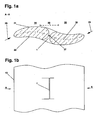
- a profile shown as profile section is a point of symmetry 27 point-symmetrical applied overflow device 1 before.
- the overflow device 1 breaks through the profile in a central region 26, which is defined as that profile part, which ranges from 3/8 to 5/8 of the tread depth.
- the overflow device 1 can according to a first embodiment extend longitudinally over the entire turbine blade 13, so that there is a divided over the entire longitudinal extent profile. According to an alternative embodiment shown here, the overflow device 1 extends over a limited section of the longitudinal extension of the turbine blade 13 FIG. 1b outlines a plan view of the turbine blade 13 with the in FIG. 1a shown profile according to the invention. In this case, a plurality of overflow devices 1 can be provided along the turbine blade 13, which are separated from each other by the structural stability improving transverse webs. This is not shown in detail in the figures.
- the effect of an overflow device 1 for a point-symmetrical, bidirectionally impinged S-impact profile is the following:
- the main buoyancy effect is for the first inflow direction 28 through the front profile part, i. the first profile half 24 causes. Accordingly, for an opposite direction of flow, i. in the direction of the second flow direction 29, the essential effect of the profile through the second profile half 25, which then lies upstream.
- the overflow device 1 causes an overflow from the pressure side to the downstream region of the opposite profile side.
- part of the profile flow along the first profile half 24 on the second profile side 22 is guided via the overflow device 1 to the second profile half 25 of the first profile side 21 and there reduces the risk of flow separation on the one hand and the torsional moment on the turbine blade 13 on the other hand.
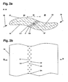
- FIG. 2b is another embodiment, which is not part of the invention, the invention can be seen. Shown is a plurality of overflow channels 2, 2.1, 2.2, ..., 2.n to Forming the overflow opening 1.
- the individual transfer channels 2, 2.1, 2.2, ..., 2.n over the longitudinal extent of the turbine blade 13 parallel and offset from one another. Embodiments are also conceivable for which adjacent channels are oriented in an angular position or provided with branches.
- the cross sections of the overflow 2, 2.1, 2.2, ..., 2.n can be changed.
- Preferred is an alternative embodiment with slit-shaped overflow channels 2, 2.1, 2.2, ..., 2.n. Such embodiments are not shown in detail in the figures.
- FIGS. 3a and 3b an embodiment of the invention is shown.
- the profile section CC in FIG. 3a shows a first eccentric flow channel 5 and a second eccentric flow channel 6, which are arranged at least over parts of their extension outside the central region 26.
- the first channel closure elements 7.1 and 7.2 are provided for closing the first off-center overflow channel 5.
- the first inflow direction 28 are closed so that no overflow from the first profile side 21 to the second profile side 22 occurs through the first eccentric overflow channel 5 and thus in the region of the first profile half 24.
- the case for the second off-center overflow channel 6 is different here.
- the assigned second channel closure elements 10.1, 10.2 are opened for the first inflow direction 28 shown, so that the desired overflow from the first profile side 21 to the second profile side 22 results in the second profile half.
- a passive control of the first and second channel closure elements 7.1, 7.2, 10.1, 10.2 is effected.
- a first elastic profiled element 8 which comprises a pressure-absorbing working medium, is compressed for the first inflow direction 28 shown, wherein a connection between the first channel closure elements 7.1, 7.2 and the first elastic profiled element 8 is provided via the first coupling channel 9.
- a compression of the first elastic profile element 8 due to its pressure side position for the first direction of flow 28 to Another is the case for the second elastic profile element 11, which is point symmetrical relative to the symmetrical point 27 to the first elastic profile element 8 and thus for the first Flow direction 28 is suction side.
- the second channel closure elements 10.1, 10.2 are retracted via the second coupling channel 12 due to the fluidic coupling and released against the second off-center flow channel 6.
- the first elastic profile element 8 is on the suction side and the second elastic profile element 11 on the pressure side, whereby the first channel closure elements 7.1, 7.2 release the first off-center overflow channel 5 and the second channel closure elements 10.1, 10.2 close the second off-center overflow channel 6.
- FIG. 3b is a plan view of a turbine blade 13 with a profile according to FIG. 3a shown. It can be seen that the first elastic profiled elements 8, 8.1,..., 8.n, which are each assigned to a first off-center overflow channel 5, 5.1,..., 5.n, have a limited extent in turbine blade longitudinal direction, to avoid a transport of the working medium under centrifugal force.
- an adaptive adaptation of the profile was carried out as a function of the inflow direction. This is understood to mean a refraction of the point symmetry caused by deformation of the profile, wherein the direction of deformation reverses when the direction of flow changes.
- FIGS. 4a and 4b show a further alternative embodiment which is not part of the invention, for which a first adaptive wall element 3 and a second adaptive wall element 4 for a further embodiment of a FIG. 1a corresponding overflow device 1 are provided.
- the first adaptive wall element 3 is arranged in that part of the overflow device 1, the first profile half 24 is assigned to the first profile page 21.
- the second adaptive wall element 4 is associated with the second profile half 25 on the second profile side 22.
- the passive adjustment of the contour of the first and second adaptive wall elements 3, 4 is shown, which are designed as elastic components or have a flowable or compressible filling. Due to the deformation of the adaptive wall elements 3, 4, a symmetry breaking of the contour of the overflow device 1, which effects an improvement of the flow guidance in the overflow device 1, occurs when the profile is incident on the profile. However, the basic contour of the profile, ie the state without incident flow, is unchanged point-symmetrical to the symmetry point 27.
- FIGS. 5a and 5b For example, a design alternative having a first active adaptive wall element 16 and a second active adaptive wall element 17 is shown.
- the first active, adaptive wall element 16 of the first profile half 24 of the first profile side 21 is assigned and the second active, adaptive wall element 17 is part of the second profile half 25 on the second profile side 22.
- the first adaptive wall elements 16 is associated with a first actuator 18, which may for example comprise a hydraulic cylinder.
- a second actuator 19 and a second pivot point 15 are associated with the second adaptive wall elements 17.
- the second active adaptive wall element 17 is extended and corrects the overall contour of the second profile half 25.
- the first active, adaptive Wall element 16 remains in the retracted state.
- the first active adaptive wall element 16 is correspondingly extended and corrects the associated profile area.
- the second active, adaptive wall element 17 will remain in its original state. This situation is in FIG. 5b shown.
- the embodiment according to the FIGS. 5a and 5b uses actively tracked adaptive elements in the region of the overflow device 1 according to the invention, wherein compared to a purely passive system, an increased expenditure on equipment for the control is necessary.
- active devices for adaptation to a flow direction change by means of a full rotation of the turbine blade 13 by a mounted at the interface to the hub pitch adjustment there is the advantage that by a plurality of separately switchable, adaptive elements an inflow direction adjustment of the profile contour can be effected, can be distributed for the flow forces on several individual components.
- the failure of individual adaptive elements does not lead to a complete loss of function of the turbine blade 13.
- a channel structure with an inlet opening in the region of a profile nose can be created, which displaces flow components along the skeleton line within the profile up to an outlet opening in the region of a profile section lying downstream and on the suction side.
Landscapes
- Engineering & Computer Science (AREA)
- Chemical & Material Sciences (AREA)
- Combustion & Propulsion (AREA)
- Mechanical Engineering (AREA)
- General Engineering & Computer Science (AREA)
- Other Liquid Machine Or Engine Such As Wave Power Use (AREA)
- Hydraulic Turbines (AREA)
Description
- Die Erfindung betrifft ein bidirektional anströmbares Turbinenblatt, für eine Wasserturbine, die bevorzugt in einer tauchenden Energieerzeugungsanlage für die Energiegewinnung aus einer bidirektionalen Wasserströmung verwendet wird.
- Zur Energiegewinnung aus einer richtungsvariablen Strömung, beispielsweise einer Gezeitenströmung, mittels einer freistehenden, propellerförmig gestalteten Turbine wird üblicherweise ein Nachführmechanismus verwendet, der eine Gondel mit der daran angebrachten Turbine in die Strömung dreht. Liegen im Wesentlichen zwei entgegengesetzt gerichtete Haupanströmungsrichtungen, wie bei Ebbe und Flut in einer Gezeitenströmung, vor, so kann eine solche Richtungsnachführung durch eine Klapp- oder Drehvorrichtung realisiert werden, die die Gondel von einer ersten in eine zweite Stellung schwenkt. Nachteilig ist jedoch, dass für einen derartigen Nachführmechanismus massive Dreh- oder Klappscharniersysteme verwendet werden müssen. Darüber hinaus ist für den Fall, dass die Wasserturbine einen elektrischen Generator antreibt, eine Vorrichtung vorzusehen, die ein Verdrillen des vom elektrischen Generator ausgehenden Leistungskabels verhindert.
- Zur Umgehung dieser Problematik kann anstatt einer Gesamtnachführung der Wasserturbine mittels einer Pitch-Verstelleinrichtung, die eine Drehung der Turbinenblätter um 180° an der Nabe realisiert, eine Vorrichtung zur bidirektionalen Anströmung geschaffen werden. Allerdings ist auch eine solche Ausgestaltung mit Nachteilen verbunden, da für eine propellerförmige Turbine mit radial nach außen gerichteten Turbinenblättern typischerweise wenigstens für eine Anströmungsrichtung die Haltestrukturen der Gondel luvseitig liegen, sodass ein den Wirkungsgrad reduzierendes Strömungshindernis vorliegt. Darüber hinaus ist ein Pitch-Verstellungsmechanismus konstruktiv aufwendig und für tauchende Energieerzeugungsanlagen zur Entnahme von Energie aus einer Meeresströmung im Hinblick auf die Notwendigkeit zur Wartung von Nachteil.
- Als weitere Alternative zur Schaffung einer bidirektional anströmbaren Wasserturbine wurde in der
WO 2006/125959 A1 vorgeschlagen, als Profilkontur für die Turbinenblätter einer rotorförmigen Wasserturbine ein doppelt symmetrisches Profil zu wählen. Dabei stellt eine erste Symmetrieachse die Sehnenlinie dar. Zusätzlich ist das Profil zu einer Mittenlinie symmetrisch, die als Lotrechte auf der Profilsehne bei 50 % der Sehnenlänge definiert ist. Als Folge ergibt sich ein linsenförmiges Profil, das für eine bidirektionale Anströmung jeweils identische Profilkonturen sicherstellt. Nachteilig ist jedoch, dass aufgrund der doppelt gewählten Symmetrie für die Profilkontur im Vergleich zu einem einseitig angeströmten, gewölbten Profil ein geringerer Wirkungsgrad resultiert. Ferner ergeben sich Nachteile aufgrund abstromseitiger Strömungsablösungen und einem erhöhten Strömungswiderstand der Turbinenblätter. - Ferner sind aus der Druckschrift
US 2007/0231148 A1 punktsymmetrische Profile mit einer Wölbung bekannt. Diese zeichnen sich durch einen Symmetriepunkt aus, der bei halber Profiltiefe auf der Profilsehne liegt, sodass die punktsymmetrisch gestaltete Skelettlinie einen S-Schlag vollzieht. Die Dickenverteilung des Profils ist symmetrisch zur Mittenlinie gewählt. Dabei verbessert das S-Schlag-förmige Profil die Leistungsbeiwerte und verringert die Schubbeiwerte. - Der Erfindung liegt die Aufgabe zugrunde, ein Turbinenblatt so zu gestalten, dass eine bidirektionale Anströmung möglich ist. Dieses Turbinenblatt soll dazu geeignet sein, für eine propellerförmige Turbine einer tauchenden Energieerzeugungsanlage verwendet zu werden, wobei sich das Turbinenblatt durch einen hohen Wirkungsgrad und geringe Längsverwindung für eine Anströmung aus beiden Richtungen auszeichnen soll.
- Die Erfindung baut auf den bekannten punktsymmetrischen Profilen mit einer S-Schlag-förmigen Skelettlinie und einer zur Mittenlinie des Profils symmetrischen Dickenverteilung auf. Dieses Profil wird nunmehr derart weitergestaltet, dass eine Überströmvorrichtung von einer ersten Profilseite zu einer zweiten Profilseite gegeben ist.
- Aufgrund der punktsymmetrischen Profilform besteht für S-Schlag-Profile die Gefahr einer Strömungsablösung auf den abstromseitigen Profilteilen. Ferner wirken starke Torsionskräfte auf ein Turbinenblatt mit einem solchen Profil. Durch ein Überströmen von der der ersten zur zweiten Profilseite im Mittelteil und/oder dem abstromseitigen Bereich des Profils besteht die Möglichkeit, die Tendenz zu Strömungsablösungen zu verringern und aufgrund der verringerten Torsionskräfte die Turbinenblattaussteifung gegen ein Verdrillen konstruktiv zu vereinfachen.
- Des Weiteren kann das Turbinenblattprofil im Wesentlichen an die strömungstechnischen Gegebenheiten angepasst werden, ohne konkurrierenden strukturmechanischen Anforderungen bei der Konstruktion des Turbinenblatts folgen zu müssen. Dabei können insbesondere langgestreckte, schlanke Profile verwendet werden, die zu einer hohen Gleitzahl führen. Ferner müssen die Befestigungen des Turbinenblatts an der Nabe der umlaufenden Einheit verringerte Drehmomente aufnehmen und können entsprechend konstruktiv und fertigungstechnisch vereinfacht werden.
- Gemäß der vorliegenden Erfindung umfasst die Überströmvorrichtung eine Vielzahl von Überströmkanälen, deren Orientierung an die bidirektionale Anströmungsrichtung angepasst ist. Für eine weitere Ausführungsvariante, die alternativ oder zusätzlich zu den Überströmkanälen anwendbar ist, wird die Überströmvorrichtung durch ein geteiltes Blattprofil gebildet. Hierbei liegt im Mittelbereich des Gesamtprofils wenigstens ein Teilabschnitt vor, für den die Dickenverteilung entlang der S-Schlag-förmigen Skelettlinie den Wert Null annimmt.
- Die Überströmvorrichtung der Erfindung umfasst Überströmkanäle, die in Abhängigkeit der Anströmungsrichtung verschließbar sind. Damit können Überströmkanäle auch außerhalb des Mittelbereichs des Profils angeordnet werden. Das Verschließen der Überströmkanäle kann passiv oder aktiv bewirkt werden. Für eine passive Ausführung besteht bevorzugt eine Kopplung von Kanalverschlusselementen in den Überströmkanälen mit elastischen Profilelementen, die entlang der von der Strömung überstrichenen Außenseite des Profils angeordnet sind und durch die Strömungskräfte deformiert werden. Wird in den elastischen Profilelementen ein hydraulisches oder pneumatisches Arbeitsmedium aufgenommen, können so Druckkräfte zur Aktorik der Kanalverschlusselemente generiert und gleichzeitig ein adaptives Profil geschaffen werden.
- Für eine Weitergestaltung kann die Überströmvorrichtung adaptive Wandungselemente umfassen, die in Abhängigkeit der Anströmungsrichtung von einer ersten in eine zweite Stellung wechseln und so Abweichungen zur Punktsymmetrie des Profils bewirken. Hierdurch kann ein gezieltes Überströmen zum hinteren, abstromseitigen Bereich des Profils bewirkt werden, ohne dass ein gravierender Wirkungsgradverlust auftritt. Dabei können die adaptiven Wandungselemente durch eine zugeordnete Aktorik entweder aktiv verstellt werden oder diese sind als passive, elastische Komponenten ausgebildet, deren Kontur sich mit der Anströmung ändert.
- Nachfolgend wird die Erfindung anhand von Ausführungsbeispielen in Verbindung mit den Figurendarstellungen genauer erläutert, in denen im Einzelnen Folgendes dargestellt ist:
- Figur 1a
- zeigt einen Profilschnitt entlang der Linie A-A aus
Figur 1b für ein punktsymmetrisches Profil mit einer Überströmvorrichtung von der ersten zur zweiten Profilseite. - Figur 1b
- zeigt einen Teilabschnitt eines Turbinenblatts in Draufsicht für das Profil aus
Figur 1 a mit einer im Mittelbereich des Profils angelegten Überströmvorrichtung mit begrenzter Erstreckung in Längsrichtung des Turbinenblatts. - Figur 2a
- zeigt als Profilschnitt ein alternatives Ausführungsbeispiel welches nicht Teil der Erfindung ist, mit einer Vielzahl von Überströmkanälen.
- Figur 2b
- zeigt eine Draufsicht auf einen Teilabschnitt eines Turbinenblatts mit einem Profil gemäß
Figur 2a . - Figur 3a
- zeigt einen erfindungsgemäßen Profilschnitt mit außermittig angelegten, passiv ansteuerbaren Überströmkanälen.
- Figur 3b
- zeigt eine Draufsicht auf einen Teilabschnitt eines Turbinenblatts mit einem Profil gemäß
Figur 3a . - Figuren 4a und 4b
- zeigen eine Weitergestaltung welche nicht Teil der Erfindung ist, mit einer paarweisen und punktsymmetrischen Anordnung elastischer Elemente zur Profilbeeinflussung in der Überströmvorrichtung von der ersten Profilseite zur zweiten Profilseite.
- Figuren 5a und 5b
- zeigen aktive, adaptive Wandungselemente in der Überströmvorrichtung in unterschiedlichen Stellungen für die erste und die zweite Anströmungsrichtung.
- Figur 6
- zeigt ein dem Stand der Technik entsprechendes punktsymmetrisches, gewölbtes Profil zur Ausbildung eines bidirektional anströmbaren Turbinenblatts.
- Zur Darlegung der im Folgenden verwendeten Begrifflichkeit wird zunächst ein dem Stand der Technik entsprechender, in
Figur 6 dargestellter Profilschnitt betrachtet. Gezeigt ist ein Profil, das punktsymmetrisch zum Symmetriepunkt 27 ausgebildet ist. Dabei ist der Symmetriepunkt 27 bei halber Profiltiefe auf der Profilsehne 20 angeordnet und liegt demnach deckungsgleich zum Schnittpunkt der Profilsehne 20 mit der Mittenlinie 23, wobei letztere als senkrecht zur Profilsehne 20 verlaufend definiert ist. - Für das dargestellte S-Schlag-förmige Profil weist die zum Symmetriepunkt 27 punktsymmetrisch angelegte Skelettlinie 32 eine Wölbung w auf. Des Weiteren führt die voranstehend genannte Symmetriebedingung zu einer bezüglich der Mittenlinie 23 symmetrisch angelegten Profildickenverteilung. Andere Ausführungsformen für bidirektional anströmbare, punktsymmetrische Profile sind denkbar (nicht dargestellt), etwa eine Skelettlinie mit wenigstens einem abschnittsweise linearen Verlauf im mittleren Profilabschnitt und punktsymmetrisch zueinander gestalteten Profilnasen 30, 31.
- Für die nachfolgende Darlegung wird begrifflich von einer Teilung des Profils durch die Skelettlinie 32 ausgegangen, die zu einer ersten Profilseite 21 und einer zweiten Profilseite 22 führt. Des Weiteren soll durch die Mittenlinie 23 eine Aufteilung des Profils in eine erste Profilhälfte 24 und eine zweite Profilhälfte 25 gegeben sein. Dabei reicht die erste Profilhälfte 24 von der ersten Profilnase 30 bis zur Mittenlinie 23 und die zweite Profilhälfte 25 entsprechend von der Mittenlinie 23 bis zur zweiten Profilnase 31.
- Ferner entsteht für die skizzierte erste Anströmungsrichtung 28, wobei von einer effektiven Anströmung ausgegangen wird, wenigstens in der ersten Profilhälfte 24 auf der ersten Profilseite 21 eine Saugwirkung und auf der zweiten Profilseite 22 eine Druckwirkung. Allerdings kann aufgrund des S-Schlags im Bereich der abstromseitigen Kante der zweiten Profilhälfte 25 auf der ersten Profilseite 21, d.h. in der Nähe zweiten Profilnase 31, für die betrachtete erste Anströmungsrichtung 28 ein Druckbauch entstehen, der die Effizienz des Profils verringert und die auf das S-Schlagprofil wirkenden Torsionskräfte weiter erhöht. Für die zweite Anströmungsrichtung 29 ist die druck- und saugseitige Zuordnung entsprechend am Symmetriepunkt 27 gespiegelt.
- Für das in
Figur 1 a als Profilschnitt dargestellte Profil liegt eine zum Symmetriepunkt 27 punktsymmetrisch angelegte Überströmvorrichtung 1 vor. Für das dargestellt Ausgestaltungsbeispiel durchbricht die Überströmvorrichtung 1 das Profil in einem Mittelbereich 26, der als jener Profilteil definiert ist, der von 3/8 bis zu 5/8 der Profiltiefe reicht. - Die Überströmvorrichtung 1 kann gemäß einer ersten Ausgestaltung längs über das gesamte Turbinenblatt 13 reichen, sodass ein über die gesamte Längserstreckung geteiltes Profil vorliegt. Gemäß einer alternativen, vorliegend dargestellten Ausgestaltung erstreckt sich die Überströmvorrichtung 1 über einen begrenzten Abschnitt der Längserstreckung des Turbinenblatts 13. Diese Ausführung ist in
Figur 1b skizziert, die eine Draufsicht auf das Turbinenblatt 13 mit dem inFigur 1a gezeigten erfindungsgemäßen Profil darstellt. Dabei können längs des Turbinenblatts 13 mehrere Überströmvorrichtungen 1 vorgesehen sein, die jeweils durch die Strukturstabilität verbessernde Querstege voneinander getrennt sind. Dies ist im Einzelnen nicht in den Figuren dargestellt. - Die Wirkung einer Überströmvorrichtung 1 für ein punktsymmetrisches, bidirektional angeströmtes S-Schlagprofil ist folgende: Die wesentliche Auftriebswirkung wird für die erste Anströmungsrichtung 28 durch den vorderen Profilteil, d.h. der ersten Profilhälfte 24, bewirkt. Entsprechend ergibt sich für eine entgegengesetzte Anströmungsrichtung, d.h. in Richtung der zweiten Anströmungsrichtung 29, die wesentliche Wirkung des Profils durch die zweite Profilhälfte 25, die dann stromaufwärts liegt. Durch die Überströmvorrichtung 1 wird ein Überströmen von der Druckseite zum abstromseitigen Bereich der gegenüberliegenden Profilseite bewirkt. Demnach wird für die erste Anströmungsrichtung 28 ein Teil der Profilumströmung entlang der ersten Profilhälfte 24 auf der zweiten Profilseite 22 über die Überströmvorrichtung 1 zur zweiten Profilhälfte 25 der ersten Profilseite 21 geführt und verringert dort die Gefahr von Strömungsablösungen zum einen und das Torsionsmoment auf das Turbinenblatt 13 zum anderen.
- Aus dem in
Figur 2a dargestellten Profilschnitt entlang der Schnittlinie B-B ausFigur 2b ist ein weiteres Ausgestaltungsbeispiel, welches nicht Teil der Erfindung ist, der Erfindung ersichtlich. Dargestellt ist eine Vielzahl von Überströmkanälen 2, 2.1, 2.2, ..., 2.n zur Ausbildung der Überströmungsöffnung 1. GemäßFigur 2b sind die einzelnen Überströmkanäle 2, 2.1, 2.2, ..., 2.n über die Längserstreckung des Turbinenblatts 13 parallel und versetzt zueinander angeordnet. Dabei sind auch Ausgestaltungen denkbar, für die benachbarte Kanäle in einer Winkelstellung orientiert oder mit Verzweigungen versehen sind. Außerdem können die Querschnitte der Überströmkanäle 2, 2.1, 2.2, ..., 2.n verändert werden. Bevorzugt wird eine Ausführungsalternative mit schlitzförmigen Überströmkanälen 2, 2.1, 2.2, ..., 2.n. Derartige Ausführungsformen sind im Einzelnen nicht in den Figuren dargestellt. - In den
Figuren 3a und 3b ist eine Ausgestaltung der Erfindung dargestellt. Der Profilschnitt C-C inFigur 3a zeigt einen ersten außermittigen Strömungskanal 5 und einen zweiten außermittigen Strömungskanal 6, die wenigstens über Teile ihrer Erstreckung außerhalb des Mittelbereichs 26 angeordnet sind. Zum Verschluss des ersten außermittigen Überströmkanals 5 sind die ersten Kanalverschlusselemente 7.1 und 7.2 vorgesehen. Für die skizzierte erste Anströmungsrichtung 28 sind diese geschlossen, sodass durch den ersten außermittigen Überströmkanal 5 und damit im Bereich der ersten Profilhälfte 24 kein Überströmen von der ersten Profilseite 21 zur zweiten Profilseite 22 auftritt. Anders liegt der Fall für den zweiten außermittigen Überströmkanal 6. Hier sind für die gezeigte erste Anströmungsrichtung 28 die zugeordneten zweiten Kanalverschlusselemente 10.1, 10.2 geöffnet, sodass in der zweiten Profilhälfte das erwünschte Überströmen von der ersten Profilseite 21 zur zweiten Profilseite 22 resultiert. - Für die dargestellte Ausgestaltung wird eine passive Ansteuerung der ersten und zweiten Kanalverschlusselemente 7.1, 7.2, 10.1, 10.2 bewirkt. Dabei wird ein erstes elastisches Profilelement 8, das ein druckaufnehmendes Arbeitsmedium umfasst, für die gezeigte erste Anströmungsrichtung 28 komprimiert, wobei eine Verbindung zwischen den ersten Kanalverschlusselementen 7.1, 7.2 und dem ersten elastischen Profilelement 8 über den ersten Kopplungskanal 9 gegeben ist. Entsprechend führt eine Komprimierung des ersten elastischen Profilelements 8 aufgrund dessen druckseitiger Lage für die erste Anströmungsrichtung 28 zu einem Entfalten der balgförmig angelegten ersten Kanalverschlusselemente 7.1, 7.2 und damit zu der voranstehend genannten Strömungsunterbrechung im ersten außermittigen Überströmkanal 5. Anders liegt der Fall für das zweite elastische Profilelement 11, das relativ zum Symmetriepunkt 27 punktsymmetrisch zum ersten elastischen Profilelement 8 und damit für die erste Anströmungsrichtung 28 saugseitig liegt. Entsprechend werden die zweite Kanalverschlusselemente 10.1, 10.2 aufgrund der fluidischen Kupplung über den zweiten Kopplungskanal 12 eingefahren und gegen den zweiten außermittigen Strömungskanal 6 frei. Für die nicht dargestellte zweite Strömungsrichtung 29 liegt das erste elastische Profilelement 8 saugseitig und das zweite elastische Profilelement 11 druckseitig, wodurch die ersten Kanalverschlusselemente 7.1, 7.2 den ersten außermittigen Überströmkanal 5 freigeben und die zweiten Kanalverschlusselemente 10.1, 10.2 den zweiten außermittigen Überströmkanal 6 schließen.
- In
Figur 3b wird eine Draufsicht auf ein Turbinenblatt 13 mit einem Profil gemäßFigur 3a gezeigt. Es ist ersichtlich, dass die ersten elastischen Profilelemente 8, 8.1, ..., 8.n, die jeweils einem erstem außermittigen Überströmkanal 5, 5.1, ..., 5.n zugeordnet sind, eine begrenzte Erstreckung in Turbinenblatt-Längsrichtung aufweisen, um eine Verfrachtung des Arbeitsmediums unter Fliehkraftwirkung zu vermeiden. - Durch die von den Strömungskräften bewirkte Verformung der elastischen Profilelemente 8, 8.1, 8.n, 11 erfolgte eine adaptive Anpassung des Profils in Abhängigkeit der Anströmungsrichtung. Hierunter wird eine durch Verformung des Profils bewirkte Brechung der Punktsymmetrie verstanden, wobei sich beim Wechsel der Anströmungsrichtung die Verformungsrichtung umkehrt.
-
Figuren 4a und 4b zeigen eine weitere Ausgestaltungsalternative welche nicht Teil der Erfindung ist, für die ein erstes adaptives Wandungselement 3 und ein zweites adaptives Wandungselement 4 für eine Weitergestaltung einerFigur 1a entsprechenden Überströmvorrichtung 1 vorgesehen sind. Dabei ist das erste adaptive Wandungselement 3 in jenem Teil der Überströmvorrichtung 1 angeordnet, der der ersten Profilhälfte 24 auf der ersten Profilseite 21 zugeordnet ist. Hierzu punktsymmetrisch zum Symmetriepunkt 27 liegt das zweite adaptive Wandungselement 4, das der zweiten Profilhälfte 25 auf der zweiten Profilseite 22 zugeordnet ist. - In den
Figuren 4a und 4b ist die passive Einstellung der Kontur des ersten und des zweiten adaptiven Wandungselements 3, 4 gezeigt, die als elastische Komponenten ausgebildet sind oder eine strömungsfähige oder komprimierbare Füllung aufweisen. Aufgrund der Deformation der adaptiven Wandungselemente 3, 4 entsteht bei einer Anströmung auf das Profil eine Symmetriebrechung der Kontur der Überströmvorrichtung 1, die eine Verbesserung der Strömungsführung in der Überströmvorrichtung 1 bewirkt. Die Grundkontur des Profils, d.h. der Zustand ohne Anströmung, ist jedoch unverändert punktsymmetrisch zum Symmetriepunkt 27. - In den
Figuren 5a und 5b ist eine Ausgestaltungsalternative mit einem ersten aktiven, adaptiven Wandungselement 16 und einem zweiten aktiven, adaptiven Wandungselement 17 gezeigt. Dabei ist das erste aktive, adaptive Wandungselement 16 der ersten Profilhälfte 24 der ersten Profilseite 21 zugeordnet und das zweite aktive, adaptive Wandungselement 17 ist Teil der zweiten Profilhälfte 25 auf der zweiten Profilseite 22. Zur Ausführung Drehbewegung um einen ersten Drehpunkt 14, der nahe des äußeren Rands der Überströmvorrichtung 1 liegt, ist dem ersten adaptiven Wandungselemente 16 ein erster Aktor 18 zugeordnet, der beispielsweise einen Hydraulikzylinder umfassen kann. Für kleine Stellbewegungen können als Aktoren 18 auch Piezoelemente verwendet werden. Entsprechend sind dem zweiten adaptiven Wandungselemente 17 ein zweiter Aktor 19 und ein zweiter Drehpunkt 15 zugeordnet. - Für die in
Figur 5a dargestellte, erste Anströmungsrichtung 28 wird das zweite aktive, adaptive Wandungselement 17 ausgefahren und korrigiert die Gesamtkontur der zweiten Profilhälfte 25. Das erste aktive, adaptive Wandungselement 16 verbleibt im eingefahrenen Zustand. Bei einem Wechsel der Anströmung zur zweiten Anströmungsrichtung 29 wird entsprechend das erste aktive, adaptive Wandungselement 16 ausgefahren und korrigiert den zugehörigen Profilbereich. Auf der Saugseite wird das zweite aktive, adaptive Wandungselement 17 im ursprünglichen Zustand verbleiben. Diese Situation ist inFigur 5b dargestellt. - Die Ausführungsform gemäß der
Figuren 5a und 5b verwendet aktiv nachgeführte adaptive Elemente im Bereich der erfindungsgemäßen Überströmvorrichtung 1, wobei gegenüber einem rein passiven System ein erhöhter apparativer Aufwand für die Ansteuerung notwendig ist. Gegenüber den bisher angewandten, aktiven Vorrichtungen zur Anpassung an einen Anströmungsrichtungswechsel mittels einer Volldrehung des Turbinenblatts 13 durch eine an der Schnittstelle zur Nabe angebrachte Pitch-Verstellvorrichtung ergibt sich der Vorteil, dass durch eine Vielzahl von separat schaltbaren, adaptiven Elementen eine Anströmungsrichtungs-Anpassung der Profilkontur bewirkt werden kann, für die Strömungskräfte auf mehrere Einzelkomponenten verteilbar sind. Außerdem führt der Ausfall einzelner adaptiver Elemente nicht zu einem kompletten Funktionsverlust des Turbinenblatts 13. - Weitere Ausgestaltungen der Erfindung sind denkbar. So kann beispielsweise innerhalb des Profils eine Kanalstruktur mit einer Eintrittsöffnung im Bereich einer Profilnase angelegt werden, die Strömungsanteile längs der Skelettlinie innerhalb des Profils bis zu einer Austrittsöffnung im Bereich eines abstrom- und saugseitig liegenden Profilabschnitts verlagert. Weitere Ausgestaltungsvarianten ergeben sich aus dem anschließenden Schutzansprüchen.
-
- 1
- Überströmvorrichtung
- 2, 2.1, 2.2, 2.m
- Überströmkanal
- 3
- erstes adaptives Wandungselement
- 4
- zweites adaptives Wandungselement
- 5, 5.1, ..., 5.n
- erster außermittiger Überströmkanal
- 6, 6.1, ..., 6.n
- zweiter außermittiger Überströmkanal
- 7.1, 7.2
- erstes Kanalverschlusselement
- 8, 8.1, ..., 8.n
- erstes elastisches Profilelement
- 9
- erster Kopplungskanal
- 10.1, 10.2
- zweites Kanalverschlusselement
- 11
- zweites elastisches Profilelement
- 12
- zweiter Kopplungskanal
- 13
- Turbinenblatt
- 14
- erster Drehpunkt
- 15
- zweiter Drehpunkt
- 16
- erstes aktives, adaptives Wandungselement
- 17
- zweites aktives, adaptives Wandungselement
- 18
- erster Aktor
- 19
- zweiter Aktor
- 20
- Profilsehne
- 21
- erste Profilseite
- 22
- zweite Profilseite
- 23
- Mittenlinie
- 24
- erste Profilhälfte
- 25
- zweite Profilhälfte
- 26
- Mittelbereich
- 27
- Symmetriepunkt
- 28
- erste Anströmungsrichtung
- 29
- zweite Anströmungsrichtung
- 30
- erste Profilnase
- 31
- zweite Profilnase
- 32
- Skelettlinie
- w
- Wölbung
Claims (7)
- Turbinenblatt für eine Wasserturbine, das wenigstens in einem Teilbereich seiner Längserstreckung ein gewölbtes Profil mit einer Skelettlinie (32) aufweist, die punktsymmetrisch zu einem, bei halber Profiltiefe auf der Profilsehne (20) liegenden Symmetriepunkt (27) ausgebildet ist und einen S-Schlag ausführt, wobei die Skelettlinie (32) das Profil in eine erste Profilseite (21) und eine zweite Profilseite (22) aufteilt; und
wobei das Profil eine Mittenlinie (23) umfasst, die eine Lotrechte auf der Profilsehne (20) mit dem Symmetriepunkt (27) als Fußpunkt darstellt und die das Profil in eine erste Profilhälfte (24) und in eine zweite Profilhälfte (25) aufteilt;
dadurch gekennzeichnet, dass
das Turbinenblatt eine Überströmvorrichtung (1) umfasst, die eine fluidische Verbindung zwischen der ersten Profilseite (21) und der zweiten Profilseite (22) herstellt, wobei die Überströmvorrichtung (1) einen ersten außermittigen Überströmkanal (5, 5.1, .., 5.n), der eine fluidische Verbindung zwischen der ersten Profilseite (21) und der zweiten Profilseite (22) In der ersten Profilhälfte (24) herstellt, und einen zweiten außermittigen Überströmkanal (6, 6.1, ..., 6.n), der eine fluidische Verbindung zwischen der ersten Profilseite (21) und der zweiten Profilseite (22) in der zweiten Profilhälfte (25) herstellt, umfasst; und
dem ersten außermittigen Überströmkanal (5, 5.1, ..., 5.n) ein erstes Kanalverschlusselement (7.1, 7.2) und dem zweiten außermittigen Überströmkanal (6, 6.1, ..., 6.n) ein zweites Kanalverschlusselement (10.1, 10.2) zugeordnet sind, die für den selektiven Verschluss des jeweiligen außermittigen Überströmkanals in Abhängigkeit der Anströmungsrichtung ausgelegt sind. - Turbinenblatt nach Anspruch 1, dadurch gekennzeichnet, dass das selektive Verschließen des ersten außermittigen Überströmkanals (5, 5.1, ..., 5.n) und des zweiten außermittigen Überströmkanals (6, 6.1, ..., 6.n) passiv bewirkt wird.
- Turbinenblatt nach Anspruch 2, dadurch gekennzeichnet dass zur passiven Ansteuerung des ersten Kanalverschlusselements (7, 7.1, 7.2) ein erstes elastisches Profilelement (8, 8.1, ..., 8.n) auf der zweiten Profilseite (22) und zur passiven Ansteuerung des zweiten Kanalverschlusselements (10.1, 10.2) ein zweites elastisches Profilelement (11) auf der ersten Profilseite (21) verwendet wird.
- Turbinenblatt nach einem der vorausgehenden Ansprüche, dadurch gekennzeichnet, dass die Überströmvorrichtung (1) ein erstes adaptives Wandungselement (3) und ein zweites adaptives Wandungselement (4), die symmetrisch zum Symmetriepunkt (27) angeordnet sind, umfasst.
- Turbinenblatt nach Anspruch 4, dadurch gekennzeichnet, dass das erste adaptive Wandungselement (3) und das zweite adaptive Wandungselement (4) als passive Elemente wirken, deren Kontur von den Strömungskräften beeinflusst wird.
- Turbinenblatt nach Anspruch 4, dadurch gekennzeichnet, dass das erste adaptive Wandungselement (3) ein erstes aktives, adaptives Wandungselement (16) umfasst und das zweite adaptive Wandungselement (4) ein zweites aktives, adaptives Wandungselement (17) umfasst.
- Verfahren zum Betrieb eines Turbinenblatts für eine bidirektional anströmbare Wasserturbine, das wenigstens in einem Teilbereich seiner Längserstreckung ein gewölbtes Profil mit einer Skelettlinie (32) aufweist, die punktsymmetrisch zu einem, bei halber Profiltiefe auf der Profilsehne (20) liegenden Symmetriepunkt (27) ausgebildet ist und einen S-Schlag ausführt, wobei die Skelettlinie (32) das Profil in eine erste Profilseite (21) und eine zweite Profilseite (22) aufteilt; und
wobei das Profil eine Mittellinie (23) umfasst, die eine letrechte auf der Profilsehne (20) mite dem Symmetriepunkt (27) als Tußpunkt darstellt und die das Profil in eine erste Profilhälfte (24) und in eine inierte Profilhälfte (25) aufteilt,
das Turbinenblatt eine Überströmvorrichtung (1) umfasst die eine fluidische Verbindung zwischen der ersten Profilseite (21) und der zweiten Profilseite (22) herstellt, wobei die Überströmvorrichtung (1) einen ersten außermittigen Überströmkanal (5, 5.1, .., 5.n), der eine fluidische Verbindung zwischen der ersten Profilseite (21) und der zweiten Profilseite (22) in der ersten Profilhälfte (24) herstellt, und einen zweiten außermittigen Überströmkanal (6, 6.1,..., 6.n), der eine fluidische Verbindung zwischen der ersten Profilseite (21) und der zweiten Profilseite (22) in der zweiten Profilhälfte (24) herstellt, umfasst; und wobei der erste außermittige Überströmkanal (5, 5.1, ..., 5.n) ein erstes Kanalverschlusselement (7.1, 7.2) und der zweite außermittige Überströmkanal (6, 6.1, ..., 6.n) ein zweites Kanalverschlusselement (10.1, 10.2) umfassen; und
wobei durch das jeweils zugeordnete Kanalverschlusselement in Abhängigkeit der Anströmungsrichtung der stromaufwärts liegende außermittige Überströmkanal geschlossen und der stromabwärts liegende außermittige Überströmkanal geöffnet wird.
Applications Claiming Priority (2)
| Application Number | Priority Date | Filing Date | Title |
|---|---|---|---|
| DE102009057449A DE102009057449B3 (de) | 2009-12-09 | 2009-12-09 | Turbinenblatt für eine bidirektional anströmbare Wasserturbine |
| PCT/EP2010/007307 WO2011069615A1 (de) | 2009-12-09 | 2010-12-02 | Turbinenblatt für eine bidirektional anströmbare wasserturbine |
Publications (2)
| Publication Number | Publication Date |
|---|---|
| EP2510224A1 EP2510224A1 (de) | 2012-10-17 |
| EP2510224B1 true EP2510224B1 (de) | 2015-04-29 |
Family
ID=43799081
Family Applications (1)
| Application Number | Title | Priority Date | Filing Date |
|---|---|---|---|
| EP20100797994 Not-in-force EP2510224B1 (de) | 2009-12-09 | 2010-12-02 | Turbinenblatt für eine bidirektional anströmbare wasserturbine |
Country Status (6)
| Country | Link |
|---|---|
| US (1) | US20120301294A1 (de) |
| EP (1) | EP2510224B1 (de) |
| KR (1) | KR20120103624A (de) |
| CA (1) | CA2783997A1 (de) |
| DE (1) | DE102009057449B3 (de) |
| WO (1) | WO2011069615A1 (de) |
Families Citing this family (5)
| Publication number | Priority date | Publication date | Assignee | Title |
|---|---|---|---|---|
| GB201113694D0 (en) * | 2011-08-09 | 2011-09-21 | Univ Southampton | Turbine generator |
| FR2980244B1 (fr) * | 2011-09-19 | 2014-07-04 | Sabella | Pale d'hydrolienne |
| DE102011117176A1 (de) * | 2011-10-28 | 2013-05-02 | Voith Patent Gmbh | Rotorblatt für eine Wasserturbine, insbesondere für ein Gezeitenkraftwerk, und Verfahren für dessen Betrieb |
| DE102014204593A1 (de) | 2014-03-12 | 2015-04-23 | Voith Patent Gmbh | Horizontalläuferturbine |
| CN117249032B (zh) * | 2023-11-17 | 2024-03-15 | 哈尔滨大电机研究所有限公司 | 一种混流式水泵水轮机波形活动导叶 |
Family Cites Families (9)
| Publication number | Priority date | Publication date | Assignee | Title |
|---|---|---|---|---|
| DE1187559B (de) * | 1961-11-23 | 1965-02-18 | Escher Wyss Gmbh | Laufrad einer Propellerturbine mit einer den zwischen den Schaufeln gelegenen Stroemungsraum umgehenden hydraulischen Verbindung zwischen Druckseite und Saugseite der Schaufelung |
| EP0954450A4 (de) * | 1997-01-24 | 2000-03-22 | California Inst Of Techn | Mikroelektromechanisches ventil |
| US6368059B1 (en) * | 2000-07-28 | 2002-04-09 | Lockheed Martin Corporation | Controlled passive porosity systems to mitigate cavitation |
| GB0510417D0 (en) * | 2005-05-21 | 2005-06-29 | Rotech Holdings Ltd | Improved turbine |
| US20070231148A1 (en) * | 2006-04-03 | 2007-10-04 | Lehoczky Kalman N | Reversing free flow propeller turbine |
| TWI305243B (en) * | 2006-05-22 | 2009-01-11 | Delta Electronics Inc | Assembly of blade units for wind power generation |
| DE102007021213A1 (de) * | 2007-05-07 | 2008-11-20 | Gernot Kloss | Flügelformen zur Leistungssteigerung beidseitig anströmbarer Turbinen für den Luft- und Wassereinsatz |
| DK200800723A (en) * | 2008-05-27 | 2009-11-28 | Fo900 Invest Aps | Wind turbine blade with aerodynamic slit near the root |
| CN101749180B (zh) * | 2008-12-02 | 2012-02-01 | 叶东华 | 垂直轴式风力发电机的叶片 |
-
2009
- 2009-12-09 DE DE102009057449A patent/DE102009057449B3/de not_active Expired - Fee Related
-
2010
- 2010-12-02 WO PCT/EP2010/007307 patent/WO2011069615A1/de not_active Ceased
- 2010-12-02 KR KR1020127014904A patent/KR20120103624A/ko not_active Withdrawn
- 2010-12-02 CA CA2783997A patent/CA2783997A1/en not_active Abandoned
- 2010-12-02 EP EP20100797994 patent/EP2510224B1/de not_active Not-in-force
- 2010-12-02 US US13/513,976 patent/US20120301294A1/en not_active Abandoned
Also Published As
| Publication number | Publication date |
|---|---|
| EP2510224A1 (de) | 2012-10-17 |
| US20120301294A1 (en) | 2012-11-29 |
| KR20120103624A (ko) | 2012-09-19 |
| WO2011069615A4 (de) | 2011-10-13 |
| DE102009057449B3 (de) | 2011-04-21 |
| CA2783997A1 (en) | 2011-06-16 |
| WO2011069615A1 (de) | 2011-06-16 |
Similar Documents
| Publication | Publication Date | Title |
|---|---|---|
| EP2004990B1 (de) | Rotorblatt einer windenergieanlage | |
| EP2254795B1 (de) | Triebwerks-einlaufklappe zur anbringung an dem gehäuse eines lufteinlasses eines flugzeug-triebwerks sowie triebwerk mit einer solchen triebwerks-einlaufklappe und flugzeugsystem | |
| EP2134961B1 (de) | Unterwasserkraftwerk und verfahren zum betrieb eines unterwasserkraftwerks | |
| EP2788618B1 (de) | Hinterkasten, rotorblatt mit hinterkasten und windenergieanlage mit solchem rotorblatt | |
| EP2258943A2 (de) | Profil eines Rotorsblatts einer Windenergieanlage | |
| DE102012109521A1 (de) | Windturbinenrotorblatt mit einer passiv modifizierten Hinterkantenkomponente | |
| EP2623793A1 (de) | Schaufelgitter und Strömungsmaschine | |
| DE102009057449B3 (de) | Turbinenblatt für eine bidirektional anströmbare Wasserturbine | |
| DE102012109171A1 (de) | Windkraftanlagenrotorblatt mit passiv modifizierter Abströmkantenkomponente | |
| EP3755899B1 (de) | Rotorblatt einer windenergieanlage mit einer splitterplatte | |
| EP2570656A1 (de) | Windenergieanlagenrotorblatt mit einer dicken Profilhinterkante | |
| EP2245298A2 (de) | Rotorblattgestaltung für eine wellsturbine | |
| DE10021850A1 (de) | Adaptive Profilierung für Windenergierotoren | |
| EP2978967B1 (de) | Rotorblatt einer windenergieanlage mit winglet | |
| EP3227550B1 (de) | Hydraulische strömungsmaschine | |
| EP2976524B1 (de) | Rotorblatt einer windenergieanlage, windenergieanlage und verfahren zum betreiben einer windenergieanlage | |
| EP2505493A1 (de) | Adaptiver Vorflügel | |
| DE102014204591B3 (de) | Bidirektional anströmbare Horizontalläuferturbine mit passiver Überlastsicherung | |
| WO2009089902A2 (de) | Luftturbine für ein wellenkraftwerk | |
| DE102012102746A1 (de) | Rotorblatt mit adaptivem Vorflügel für eine Windenergieanlage | |
| DE102009018924A1 (de) | Bidirektional anströmbare Turbine | |
| DE102013010379B4 (de) | Schaufelradvorrichtung | |
| EP2574771B1 (de) | Kompressions-turbine | |
| DE102015103601A1 (de) | Tragflügel mit einem Hauptflügel und einem Vorflügel | |
| DE10064912B4 (de) | Rotorblatt für eine Windenergieanlage |
Legal Events
| Date | Code | Title | Description |
|---|---|---|---|
| PUAI | Public reference made under article 153(3) epc to a published international application that has entered the european phase |
Free format text: ORIGINAL CODE: 0009012 |
|
| 17P | Request for examination filed |
Effective date: 20120609 |
|
| AK | Designated contracting states |
Kind code of ref document: A1 Designated state(s): AL AT BE BG CH CY CZ DE DK EE ES FI FR GB GR HR HU IE IS IT LI LT LU LV MC MK MT NL NO PL PT RO RS SE SI SK SM TR |
|
| DAX | Request for extension of the european patent (deleted) | ||
| GRAP | Despatch of communication of intention to grant a patent |
Free format text: ORIGINAL CODE: EPIDOSNIGR1 |
|
| GRAJ | Information related to disapproval of communication of intention to grant by the applicant or resumption of examination proceedings by the epo deleted |
Free format text: ORIGINAL CODE: EPIDOSDIGR1 |
|
| INTG | Intention to grant announced |
Effective date: 20141219 |
|
| GRAP | Despatch of communication of intention to grant a patent |
Free format text: ORIGINAL CODE: EPIDOSNIGR1 |
|
| INTG | Intention to grant announced |
Effective date: 20150115 |
|
| GRAS | Grant fee paid |
Free format text: ORIGINAL CODE: EPIDOSNIGR3 |
|
| GRAA | (expected) grant |
Free format text: ORIGINAL CODE: 0009210 |
|
| AK | Designated contracting states |
Kind code of ref document: B1 Designated state(s): AL AT BE BG CH CY CZ DE DK EE ES FI FR GB GR HR HU IE IS IT LI LT LU LV MC MK MT NL NO PL PT RO RS SE SI SK SM TR |
|
| REG | Reference to a national code |
Ref country code: GB Ref legal event code: FG4D Free format text: NOT ENGLISH |
|
| REG | Reference to a national code |
Ref country code: CH Ref legal event code: EP |
|
| REG | Reference to a national code |
Ref country code: AT Ref legal event code: REF Ref document number: 724586 Country of ref document: AT Kind code of ref document: T Effective date: 20150515 |
|
| REG | Reference to a national code |
Ref country code: IE Ref legal event code: FG4D Free format text: LANGUAGE OF EP DOCUMENT: GERMAN |
|
| REG | Reference to a national code |
Ref country code: DE Ref legal event code: R096 Ref document number: 502010009452 Country of ref document: DE Effective date: 20150618 |
|
| REG | Reference to a national code |
Ref country code: NL Ref legal event code: VDEP Effective date: 20150429 |
|
| REG | Reference to a national code |
Ref country code: LT Ref legal event code: MG4D |
|
| PG25 | Lapsed in a contracting state [announced via postgrant information from national office to epo] |
Ref country code: NL Free format text: LAPSE BECAUSE OF FAILURE TO SUBMIT A TRANSLATION OF THE DESCRIPTION OR TO PAY THE FEE WITHIN THE PRESCRIBED TIME-LIMIT Effective date: 20150429 |
|
| PG25 | Lapsed in a contracting state [announced via postgrant information from national office to epo] |
Ref country code: PT Free format text: LAPSE BECAUSE OF FAILURE TO SUBMIT A TRANSLATION OF THE DESCRIPTION OR TO PAY THE FEE WITHIN THE PRESCRIBED TIME-LIMIT Effective date: 20150831 Ref country code: HR Free format text: LAPSE BECAUSE OF FAILURE TO SUBMIT A TRANSLATION OF THE DESCRIPTION OR TO PAY THE FEE WITHIN THE PRESCRIBED TIME-LIMIT Effective date: 20150429 Ref country code: ES Free format text: LAPSE BECAUSE OF FAILURE TO SUBMIT A TRANSLATION OF THE DESCRIPTION OR TO PAY THE FEE WITHIN THE PRESCRIBED TIME-LIMIT Effective date: 20150429 Ref country code: LT Free format text: LAPSE BECAUSE OF FAILURE TO SUBMIT A TRANSLATION OF THE DESCRIPTION OR TO PAY THE FEE WITHIN THE PRESCRIBED TIME-LIMIT Effective date: 20150429 Ref country code: FI Free format text: LAPSE BECAUSE OF FAILURE TO SUBMIT A TRANSLATION OF THE DESCRIPTION OR TO PAY THE FEE WITHIN THE PRESCRIBED TIME-LIMIT Effective date: 20150429 Ref country code: NO Free format text: LAPSE BECAUSE OF FAILURE TO SUBMIT A TRANSLATION OF THE DESCRIPTION OR TO PAY THE FEE WITHIN THE PRESCRIBED TIME-LIMIT Effective date: 20150729 |
|
| PG25 | Lapsed in a contracting state [announced via postgrant information from national office to epo] |
Ref country code: RS Free format text: LAPSE BECAUSE OF FAILURE TO SUBMIT A TRANSLATION OF THE DESCRIPTION OR TO PAY THE FEE WITHIN THE PRESCRIBED TIME-LIMIT Effective date: 20150429 Ref country code: GR Free format text: LAPSE BECAUSE OF FAILURE TO SUBMIT A TRANSLATION OF THE DESCRIPTION OR TO PAY THE FEE WITHIN THE PRESCRIBED TIME-LIMIT Effective date: 20150730 Ref country code: IS Free format text: LAPSE BECAUSE OF FAILURE TO SUBMIT A TRANSLATION OF THE DESCRIPTION OR TO PAY THE FEE WITHIN THE PRESCRIBED TIME-LIMIT Effective date: 20150829 Ref country code: LV Free format text: LAPSE BECAUSE OF FAILURE TO SUBMIT A TRANSLATION OF THE DESCRIPTION OR TO PAY THE FEE WITHIN THE PRESCRIBED TIME-LIMIT Effective date: 20150429 |
|
| PG25 | Lapsed in a contracting state [announced via postgrant information from national office to epo] |
Ref country code: EE Free format text: LAPSE BECAUSE OF FAILURE TO SUBMIT A TRANSLATION OF THE DESCRIPTION OR TO PAY THE FEE WITHIN THE PRESCRIBED TIME-LIMIT Effective date: 20150429 Ref country code: DK Free format text: LAPSE BECAUSE OF FAILURE TO SUBMIT A TRANSLATION OF THE DESCRIPTION OR TO PAY THE FEE WITHIN THE PRESCRIBED TIME-LIMIT Effective date: 20150429 |
|
| REG | Reference to a national code |
Ref country code: DE Ref legal event code: R097 Ref document number: 502010009452 Country of ref document: DE |
|
| PG25 | Lapsed in a contracting state [announced via postgrant information from national office to epo] |
Ref country code: PL Free format text: LAPSE BECAUSE OF FAILURE TO SUBMIT A TRANSLATION OF THE DESCRIPTION OR TO PAY THE FEE WITHIN THE PRESCRIBED TIME-LIMIT Effective date: 20150429 Ref country code: SK Free format text: LAPSE BECAUSE OF FAILURE TO SUBMIT A TRANSLATION OF THE DESCRIPTION OR TO PAY THE FEE WITHIN THE PRESCRIBED TIME-LIMIT Effective date: 20150429 Ref country code: RO Free format text: LAPSE BECAUSE OF NON-PAYMENT OF DUE FEES Effective date: 20150429 Ref country code: CZ Free format text: LAPSE BECAUSE OF FAILURE TO SUBMIT A TRANSLATION OF THE DESCRIPTION OR TO PAY THE FEE WITHIN THE PRESCRIBED TIME-LIMIT Effective date: 20150429 |
|
| PLBE | No opposition filed within time limit |
Free format text: ORIGINAL CODE: 0009261 |
|
| STAA | Information on the status of an ep patent application or granted ep patent |
Free format text: STATUS: NO OPPOSITION FILED WITHIN TIME LIMIT |
|
| 26N | No opposition filed |
Effective date: 20160201 |
|
| PG25 | Lapsed in a contracting state [announced via postgrant information from national office to epo] |
Ref country code: IT Free format text: LAPSE BECAUSE OF FAILURE TO SUBMIT A TRANSLATION OF THE DESCRIPTION OR TO PAY THE FEE WITHIN THE PRESCRIBED TIME-LIMIT Effective date: 20150429 |
|
| PG25 | Lapsed in a contracting state [announced via postgrant information from national office to epo] |
Ref country code: BE Free format text: LAPSE BECAUSE OF NON-PAYMENT OF DUE FEES Effective date: 20151231 Ref country code: SI Free format text: LAPSE BECAUSE OF FAILURE TO SUBMIT A TRANSLATION OF THE DESCRIPTION OR TO PAY THE FEE WITHIN THE PRESCRIBED TIME-LIMIT Effective date: 20150429 |
|
| REG | Reference to a national code |
Ref country code: DE Ref legal event code: R119 Ref document number: 502010009452 Country of ref document: DE |
|
| PG25 | Lapsed in a contracting state [announced via postgrant information from national office to epo] |
Ref country code: MC Free format text: LAPSE BECAUSE OF FAILURE TO SUBMIT A TRANSLATION OF THE DESCRIPTION OR TO PAY THE FEE WITHIN THE PRESCRIBED TIME-LIMIT Effective date: 20150429 Ref country code: LU Free format text: LAPSE BECAUSE OF FAILURE TO SUBMIT A TRANSLATION OF THE DESCRIPTION OR TO PAY THE FEE WITHIN THE PRESCRIBED TIME-LIMIT Effective date: 20151202 |
|
| REG | Reference to a national code |
Ref country code: CH Ref legal event code: PL |
|
| GBPC | Gb: european patent ceased through non-payment of renewal fee |
Effective date: 20151202 |
|
| REG | Reference to a national code |
Ref country code: IE Ref legal event code: MM4A |
|
| REG | Reference to a national code |
Ref country code: FR Ref legal event code: ST Effective date: 20160831 |
|
| PG25 | Lapsed in a contracting state [announced via postgrant information from national office to epo] |
Ref country code: GB Free format text: LAPSE BECAUSE OF NON-PAYMENT OF DUE FEES Effective date: 20151202 Ref country code: CH Free format text: LAPSE BECAUSE OF NON-PAYMENT OF DUE FEES Effective date: 20151231 Ref country code: DE Free format text: LAPSE BECAUSE OF NON-PAYMENT OF DUE FEES Effective date: 20160701 Ref country code: LI Free format text: LAPSE BECAUSE OF NON-PAYMENT OF DUE FEES Effective date: 20151231 Ref country code: IE Free format text: LAPSE BECAUSE OF NON-PAYMENT OF DUE FEES Effective date: 20151202 |
|
| PG25 | Lapsed in a contracting state [announced via postgrant information from national office to epo] |
Ref country code: FR Free format text: LAPSE BECAUSE OF NON-PAYMENT OF DUE FEES Effective date: 20151231 |
|
| REG | Reference to a national code |
Ref country code: AT Ref legal event code: MM01 Ref document number: 724586 Country of ref document: AT Kind code of ref document: T Effective date: 20151202 |
|
| PG25 | Lapsed in a contracting state [announced via postgrant information from national office to epo] |
Ref country code: AT Free format text: LAPSE BECAUSE OF NON-PAYMENT OF DUE FEES Effective date: 20151202 Ref country code: HU Free format text: LAPSE BECAUSE OF FAILURE TO SUBMIT A TRANSLATION OF THE DESCRIPTION OR TO PAY THE FEE WITHIN THE PRESCRIBED TIME-LIMIT; INVALID AB INITIO Effective date: 20101202 Ref country code: BG Free format text: LAPSE BECAUSE OF FAILURE TO SUBMIT A TRANSLATION OF THE DESCRIPTION OR TO PAY THE FEE WITHIN THE PRESCRIBED TIME-LIMIT Effective date: 20150429 Ref country code: SM Free format text: LAPSE BECAUSE OF FAILURE TO SUBMIT A TRANSLATION OF THE DESCRIPTION OR TO PAY THE FEE WITHIN THE PRESCRIBED TIME-LIMIT Effective date: 20150429 |
|
| PG25 | Lapsed in a contracting state [announced via postgrant information from national office to epo] |
Ref country code: CY Free format text: LAPSE BECAUSE OF FAILURE TO SUBMIT A TRANSLATION OF THE DESCRIPTION OR TO PAY THE FEE WITHIN THE PRESCRIBED TIME-LIMIT Effective date: 20150429 Ref country code: SE Free format text: LAPSE BECAUSE OF FAILURE TO SUBMIT A TRANSLATION OF THE DESCRIPTION OR TO PAY THE FEE WITHIN THE PRESCRIBED TIME-LIMIT Effective date: 20150429 |
|
| PG25 | Lapsed in a contracting state [announced via postgrant information from national office to epo] |
Ref country code: MT Free format text: LAPSE BECAUSE OF FAILURE TO SUBMIT A TRANSLATION OF THE DESCRIPTION OR TO PAY THE FEE WITHIN THE PRESCRIBED TIME-LIMIT Effective date: 20150429 |
|
| PG25 | Lapsed in a contracting state [announced via postgrant information from national office to epo] |
Ref country code: MK Free format text: LAPSE BECAUSE OF FAILURE TO SUBMIT A TRANSLATION OF THE DESCRIPTION OR TO PAY THE FEE WITHIN THE PRESCRIBED TIME-LIMIT Effective date: 20150429 Ref country code: TR Free format text: LAPSE BECAUSE OF FAILURE TO SUBMIT A TRANSLATION OF THE DESCRIPTION OR TO PAY THE FEE WITHIN THE PRESCRIBED TIME-LIMIT Effective date: 20150429 |
|
| PG25 | Lapsed in a contracting state [announced via postgrant information from national office to epo] |
Ref country code: AL Free format text: LAPSE BECAUSE OF FAILURE TO SUBMIT A TRANSLATION OF THE DESCRIPTION OR TO PAY THE FEE WITHIN THE PRESCRIBED TIME-LIMIT Effective date: 20150429 |