EP2509032B1 - Système d'application, et procédé s'y rapportant - Google Patents
Système d'application, et procédé s'y rapportant Download PDFInfo
- Publication number
- EP2509032B1 EP2509032B1 EP09851585.1A EP09851585A EP2509032B1 EP 2509032 B1 EP2509032 B1 EP 2509032B1 EP 09851585 A EP09851585 A EP 09851585A EP 2509032 B1 EP2509032 B1 EP 2509032B1
- Authority
- EP
- European Patent Office
- Prior art keywords
- rfid tag
- signal
- active rfid
- instruction
- channel
- Prior art date
- Legal status (The legal status is an assumption and is not a legal conclusion. Google has not performed a legal analysis and makes no representation as to the accuracy of the status listed.)
- Active
Links
- 238000000034 method Methods 0.000 title claims description 53
- 238000001914 filtration Methods 0.000 claims description 42
- 230000006854 communication Effects 0.000 claims description 39
- 238000004891 communication Methods 0.000 claims description 38
- 230000004044 response Effects 0.000 claims description 32
- 230000009471 action Effects 0.000 claims description 17
- 238000012545 processing Methods 0.000 claims description 9
- 230000002618 waking effect Effects 0.000 claims 1
- 239000013078 crystal Substances 0.000 description 16
- 230000005540 biological transmission Effects 0.000 description 15
- 238000010586 diagram Methods 0.000 description 10
- 230000006870 function Effects 0.000 description 10
- 230000007480 spreading Effects 0.000 description 8
- 230000007175 bidirectional communication Effects 0.000 description 7
- 230000008569 process Effects 0.000 description 7
- WHXSMMKQMYFTQS-UHFFFAOYSA-N Lithium Chemical compound [Li] WHXSMMKQMYFTQS-UHFFFAOYSA-N 0.000 description 6
- 238000005516 engineering process Methods 0.000 description 6
- 229910052744 lithium Inorganic materials 0.000 description 6
- 238000001514 detection method Methods 0.000 description 5
- 230000001965 increasing effect Effects 0.000 description 5
- 230000035945 sensitivity Effects 0.000 description 5
- 238000004364 calculation method Methods 0.000 description 4
- 230000000694 effects Effects 0.000 description 4
- 239000003990 capacitor Substances 0.000 description 3
- 230000006698 induction Effects 0.000 description 3
- 230000008054 signal transmission Effects 0.000 description 3
- 230000032683 aging Effects 0.000 description 2
- 230000008901 benefit Effects 0.000 description 2
- 230000003203 everyday effect Effects 0.000 description 2
- 230000002035 prolonged effect Effects 0.000 description 2
- 229910008088 Li-Mn Inorganic materials 0.000 description 1
- 229910006327 Li—Mn Inorganic materials 0.000 description 1
- 230000002159 abnormal effect Effects 0.000 description 1
- 230000003044 adaptive effect Effects 0.000 description 1
- 230000008859 change Effects 0.000 description 1
- 238000013480 data collection Methods 0.000 description 1
- 230000001934 delay Effects 0.000 description 1
- 230000005611 electricity Effects 0.000 description 1
- 238000005265 energy consumption Methods 0.000 description 1
- 230000002708 enhancing effect Effects 0.000 description 1
- 230000007717 exclusion Effects 0.000 description 1
- 238000010438 heat treatment Methods 0.000 description 1
- 230000006872 improvement Effects 0.000 description 1
- 230000002045 lasting effect Effects 0.000 description 1
- 238000013507 mapping Methods 0.000 description 1
- 230000007246 mechanism Effects 0.000 description 1
- 230000004048 modification Effects 0.000 description 1
- 238000012986 modification Methods 0.000 description 1
- 238000012544 monitoring process Methods 0.000 description 1
- 238000005316 response function Methods 0.000 description 1
- 239000013589 supplement Substances 0.000 description 1
Images


Classifications
-
- G—PHYSICS
- G06—COMPUTING; CALCULATING OR COUNTING
- G06K—GRAPHICAL DATA READING; PRESENTATION OF DATA; RECORD CARRIERS; HANDLING RECORD CARRIERS
- G06K7/00—Methods or arrangements for sensing record carriers, e.g. for reading patterns
- G06K7/10—Methods or arrangements for sensing record carriers, e.g. for reading patterns by electromagnetic radiation, e.g. optical sensing; by corpuscular radiation
- G06K7/10009—Methods or arrangements for sensing record carriers, e.g. for reading patterns by electromagnetic radiation, e.g. optical sensing; by corpuscular radiation sensing by radiation using wavelengths larger than 0.1 mm, e.g. radio-waves or microwaves
-
- G—PHYSICS
- G06—COMPUTING; CALCULATING OR COUNTING
- G06K—GRAPHICAL DATA READING; PRESENTATION OF DATA; RECORD CARRIERS; HANDLING RECORD CARRIERS
- G06K19/00—Record carriers for use with machines and with at least a part designed to carry digital markings
- G06K19/06—Record carriers for use with machines and with at least a part designed to carry digital markings characterised by the kind of the digital marking, e.g. shape, nature, code
- G06K19/067—Record carriers with conductive marks, printed circuits or semiconductor circuit elements, e.g. credit or identity cards also with resonating or responding marks without active components
- G06K19/07—Record carriers with conductive marks, printed circuits or semiconductor circuit elements, e.g. credit or identity cards also with resonating or responding marks without active components with integrated circuit chips
- G06K19/0723—Record carriers with conductive marks, printed circuits or semiconductor circuit elements, e.g. credit or identity cards also with resonating or responding marks without active components with integrated circuit chips the record carrier comprising an arrangement for non-contact communication, e.g. wireless communication circuits on transponder cards, non-contact smart cards or RFIDs
Definitions
- the present invention relates to information transmission technologies, and in particular, to radio frequency identification (RFID) application system and method thereof.
- RFID radio frequency identification
- the existing active RFID tag mainly achieves long-distance identification and management for human being, objects, and vehicles.
- the basic working principles are: reading the ID of the active RFID tag installed on the target to be identified in radio frequency (RF) communication mode, and then invoking related information or data pre-stored the database of a control processor (for example, a computer) and corresponding to the ID to implement identification and management for a target. Therefore, application of such technology requires a connection to the related database of the control processor.
- RF radio frequency
- the current active RFID tag commonly works in a mode of initiatively and periodically transmitting its ID. To be specific, it is preset using an internal clock that the crystal oscillator and frequency synthesizer in the active RFID tag are started at a specific interval (for example, 1 second, 5 seconds or 10 minutes) and data packet information having a specific length is transmitted. For power saving, generally the short ID information is transmitted only, and then the active RFID tag enters the dormant state. This reduces the working time of the system and somehow prolongs the life cycle of the battery. However, this method also produces some problems, such as electromagnetic pollution to the environment, signal congestion and mutual interference, lack of working flexibility and adaptability.
- the patent application No. 200710196801.X discloses an intelligent RFID tag system, using bidirectional communication, reducing electromagnetic pollution to the environment, signal congestion and mutual interference.
- the active RFID tag after periodical wakeup, identifies short signals transmitted by a semaphore, the active RFID tag performs software identification for a plurality of invalid received signals to determine whether theses signals are the desired short information. This, however, consumes a large amount of electric power of the active RFID tag.
- the crystal oscillator and frequency synthesizer in a high-frequency transceiver are started to enable the high-frequency transceiver to enter the state of receiving and transmitting signals.
- the system consumes no electric power before the detection circuit detects the instruction signal, since the sensitivity of the low-frequency detection circuit is generally very low, the low-frequency detection circuit is capable of detecting signals within a short distance. It is still hard to increase the wakeup distance by improving the transmit power of the low-frequency signals. Consequently, the active RFID tag working in low-frequency detection circuit wakeup mode, achieves signal read and write only within a limited distance, is large in size, and lacks flexibility. Moreover, the system cost is high. As a result, the application of such type of active RFID tag is very limited.
- some active RFID tags adopt a method where the high-frequency and low-frequency communication systems work simultaneously. For example, two transceiver systems using a low frequency of 125 kHz and a high frequency of 2.4 GHz; in some active RFID tags, two transceiver systems using an ultra wideband (UWB) and a high frequency of 2.4 GHz. In this way, the complexity and cost of the RFID tag are increased, and the functions of the RFID tag is very limited.
- UWB ultra wideband
- the existing active RFID tag generally works in narrowband single frequency mode.
- narrowband single frequency mode the active RFID tag is easily subject to external interference.
- the working frequency of the crystal oscillator shifts out, and in the actual application, the multipath effect and the Doppler effect may severely affect the reliability and stability of the system, especially in the industrial field with strong interference and in the scenario where the target to be identified is fast moving.
- the existing active RFID tag is as what is stated in a recent document released (on March, July, and September 2009) by the IEEE Active RFID Tag International Standard Working Group: "Most active tags today in the market use a simplex (one-way) ID transmission scheme for the sole purpose of determining location in order to reduce their energy consumption and have no congestion control mechanism for high density reads. Active RFID tags require the ability to provide bidirectional communications as well as ranging, and congestion control for high density reads using ultra-low power. There are no international standards that meet this need.”
- the active RFID tag With the proposal of the Internet of Things, people desire to make use of the advantages, such as simple structure, small size, low cost, and low power consumption, of the active RFID tag to address the issue during information transmission on the Internet of Things on how to establish a simple but reliable, cost-effective and low power consuming radio communication between people or objects and the public communication network within several meters to almost a thousand meters. This requires that the active RFID tag have the bidirectional communication capability adaptive to on demand working, more strong working adaptability and flexibility.
- the bidirectional communication mode can be used to enable the active RFID tag to work on demand, during processing of mass tag information, it is obviously crucial to improve the air communication efficiency while reducing the time for air communication as much as possible.
- the information transmission on the Internet of Things is much more complex than the common identification application where only an ID is transmitted.
- the two parties involved in the communication may need to repeat the transmission multiple times before completing a simple task; in addition, the more information transmitted each time, the high the probability of error and retransmission. This not only consumes more electric power, but also occupies more time of an air channel in the critical moment and place, thereby increasing congestion in the air communication and causing possible mutual interference. Therefore, it is important to shorten the time for air communication.
- US2005237163 recites a multi-channel remote keyless entry (RKE) transponder having dynamically re-configurable input channel selection, channel disable, settable sensitivity for each channel, wake-up filter timing parameters, automatic gain control hold, internal tuning capacitor selection for each channel's antenna, minimum modulation depth requirement for input signal and bi-directional talk-back. Programmable minimum modulation depth requirement reduces false wake-up of the RKE transponder.
- An antenna for each channel of the RKE transponder may be tuned with internal tuning capacitors for improved range and receiver sensitivity.
- the internal tuning capacitor parameters may be stored in a configuration register. Gain of the channel may be fixed while the antenna is tuned.
- the antennas may be dequeued for talk-back to a base station for low frequency bi-directional communications.;
- An external control device may dynamically read from and write to the configuration registers via a serial communications interface.
- US20090224890 recites an active RFID tag and a method using the same are disclosed, wherein the active RFID tag comprises: an RF signal detecting unit detecting a wake-up signal included in an RF signal; an RF transceiver transmitting a response signal corresponding to the RF signal; and a control unit controlling the RF transceiver and the RF signal detecting unit according to a detected result of the wake-up signal.
- One objective of the present invention is to provide a bidirectional communication RFID system and method for applying the same, thereby reducing the time required for the active RFID tag to receive and identify invalid signals.
- the first embodiment discloses a system for applying an active RFID tag.
- the system includes: a control processor (i.e., the network and control computer shown in FIG. 1 and FIG. 2 ); a coordinator, configured to uninterruptedly and repeatedly transmit an instruction signal for a preset time period on a first channel; an active RFID tag, configured to wake up in response to receiving the wakeup instruction during the time period of an interception state (the interception state shown in FIG.
- the active RFID tag when the active RFID tag, for saving the electric power, adopts the working mode where the periodical dormant mode is adopted, and the lower power consumption is intercepted by the active RFID tag in the instant of wakeup; the time period of the interception state refers to the instant for intercepting signals after the active RFID tag wakes up; the length of this time period depends on the time required for the active RFID tag to exclude the invalid signals or receive the valid signals); a reader/writer, connected to the control processor and configured to establish communication with the active RFID tag on a second channel after the active RFID tag receives the instruction signal on the first channel.
- the active RFID tag processes the received signals, the frequency synthesizer and the crystal oscillator in the active RFID tag has been started and work in the stable state.
- the process of signal processing includes: a soft filter module (not shown), configured to determine whether the address code of the signal received on a first channel by an active RFID tag; and a hard filter module (not shown), configured to, before the signals are processed by the soft filter module, filter the received signals based on the RF features to exclude the invalid signals.
- this embodiment discloses another system for applying an active RFID tag.
- the system includes: a control processor (i.e., the network and control computer shown in FIG. 1 and FIG. 2 ); a coordinator, configured to uninterruptedly and repeatedly transmit an instruction signal for a preset time period on a first channel, where the instruction signal includes a wakeup instruction and an action instruction; an active RFID tag, configured to wake up in response to receiving the wakeup instruction during the time period (the interception state shown in FIG. 3 ) of an interception state and perform an operation in response to the action instruction.
- the active RFID tag includes: a soft filter module (not shown), configured to determine whether the address code of the signal received on a first channel by an active RFID tag; and a hard filter module (not
- the soft filter module (not shown), configured to, before the signals are processed by the soft filter module, filter the received signals based on the RF features to exclude the invalid signals.
- unidirectional communication from a control end (i.e., the coordinator) to the active RFID tag is only implemented.
- the active RFID tag without exchanging with the reader/writer, is capable of receiving the instruction from the control end and executing the instruction, thereby simplifying the control process.
- this embodiment discloses a method for applying an active RFID tag.
- the method includes: step S502: uninterruptedly and repeatedly transmitting, by a coordinator under the control of a control processor, an instruction signal on a first channel; step S504: receiving, by an active RDID tag, the instruction signal during the time period of an interception state;, and step S506: establishing, by a reader/writer, communication with the active RFID tag on a second channel.
- Step S504 further includes sub-step S5044: determining whether the address code of the signal received on the first channel by the active RFID tag is correct; and step S504 further includes sub-step S5042: before sub-step S5044, performing filtering for signals based on the RF features to exclude the invalid signals.
- the active RFID tag (shown in FIG. 1 , and FIG. 2 ) includes: a soft filter module (not shown), configured to determine whether the address code of the signal received on a wakeup channel by an active RFID tag; and a hard filter module (not shown), configured to, before the signals are processed by the soft filter module, filter the received signals based on the RF features to exclude the invalid signals.
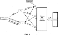
- FIG. 1 is a schematic diagram of a system for applying an active RFID tag according to the present invention, where a coordinator is connected to a control processor.
- FIG. 2 is a schematic diagram of a system for applying an active RFID tag according to the present invention, where a coordinator is separated from a control processor.
- the system for applying an active RFID tag includes: a coordinator, a reader/writer, a tag (i.e., an active RFID tag), and a control processor (i.e., a network and control computer).
- the reader/writer is connected to the control processor, and the coordinator is connected (shown in FIG. 1 ) to or separated (shown in FIG. 2 ) from the control processor.
- the active RFID tag, the reader/writer, and the coordinator have the received signal strength indication (RSSI) function, respectively including a low-cost and low-power consumption micro-power single-chip radio transceiver and microcontroller controlling the transceiver, or including a low-cost and low-power consumption micro-power single chip having the functions of the transceiver and the microcontroller.
- RSSI received signal strength indication
- the active RFID tag is capable of not only receiving the instruction signal from the coordinator, but also communicating with the reader/writer. In narrowband single frequency mode, the active RFID tag is easily subject to external interference. In addition, due to changes of the temperature, the working frequency of the crystal oscillator shifts out of aging, and in the actual application, the multipath effect and the Doppler effect may severely affect the reliability and stability of the system.
- the direct sequence spreading communication mode or another coding technology is used.
- the long-distance communication may be implemented, with an adjustable distance ranging between 0.1 to 2000 meters.
- the active RFID tag may use a battery for power supply, such as a Lithium battery, and is capable of switching between different channels, such as between a wakeup channel and a working channel.
- a battery for power supply such as a Lithium battery
- universally used 2.4 GHz free frequency band or other frequency bands be used.
- various interfaces may be provided for connecting to the sensor as required.
- the control processor is a computer, microcontroller, or another intelligent device capable of implementing the control function and processing and storing the data.
- the reader/writer may also implement the function of the coordinator so that the system does not require an independent coordinator.
- the reader/writer may work in the working mode of uninterruptedly and repeatedly transmitting the instruction signal on the wakeup channel for a period of time (the transmission time period needs to at least exceed the dormant period of the active RFID tag), and then switch to the working channel to communicate with the active RFID tag.
- the reader/writer may further implement the function of the control processor so that the system does not require an independent coordinator.
- the system may also be comprised of a reader/writer having the functions of the control processor, the coordinator, and the reader/writer simultaneously, and an active RFID tag; or comprised of a reader/writer having the functions of the coordinator and the reader/writer simultaneously, a control processor, and an active RFID tag.
- the control processor transmits an instruction or message to the coordinator in wired mode (shown in FIG. 1 ) or radio mode (shown in FIG. 2 ); and uninterruptedly and repeatedly transmits the instruction signal (shown in FIG. 3 ) to the active RFID tag on the wakeup channel (i.e., a first channel F1).
- FIG. 3 is a schematic diagram of working state of an active RFID tag according to the present invention
- FIG. 4 is a schematic diagram of comparing the time required for filtering invalid signals by the active RFID tag using hardware and the time required for filtering invalid signals by the active RFID tag using software according to the present invention.
- the active RFID tag stays in the standby state with low power consumption most of the time. It enters the working state for a short time period only after receiving a work instruction when and where it is required to work. After finishing a task, it quickly returns to the standby state. In the standby state, the active RFID tag periodically stays in the dormant state or interception state.
- the crystal oscillator and frequency synthesizer are all disabled, consuming less power.
- the crystal oscillator and the frequency synthesizer are started.
- standby state which is a basic state that the active RFID tag can maintain for a long time.
- the active RFID tag switches to the second channel and communicates with the reader/writer, or performs other operations according to commands, which is called the working state. This is a high power consumption state that the RFID tag can maintain for a short time period.
- the working duty cycle refers to the ratio of the time for the active RFID tag to intercept the received signals within each dormant period to the dormant time plus the total time for intercepting the received signals.
- the internal clock in the active RFID tag periodically starts the crystal oscillator and the frequency synthesizer to enable them to enter the signal interception state.
- the active RFID tag After the received signals are determined to be the invalid signals by the hard filter module, the active RFID tag immediately enters the dormant state and waits for a next chance for signal interception after wakeup. This avoids the case where a large quantity of time is required for filtering the invalid signals by only relying on soft filtering for the address code (shown in FIG. 4 ).
- the active RFID tag Only when the hard filtering fails to determine whether the received signals are invalid signals, the active RFID tag starts the soft filtering process, and continues to filter the signals until the signals are determined to be invalid signals and stops signal reception, or until the signals are determined valid signals and all received, and performs the actions according to the signal instruction. Or, if the instruction signal includes information requesting the multifunctional RFID tag to establish communication with the reader/writer, the active RFID tag switches to a working channel (i.e., a second channel F2) different from the wakeup channel to communicate with the reader/writer, execute the task issued by the control processor through the reader/writer, and transmits the obtained data to the reader/writer.
- a working channel i.e., a second channel F2
- the reader/writer transmits the data obtained from the active RFID tag to the control processor, and the application program of the control processor processes the data.
- control processes transmits an instruction signal by using the coordinator to only instruct the active RFID tag to transmit the data information
- the control processor after receiving the data from the active RFID tag by using the reader/writer, may transmit response information and instruct the coordinator to stop transmitting the instruction signal.
- the active RFID tag after receiving the response information, switches to the dormant state in the low-power consumption standby state, and waits for a next chance for interception after wakeup.
- Parameters of the active RFID tag such as the working frequency, transmit power, receiver sensitivity, and standby-work period, may be modified by the coordinator or the reader/writer in radio mode, or modified by the control signal transmitted by the microcontroller of the active RFID tag in wired mode.
- the following further describes the hardware filtering and software identification, and assesses power consumption in the hardware filtering method and the software identification method.
- the exclusion of the invalid signals from the received signals using the hard filter module may be implemented by using a demodulation mode filter submodule or a decoding module filter module.
- the filtering of the invalid signals by the demodulation mode filter module is specifically as follows: the active RFID tag reads an RSSI value of the demodulated signal, stops signal reception when the RSSI value is not larger than ambient noise, switches to the low-power consumption state; otherwise, continues to receive the signal after the demodulation to further determine by software identification the signal after the demodulation to be the instruction signals.
- the filtering of the invalid signals by the decoding mode filter module is specifically as follows: the active RFID tag using frequency spreading or other coding technologies directly uses its own communication code to decode the signals, stops signal reception if the desired signal complying the communication code fails to be obtained, switches to the dormant state in the low-power consumption standby state, and waits for a next chance for signal interception after wakeup; otherwise, starts the software identification to further determine whether the signal is the instruction signal.
- the simple hardware filtering method implements two-level filtering requiring the same frequency and modulation mode, but the optimal hardware filtering method needs to implement the three-level filtering requiring the same frequency, modulation mode, and coding mode. Therefore, the optimal hardware filtering method is capable of filtering out more invalid signals.
- the simple hardware filtering method is advantageous in that it is simple, less power-consuming than the pure software identification method, and widely supported by the hardware; and is disadvantageous in that when the RSSI value is determined by using the hardware, the RSSI value may fluctuate greatly, and generally the RSSI value needs to be read multiple times to calculate an average value, for example, an average value ranging about 100 ⁇ s.
- the signals not complying with the modulation mode are filtered out, and therefore the number of invalid signals failing to be filtered out is large and more time is spent in receiving the invalid signal.
- the optimal hardware filtering method is advantageous in that: the required time is short (only about 10 ⁇ s), and a longer distance of signal transmission is achieved because of the frequency spreading and coding gain; this identification mode implements finer filtering for the signals, and therefore except the valid signal, there are fewer invalid signals to be identified by the active RFID tag by using the software, and thus is less power-consuming.
- the optimal hardware filtering method is disadvantageous in that some of the current spreading transceiver chips do not provide the identification result externally.
- Software identification refers to identifying the address code of the received signals by using the soft filter module.
- the received signals, before identification have experienced two-level or even three-level filtering in frequency or modulation mode, or in additionally coding mode.
- a complete data signal packet needs to be received.
- the time for receiving the signal is at least twice that for receiving a complete instruction signal. Assume that a data packet is 16 bytes in length and the communication rate is 115.2 kbit/s, time more than 2 ms is generally required for receiving the packet.
- the signal reception may be immediately terminated.
- the subsequent portion of the signal is not received, and the active RFID tag switches to the lower-power consumption standby state.
- the address code of the signal is correct, that is, the signal is the instruction signal, the subsequent portion of the signal is received continually. Inc conclusion, the time spent in intercepting the invalid signals is averagely half that spent in interception the valid signals.
- the software identification method is advantageous in that: the implementation is simple, and the method is capable of directly identifying the instruction signal; in addition, if the signal is a signal having experienced spreading or coding and has the spreading gain or coding gain, the signal may be transmitted within a longer distance.
- the software identification method has its disadvantage: a large number of invalid signals need to be received, and the time for receiving and identifying the signal is long, thereby increasing the power consumption.
- Lithium battery having a capacity of 2300 mA is used, considering various factors, the available capacity is 2000 mA, and then the life cycle of an active RFID tag is 9.3 years. If the interception period is prolonged to 2 seconds, the life cycle of the battery may theoretically reach 12 years.
- the dormant period of the active RFID tag may be further shorted once, from 1 second to 0.5 second.
- the life cycle of the battery of an ultra long-distance active RFID tag (2000 meters) is calculated.
- the ultra long-distance active RFID tag is generally used for identifying ships and in the search and rescue work. Therefore, the average working time of such active RFID tag is far less than a short-distance active RFID tag (shorter than 100 meters).
- the active RFID tag works 4 times a day averagely, the communication volume produced in each time is 1000 received bytes (the working current is 25 mA), 1000 transmitted bytes (the working current is 200 mA), and each reception and transmission respectively takes 12 ms, then the average working current is 1.3 ⁇ A.
- the average working current is small as compared with other currents.
- the average working current is not a major factor determining the life cycle of the battery of an active RFID tag. Obviously, the life cycle of the battery of an ultra long-distance active RFID tag sees no difference from that of the battery of a short-distance active RFID tag.
- the ultra long-distance active RFID tag has another typical application scenario: volume transmission and temperature collection of the sensor: the current during signal transmission is 200 mA; assume that the ultra long-distance active RFID tag reports the temperature every 30 seconds, 16 bytes of data is transmitted, and 2 ms is took in each report, the response and instruction are intercepted once for 1 ms after each 5 reports, the interception current is 30 mA, and the dormant current of the active RFID tag 5 ⁇ A. The average working current is 18 ⁇ A, and therefore the life cycle of a No. 5 Lithium battery may reach 10 years.
- the software filtering method is adopted, to conclude a modest calculation, after the frequency synthesizer and the crystal oscillator work stably, if the average time for each interception is 2 ms (including the invalid signal-3 ms, and invalid signal-1.5 ms), and the electric power consumed for signal interception is 25 mA, then the average standby current is 51 ⁇ A; further assume that the active RFID tag works 10 times a day, each time produces a data volume of 2000 bytes and takes time of 250 ms, and the average working current is 24 mA, then the average electric power consumption is 7 ⁇ A, the dormant current is 5 ⁇ A, and the total electric power consumption is 63 ⁇ A.
- Lithium battery having a capacity of 2300 mA is used, considering various factors, the available capacity is 2000 mA, and then the life cycle of an active RFID tag is 3.6 years. If the dormant period is 2 seconds, the life cycle of the battery may reach 6 years. If the dormant period is adjusted to 8 seconds, the life cycle of the battery may theoretically reach over 10 years.
- the hardware filters out a large number of invalid signals, and the valid signal is identified using software identification.
- the working time of the active RFID tag is greatly reduced, that is, the working duty cycle is reduced so that the power consumption is greatly reduced.
- the hardware filtering method only fails to determine whether the received signals received by the active RFID tag are valid signals.
- the hardware filtering method is capable of excluding the majority of the invalid signals within a very short period of time (several microseconds), reducing the time spent by the active RFID tag in intercepting the invalid signals, and thereby greatly reducing the power consumption of the active RFID tag.
- the active RFID tag based on the hardware signal filtering, uses the software filtering method, thereby basically reducing the power consumption of the active RFID tag.
- the power consumption in the working state is not the major factor affecting the life cycle of the battery of the active RFID tag.
- the issue of prolonging the life cycle of the battery is transformed into reducing electricity leakage of the battery, which is relatively easy to resolve.
- the ordinary Li-Mn button cell having low cost and small size may be used to drive the active RFID tag. This greatly enlarges the application scope of the active RFID tag.
- the active RFID tag adopting the hardware filtering method is capable of implementing bidirectional communication and working on demand while lowering the power consumption.
- the technical solution is easy to implement, the cost is low, and the security is excellent, solving the problem of the existing RFID tag, such as electromagnetic pollution, signal congestion and mutual interference, lack of working flexibility and adaptability, and limited read-write distance.
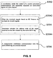
- FIG. 5 is a flowchart of a method for applying an active RFID tag according to the present invention.
- Step S502 A coordinator, under the control of a control processor, uninterruptedly and repeatedly transmits an instruction signal on a first channel.
- Step S504 An active RFID tag receives the instruction signal on the first channel during the time period of an interception state.
- Step S504 includes:
- Sub-step S5042 Filter the received signals based on the RF features to exclude the invalid signals. Specifically, with the simple hardware filtering method, an RSSI value of the demodulated signal is read, signal reception is immediately terminated when the RSSI value is not larger than ambient noise, and step S510 is performed; or with the optimal hardware filtering method, the active RFID tag using the spreading or other technologies directly uses its own communication code to decode the signal, signal reception is immediately terminated if the signal complying with the communication code fails to be obtained, and step S510 is performed.
- the active RFID tag may be powered by a Lithium battery, and use the direct sequence spreading or other coding communication technologies, and universally used 2.4 GHz free frequency band or other frequency bands.
- Sub-step S5044 Determine whether the address code of the signal received on the first channel by the active RFID tag. When it is determined that the address code is incorrect, signal reception is immediately terminated and step S510 is performed.
- Step S506 A reader/writer establishes communication with the active RFID tag on a second channel, and transmits the data obtained from the active RFID tag to the control processor.
- Step S508 If the control processor transmits the instruction signal by using the coordinator only to instruct the active RFID tag to transmit the data information, the control processor, the control processor, after receiving the data from the active RFID tag by using the reader/writer, transmits response information to the active RFID tag; after receiving the response information, the active RFID tag performs step S510.
- Step S510 Enter the low-consumption standby state.
- the active RFID tag may be applied to attendance management of buses, and an active RFID tag may be mounted on each bus. Each active RFID tag has a unique ID corresponding to the license plate number. The active RFID tag stays in the state of periodically intercepting signals on the wakeup channel.
- a coordinator connected to the infrared detector or an induction coil is deployed at each bus station. When the infrared sensor or the induction coil detects that a bus has stopped at the bus station, the coordinator is started to uninterruptedly transmit instruction information within 2 seconds at an interval of 5 to 10 seconds, instructing the active RFID tag to store the ID of the station and the current time. If during two consecutive minutes, the reader/writer installed at the station receives no signal, the coordinator stops transmitting the instruction signal until a new bus enters the station and the coordinator is restarted.
- the active RFID tag After receiving the instruction signal, the active RFID tag records, according to the instruction, the station ID and the time when the bus stops at the station.
- the active RFID tag does not store two same station IDs, but stores two time point under the same station ID, i.e., earliest time and latest time for calculating the total time during which the bus stays at the station.
- the coordinator deployed at the entrance at the destination station senses, using the infrared detector or the induction coil, that a bus has returned, and the coordinator is started to uninterruptedly transmit an instruction instructing the active RFID tag to transmit its recorded information to the reader/writer connected to a management computer by using the working channel of the reader/writer.
- the management computer After receiving the recorded information of the bus, the management computer transmits a response to the active RFID tag on the working channel. After receiving the response, the active RFID tag returns to the standby state of intercepting signals and does not receive any signal temporarily. Meanwhile, the computer also instructs the coordinator to stop working until another bus comes to the station.
- the management computer at the destination station is capable of collecting information required for management, such as running time, off-running time, specific running line of each bus, each station the bus stop each bus every day, and the duration of each stop every day. If a reader/writer connected to the general packet radio service (GPRS) module is further mounted on each bus, the entire system is also capable of implement real-time positioning of all the buses.
- GPRS general packet radio service
- FIG. 5 in combination with FIG. 7 and FIG. 8 .
- Step S602 A coordinator, independently or under the control of a control processor, uninterruptedly and repeatedly transmits a wakeup signal on a wakeup channel.
- Step S604 An active RFID tag receives the wakeup signal during the time period of an interception state.
- Step S606 A reader/writer establishes communication with the active RFID tag on a second channel.
- Step S608 The active RFID tag receives the action instruction index from the reader/writer, and searches out the action instruction corresponding to the action instruction index from a preset index-action mapping relationship and executes the action instruction.
- the wakeup signal includes information such as an address code, the sequence number of a task, and parameters of the task.
- the active RFID tag may identify the wakeup signal by using the address code, invoke (or query), by using the sequence number of the task, the program for executing a fixed mode operation corresponding to the sequence number and pre-stored in the active RFID tag, and assign a value to the program for executing a fixed mode operation corresponding to the sequence number by using the parameters.
- the program for executing a fixed mode operation refers the program of a specific task executed by the active RFID tag.
- One or multiple programs may be pre-stored in the active RFID tag, each corresponding to a sequence number. For example, three programs sequenced 1, 2, and 3 are pre-stored in the active RFID tag.
- the fixed mode operation executed by program 1 applicable to crossing-gate management is: transmitting the ID k times on the channel n using the transmit power P at the transmission interval of m seconds.
- the fixed mode operation executed by program 2 applicable to data collection of a sensor is: reading the data of the Lth sensor, and transmitting the data on the channel n using the transmit power P in S communication mode to the Rth receiver; the operation executed by program 3 is: transmitting the ID on the working channel, waiting for the response from the reader/writer for m microseconds, if no response, retransmitting the ID n times repeatedly until the response is received, establishing "dialog" communication with the reader/writer, and otherwise, returning to the low-power consumption standby state.
- the active RFID tag When the active RFID tag is required to execute a task, only the sequence number and related parameters of the task need to be transmitted to the active RFID tag, for example, in the wakeup signal, input 1 in the location of the action sequence number, input 1 for the transmit interval, input 3 for channel, input 2 for the power, and input 3 for the transmit times, i.e., "1-1-3-2-20".
- the system requires transmitting by the RFID tag the ID uninterruptedly 20 times on the channel 1 using the 3-level power at the interval of 1 second.
- the fixed mode operation may also execute a task lasting a long period of time and having low power consumption.
- a task lasting a long period of time and having low power consumption is applicable to a scenario where the transmission interval is long, and the requirement for the response time in response to a change of the working mode is not high, for example, a temperature monitoring system for city heating.
- the active RFID tag having a temperature sensor is preset, including setting the upper and lower limit values of the normal temperature, alarm action in the case of exceeding the limit value, interval for reporting the temperature in the case of normal temperature range and non-normal temperature. For example, when the temperature is normal, it is reported every 10 minutes; when the temperature is abnormal, it is reported every 10 seconds.
- These working parameters may be adjusted as required in radio mode. In such low-power consumption mode, the signal transmission interval is generally long and the signal duty cycle is very low. Therefore, even if the active RFID tag constantly transmits signals outward, problems such as the signal congestion generally produced by the active RFID tag will not occur.
- sequence numbers of the program for executing a fixed mode operation is set by using one byte (8 bits)
- theoretically sequence numbers may be set for 256 programs for executing the fixed mode operations.
- one or several programs for executing the fixed mode operations satisfying the specific project are written into the active RFID tag.
- the byte used for setting the sequence number of the program for executing a fixed mode operation is followed closely by a byte used for setting the parameters corresponding to the fixed mode operation.
- the types of the required parameters and the number of parameters are definite. When the sequence number if determined, the types of the parameters and the number of parameters are also determined.
- prescriptive action working mode Use of prescriptive action working mode is because in the prior art, the coordinator needs to clearly specifies the specific task to be executed by the active RFID tag in the wakeup signal, or needs to use an instruction of "instructing the active RFID tag to establish dialog communication with the reader/writer" so that after the control processor, after the active RFID tag establishes communication with the reader/writer, instructs the reader/writer to issue the specific task to be executed.
- These two modes both require a long period of communication process. Therefore, the time when the air channel is occupied is long, and the problems such as signal congestion and mutual interface tend to occur.
- a short wakeup signal including the task sequence number and the corresponding parameters need to be transmitted, thereby greatly reducing the time required for air communication and improving the communication efficiency. Meanwhile, multiple different tasks may be executed, and multiple functions may be implemented, thereby enhancing the flexibility in applications.
- the active RFID tag periodically stays in the dormant state or the interception state.
- the active RFID tag switches from the dormant state to the interception state, the active RFID tag starts the crystal oscillator and the frequency synthesizer to receive the wakeup signal.
- the active RFID tag invokes, by using the sequence number of the task, the program in fixed operation mode corresponding to the sequence number and pre-stored in the active RFID tag, assigns a value to the program in fixed operation mode corresponding to the sequence number by using the parameters, and then executes the program (the program generally includes an operation of transmitting the obtained data to the reader/writer after the active RFID tag executes the program and switches to the working channel) or executes the program for executing the fixed mode operation during communication with the reader/writer on the working channel (during the execution process of the program, the active RFID tag generally transmits the obtained data to the reader/writer).
- the reader/writer transmits the data obtained by the active RFID tag to the control processor for processing.
- the control processor after receiving the data from the active RFID tag by using the reader/writer, transmits response information to the active RFID tag. After receiving the response information, the active RFID tag enters the low-power consumption standby state, or transforms to another preset fixed mode operation, or delays the instruction transmitted by the control processor by using the reader/writer, and then executes the corresponding transform action according to the instruction.
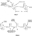
- the active RFID tag may receive the response using multiple methods. For example, the method may be intercepting (receiving) the response each time after transmitting the data, where the data transmission may be periodically initiated. As shown in FIG. 7 , each time after transmitting the ID, the active RFID tag intercepts whether there is response information coming from the reader/writer. Alternatively, the method may also be intercepting the response information once after transmitting the information multiple times. Such transmission is generally periodically initiated. As shown in FIG. 8 , after five times of data transmissions, the response is intercepted once. To reduce the time for waiting the response, the active RFID tag may also use the automatic response function of the majority of single-chip radio transceivers. In this way, after receiving the automatic response information, the active RFID tag may further delay in receiving an instruction transmitted by the control processor by using the reader/writer. If the instruction is received, the active RFID tag executes the corresponding transform action according to the instruction.
- the method may be intercepting (receiving) the response each time after transmitting the data, where the data transmission may be periodically initiated
- Parameters of the active RFID tag such as the working frequency, transmit power, receiver sensitivity, and standby-work period, may be modified by the coordinator or the reader/writer in radio mode, or modified by the control signal of the microcontroller of the active RFID tag.
Landscapes
- Engineering & Computer Science (AREA)
- Physics & Mathematics (AREA)
- Theoretical Computer Science (AREA)
- General Physics & Mathematics (AREA)
- Toxicology (AREA)
- Health & Medical Sciences (AREA)
- Microelectronics & Electronic Packaging (AREA)
- Computer Hardware Design (AREA)
- Computer Networks & Wireless Communication (AREA)
- Electromagnetism (AREA)
- General Health & Medical Sciences (AREA)
- Artificial Intelligence (AREA)
- Computer Vision & Pattern Recognition (AREA)
- Mobile Radio Communication Systems (AREA)
- Near-Field Transmission Systems (AREA)
Claims (10)
- Système pour communiquer avec une étiquette d'identification par radiofréquence RFID active, comprenant :un processeur de commande ;un coordinateur, configuré pour transmettre de façon ininterrompue et répétée un signal d'instruction pendant une période de temps préétablie sur un premier canal, où le signal d'instruction comprend une instruction de réveil et une instruction d'action ; etune étiquette RFID active, configurée pour recevoir un signal sur le premier canal, déterminer que le signal est le signal d'instruction, être réveillée en réponse à l'instruction de réveil au cours d'une période de temps d'un état d'interception et effectuer une opération en réponse à l'instruction d'action ;un lecteur/scripteur, connecté au processeur de commande et configuré pour établir une communication avec l'étiquette RFID active sur un second canal après que l'étiquette RFID active reçoit le signal d'instruction sur le premier canal ;dans lequel l'étiquette RFID active comprend :un premier module de filtre, configuré pour effectuer un premier filtrage pour le signal reçu par l'étiquette RFID active sur le premier canal pour exclure des signaux invalides ; etun second module de filtre, configuré pour effectuer un jugement de validité sur le signal reçu si le premier filtrage réussit pour déterminer si le signal reçu est le signal d'instruction pour l'étiquette RFID active sur la base d'informations numériques acheminées par le signal d'instruction.
- Système selon la revendication 1, dans lequel
le premier module de filtre est un module de filtre dur, et est configuré pour filtrer les signaux reçus sur la base de caractéristiques RF ; et
le second module de filtre est un module de filtre doux et configuré derrière le premier module de filtre, et est configuré pour filtrer l'exécution du jugement de validité sur la base des informations numériques acheminées par le signal, où les informations numériques représentent si un code d'adresse du signal reçu est correct. - Système selon la revendication 2, dans lequel le module de filtre dur comprend un sous-module de filtre de mode de modulation, dans lequel le sous-module de filtre de mode de modulation est configuré pour démoduler le signal reçu, lire une valeur d'indication d'intensité de signal reçu (RSSI) du signal démodulé, et refuser d'effectuer un traitement subséquent pour le signal reçu lorsque la valeur RSSI n'est pas supérieure au bruit ambiant ; et l'étiquette RFID active est en outre configurée pour commuter de l'état d'interception à un état dormant dans un mode veille.
- Système selon la revendication 2, dans lequel le module de filtre dur comprend un sous-module de filtre de décodage, dans lequel le sous-module de filtre de décodage est configuré pour décoder le signal reçu, lire le signal décodé, et refuser d'effectuer un traitement subséquent pour le signal reçu lorsque le signal décodé est un signal nul ou un signal de mutilation ; et l'étiquette RFID active est en outre configurée pour commuter de l'état d'interception à un état dormant dans un mode veille.
- Système selon l'une quelconque des revendications 1 à 4, comprenant en outre :un lecteur/scripteur, connecté au processeur de commande et configuré pour établir une communication avec l'étiquette RFID active sur un second canal après que l'étiquette RFID active reçoit le signal d'instruction sur le premier canal.
- Système selon la revendication 5, dans lequel le coordinateur et le lecteur/scripteur sont intégrés dans un module et seul un émetteur-récepteur est utilisé qui joue à la fois le rôle d'un coordinateur et d'un lecteur/scripteur.
- Procédé pour communiquer avec une étiquette d'identification par radiofréquence RFID active, comprenant les étapes suivantes :étape a (S502) : transmettre de façon ininterrompue et répétée, par un coordinateur, un signal d'instruction sur un premier canal pendant une période de temps préétablie, où le signal d'instruction comprend une instruction de réveil et une instruction d'action ;étape b (S504) : recevoir, par une étiquette RFID active, un signal sur le premier canal ; et déterminer, par l'étiquette RFID active, si le signal est le signal d'instruction ;réveiller l'étiquette RFID active en réponse à l'instruction de réveil au cours d'une période de temps d'un état d'interception ;effectuer, par l'étiquette RFID active, une opération en réponse à l'instruction d'action ;étape c (S506) : établir, par un lecteur/scripteur, une communication avec l'étiquette RFID active sur un second canal après que l'étiquette RFID active reçoit le signal d'instruction sur le premier canal ;dans lequel l'étape b (S504) comprend en outre une sous-étape d (S5042) : effectuer un premier filtrage pour le signal d'instruction reçu sur le premier canal pour exclure des signaux invalides ; etl'étape b (S504) comprend en outre une sous-étape e (S5044) : effectuer un jugement de validité sur des informations numériques acheminées par le signal d'instruction sur le signal reçu si le premier filtrage réussit pour déterminer si le signal reçu est le signal d'instruction pour l'étiquette RFID active sur la base d'informations numériques acheminées par le signal d'instruction.
- Procédé selon la revendication 7, dans lequel la sous-étape d (S5042) comprend en outre : la démodulation du signal reçu, la lecture d'une valeur d'indication d'intensité de signal reçu (RSSI) du signal démodulé, et le refus d'effectuer un traitement subséquent pour le signal reçu lorsque la valeur RSSI n'est pas supérieure au bruit ambiant ; et la commutation, par l'étiquette RFID active, de l'état d'interception à un état dormant dans un mode veille.
- Procédé selon la revendication 7, dans lequel la sous-étape d (S5042) comprend en outre le décodage du signal reçu, la lecture du signal décodé, et le refus d'effectuer un traitement subséquent pour le signal reçu lorsque le signal décodé est un signal nul ou un signal de mutilation ; et la commutation, par l'étiquette RFID active, de l'état d'interception à un état dormant dans un mode veille.
- Procédé selon l'une quelconque des revendications 7 à 9,
dans lequel la sous-étape S5042 comprend en outre : le filtrage des signaux reçus sur la base de caractéristiques RF ; et
dans lequel la sous-étape S5044 comprend en outre : le filtrage de l'exécution du jugement de validité sur la base des informations numériques acheminées par le signal, où les informations numériques représentent si un code d'adresse du signal reçu est correct.
Applications Claiming Priority (1)
| Application Number | Priority Date | Filing Date | Title |
|---|---|---|---|
| PCT/CN2009/075227 WO2011063572A1 (fr) | 2009-11-30 | 2009-11-30 | Étiquette électronique active, système d'application, et procédé s'y rapportant |
Publications (3)
| Publication Number | Publication Date |
|---|---|
| EP2509032A1 EP2509032A1 (fr) | 2012-10-10 |
| EP2509032A4 EP2509032A4 (fr) | 2014-02-26 |
| EP2509032B1 true EP2509032B1 (fr) | 2016-03-30 |
Family
ID=44065826
Family Applications (1)
| Application Number | Title | Priority Date | Filing Date |
|---|---|---|---|
| EP09851585.1A Active EP2509032B1 (fr) | 2009-11-30 | 2009-11-30 | Système d'application, et procédé s'y rapportant |
Country Status (3)
| Country | Link |
|---|---|
| US (2) | US9070061B2 (fr) |
| EP (1) | EP2509032B1 (fr) |
| WO (1) | WO2011063572A1 (fr) |
Cited By (1)
| Publication number | Priority date | Publication date | Assignee | Title |
|---|---|---|---|---|
| US11195072B1 (en) | 2018-02-28 | 2021-12-07 | United States Of America As Represented By The Administrator Of The National Aeronautics And Space Administration | Internal radio-frequency instrumentation system and method |
Families Citing this family (87)
| Publication number | Priority date | Publication date | Assignee | Title |
|---|---|---|---|---|
| US8570156B2 (en) * | 2010-09-01 | 2013-10-29 | Quake Global, Inc. | Pluggable small form-factor UHF RFID reader |
| US8947207B2 (en) | 2008-04-29 | 2015-02-03 | Quake Global, Inc. | Method and apparatus for a deployable radio-frequency identification portal system |
| US9071285B2 (en) | 2011-05-26 | 2015-06-30 | Cohere Technologies, Inc. | Modulation and equalization in an orthonormal time-frequency shifting communications system |
| US9130638B2 (en) | 2011-05-26 | 2015-09-08 | Cohere Technologies, Inc. | Modulation and equalization in an orthonormal time-frequency shifting communications system |
| US10667148B1 (en) | 2010-05-28 | 2020-05-26 | Cohere Technologies, Inc. | Methods of operating and implementing wireless communications systems |
| US9444514B2 (en) | 2010-05-28 | 2016-09-13 | Cohere Technologies, Inc. | OTFS methods of data channel characterization and uses thereof |
| US8976851B2 (en) | 2011-05-26 | 2015-03-10 | Cohere Technologies, Inc. | Modulation and equalization in an orthonormal time-frequency shifting communications system |
| US11943089B2 (en) | 2010-05-28 | 2024-03-26 | Cohere Technologies, Inc. | Modulation and equalization in an orthonormal time-shifting communications system |
| US10681568B1 (en) | 2010-05-28 | 2020-06-09 | Cohere Technologies, Inc. | Methods of data channel characterization and uses thereof |
| US9071286B2 (en) | 2011-05-26 | 2015-06-30 | Cohere Technologies, Inc. | Modulation and equalization in an orthonormal time-frequency shifting communications system |
| US9031141B2 (en) | 2011-05-26 | 2015-05-12 | Cohere Technologies, Inc. | Modulation and equalization in an orthonormal time-frequency shifting communications system |
| CN103136891B (zh) * | 2011-11-28 | 2015-07-29 | 鸿富锦精密工业(深圳)有限公司 | 防盗侦测电路及应用该防盗侦测电路的包装箱 |
| US9912507B2 (en) | 2012-06-25 | 2018-03-06 | Cohere Technologies, Inc. | Orthogonal time frequency space communication system compatible with OFDM |
| US10469215B2 (en) * | 2012-06-25 | 2019-11-05 | Cohere Technologies, Inc. | Orthogonal time frequency space modulation system for the Internet of Things |
| US10411843B2 (en) | 2012-06-25 | 2019-09-10 | Cohere Technologies, Inc. | Orthogonal time frequency space communication system compatible with OFDM |
| US10090972B2 (en) | 2012-06-25 | 2018-10-02 | Cohere Technologies, Inc. | System and method for two-dimensional equalization in an orthogonal time frequency space communication system |
| US9967758B2 (en) | 2012-06-25 | 2018-05-08 | Cohere Technologies, Inc. | Multiple access in an orthogonal time frequency space communication system |
| US9929783B2 (en) | 2012-06-25 | 2018-03-27 | Cohere Technologies, Inc. | Orthogonal time frequency space modulation system |
| US10003487B2 (en) | 2013-03-15 | 2018-06-19 | Cohere Technologies, Inc. | Symplectic orthogonal time frequency space modulation system |
| WO2014124318A1 (fr) * | 2013-02-08 | 2014-08-14 | Interdigital Patent Holdings, Inc. | Procédé et appareil pour incorporer une couche de protocole d'interface de service de l'internet des objets (iot) dans un nœud |
| US9841492B2 (en) | 2013-02-25 | 2017-12-12 | Quake Global, Inc. | Ceiling-mounted RFID-enabled tracking |
| JP6280571B2 (ja) | 2013-02-26 | 2018-02-14 | クエイク グローバル インコーポレイティッドQuake Global, Inc. | 自動識別リストバンドの方法及び装置 |
| US9901722B2 (en) | 2014-06-01 | 2018-02-27 | White Swell Medical Ltd | System and method for treatment of pulmonary edema |
| EP3940975A1 (fr) * | 2015-04-30 | 2022-01-19 | Cohere Technologies, Inc. | Système de modulation d'espace temps-fréquence orthogonal pour l'internet des objets |
| US10090973B2 (en) | 2015-05-11 | 2018-10-02 | Cohere Technologies, Inc. | Multiple access in an orthogonal time frequency space communication system |
| CN107925434B (zh) | 2015-05-11 | 2021-02-05 | 凝聚技术公司 | 用于数据的辛正交时频移位调制和传输的系统和方法 |
| US10149684B2 (en) | 2015-05-11 | 2018-12-11 | White Swell Medical Ltd | Systems and methods for reducing pressure at an outflow of a duct |
| US9866363B2 (en) | 2015-06-18 | 2018-01-09 | Cohere Technologies, Inc. | System and method for coordinated management of network access points |
| US10574317B2 (en) | 2015-06-18 | 2020-02-25 | Cohere Technologies, Inc. | System and method for providing wireless communication services using configurable broadband infrastructure shared among multiple network operators |
| CN114070701B (zh) | 2015-06-27 | 2024-05-14 | 凝聚技术股份有限公司 | 与ofdm兼容的正交时频空间通信系统 |
| US10892547B2 (en) | 2015-07-07 | 2021-01-12 | Cohere Technologies, Inc. | Inconspicuous multi-directional antenna system configured for multiple polarization modes |
| US10693581B2 (en) | 2015-07-12 | 2020-06-23 | Cohere Technologies, Inc. | Orthogonal time frequency space modulation over a plurality of narrow band subcarriers |
| WO2017044501A1 (fr) | 2015-09-07 | 2017-03-16 | Cohere Technologies | Accès multiple par modulation orthogonale d'espace temps-fréquence |
| US10118296B1 (en) * | 2015-09-10 | 2018-11-06 | X Development Llc | Tagged robot sensor data |
| US11038733B2 (en) | 2015-11-18 | 2021-06-15 | Cohere Technologies, Inc. | Orthogonal time frequency space modulation techniques |
| KR102655272B1 (ko) | 2015-12-09 | 2024-04-08 | 코히어 테크놀로지스, 아이엔씨. | 복소 직교 함수를 이용하는 파일럿 패킹 |
| EP3420641A4 (fr) | 2016-02-25 | 2019-12-11 | Cohere Technologies, Inc. | Conditionnement de signal de référence pour communications sans fil |
| US10693692B2 (en) | 2016-03-23 | 2020-06-23 | Cohere Technologies, Inc. | Receiver-side processing of orthogonal time frequency space modulated signals |
| US9667307B1 (en) | 2016-03-31 | 2017-05-30 | Cohere Technologies | Wireless telecommunications system for high-mobility applications |
| EP4262162A3 (fr) | 2016-03-31 | 2024-01-10 | Cohere Technologies, Inc. | Acquisition de canal utilisant un signal pilote orthogonal modulé dans l'espace temps-fréquence |
| CN109314682B (zh) | 2016-04-01 | 2021-09-21 | 凝聚技术公司 | 正交时频空间调制信号的迭代二维均衡 |
| US10063295B2 (en) | 2016-04-01 | 2018-08-28 | Cohere Technologies, Inc. | Tomlinson-Harashima precoding in an OTFS communication system |
| WO2017201467A1 (fr) | 2016-05-20 | 2017-11-23 | Cohere Technologies | Estimation et égalisation itératives de canaux avec des signaux de référence superposés |
| EP3497799A4 (fr) | 2016-08-12 | 2020-04-15 | Cohere Technologies, Inc. | Égalisation et décodage itératifs multiniveaux |
| US10826728B2 (en) | 2016-08-12 | 2020-11-03 | Cohere Technologies, Inc. | Localized equalization for channels with intercarrier interference |
| CN116865924A (zh) | 2016-08-12 | 2023-10-10 | 凝聚技术公司 | 正交时间频率空间信号的多用户复用 |
| US11310000B2 (en) | 2016-09-29 | 2022-04-19 | Cohere Technologies, Inc. | Transport block segmentation for multi-level codes |
| WO2018064605A1 (fr) | 2016-09-30 | 2018-04-05 | Cohere Technologies | Attribution de ressources d'utilisateur de liaison montante pour une modulation d'espace temps fréquence orthogonale |
| WO2018083537A1 (fr) | 2016-11-01 | 2018-05-11 | White Swell Medical Ltd | Systèmes et procédés de traitement de surcharge de liquides |
| EP3549200B1 (fr) | 2016-12-05 | 2022-06-29 | Cohere Technologies, Inc. | Accès sans fil fixe au moyen d'une modulation orthogonale d'espace temps-fréquence |
| WO2018129554A1 (fr) | 2017-01-09 | 2018-07-12 | Cohere Technologies | Brouillage de pilote pour estimation de voie |
| WO2018140837A1 (fr) | 2017-01-27 | 2018-08-02 | Cohere Technologies | Antenne multibande à largeur de faisceau variable |
| CN108460947A (zh) * | 2017-02-17 | 2018-08-28 | 成都西谷曙光数字技术有限公司 | 一种基于物联网技术的资产自动监管系统和方法 |
| CN110582241B (zh) | 2017-03-02 | 2023-05-26 | 怀特斯维尔医疗有限公司 | 用于降低管道的流出处的压力的系统和方法 |
| US11406393B2 (en) | 2017-03-19 | 2022-08-09 | White Swell Medical Ltd | Methods and devices for reducing pressure |
| US10568143B2 (en) | 2017-03-28 | 2020-02-18 | Cohere Technologies, Inc. | Windowed sequence for random access method and apparatus |
| EP3610582A4 (fr) | 2017-04-11 | 2021-01-06 | Cohere Technologies, Inc. | Communication numérique à l'aide de signaux à modulation orthogonale dans le temps, la fréquence et l'espace dispersés |
| EP4109983A1 (fr) | 2017-04-21 | 2022-12-28 | Cohere Technologies, Inc. | Techniques de communication utilisant des propriétés quasi-statiques de canaux sans fil |
| WO2018200577A1 (fr) | 2017-04-24 | 2018-11-01 | Cohere Technologies | Communication numérique utilisant un multiplexage par répartition en treillis |
| EP3616265A4 (fr) | 2017-04-24 | 2021-01-13 | Cohere Technologies, Inc. | Conceptions et fonctionnement d'antenne multifaisceau |
| WO2019014332A1 (fr) | 2017-07-12 | 2019-01-17 | Cohere Technologies | Schémas de modulation de données basés sur la transformée zak |
| WO2019032605A1 (fr) | 2017-08-11 | 2019-02-14 | Cohere Technologies | Technique de traçage de rayon pour mesures de canal sans fil |
| WO2019036492A1 (fr) | 2017-08-14 | 2019-02-21 | Cohere Technologies | Attribution de ressources de transmission par division de blocs de ressources physiques |
| WO2019051093A1 (fr) | 2017-09-06 | 2019-03-14 | Cohere Technologies | Réduction de treillis en modulation temporelle, fréquentielle et spatiale orthogonale |
| US11283561B2 (en) | 2017-09-11 | 2022-03-22 | Cohere Technologies, Inc. | Wireless local area networks using orthogonal time frequency space modulation |
| WO2019055861A1 (fr) | 2017-09-15 | 2019-03-21 | Cohere Technologies, Inc. | Réalisation d'une synchronisation dans un récepteur de signal d'espace temps-fréquence orthogonal |
| US11532891B2 (en) | 2017-09-20 | 2022-12-20 | Cohere Technologies, Inc. | Low cost electromagnetic feed network |
| WO2019068053A1 (fr) | 2017-09-29 | 2019-04-04 | Cohere Technologies, Inc. | Correction d'erreurs sans circuit de retour à l'aide de codes de contrôle de parité à faible densité non binaire |
| WO2019089986A1 (fr) | 2017-11-01 | 2019-05-09 | Cohere Technologies, Inc. | Précodage dans des systèmes sans fil à l'aide d'un multiplexage d'espace temps-fréquence orthogonal |
| WO2019113046A1 (fr) | 2017-12-04 | 2019-06-13 | Cohere Technologies, Inc. | Mise en oeuvre d'une modulation temporelle, fréquentielle et spatiale orthogonale pour des communications sans fil |
| WO2019157230A1 (fr) | 2018-02-08 | 2019-08-15 | Cohere Technologies, Inc. | Aspects d'estimation de canal pour une modulation spatiale temps-fréquence orthogonale pour des communications sans fil |
| CN108541049B (zh) * | 2018-03-02 | 2020-12-01 | 北京聚利科技有限公司 | 唤醒复合通行卡的方法及复合通行卡 |
| WO2019173775A1 (fr) | 2018-03-08 | 2019-09-12 | Cohere Technologies, Inc. | Planification de transmissions mimo multi-utilisateur dans des systèmes de communication sans fil fixes |
| CN108710933A (zh) * | 2018-05-03 | 2018-10-26 | 浙江朗因智能科技有限公司 | 一种用于物流运输中电子标签的设计方法 |
| EP3807952A4 (fr) | 2018-06-13 | 2021-07-28 | Cohere Technologies, Inc. | Étalonnage réciproque pour estimation de canal basée sur des statistiques de second ordre |
| US11522600B1 (en) | 2018-08-01 | 2022-12-06 | Cohere Technologies, Inc. | Airborne RF-head system |
| US11055502B2 (en) * | 2018-08-10 | 2021-07-06 | Nec Corporation | Sequential detection based classifications of RFID tags in three-dimensional space |
| US10685326B1 (en) * | 2019-02-06 | 2020-06-16 | Christie Lites Enterprises USA, LLC | Systems and methods for wirelessly monitoring inventory |
| US11793996B2 (en) | 2019-02-26 | 2023-10-24 | White Swell Medical Ltd | Devices and methods for treating edema |
| US11717652B2 (en) | 2019-02-26 | 2023-08-08 | White Swell Medical Ltd | Devices and methods for treating edema |
| US11660426B2 (en) | 2019-02-26 | 2023-05-30 | White Swell Medical Ltd | Devices and methods for treating edema |
| US11931560B2 (en) | 2019-02-26 | 2024-03-19 | White Swell Medical Ltd | Devices and methods for treating edema |
| US11724095B2 (en) | 2019-02-26 | 2023-08-15 | White Swell Medical Ltd | Devices and methods for treating edema |
| CN113114393B (zh) * | 2021-03-26 | 2022-04-22 | 华南理工大学 | 针对基于索引调制的环境反向散射通信在多接入信道下的低复杂度检测方法、读写器和系统 |
| CN113253644B (zh) * | 2021-05-12 | 2022-09-16 | 江南造船(集团)有限责任公司 | 设备工作模式的切换方法、微控制装置及船舶定位系统 |
| CN114363832B (zh) * | 2021-12-16 | 2023-05-23 | 江苏华锐频科技有限公司 | 一种信息发送的方法、射频标签、射频系统及存储介质 |
| CN114444631A (zh) * | 2022-01-25 | 2022-05-06 | 广州龙建达电子股份有限公司 | 一种基于rfid及物联网技术的库房档案资产管理方法及系统 |
Citations (1)
| Publication number | Priority date | Publication date | Assignee | Title |
|---|---|---|---|---|
| US20030214389A1 (en) * | 2002-04-01 | 2003-11-20 | Matrics, Inc. | Method and system for optimizing an interrogation of a tag population |
Family Cites Families (14)
| Publication number | Priority date | Publication date | Assignee | Title |
|---|---|---|---|---|
| US5790946A (en) * | 1993-07-15 | 1998-08-04 | Rotzoll; Robert R. | Wake up device for a communications system |
| US7019617B2 (en) * | 2002-10-02 | 2006-03-28 | Battelle Memorial Institute | Radio frequency identification devices, backscatter communication device wake-up methods, communication device wake-up methods and a radio frequency identification device wake-up method |
| US7106173B2 (en) * | 2003-01-03 | 2006-09-12 | Battelle Memorial Institute | Tags, wireless communication systems, tag communication methods, and wireless communications methods |
| US7023342B2 (en) * | 2003-09-17 | 2006-04-04 | The United States Of America As Represented By The Secretary Of The Navy | Continuous wave (CW)—fixed multiple frequency triggered, radio frequency identification (RFID) tag and system and method employing same |
| US7602274B2 (en) * | 2004-04-23 | 2009-10-13 | Microchip Technology Incorporated | Dynamic configuration of a radio frequency transponder |
| WO2007039328A1 (fr) * | 2005-09-28 | 2007-04-12 | International Business Machines Corporation | Pense-bete electronique adaptatif a base de regles de localisation d'objets personnels |
| KR100733986B1 (ko) * | 2005-12-08 | 2007-06-29 | 한국전자통신연구원 | Ip주소 기반 rfid 서비스를 위한 rfid 태그 및그를 이용한 ip주소 기반 rfid 서비스 방법 |
| US7471204B2 (en) * | 2006-07-07 | 2008-12-30 | Broadcom Corporation | Receiver architecture for canceling blocking signals |
| CN101236611B (zh) * | 2007-02-02 | 2012-07-18 | 成都西谷曙光数字技术有限公司 | 智能电子标签系统 |
| US7982585B2 (en) * | 2007-02-28 | 2011-07-19 | Li-Cheng Richard Zai | Method and apparatus for active RFID network |
| CN101059832A (zh) * | 2007-03-23 | 2007-10-24 | 东莞市太平洋计算机科技有限公司 | 一种有源rfid数据读写系统 |
| US8519906B2 (en) * | 2007-11-15 | 2013-08-27 | Loc8Tor Ltd. | Locating system |
| KR100958239B1 (ko) * | 2008-03-10 | 2010-05-17 | 엘에스산전 주식회사 | Rfid 태그 |
| CN101582122A (zh) * | 2009-06-23 | 2009-11-18 | 上海邮政科学研究院 | 一种具有唤醒功能的有源rfid系统 |
-
2009
- 2009-11-30 WO PCT/CN2009/075227 patent/WO2011063572A1/fr active Application Filing
- 2009-11-30 EP EP09851585.1A patent/EP2509032B1/fr active Active
-
2012
- 2012-05-29 US US13/482,734 patent/US9070061B2/en active Active
-
2015
- 2015-05-01 US US14/702,427 patent/US9405942B2/en not_active Expired - Fee Related
Patent Citations (1)
| Publication number | Priority date | Publication date | Assignee | Title |
|---|---|---|---|---|
| US20030214389A1 (en) * | 2002-04-01 | 2003-11-20 | Matrics, Inc. | Method and system for optimizing an interrogation of a tag population |
Cited By (1)
| Publication number | Priority date | Publication date | Assignee | Title |
|---|---|---|---|---|
| US11195072B1 (en) | 2018-02-28 | 2021-12-07 | United States Of America As Represented By The Administrator Of The National Aeronautics And Space Administration | Internal radio-frequency instrumentation system and method |
Also Published As
| Publication number | Publication date |
|---|---|
| WO2011063572A1 (fr) | 2011-06-03 |
| US9070061B2 (en) | 2015-06-30 |
| US20120235795A1 (en) | 2012-09-20 |
| EP2509032A1 (fr) | 2012-10-10 |
| EP2509032A4 (fr) | 2014-02-26 |
| US20150235060A1 (en) | 2015-08-20 |
| US9405942B2 (en) | 2016-08-02 |
Similar Documents
| Publication | Publication Date | Title |
|---|---|---|
| EP2509032B1 (fr) | Système d'application, et procédé s'y rapportant | |
| US7912443B2 (en) | Wake up device for communications system and methods | |
| Ansari et al. | Radio-triggered wake-ups with addressing capabilities for extremely low power sensor network applications | |
| US7215976B2 (en) | RFID device, system and method of operation including a hybrid backscatter-based RFID tag protocol compatible with RFID, bluetooth and/or IEEE 802.11x infrastructure | |
| KR100677481B1 (ko) | Rfid 기능을 내장한 이동 단말기의 안테나 공유 장치및 방법 | |
| US8994508B2 (en) | Inclusive or exclusive RFID tag interrogation and query round | |
| CN101122945A (zh) | Rfid系统以及在节能模式下操作该系统的方法 | |
| CN102612122A (zh) | 一种低功耗无线传感器网络系统及其控制唤醒方法 | |
| CN107862231B (zh) | 一种防止电子标签误唤醒系统 | |
| US7587195B2 (en) | Wireless communications apparatus made operative in dependent upon a received signal strength | |
| CN107607909B (zh) | 一种基于lf和uwb的室内定位方法及标签节点 | |
| CN103106381A (zh) | 一种多阅读器防碰撞的方法及装置 | |
| CN111669807A (zh) | 车载系统的射频唤醒 | |
| CN102831452A (zh) | 一种有源rfid系统的低功耗运行方法 | |
| CN102081745B (zh) | 有源电子标签及其应用系统和方法 | |
| CN102081743B (zh) | 有源电子标签及其应用系统和方法 | |
| WO2012171297A1 (fr) | Procédé de réveil de correspondance de signal, appareil et étiquette | |
| CN101583203A (zh) | 一种手机遥控装置及其遥控方法 | |
| CN102523020A (zh) | 无电源供电的电磁唤醒方法及其实施装置 | |
| CN102799839B (zh) | 有源rfid系统同步唤醒通信的方法 | |
| CN115119289A (zh) | Uwb标签的工作方法、装置、uwb标签及存储介质 | |
| Huang et al. | The Design of the management system for parking lot based on 2.45 GHz active RFID | |
| Huang et al. | Container transportation system using 2.45 GHz active RFID technology | |
| WO2024077479A1 (fr) | Procédé et appareil de communication à consommation d'énergie nulle, et equipement terminal et dispositif de réseau | |
| CN102799904B (zh) | 减少rfid系统数据处理量的方法 |
Legal Events
| Date | Code | Title | Description |
|---|---|---|---|
| PUAI | Public reference made under article 153(3) epc to a published international application that has entered the european phase |
Free format text: ORIGINAL CODE: 0009012 |
|
| 17P | Request for examination filed |
Effective date: 20120627 |
|
| AK | Designated contracting states |
Kind code of ref document: A1 Designated state(s): AT BE BG CH CY CZ DE DK EE ES FI FR GB GR HR HU IE IS IT LI LT LU LV MC MK MT NL NO PL PT RO SE SI SK SM TR |
|
| DAX | Request for extension of the european patent (deleted) | ||
| A4 | Supplementary search report drawn up and despatched |
Effective date: 20140127 |
|
| RIC1 | Information provided on ipc code assigned before grant |
Ipc: G06K 19/07 20060101ALI20140121BHEP Ipc: G06K 19/067 20060101AFI20140121BHEP |
|
| 17Q | First examination report despatched |
Effective date: 20141013 |
|
| GRAP | Despatch of communication of intention to grant a patent |
Free format text: ORIGINAL CODE: EPIDOSNIGR1 |
|
| INTG | Intention to grant announced |
Effective date: 20151012 |
|
| GRAS | Grant fee paid |
Free format text: ORIGINAL CODE: EPIDOSNIGR3 |
|
| GRAA | (expected) grant |
Free format text: ORIGINAL CODE: 0009210 |
|
| AK | Designated contracting states |
Kind code of ref document: B1 Designated state(s): AT BE BG CH CY CZ DE DK EE ES FI FR GB GR HR HU IE IS IT LI LT LU LV MC MK MT NL NO PL PT RO SE SI SK SM TR |
|
| REG | Reference to a national code |
Ref country code: GB Ref legal event code: FG4D |
|
| REG | Reference to a national code |
Ref country code: CH Ref legal event code: EP |
|
| REG | Reference to a national code |
Ref country code: AT Ref legal event code: REF Ref document number: 786080 Country of ref document: AT Kind code of ref document: T Effective date: 20160415 |
|
| REG | Reference to a national code |
Ref country code: IE Ref legal event code: FG4D |
|
| REG | Reference to a national code |
Ref country code: DE Ref legal event code: R096 Ref document number: 602009037443 Country of ref document: DE |
|
| REG | Reference to a national code |
Ref country code: LT Ref legal event code: MG4D |
|
| PG25 | Lapsed in a contracting state [announced via postgrant information from national office to epo] |
Ref country code: HR Free format text: LAPSE BECAUSE OF FAILURE TO SUBMIT A TRANSLATION OF THE DESCRIPTION OR TO PAY THE FEE WITHIN THE PRESCRIBED TIME-LIMIT Effective date: 20160330 Ref country code: FI Free format text: LAPSE BECAUSE OF FAILURE TO SUBMIT A TRANSLATION OF THE DESCRIPTION OR TO PAY THE FEE WITHIN THE PRESCRIBED TIME-LIMIT Effective date: 20160330 Ref country code: NO Free format text: LAPSE BECAUSE OF FAILURE TO SUBMIT A TRANSLATION OF THE DESCRIPTION OR TO PAY THE FEE WITHIN THE PRESCRIBED TIME-LIMIT Effective date: 20160630 Ref country code: GR Free format text: LAPSE BECAUSE OF FAILURE TO SUBMIT A TRANSLATION OF THE DESCRIPTION OR TO PAY THE FEE WITHIN THE PRESCRIBED TIME-LIMIT Effective date: 20160701 |
|
| REG | Reference to a national code |
Ref country code: NL Ref legal event code: MP Effective date: 20160330 |
|
| REG | Reference to a national code |
Ref country code: AT Ref legal event code: MK05 Ref document number: 786080 Country of ref document: AT Kind code of ref document: T Effective date: 20160330 |
|
| PG25 | Lapsed in a contracting state [announced via postgrant information from national office to epo] |
Ref country code: SE Free format text: LAPSE BECAUSE OF FAILURE TO SUBMIT A TRANSLATION OF THE DESCRIPTION OR TO PAY THE FEE WITHIN THE PRESCRIBED TIME-LIMIT Effective date: 20160330 Ref country code: LT Free format text: LAPSE BECAUSE OF FAILURE TO SUBMIT A TRANSLATION OF THE DESCRIPTION OR TO PAY THE FEE WITHIN THE PRESCRIBED TIME-LIMIT Effective date: 20160330 Ref country code: LV Free format text: LAPSE BECAUSE OF FAILURE TO SUBMIT A TRANSLATION OF THE DESCRIPTION OR TO PAY THE FEE WITHIN THE PRESCRIBED TIME-LIMIT Effective date: 20160330 |
|
| PG25 | Lapsed in a contracting state [announced via postgrant information from national office to epo] |
Ref country code: NL Free format text: LAPSE BECAUSE OF FAILURE TO SUBMIT A TRANSLATION OF THE DESCRIPTION OR TO PAY THE FEE WITHIN THE PRESCRIBED TIME-LIMIT Effective date: 20160330 |
|
| PG25 | Lapsed in a contracting state [announced via postgrant information from national office to epo] |
Ref country code: EE Free format text: LAPSE BECAUSE OF FAILURE TO SUBMIT A TRANSLATION OF THE DESCRIPTION OR TO PAY THE FEE WITHIN THE PRESCRIBED TIME-LIMIT Effective date: 20160330 Ref country code: IS Free format text: LAPSE BECAUSE OF FAILURE TO SUBMIT A TRANSLATION OF THE DESCRIPTION OR TO PAY THE FEE WITHIN THE PRESCRIBED TIME-LIMIT Effective date: 20160730 Ref country code: PL Free format text: LAPSE BECAUSE OF FAILURE TO SUBMIT A TRANSLATION OF THE DESCRIPTION OR TO PAY THE FEE WITHIN THE PRESCRIBED TIME-LIMIT Effective date: 20160330 |
|
| PG25 | Lapsed in a contracting state [announced via postgrant information from national office to epo] |
Ref country code: ES Free format text: LAPSE BECAUSE OF FAILURE TO SUBMIT A TRANSLATION OF THE DESCRIPTION OR TO PAY THE FEE WITHIN THE PRESCRIBED TIME-LIMIT Effective date: 20160330 Ref country code: PT Free format text: LAPSE BECAUSE OF FAILURE TO SUBMIT A TRANSLATION OF THE DESCRIPTION OR TO PAY THE FEE WITHIN THE PRESCRIBED TIME-LIMIT Effective date: 20160801 Ref country code: CZ Free format text: LAPSE BECAUSE OF FAILURE TO SUBMIT A TRANSLATION OF THE DESCRIPTION OR TO PAY THE FEE WITHIN THE PRESCRIBED TIME-LIMIT Effective date: 20160330 Ref country code: AT Free format text: LAPSE BECAUSE OF FAILURE TO SUBMIT A TRANSLATION OF THE DESCRIPTION OR TO PAY THE FEE WITHIN THE PRESCRIBED TIME-LIMIT Effective date: 20160330 Ref country code: SM Free format text: LAPSE BECAUSE OF FAILURE TO SUBMIT A TRANSLATION OF THE DESCRIPTION OR TO PAY THE FEE WITHIN THE PRESCRIBED TIME-LIMIT Effective date: 20160330 Ref country code: SK Free format text: LAPSE BECAUSE OF FAILURE TO SUBMIT A TRANSLATION OF THE DESCRIPTION OR TO PAY THE FEE WITHIN THE PRESCRIBED TIME-LIMIT Effective date: 20160330 Ref country code: RO Free format text: LAPSE BECAUSE OF FAILURE TO SUBMIT A TRANSLATION OF THE DESCRIPTION OR TO PAY THE FEE WITHIN THE PRESCRIBED TIME-LIMIT Effective date: 20160330 |
|
| REG | Reference to a national code |
Ref country code: FR Ref legal event code: PLFP Year of fee payment: 8 |
|
| PG25 | Lapsed in a contracting state [announced via postgrant information from national office to epo] |
Ref country code: BE Free format text: LAPSE BECAUSE OF FAILURE TO SUBMIT A TRANSLATION OF THE DESCRIPTION OR TO PAY THE FEE WITHIN THE PRESCRIBED TIME-LIMIT Effective date: 20160330 Ref country code: IT Free format text: LAPSE BECAUSE OF FAILURE TO SUBMIT A TRANSLATION OF THE DESCRIPTION OR TO PAY THE FEE WITHIN THE PRESCRIBED TIME-LIMIT Effective date: 20160330 |
|
| REG | Reference to a national code |
Ref country code: DE Ref legal event code: R097 Ref document number: 602009037443 Country of ref document: DE |
|
| PG25 | Lapsed in a contracting state [announced via postgrant information from national office to epo] |
Ref country code: DK Free format text: LAPSE BECAUSE OF FAILURE TO SUBMIT A TRANSLATION OF THE DESCRIPTION OR TO PAY THE FEE WITHIN THE PRESCRIBED TIME-LIMIT Effective date: 20160330 |
|
| PLBE | No opposition filed within time limit |
Free format text: ORIGINAL CODE: 0009261 |
|
| STAA | Information on the status of an ep patent application or granted ep patent |
Free format text: STATUS: NO OPPOSITION FILED WITHIN TIME LIMIT |
|
| 26N | No opposition filed |
Effective date: 20170103 |
|
| PG25 | Lapsed in a contracting state [announced via postgrant information from national office to epo] |
Ref country code: SI Free format text: LAPSE BECAUSE OF FAILURE TO SUBMIT A TRANSLATION OF THE DESCRIPTION OR TO PAY THE FEE WITHIN THE PRESCRIBED TIME-LIMIT Effective date: 20160330 |
|
| REG | Reference to a national code |
Ref country code: CH Ref legal event code: PL |
|
| PG25 | Lapsed in a contracting state [announced via postgrant information from national office to epo] |
Ref country code: CH Free format text: LAPSE BECAUSE OF NON-PAYMENT OF DUE FEES Effective date: 20161130 Ref country code: LI Free format text: LAPSE BECAUSE OF NON-PAYMENT OF DUE FEES Effective date: 20161130 |
|
| REG | Reference to a national code |
Ref country code: IE Ref legal event code: MM4A |
|
| PG25 | Lapsed in a contracting state [announced via postgrant information from national office to epo] |
Ref country code: LU Free format text: LAPSE BECAUSE OF NON-PAYMENT OF DUE FEES Effective date: 20161130 |
|
| REG | Reference to a national code |
Ref country code: DE Ref legal event code: R082 Ref document number: 602009037443 Country of ref document: DE |
|
| REG | Reference to a national code |
Ref country code: FR Ref legal event code: PLFP Year of fee payment: 9 |
|
| PG25 | Lapsed in a contracting state [announced via postgrant information from national office to epo] |
Ref country code: IE Free format text: LAPSE BECAUSE OF NON-PAYMENT OF DUE FEES Effective date: 20161130 |
|
| PG25 | Lapsed in a contracting state [announced via postgrant information from national office to epo] |
Ref country code: HU Free format text: LAPSE BECAUSE OF FAILURE TO SUBMIT A TRANSLATION OF THE DESCRIPTION OR TO PAY THE FEE WITHIN THE PRESCRIBED TIME-LIMIT; INVALID AB INITIO Effective date: 20091130 Ref country code: CY Free format text: LAPSE BECAUSE OF FAILURE TO SUBMIT A TRANSLATION OF THE DESCRIPTION OR TO PAY THE FEE WITHIN THE PRESCRIBED TIME-LIMIT Effective date: 20160330 |
|
| PG25 | Lapsed in a contracting state [announced via postgrant information from national office to epo] |
Ref country code: TR Free format text: LAPSE BECAUSE OF FAILURE TO SUBMIT A TRANSLATION OF THE DESCRIPTION OR TO PAY THE FEE WITHIN THE PRESCRIBED TIME-LIMIT Effective date: 20160330 Ref country code: MK Free format text: LAPSE BECAUSE OF FAILURE TO SUBMIT A TRANSLATION OF THE DESCRIPTION OR TO PAY THE FEE WITHIN THE PRESCRIBED TIME-LIMIT Effective date: 20160330 Ref country code: MC Free format text: LAPSE BECAUSE OF FAILURE TO SUBMIT A TRANSLATION OF THE DESCRIPTION OR TO PAY THE FEE WITHIN THE PRESCRIBED TIME-LIMIT Effective date: 20160330 |
|
| PG25 | Lapsed in a contracting state [announced via postgrant information from national office to epo] |
Ref country code: BG Free format text: LAPSE BECAUSE OF FAILURE TO SUBMIT A TRANSLATION OF THE DESCRIPTION OR TO PAY THE FEE WITHIN THE PRESCRIBED TIME-LIMIT Effective date: 20160330 |
|
| PG25 | Lapsed in a contracting state [announced via postgrant information from national office to epo] |
Ref country code: MT Free format text: LAPSE BECAUSE OF NON-PAYMENT OF DUE FEES Effective date: 20161130 |
|
| PGFP | Annual fee paid to national office [announced via postgrant information from national office to epo] |
Ref country code: GB Payment date: 20231220 Year of fee payment: 15 |
|
| PGFP | Annual fee paid to national office [announced via postgrant information from national office to epo] |
Ref country code: FR Payment date: 20231130 Year of fee payment: 15 Ref country code: DE Payment date: 20231208 Year of fee payment: 15 |