EP2508803A2 - A cooled double walled article - Google Patents
A cooled double walled article Download PDFInfo
- Publication number
- EP2508803A2 EP2508803A2 EP12159628A EP12159628A EP2508803A2 EP 2508803 A2 EP2508803 A2 EP 2508803A2 EP 12159628 A EP12159628 A EP 12159628A EP 12159628 A EP12159628 A EP 12159628A EP 2508803 A2 EP2508803 A2 EP 2508803A2
- Authority
- EP
- European Patent Office
- Prior art keywords
- wall
- apertures
- pitch
- diameter
- effusion
- Prior art date
- Legal status (The legal status is an assumption and is not a legal conclusion. Google has not performed a legal analysis and makes no representation as to the accuracy of the status listed.)
- Granted
Links
Images


Classifications
-
- F—MECHANICAL ENGINEERING; LIGHTING; HEATING; WEAPONS; BLASTING
- F23—COMBUSTION APPARATUS; COMBUSTION PROCESSES
- F23R—GENERATING COMBUSTION PRODUCTS OF HIGH PRESSURE OR HIGH VELOCITY, e.g. GAS-TURBINE COMBUSTION CHAMBERS
- F23R3/00—Continuous combustion chambers using liquid or gaseous fuel
- F23R3/02—Continuous combustion chambers using liquid or gaseous fuel characterised by the air-flow or gas-flow configuration
- F23R3/04—Air inlet arrangements
- F23R3/06—Arrangement of apertures along the flame tube
-
- F—MECHANICAL ENGINEERING; LIGHTING; HEATING; WEAPONS; BLASTING
- F23—COMBUSTION APPARATUS; COMBUSTION PROCESSES
- F23R—GENERATING COMBUSTION PRODUCTS OF HIGH PRESSURE OR HIGH VELOCITY, e.g. GAS-TURBINE COMBUSTION CHAMBERS
- F23R3/00—Continuous combustion chambers using liquid or gaseous fuel
- F23R3/002—Wall structures
-
- F—MECHANICAL ENGINEERING; LIGHTING; HEATING; WEAPONS; BLASTING
- F23—COMBUSTION APPARATUS; COMBUSTION PROCESSES
- F23R—GENERATING COMBUSTION PRODUCTS OF HIGH PRESSURE OR HIGH VELOCITY, e.g. GAS-TURBINE COMBUSTION CHAMBERS
- F23R2900/00—Special features of, or arrangements for continuous combustion chambers; Combustion processes therefor
- F23R2900/03041—Effusion cooled combustion chamber walls or domes
-
- F—MECHANICAL ENGINEERING; LIGHTING; HEATING; WEAPONS; BLASTING
- F23—COMBUSTION APPARATUS; COMBUSTION PROCESSES
- F23R—GENERATING COMBUSTION PRODUCTS OF HIGH PRESSURE OR HIGH VELOCITY, e.g. GAS-TURBINE COMBUSTION CHAMBERS
- F23R2900/00—Special features of, or arrangements for continuous combustion chambers; Combustion processes therefor
- F23R2900/03044—Impingement cooled combustion chamber walls or subassemblies
Definitions
- the present invention relates to a cooled double walled article and in particular relates to a gas turbine engine cooled double walled article.
- the present invention more particularly relates to a combustion chamber, a turbine blade, a turbine vane or a turbine shroud or other cooled double walled articles which comprise double walled structures.
- gas turbine engine combustion chambers comprise double walled structures comprising a first wall and a second wall arranged within and spaced from the first wall to form a cavity between the first wall and the second wall.
- the first wall has a plurality of impingement apertures extending there-through, whereby during operation a flow of coolant is arranged to flow through the impingement apertures and impinge upon an outer surface of the second wall.
- the second wall has a plurality of effusion apertures extending there-through, whereby in operation a flow of coolant is arranged to flow from the cavity through the effusion apertures and into the combustion chamber.
- Our European patent EP0576435B1 is an example.
- the impingement apertures in the first wall have the same diameter as the effusion apertures in the second wall, but there are twice as many effusion apertures in the second wall as there are impingement apertures in the first wall.
- the impingement of coolant on the outer surface of the second wall provides impingement cooling of the second wall.
- the coolant flows through the effusion apertures in the second wall to provide convective cooling of the second wall and the coolant flow out of the effusion apertures to form a film of coolant on the inner surface of the second wall to protect the inner surface of the second wall from combustion gases in the combustor.
- a problem with the use of this arrangement is that under some circumstances, for example due to manufacturing and/or location tolerances of the first wall and the second wall, it is possible for an impingement aperture in the first wall to be located directly in alignment with an effusion aperture in the second wall and this eventuality is undesirable. In some circumstances a plurality of impingement apertures in the first wall could be located such that each of the plurality of impingement apertures in the first wall was located directly in alignment with a respective one of the effusion apertures in the second wall.
- each of the impingement apertures in the first wall is located such that the coolant issuing from the impingement aperture impinges on the outer surface of the second wall and the coolant is then shared equally between the two effusion holes associated with that impingement aperture.
- an impingement aperture in the first wall is located in alignment with one of the effusion apertures in the second wall then the coolant issuing from the impingement aperture is preferentially supplied through that effusion aperture and the other effusion aperture associated with that impingement aperture is not supplied with coolant.
- the present invention seeks to provide a cooled double walled article comprising a first wall and a second wall spaced from the first wall which reduces the above-mentioned problem and has improved cooling.
- the present invention seeks to provide a combustion chamber comprising a first wall and a second wall arranged within and spaced from the first wall which reduces the above-mentioned problem and has improved cooling.
- a cooled double walled article comprising a first wall and a second wall, the second wall is spaced from the first wall to define a cavity between the first wall and the second wall, the first wall having a plurality of impingement apertures extending there-through, whereby during operation a flow of coolant is arranged to flow through the impingement apertures and impinge upon a first surface of the second wall, the second wall having a plurality of effusion apertures extending there-through, whereby in operation a flow of coolant is arranged to flow from the cavity through the effusion apertures and onto a second surface of the second wall, the impingement apertures have a first diameter, the effusion apertures have a second diameter, the impingement apertures have a first pitch, the effusion apertures have a second pitch, the first pitch is the distance between the centres of two adjacent impingement apertures, the second pitch is the distance between the centres of two adjacent effusion apertures, the impingement apertures have a first area, the eff
- the ratio of the first diameter to the second diameter may be at least 4, the ratio of the first pitch to the second pitch is at least 5 and the ratio of the first area to the second area is at least 16.
- the ratio of the first diameter to the second diameter may be 3, the ratio of the first pitch to the second pitch is 4.2 and the ratio of the first area to the second area is 9.
- the ratio of the first diameter to the second diameter may be 4, the ratio of the first pitch to the second pitch is 5.7 and the ratio of the first area to the second area is 16.
- the effusion apertures may have a minimum diameter of 0.5mm.
- the effusion apertures may have a diameter of 0.5mm, the second pitch is 2.8mm, the number of effusion apertures per square inch is 98, the impingement apertures have a diameter of 1.5mm, the first pitch is 11.7mm and the number of impingement apertures per square inch is 5.
- the effusion apertures may have a diameter of 0.5mm, the second pitch is 2.8mm, the number of effusion apertures per square inch is 98, the impingement apertures have a diameter of 2mm, the first pitch is 15.6mm and the number of impingement apertures per square inch is 3.
- the effusion apertures may have a diameter of 0.5mm, the second pitch is 3.9mm, the number of effusion apertures per square inch is 49, the impingement apertures have a diameter of 1.5mm, the first pitch is 16.5mm and the number of impingement apertures per square inch is 3.
- the effusion apertures may have a diameter of 0.5mm, the second pitch is 3.9mm, the number of effusion apertures per square inch is 49, the impingement apertures have a diameter of 2mm, the first pitch is 22.1 mm and the number of impingement apertures per square inch is 2.
- the effusion apertures may have a diameter of 0.5mm, the second pitch is 1.9mm, the number of effusion apertures per square inch is 196, the impingement apertures have a diameter of 1.5mm, the first pitch is 8.3mm and the number of impingement apertures per square inch is 11.
- the effusion apertures may have a diameter of 0.5mm, the second pitch is 1.9mm, the number of effusion apertures per square inch is 196, the impingement apertures have a diameter of 2mm, the first pitch is 11 mm and the number of impingement apertures per square inch is 6.
- the centres of the impingement apertures may be arranged at the corners of an equilateral triangle and the centres of the effusion apertures are arranged at the corners of an equilateral triangle.
- the effusion apertures may be arranged at an angle of at least 15°to the surface of the second wall.
- the effusion apertures may be arranged at an angle of 20°to the surface of the second wall.
- the effusion apertures may be arranged at an angle of 90°to the surface of the second wall.
- the cooled double walled article may be a combustion chamber, a turbine blade, a turbine vane or a turbine shroud.
- the combustion chamber may be a tubular combustion chamber and the first wall is an annular wall and the second wall is an annular wall.
- the combustion chamber may be a tubular combustion chamber and the first wall is an annular wall and the second wall comprises a plurality of tiles arranged circumferentially and axially to define an annular wall.
- the combustion chamber may be an annular combustion chamber and the first wall is an inner annular wall and the second wall is an annular wall arranged radially outwardly of the first wall or the first wall is an outer annular wall and the second wall is an annular wall arranged radially inwardly of the first wall.
- the combustion chamber may be an annular combustion chamber and the first wall is an inner annular wall and the second wall comprises a plurality of tiles arranged circumferentially and axially to define an annular wall arranged radially outwardly of the first wall or the first wall is an outer annular wall and the second wall comprises a plurality of tiles arranged circumferentially and axially to define an annular wall arranged radially inwardly of the first wall.
- the combustion chamber may be an annular combustion chamber and the first wall is an annular upstream end wall and the second wall comprises a plurality of heat shields arranged circumferentially to define an annular wall arranged downstream of the first wall.
- the plurality of impingement apertures and the plurality of effusion apertures may be arranged over at least a portion of the first wall and at least a portion of the second wall.
- the at least a portion of the first wall and the at least a portion of the second wall may be arranged at a position downstream of a mixing port extending through the first wall and second wall.
- the plurality of impingement apertures and the plurality of effusion apertures may be arranged over all of the first wall and over all of the second wall respectively.
- the plurality of effusion apertures may be arranged over all of at least one of the tiles.
- the plurality of effusion apertures may be arranged over all of each of the tiles.
- the impingement apertures may have a diameter equal to or greater than 1.5mm and equal to or less then 2mm.
- the first pitch may be equal to or greater than 8.3mm and equal to or less than 22.1 mm.
- the number of impingement apertures per square inch may be equal to or greater than 2 and equal to or less than 11.
- the number of impingement apertures per square cm may be equal to or greater than 0.2 and equal to or less than 1.7.
- the second pitch may be equal to or greater than 1.9mm and equal to or less than 3.9mm.
- the number of effusion apertures per square inch may be equal to or greater than 49 and equal to or less than 196.
- the number of effusion apertures per square cm may be equal to or greater than 8 and equal to or less than 30.
- the ratio of the number of effusion apertures per square inch to the number of impingement apertures per square inch may be equal to greater than 16 and equal to or less than 33.
- the ratio of the number of effusion apertures to the number of impingement apertures may be equal to greater than 18 and equal to or less than 32.
- the ratio of the second pitch to the second diameter may be equal to or greater than 3.8 and equal to or less than 7.8.
- the ratio of the first pitch to the first diameter may be equal to or greater than 5.5 and equal to or less than 11.
- the ratio of the first pitch to the first diameter may be greater than the ratio of the second pitch to the second diameter.
- the present invention also provides a combustion chamber comprising a first wall and a second wall, the second wall is arranged within and spaced from the first wall to define a cavity between the first wall and the second wall, the first wall having a plurality of impingement apertures extending there-through, whereby during operation a flow of coolant is arranged to flow through the impingement apertures and impinge upon an outer surface of the second wall, the second wall having a plurality of effusion apertures extending there-through, whereby in operation a flow of coolant is arranged to flow from the cavity through the effusion apertures and into the combustion chamber, the impingement apertures have a first diameter, the effusion apertures have a second diameter, the impingement apertures have a first pitch, the effusion apertures have a second pitch, the first pitch is the distance between the centres of two adjacent impingement apertures, the second pitch is the distance between the centres of two adjacent effusion apertures, the impingement apertures have a first area, the effusion apertures have a
- a turbofan gas turbine engine 10 as shown in figure 1 , comprises in axial flow series an intake 12, a fan 14, an intermediate pressure compressor 16, a high pressure compressor 18, a combustor 20, a high pressure turbine 22, an intermediate pressure turbine 24, a low pressure turbine 26 and an exhaust 28.
- the fan 14 is surrounded by a fan casing 30 and the fan casing 30 is secured to a core casing 34 via a plurality of fan outlet guide vanes 32.
- the combustion chamber 20 is shown more clearly in figure 2 and the combustion chamber 20 is an annular combustion chamber and comprises an upstream end wall 40, an inner annular wall 42 and an outer annular wall 44, the upstream ends 46 and 48 of the inner and outer annular walls 42 and 44 respectively are secured to the upstream end wall 40.
- the upstream end wall 40 has a plurality of apertures 50 in which are located fuel nozzles 52 in order to supply fuel and air into the annular combustion chamber 20.
- the upstream end wall 40, the inner annular wall 42 and the outer annular wall 44 are double wall arrangements.
- the double wall arrangement of the outer annular wall 44 is shown in figure 3 and the outer annular wall 44 comprises a first wall 54 and a second wall 56.
- the second wall 56 is arranged within and spaced from the first wall 54 to define a cavity 58 between the first wall 54 and the second wall 56.
- the first wall 54 has a plurality of impingement apertures 60 extending there-through, whereby during operation a flow of coolant, as shown by arrow A, is arranged to flow through the impingement apertures 60 into the cavity 58 and impinge upon an outer surface 62 of the second wall 56.
- the second wall 56 has a plurality of effusion apertures 64 extending there-through, whereby in operation a flow of coolant, as shown by arrow B, is arranged to flow from the cavity 58 through the effusion apertures 64 and into the combustion chamber to provide a film of coolant on the inner surface 66 of the second wall 56.
- the centres of the impingement apertures 60 are arranged at the corners of an equilateral triangle and the centres of the effusion apertures 64 are arranged at the corners of an equilateral triangle.
- the effusion apertures 64 may be arranged at an angle of between 15°to 90°to the surface of the second wall 56. Higher angles, e.g. closer to 90°, allow the number of effusion holes to be increased.
- the double wall arrangement of the outer annular wall 44 comprises a fully annular first wall 54 and the second wall 56 comprises a plurality of tiles 57 arranged circumferentially and axially to define an annular second wall 56, arranged radially inwardly of the annular first wall 54.
- first plurality of tiles 57A arranged circumferentially side by side, edge to edge, to form an annulus
- second plurality of tiles 57B arranged circumferentially side by side, edge to edge, to form an annulus
- a third plurality of tiles 57C arranged circumferentially side by side, edge to edge, to form an annulus.
- the second plurality of tiles 57B are arranged downstream of the first plurality of tiles 57A and the downstream ends of the first plurality of tiles 57A overlap but are spaced radially inwardly from the upstream ends of the second plurality of tiles 57B.
- the third plurality of tiles 57C are arranged downstream of the second plurality of tiles 57B and the downstream ends of the second plurality of tiles 57B overlap but are spaced radially inwardly from the upstream ends of the third plurality of tiles 57C.
- the double wall arrangement of the inner annular wall 42 may be arranged similarly, but the downstream ends of the upstream tiles 57A, 57B overlap but are spaced radially outwardly from the upstream ends of the downstream tiles 57B, 57C respectively.
- the double wall arrangement of the upstream end wall 40 may be arranged similarly, but there are a plurality of heat shields 59 in the second wall arranged downstream from the first wall.
- the impingement apertures 60 have a first diameter D 1
- the effusion apertures 64 have a second diameter D 2
- the impingement apertures 60 have a first pitch P 1
- the effusion apertures 64 have a second pitch P 2 , as shown in figure 4 .
- the first pitch P 1 is the distance between the centres of two adjacent impingement apertures 60.
- the second pitch P 2 is the distance between the centres of two adjacent effusion apertures 64.
- the impingement apertures 60 have a first area A 1
- the effusion apertures 64 have a second area A 2 , whereby the ratio of the first diameter D 1 to the second diameter D 2 is at least 3, the ratio of the first pitch P 1 to the second pitch P 2 is at least 4 and the ratio of the first area A 1 to the second area A 2 is at least 9.
- the ratio of the first diameter D 1 to the second diameter D 2 is at least 4, the ratio of the first pitch P 1 to the second pitch P 2 is at least 5 and the ratio of the first area A 1 to the second area A 2 is at least 16.
- the ratio of the first diameter D 1 to the second diameter D 2 may be 3, the ratio of the first pitch P 1 to the second pitch P 2 is 4.2 and the ratio of the first area A 1 to the second area A 2 is 9.
- the ratio of the first diameter D 1 to the second diameter D 2 may be 4, the ratio of the first pitch P 1 to the second pitch P 2 is 5.7 and the ratio of the first area A 1 to the second area A 2 is 16.
- the effusion apertures 64 have a minimum second diameter D 2 of 0.5mm in order to avoid blockage of the effusion apertures 64 during operation.
- the impingement apertures 60 may have a minimum first diameter D 1 of 1.5mm.
- the effusion apertures 60 have a second diameter D 2 of 0.5mm, the second pitch P 2 is 2.8mm, the number of effusion apertures 64 per square inch is 98 (the number of effusion apertures 64 per square cm is 15), the impingement apertures 60 have a first diameter D 1 of 1.5mm, the first pitch P 1 is 11.7mm and the number of impingement apertures 60 per square inch is 5 (the number of impingement apertures 60 per square cm is 0.8).
- the effusion apertures 64 have a second diameter D 2 of 0.5mm, the second pitch P 2 is 2.8mm, the number of effusion apertures 64 per square inch is 98 (the number of effusion apertures 64 per square cm is 15), the impingement apertures 60 have a first diameter D 1 of 2mm, the first pitch P 1 is 15.6mm and the number of impingement apertures 60 per square inch is 3 (the number of impingement apertures 60 per square cm is 0.5).
- the effusion apertures 64 have a second diameter D 2 of 0.5mm, the second pitch P 2 is 3.9mm, the number of effusion apertures 64 per square inch is 49 (the number of effusion apertures 64 per square cm is 8), the impingement apertures 60 have a first diameter D 1 of 1.5mm, the first pitch P 1 is 16.5mm and the number of impingement apertures 60 per square inch is 3 (the number of impingement apertures 60 per square cm is 0.4).
- the effusion apertures 64 have a second diameter D 2 of 0.5mm, the second pitch P 2 is 3.9mm, the number of effusion apertures 64 per square inch is 49 (the number of effusion apertures 64 per square cm is 8), the impingement apertures 60 have a first diameter D 1 of 2mm, the first pitch P 1 is 22.1 mm and the number of impingement apertures 60 per square inch is 2 (the number of impingement apertures 60 per square cm is 0.2).
- the effusion apertures 64 have a second diameter D 2 of 0.5mm, the second pitch P 2 is 1.9mm, the number of effusion apertures 64 per square inch is 196 (the number of effusion apertures 64 per square cm is 30), the impingement apertures 60 have a first diameter D 1 of 1.5mm, the first pitch P 1 is 8.3mm and the number of impingement apertures 60 per square inch is 11 (the number of impingement apertures 60 per square cm is 1.7).
- the effusion apertures 64 have a second diameter D 2 of 0.5mm, the second pitch P 2 is 1.9mm, the number of effusion apertures 64 per square inch is 196 (the number of effusion apertures 64 per square cm is 30), the impingement apertures 60 have a first diameter D 1 of 2mm, the first pitch P 1 is 11 mm and the number of impingement apertures 60 per square inch is 6 (the number of impingement apertures 60 per square cm is 0.9).
- the pressure drop across the first wall 54 of the double wall arrangement is 80% of the total pressure drop and the pressure drop across the second wall 56 of the double wall arrangement is 20% of the total pressure drop.
- each impingement aperture 60 in the first wall 54 supplies coolant, air, to a large number of effusion apertures 64 in the second wall 56, for example one impingement aperture 60 supplies coolant to eighteen or thirty two effusion apertures 64.
- this effusion aperture 64 aligned with the impingement aperture 60 takes only a small proportion of the coolant discharged by the impingement aperture 60 and the remaining coolant is shared, equally, between the remaining effusion apertures 64.
- impingement apertures 60 and effusion apertures 64 in an arrangement according to the present invention are that there is no need to maintain the first wall and second wall 54 and 56 in an accurate location.
- the impingement apertures 60 and effusion apertures 64 in an arrangement according to the present invention reduces the positional sensitivity of the impingement apertures 60 and effusion apertures 64 and in particular it allows large numbers of effusion apertures 64 to be used in the second wall 56 and this increases both the convective cooling and film cooling of the second wall 56.
- the impingement apertures 60 and effusion apertures 64 in an arrangement according to the present invention maintains a more uniform feed of coolant to the effusion apertures thereby increasing the cooling performance of the effusion apertures in the second wall 56.
- the present invention also allows minimum effusion aperture 64 diameters, minimum pitches between effusion apertures 64 and larger impingement aperture 60 diameters and this increases the surface area for convective cooling and film cooling effectiveness of the second wall resulting in enhanced cooling performance.
- Figure 5 shows an outer annular wall 44 which has one or more mixing ports 70 to define one or more mixing ducts 72 to supply mixing air into the annular combustion chamber 20.
- a plurality of impingement apertures 60 and a plurality of effusion apertures 64 are arranged over at least a portion of the first wall 54 and at least a portion of the second wall 56.
- the at least a portion of the first wall 54 and the at least a portion of the second wall 56 is arranged at a position downstream of the, or each, mixing port 70 extending through the first wall 54 and the second wall 56 of the outer annular wall 44.
- the same arrangement may be provided on an inner annular wall 42.
- the effusion apertures 64 positioned downstream of the mixing ports 70 are arranged at an angle of 90°to the inner surface of 66 of the second wall 56.
- this arrangement of impingement apertures 60 and effusion apertures 64 is significantly cooler than a previously used cooling arrangement using pedestal cooling downstream of the mixing ports 70.
- NOX Nirous oxide emissions
- the present invention may reduce NOX emissions if provided downstream of the mixing ports.
- a combustion chamber 120 shown in figure 6 is substantially the same as that shown in figure 2 and like parts are denoted by like numerals.
- the double wall arrangement of an outer annular wall 44B comprises a fully annular first wall 154 and the second wall 156 comprises a plurality of tiles 157 arranged circumferentially and axially to define an annular second wall 156, arranged radially inwardly of the annular first wall 154.
- a second plurality of tiles 157B arranged circumferentially side by side, edge to edge, to form an annulus.
- the second plurality of tiles 157B are arranged downstream of the first plurality of tiles 157A but the downstream ends of the first plurality of tiles 157A do not overlap the upstream ends of the second plurality of tiles 157B.
- the double wall arrangement of the inner annular wall 42B may be arranged similarly.
- the outer annular wall 44B and the inner annular wall 42B do not have stepped arrangement as do the outer annular wall 44 and the inner annular wall 42 in figure 2 .
- the double wall arrangement of the upstream end wall 40B may be arranged similarly, again there are a plurality of heat shields 159 in the second wall arranged downstream from the first wall.
- Figures 7 and 8 are similar to figures 3 and 4 but show an alternative arrangement of the effusion apertures 64 in the second wall 56 and in this arrangement the effusion apertures 64 are arranged at an angle of 90°to the inner surface of 66 of the second wall 56.
- Figure 9 shows a turbine aerofoil 220, either a turbine blade or a turbine vane.
- the turbine aerofoil 220 comprises a double wall arrangement including a first wall 254A and 254B and a second wall 256.
- the first wall 254A is arranged within and spaced from the second wall 254 to define a cavity 258A between the first wall 254A and the second wall 256.
- the first wall 254B is arranged within and spaced from the second wall 254 to define a cavity 258B between the first wall 254B and the second wall 256.
- the first walls 254A and 254B have a plurality of impingement apertures 260A and 260B respectively extending there-through, whereby during operation a flow of coolant, as shown by arrow A, is arranged to flow from chambers 266A and 266B within the second walls 254A and 254B respectively through the impingement apertures 260A and 260B into the cavities 258A and 258B respectively and impinge upon an outer surface 262A and 262B of the second wall 256.
- the second wall 256 has a plurality of effusion apertures 264A and 264 extending there-through, whereby in operation a flow of coolant, as shown by arrow B, is arranged to flow from the cavities 258A and 258B through the effusion apertures 264A and 264B respectively to provide a film of coolant on the outer surface 266 of the second wall 256 of the turbine aerofoil 220.
- the centres of the impingement apertures 260A and 260B are arranged at the corners of an equilateral triangle and the centres of the effusion apertures 264A and 264B are arranged at the corners of an equilateral triangle.
- the effusion apertures 264A and 264B may be arranged at an angle between 15° and 90° to the surface 266 of the second wall 256.
- the present invention has been described with reference to the outer annular wall of an annular combustion chamber in which the outer annular wall comprises a first wall, which is an annular wall, and a second wall, which is an annular wall, arranged radially inwardly of the first wall, the present invention is equally applicable to the inner annular wall of an annular combustion chamber in which the inner annular wall comprises a first wall, which is an annular wall, and a second wall, which is an annular wall, arranged radially outwardly of the first wall.
- the present invention is also applicable to an annular combustion chamber in which the inner annular wall comprises a first wall, which is an annular wall, and a second wall, which comprises a plurality of tiles arranged circumferentially and axially to define an annular wall, arranged radially outwardly of the first wall or the outer annular wall comprises a first wall, which is an annular wall, and a second wall, which comprises a plurality of tiles arranged circumferentially and axially to define an annular wall, arranged radially inwardly of the first wall.
- the present invention has been described with reference to an annular combustion chamber it is equally applicable to a tubular combustion chamber in which the first wall is an annular wall and the second wall is an annular wall radially within the first wall.
- the present invention is applicable to a tubular combustion chamber in which the first wall is an annular wall and the second wall comprises a plurality of tiles arranged circumferentially and axially to define an annular wall radially within the first wall.
- a turbine blade, a turbine vane and a turbine shroud has a first wall and a second wall, the second wall is spaced from the first wall to define a cavity between the first wall and the second wall, the first wall has a plurality of impingement apertures extending there-through, whereby during operation a flow of coolant is arranged to flow through the impingement apertures and impinge upon a first surface of the second wall, the second wall having a plurality of effusion apertures extending there-through, whereby in operation a flow of coolant is arranged to flow from the cavity through the effusion apertures and onto a second surface of the second wall.
Landscapes
- Engineering & Computer Science (AREA)
- Chemical & Material Sciences (AREA)
- Combustion & Propulsion (AREA)
- Mechanical Engineering (AREA)
- General Engineering & Computer Science (AREA)
- Turbine Rotor Nozzle Sealing (AREA)
Abstract
Description
- The present invention relates to a cooled double walled article and in particular relates to a gas turbine engine cooled double walled article. The present invention more particularly relates to a combustion chamber, a turbine blade, a turbine vane or a turbine shroud or other cooled double walled articles which comprise double walled structures.
- Currently gas turbine engine combustion chambers comprise double walled structures comprising a first wall and a second wall arranged within and spaced from the first wall to form a cavity between the first wall and the second wall. The first wall has a plurality of impingement apertures extending there-through, whereby during operation a flow of coolant is arranged to flow through the impingement apertures and impinge upon an outer surface of the second wall. The second wall has a plurality of effusion apertures extending there-through, whereby in operation a flow of coolant is arranged to flow from the cavity through the effusion apertures and into the combustion chamber. Our European patent
EP0576435B1 is an example. Typically the impingement apertures in the first wall have the same diameter as the effusion apertures in the second wall, but there are twice as many effusion apertures in the second wall as there are impingement apertures in the first wall. The impingement of coolant on the outer surface of the second wall provides impingement cooling of the second wall. The coolant flows through the effusion apertures in the second wall to provide convective cooling of the second wall and the coolant flow out of the effusion apertures to form a film of coolant on the inner surface of the second wall to protect the inner surface of the second wall from combustion gases in the combustor. - A problem with the use of this arrangement is that under some circumstances, for example due to manufacturing and/or location tolerances of the first wall and the second wall, it is possible for an impingement aperture in the first wall to be located directly in alignment with an effusion aperture in the second wall and this eventuality is undesirable. In some circumstances a plurality of impingement apertures in the first wall could be located such that each of the plurality of impingement apertures in the first wall was located directly in alignment with a respective one of the effusion apertures in the second wall. In a normal arrangement each of the impingement apertures in the first wall is located such that the coolant issuing from the impingement aperture impinges on the outer surface of the second wall and the coolant is then shared equally between the two effusion holes associated with that impingement aperture. However, if an impingement aperture in the first wall is located in alignment with one of the effusion apertures in the second wall then the coolant issuing from the impingement aperture is preferentially supplied through that effusion aperture and the other effusion aperture associated with that impingement aperture is not supplied with coolant. This leads to a reduction in the cooling performance of the second wall, due to a lack of, or reduced, convective cooling occurring in the other effusion aperture and a lack of, or reduced, film cooling of the inner surface of the second wall from the other effusion aperture.
- Accordingly the present invention seeks to provide a cooled double walled article comprising a first wall and a second wall spaced from the first wall which reduces the above-mentioned problem and has improved cooling.
- Accordingly the present invention seeks to provide a combustion chamber comprising a first wall and a second wall arranged within and spaced from the first wall which reduces the above-mentioned problem and has improved cooling.
- Accordingly the present invention a cooled double walled article comprising a first wall and a second wall, the second wall is spaced from the first wall to define a cavity between the first wall and the second wall, the first wall having a plurality of impingement apertures extending there-through, whereby during operation a flow of coolant is arranged to flow through the impingement apertures and impinge upon a first surface of the second wall, the second wall having a plurality of effusion apertures extending there-through, whereby in operation a flow of coolant is arranged to flow from the cavity through the effusion apertures and onto a second surface of the second wall, the impingement apertures have a first diameter, the effusion apertures have a second diameter, the impingement apertures have a first pitch, the effusion apertures have a second pitch, the first pitch is the distance between the centres of two adjacent impingement apertures, the second pitch is the distance between the centres of two adjacent effusion apertures, the impingement apertures have a first area, the effusion apertures have a second area, whereby the ratio of the first diameter to the second diameter is at least 3, the ratio of the first pitch to the second pitch is at least 4 and the ratio of the first area to the second area is at least 9.
- The ratio of the first diameter to the second diameter may be at least 4, the ratio of the first pitch to the second pitch is at least 5 and the ratio of the first area to the second area is at least 16.
- The ratio of the first diameter to the second diameter may be 3, the ratio of the first pitch to the second pitch is 4.2 and the ratio of the first area to the second area is 9.
- The ratio of the first diameter to the second diameter may be 4, the ratio of the first pitch to the second pitch is 5.7 and the ratio of the first area to the second area is 16.
- The effusion apertures may have a minimum diameter of 0.5mm.
- The effusion apertures may have a diameter of 0.5mm, the second pitch is 2.8mm, the number of effusion apertures per square inch is 98, the impingement apertures have a diameter of 1.5mm, the first pitch is 11.7mm and the number of impingement apertures per square inch is 5.
- The effusion apertures may have a diameter of 0.5mm, the second pitch is 2.8mm, the number of effusion apertures per square inch is 98, the impingement apertures have a diameter of 2mm, the first pitch is 15.6mm and the number of impingement apertures per square inch is 3.
- The effusion apertures may have a diameter of 0.5mm, the second pitch is 3.9mm, the number of effusion apertures per square inch is 49, the impingement apertures have a diameter of 1.5mm, the first pitch is 16.5mm and the number of impingement apertures per square inch is 3.
- The effusion apertures may have a diameter of 0.5mm, the second pitch is 3.9mm, the number of effusion apertures per square inch is 49, the impingement apertures have a diameter of 2mm, the first pitch is 22.1 mm and the number of impingement apertures per square inch is 2.
- The effusion apertures may have a diameter of 0.5mm, the second pitch is 1.9mm, the number of effusion apertures per square inch is 196, the impingement apertures have a diameter of 1.5mm, the first pitch is 8.3mm and the number of impingement apertures per square inch is 11.
- The effusion apertures may have a diameter of 0.5mm, the second pitch is 1.9mm, the number of effusion apertures per square inch is 196, the impingement apertures have a diameter of 2mm, the first pitch is 11 mm and the number of impingement apertures per square inch is 6.
- The centres of the impingement apertures may be arranged at the corners of an equilateral triangle and the centres of the effusion apertures are arranged at the corners of an equilateral triangle.
- The effusion apertures may be arranged at an angle of at least 15°to the surface of the second wall. The effusion apertures may be arranged at an angle of 20°to the surface of the second wall. The effusion apertures may be arranged at an angle of 90°to the surface of the second wall.
- The cooled double walled article may be a combustion chamber, a turbine blade, a turbine vane or a turbine shroud.
- The combustion chamber may be a tubular combustion chamber and the first wall is an annular wall and the second wall is an annular wall.
- The combustion chamber may be a tubular combustion chamber and the first wall is an annular wall and the second wall comprises a plurality of tiles arranged circumferentially and axially to define an annular wall.
- The combustion chamber may be an annular combustion chamber and the first wall is an inner annular wall and the second wall is an annular wall arranged radially outwardly of the first wall or the first wall is an outer annular wall and the second wall is an annular wall arranged radially inwardly of the first wall.
- The combustion chamber may be an annular combustion chamber and the first wall is an inner annular wall and the second wall comprises a plurality of tiles arranged circumferentially and axially to define an annular wall arranged radially outwardly of the first wall or the first wall is an outer annular wall and the second wall comprises a plurality of tiles arranged circumferentially and axially to define an annular wall arranged radially inwardly of the first wall.
- The combustion chamber may be an annular combustion chamber and the first wall is an annular upstream end wall and the second wall comprises a plurality of heat shields arranged circumferentially to define an annular wall arranged downstream of the first wall.
- The plurality of impingement apertures and the plurality of effusion apertures may be arranged over at least a portion of the first wall and at least a portion of the second wall.
- The at least a portion of the first wall and the at least a portion of the second wall may be arranged at a position downstream of a mixing port extending through the first wall and second wall.
- The plurality of impingement apertures and the plurality of effusion apertures may be arranged over all of the first wall and over all of the second wall respectively. The plurality of effusion apertures may be arranged over all of at least one of the tiles. The plurality of effusion apertures may be arranged over all of each of the tiles.
- The impingement apertures may have a diameter equal to or greater than 1.5mm and equal to or less then 2mm. The first pitch may be equal to or greater than 8.3mm and equal to or less than 22.1 mm. The number of impingement apertures per square inch may be equal to or greater than 2 and equal to or less than 11. The number of impingement apertures per square cm may be equal to or greater than 0.2 and equal to or less than 1.7. The second pitch may be equal to or greater than 1.9mm and equal to or less than 3.9mm. The number of effusion apertures per square inch may be equal to or greater than 49 and equal to or less than 196. The number of effusion apertures per square cm may be equal to or greater than 8 and equal to or less than 30. The ratio of the number of effusion apertures per square inch to the number of impingement apertures per square inch may be equal to greater than 16 and equal to or less than 33. The ratio of the number of effusion apertures to the number of impingement apertures may be equal to greater than 18 and equal to or less than 32. The ratio of the second pitch to the second diameter may be equal to or greater than 3.8 and equal to or less than 7.8. The ratio of the first pitch to the first diameter may be equal to or greater than 5.5 and equal to or less than 11. The ratio of the first pitch to the first diameter may be greater than the ratio of the second pitch to the second diameter.
- The present invention also provides a combustion chamber comprising a first wall and a second wall, the second wall is arranged within and spaced from the first wall to define a cavity between the first wall and the second wall, the first wall having a plurality of impingement apertures extending there-through, whereby during operation a flow of coolant is arranged to flow through the impingement apertures and impinge upon an outer surface of the second wall, the second wall having a plurality of effusion apertures extending there-through, whereby in operation a flow of coolant is arranged to flow from the cavity through the effusion apertures and into the combustion chamber, the impingement apertures have a first diameter, the effusion apertures have a second diameter, the impingement apertures have a first pitch, the effusion apertures have a second pitch, the first pitch is the distance between the centres of two adjacent impingement apertures, the second pitch is the distance between the centres of two adjacent effusion apertures, the impingement apertures have a first area, the effusion apertures have a second area, whereby the ratio of the first diameter to the second diameter is at least 3, the ratio of the first pitch to the second pitch is at least 4 and the ratio of the first area to the second area is at least 9.
- The present invention will be more fully described by way of example with reference to the accompanying drawings, in which:-
-
Figure 1 is a cut -away view of a turbofan gas turbine engine having a combustion chamber according to the present invention. -
Figure 2 is an enlarged cross-sectional view through a combustion chamber according to the present invention. -
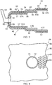
Figure 3 is a further enlarged cross-sectional view through the combustion chamber shown infigure 2 . -
Figure 4 is a partially cut-away view in the direction of arrow X infigure 3 showing a first and second wall of the combustion chamber. -
Figure 5 is a view in the direction of arrow Y infigure 3 . -
Figure 6 is an alternative enlarged cross-sectional view through a combustion chamber according to the present invention. -
Figure 7 is a further enlarged cross-sectional view through the combustion chamber shown infigure 2 . -
Figure 8 is a partially cut-away view in the direction of arrow Z infigure 7 showing a first and second wall of the combustion chamber. -
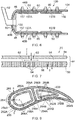
Figure 9 is a cross-sectional view through a turbine aerofoil according to the present invention. - A turbofan
gas turbine engine 10, as shown infigure 1 , comprises in axial flow series anintake 12, afan 14, anintermediate pressure compressor 16, ahigh pressure compressor 18, acombustor 20, ahigh pressure turbine 22, anintermediate pressure turbine 24, alow pressure turbine 26 and anexhaust 28. Thefan 14 is surrounded by afan casing 30 and thefan casing 30 is secured to acore casing 34 via a plurality of fan outlet guide vanes 32. - The
combustion chamber 20 is shown more clearly infigure 2 and thecombustion chamber 20 is an annular combustion chamber and comprises anupstream end wall 40, an innerannular wall 42 and an outerannular wall 44, the upstream ends 46 and 48 of the inner and outerannular walls upstream end wall 40. Theupstream end wall 40 has a plurality ofapertures 50 in which are locatedfuel nozzles 52 in order to supply fuel and air into theannular combustion chamber 20. Theupstream end wall 40, the innerannular wall 42 and the outerannular wall 44 are double wall arrangements. - The double wall arrangement of the outer
annular wall 44 is shown infigure 3 and the outerannular wall 44 comprises afirst wall 54 and asecond wall 56. Thesecond wall 56 is arranged within and spaced from thefirst wall 54 to define acavity 58 between thefirst wall 54 and thesecond wall 56. Thefirst wall 54 has a plurality ofimpingement apertures 60 extending there-through, whereby during operation a flow of coolant, as shown by arrow A, is arranged to flow through theimpingement apertures 60 into thecavity 58 and impinge upon anouter surface 62 of thesecond wall 56. Thesecond wall 56 has a plurality ofeffusion apertures 64 extending there-through, whereby in operation a flow of coolant, as shown by arrow B, is arranged to flow from thecavity 58 through theeffusion apertures 64 and into the combustion chamber to provide a film of coolant on theinner surface 66 of thesecond wall 56. The centres of theimpingement apertures 60 are arranged at the corners of an equilateral triangle and the centres of theeffusion apertures 64 are arranged at the corners of an equilateral triangle. The effusion apertures 64 may be arranged at an angle of between 15°to 90°to the surface of thesecond wall 56. Higher angles, e.g. closer to 90°, allow the number of effusion holes to be increased. - In this arrangement the double wall arrangement of the outer
annular wall 44 comprises a fully annularfirst wall 54 and thesecond wall 56 comprises a plurality oftiles 57 arranged circumferentially and axially to define an annularsecond wall 56, arranged radially inwardly of the annularfirst wall 54. Thus, there is a first plurality oftiles 57A arranged circumferentially side by side, edge to edge, to form an annulus, a second plurality oftiles 57B arranged circumferentially side by side, edge to edge, to form an annulus and a third plurality oftiles 57C arranged circumferentially side by side, edge to edge, to form an annulus. The second plurality oftiles 57B are arranged downstream of the first plurality oftiles 57A and the downstream ends of the first plurality oftiles 57A overlap but are spaced radially inwardly from the upstream ends of the second plurality oftiles 57B. The third plurality oftiles 57C are arranged downstream of the second plurality oftiles 57B and the downstream ends of the second plurality oftiles 57B overlap but are spaced radially inwardly from the upstream ends of the third plurality oftiles 57C. The double wall arrangement of the innerannular wall 42 may be arranged similarly, but the downstream ends of theupstream tiles downstream tiles upstream end wall 40 may be arranged similarly, but there are a plurality ofheat shields 59 in the second wall arranged downstream from the first wall. - The impingement apertures 60 have a first diameter D1, the
effusion apertures 64 have a second diameter D2, theimpingement apertures 60 have a first pitch P1 and theeffusion apertures 64 have a second pitch P2, as shown infigure 4 . The first pitch P1 is the distance between the centres of twoadjacent impingement apertures 60. The second pitch P2 is the distance between the centres of twoadjacent effusion apertures 64. The impingement apertures 60 have a first area A1, theeffusion apertures 64 have a second area A2, whereby the ratio of the first diameter D1 to the second diameter D2 is at least 3, the ratio of the first pitch P1 to the second pitch P2 is at least 4 and the ratio of the first area A1 to the second area A2 is at least 9. - The ratio of the first diameter D1 to the second diameter D2 is at least 4, the ratio of the first pitch P1 to the second pitch P2 is at least 5 and the ratio of the first area A1 to the second area A2 is at least 16.
- The ratio of the first diameter D1 to the second diameter D2 may be 3, the ratio of the first pitch P1 to the second pitch P2 is 4.2 and the ratio of the first area A1 to the second area A2 is 9.
- The ratio of the first diameter D1 to the second diameter D2 may be 4, the ratio of the first pitch P1 to the second pitch P2 is 5.7 and the ratio of the first area A1 to the second area A2 is 16.
- The effusion apertures 64 have a minimum second diameter D2 of 0.5mm in order to avoid blockage of the
effusion apertures 64 during operation. The impingement apertures 60 may have a minimum first diameter D1 of 1.5mm. - In one embodiment of the present invention in which the overall wall cooling porosity is 1%, where the overall wall cooling is effective flow area as a percentage of the wall area, the
effusion apertures 60 have a second diameter D2 of 0.5mm, the second pitch P2 is 2.8mm, the number ofeffusion apertures 64 per square inch is 98 (the number ofeffusion apertures 64 per square cm is 15), theimpingement apertures 60 have a first diameter D1 of 1.5mm, the first pitch P1 is 11.7mm and the number ofimpingement apertures 60 per square inch is 5 (the number ofimpingement apertures 60 per square cm is 0.8). - In a second embodiment of the present invention in which the overall wall cooling porosity is 1% the
effusion apertures 64 have a second diameter D2 of 0.5mm, the second pitch P2 is 2.8mm, the number ofeffusion apertures 64 per square inch is 98 (the number ofeffusion apertures 64 per square cm is 15), theimpingement apertures 60 have a first diameter D1 of 2mm, the first pitch P1 is 15.6mm and the number ofimpingement apertures 60 per square inch is 3 (the number ofimpingement apertures 60 per square cm is 0.5). - In a third embodiment of the present invention in which the overall wall cooling porosity is 0.5% the
effusion apertures 64 have a second diameter D2 of 0.5mm, the second pitch P2 is 3.9mm, the number ofeffusion apertures 64 per square inch is 49 (the number ofeffusion apertures 64 per square cm is 8), theimpingement apertures 60 have a first diameter D1 of 1.5mm, the first pitch P1 is 16.5mm and the number ofimpingement apertures 60 per square inch is 3 (the number ofimpingement apertures 60 per square cm is 0.4). - In a fourth embodiment of the present invention in which the overall wall cooling porosity is 0.05% the
effusion apertures 64 have a second diameter D2 of 0.5mm, the second pitch P2 is 3.9mm, the number ofeffusion apertures 64 per square inch is 49 (the number ofeffusion apertures 64 per square cm is 8), theimpingement apertures 60 have a first diameter D1 of 2mm, the first pitch P1 is 22.1 mm and the number ofimpingement apertures 60 per square inch is 2 (the number ofimpingement apertures 60 per square cm is 0.2). - In a fifth embodiment of the present invention in which the overall wall cooling porosity is 2%, the
effusion apertures 64 have a second diameter D2 of 0.5mm, the second pitch P2 is 1.9mm, the number ofeffusion apertures 64 per square inch is 196 (the number ofeffusion apertures 64 per square cm is 30), theimpingement apertures 60 have a first diameter D1 of 1.5mm, the first pitch P1 is 8.3mm and the number ofimpingement apertures 60 per square inch is 11 (the number ofimpingement apertures 60 per square cm is 1.7). - In a sixth embodiment of the present invention in which the overall wall cooling porosity is 2%, the
effusion apertures 64 have a second diameter D2 of 0.5mm, the second pitch P2 is 1.9mm, the number ofeffusion apertures 64 per square inch is 196 (the number ofeffusion apertures 64 per square cm is 30), theimpingement apertures 60 have a first diameter D1 of 2mm, the first pitch P1 is 11 mm and the number ofimpingement apertures 60 per square inch is 6 (the number ofimpingement apertures 60 per square cm is 0.9). - Other suitable arrangements may be used, in which the overall wall cooling porosity is between and including 0.05% to 3%.
- The pressure drop across the
first wall 54 of the double wall arrangement is 80% of the total pressure drop and the pressure drop across thesecond wall 56 of the double wall arrangement is 20% of the total pressure drop. - In the present invention each
impingement aperture 60 in thefirst wall 54 supplies coolant, air, to a large number ofeffusion apertures 64 in thesecond wall 56, for example oneimpingement aperture 60 supplies coolant to eighteen or thirty twoeffusion apertures 64. In operation of the present invention if one of theeffusion apertures 64 in thesecond wall 56 is aligned with one of theimpingement apertures 60 in thefirst wall 54, due to manufacturing tolerances and/or location tolerances, then thiseffusion aperture 64 aligned with theimpingement aperture 60 takes only a small proportion of the coolant discharged by theimpingement aperture 60 and the remaining coolant is shared, equally, between the remainingeffusion apertures 64. In the case of oneimpingement aperture 60 supplying coolant to eighteeneffusion apertures 64, only 11 % of the coolant supplied byimpingement aperture 60 flows through the alignedeffusion aperture 64 and the remaining 89% of the coolant is supplied to the remaining seventeeneffusion apertures 64 and this results in each of the remainingeffusion apertures 64 receiving 94% of the coolant it would have received if theeffusion aperture 64 was not aligned with theimpingement aperture 60. If this is compared with the previous arrangement discussed above in which an effusion aperture in the second wall is aligned with an impingement aperture in the first wall all of the coolant supplied by that impingement aperture would flow through the aligned effusion aperture and no coolant would be supplied to the other effusion apertures associated with that impingement aperture and this results in a reduction in the cooling performance of the second wall, due to a lack of, or reduced, convective cooling occurring in the other effusion apertures and a lack of, or reduced, film cooling of the inner surface of the second wall from the other effusion apertures. - The advantage of using
impingement apertures 60 andeffusion apertures 64 in an arrangement according to the present invention is that there is no need to maintain the first wall andsecond wall effusion apertures 64 in an arrangement according to the present invention reduces the positional sensitivity of theimpingement apertures 60 andeffusion apertures 64 and in particular it allows large numbers ofeffusion apertures 64 to be used in thesecond wall 56 and this increases both the convective cooling and film cooling of thesecond wall 56. The impingement apertures 60 andeffusion apertures 64 in an arrangement according to the present invention maintains a more uniform feed of coolant to the effusion apertures thereby increasing the cooling performance of the effusion apertures in thesecond wall 56. The present invention also allowsminimum effusion aperture 64 diameters, minimum pitches betweeneffusion apertures 64 andlarger impingement aperture 60 diameters and this increases the surface area for convective cooling and film cooling effectiveness of the second wall resulting in enhanced cooling performance. -
Figure 5 shows an outerannular wall 44 which has one ormore mixing ports 70 to define one ormore mixing ducts 72 to supply mixing air into theannular combustion chamber 20. A plurality ofimpingement apertures 60 and a plurality ofeffusion apertures 64 are arranged over at least a portion of thefirst wall 54 and at least a portion of thesecond wall 56. In this arrangement the at least a portion of thefirst wall 54 and the at least a portion of thesecond wall 56 is arranged at a position downstream of the, or each, mixingport 70 extending through thefirst wall 54 and thesecond wall 56 of the outerannular wall 44. The same arrangement may be provided on an innerannular wall 42. The effusion apertures 64 positioned downstream of the mixingports 70 are arranged at an angle of 90°to the inner surface of 66 of thesecond wall 56. In a test on this arrangement ofimpingement apertures 60 andeffusion apertures 64 is significantly cooler than a previously used cooling arrangement using pedestal cooling downstream of the mixingports 70. In this test it was observed that there was a reduction in NOX, (Nitrous oxide emissions), and it is believed that the coolant flow from theeffusion apertures 64 downstream of the mixingports 70 may have become entrained by and slightly quenched near wall hot recirculating combustion gases downstream of the mixingports 70. Thus, the present invention may reduce NOX emissions if provided downstream of the mixing ports. - A
combustion chamber 120 shown infigure 6 is substantially the same as that shown infigure 2 and like parts are denoted by like numerals. In thecombustion chamber 120 the double wall arrangement of an outerannular wall 44B comprises a fully annularfirst wall 154 and thesecond wall 156 comprises a plurality oftiles 157 arranged circumferentially and axially to define an annularsecond wall 156, arranged radially inwardly of the annularfirst wall 154. Thus, there is a first plurality oftiles 157A arranged circumferentially side by side, edge to edge, to form an annulus, and a second plurality oftiles 157B arranged circumferentially side by side, edge to edge, to form an annulus. The second plurality oftiles 157B are arranged downstream of the first plurality oftiles 157A but the downstream ends of the first plurality oftiles 157A do not overlap the upstream ends of the second plurality oftiles 157B. The double wall arrangement of the innerannular wall 42B may be arranged similarly. The outerannular wall 44B and the innerannular wall 42B do not have stepped arrangement as do the outerannular wall 44 and the innerannular wall 42 infigure 2 . The double wall arrangement of theupstream end wall 40B may be arranged similarly, again there are a plurality ofheat shields 159 in the second wall arranged downstream from the first wall. -
Figures 7 and8 are similar tofigures 3 and4 but show an alternative arrangement of theeffusion apertures 64 in thesecond wall 56 and in this arrangement theeffusion apertures 64 are arranged at an angle of 90°to the inner surface of 66 of thesecond wall 56. -
Figure 9 shows aturbine aerofoil 220, either a turbine blade or a turbine vane. Theturbine aerofoil 220 comprises a double wall arrangement including afirst wall second wall 256. Thefirst wall 254A is arranged within and spaced from the second wall 254 to define acavity 258A between thefirst wall 254A and thesecond wall 256. Similarly thefirst wall 254B is arranged within and spaced from the second wall 254 to define acavity 258B between thefirst wall 254B and thesecond wall 256. Thefirst walls impingement apertures chambers second walls impingement apertures cavities outer surface second wall 256. Thesecond wall 256 has a plurality ofeffusion apertures cavities effusion apertures outer surface 266 of thesecond wall 256 of theturbine aerofoil 220. The centres of theimpingement apertures effusion apertures effusion apertures surface 266 of thesecond wall 256. - Although the present invention has been described with reference to the outer annular wall of an annular combustion chamber in which the outer annular wall comprises a first wall, which is an annular wall, and a second wall, which is an annular wall, arranged radially inwardly of the first wall, the present invention is equally applicable to the inner annular wall of an annular combustion chamber in which the inner annular wall comprises a first wall, which is an annular wall, and a second wall, which is an annular wall, arranged radially outwardly of the first wall.
- The present invention is also applicable to an annular combustion chamber in which the inner annular wall comprises a first wall, which is an annular wall, and a second wall, which comprises a plurality of tiles arranged circumferentially and axially to define an annular wall, arranged radially outwardly of the first wall or the outer annular wall comprises a first wall, which is an annular wall, and a second wall, which comprises a plurality of tiles arranged circumferentially and axially to define an annular wall, arranged radially inwardly of the first wall.
- Although the present invention has been described with reference to an annular combustion chamber it is equally applicable to a tubular combustion chamber in which the first wall is an annular wall and the second wall is an annular wall radially within the first wall. In addition the present invention is applicable to a tubular combustion chamber in which the first wall is an annular wall and the second wall comprises a plurality of tiles arranged circumferentially and axially to define an annular wall radially within the first wall.
- Although the present invention has been described with reference to a combustion chamber with an annular first wall and an annular second wall radially inwardly or radially outwardly of the first wall it is equally applicable to a first wall and a second wall downstream of the first wall.
- Although the present invention has been described with reference to a combustion chamber it is equally applicable to a turbine blade, a turbine vane or a turbine shroud. A turbine blade, a turbine vane and a turbine shroud has a first wall and a second wall, the second wall is spaced from the first wall to define a cavity between the first wall and the second wall, the first wall has a plurality of impingement apertures extending there-through, whereby during operation a flow of coolant is arranged to flow through the impingement apertures and impinge upon a first surface of the second wall, the second wall having a plurality of effusion apertures extending there-through, whereby in operation a flow of coolant is arranged to flow from the cavity through the effusion apertures and onto a second surface of the second wall.
Claims (15)
- A cooled double walled article (20) comprising a first wall (54) and a second wall (56), the second wall (56) is spaced from the first wall (54) to define a cavity (58) between the first wall (54) and the second wall (56), the first wall (54) having a plurality of impingement apertures (60) extending there-through, whereby during operation a flow of coolant is arranged to flow through the impingement apertures (60) and impinge upon a first surface ( ) of the second wall (56), the second wall (56) having a plurality of effusion apertures (64) extending there-through, whereby in operation a flow of coolant is arranged to flow from the cavity (58) through the effusion apertures (64) and onto a second surface () of the second wall (56), the impingement apertures (60) have a first diameter (D1), the effusion apertures (64) have a second diameter (D2), the impingement apertures (60) have a first pitch (P1), the effusion apertures (64) have a second pitch (P2), the first pitch (P1) is the distance between the centres of two adjacent impingement apertures (60), the second pitch (P2) is the distance between the centres of two adjacent effusion apertures (64), the impingement apertures (60) have a first area (A1), the effusion apertures (64) have a second area (A2), characterised in that the ratio of the first diameter (D1) to the second diameter (D2) is at least 3, the ratio of the first pitch (P1) to the second pitch (P2) is at least 4 and the ratio of the first area (A1) to the second area (A2) is at least 9.
- An article as claimed in claim 1 wherein the ratio of the first diameter (D1) to the second diameter (D2) is at least 4, the ratio of the first pitch (P1) to the second pitch (P2) is at least 5 and the ratio of the first area (A1) to the second area (A2) is at least 16.
- An article as claimed in claim 1 wherein the ratio of the first diameter (D1) to the second diameter (D2) is 3, the ratio of the first pitch (P1) to the second pitch (P2) is 4.2 and the ratio of the first area (A1) to the second area (A2) is 9.
- An article as claimed in claim 1 wherein the ratio of the first diameter (D1) to the second diameter (D2) is 4, the ratio of the first pitch (P1) to the second pitch (P2) is 5.7 and the ratio of the first area (A1) to the second area (A2) is 16.
- An article as claimed in any of claims 1 to 4 wherein the effusion apertures (64) have a minimum diameter of 0.5mm.
- An article as claimed in any of claims 1 to 5 wherein the effusion apertures (64) have a diameter of 0.5mm, the second pitch is 2.8mm, the number of effusion apertures (64) per square centimetre is 15, the impingement apertures (60) have a diameter of 1.5mm, the first pitch is 11.7mm and the number of impingement apertures per square centimetre is 0.8 or the effusion apertures (64) have a diameter of 0.5mm, the second pitch is 2.8mm, the number of effusion apertures (64) per square centimetre is 8, the impingement apertures (60) have a diameter of 2mm, the first pitch is 15.6mm and the number of impingement apertures per square centimetre is 0.5 or the effusion apertures (64) have a diameter of 0.5mm, the second pitch is 3.9mm, the number of effusion apertures per square centimetre is 8, the impingement apertures (60) have a diameter of 1.5mm, the first pitch is 16.5mm and the number of impingement apertures (60) per square centimetre is 0.5 or the effusion apertures (64) have a diameter of 0.5mm, the second pitch is 3.9mm, the number of effusion apertures (64) per square centimetre is 8, the impingement apertures (60) have a diameter of 2mm, the first pitch is 22.1 mm and the number of impingement apertures (60) per square centimetre is 0.3 or the effusion apertures (64) have a diameter of 0.5mm, the second pitch is 1.9mm, the number of effusion apertures (64) per square centimetre is 30, the impingement apertures (60) have a diameter of 1.5mm, the first pitch is 8.3mm and the number of impingement apertures (60) per square centimetre is 1.7 or the effusion apertures (64) have a diameter of 0.5mm, the second pitch is 1.9mm, the number of effusion apertures (64) per square centimetre is 30, the impingement apertures (60) have a diameter of 2mm, the first pitch is 11 mm and the number of impingement apertures (60) per square centimetre is 0.9.
- An article as claimed in any of claims 1 to 6 wherein the centres of the impingement apertures (60) are arranged at the corners of an equilateral triangle and the centres of the effusion apertures (64) are arranged at the corners of an equilateral triangle.
- An article as claimed in any of claims 1 to 7 wherein the effusion apertures (64) are arranged at an angle of at least 15° to the surface of the second wall (56).
- An article as claimed in any of claims 1 to 8 wherein the ratio of the number of effusion apertures (64) per square centimetre to the number of impingement apertures (60) per square centimetre is equal to greater than 16 and equal to or less than 33.
- An article as claimed in any of claims 1 to 9 wherein the article is a combustion chamber, a turbine blade, a turbine vane or a turbine shroud.
- An article as claimed in claim 10 wherein the article is a combustion chamber, the combustion chamber is a tubular combustion chamber and the first wall is an annular wall and the second wall is an annular wall or the article is a combustion chamber, the combustion chamber is a tubular combustion chamber and the first wall is an annular wall and the second wall comprises a plurality of tiles arranged circumferentially and axially to define an annular wall.
- An article as claimed in claim 14 wherein the article is a combustion chamber, the combustion chamber is an annular combustion chamber and the first wall is an inner annular wall and the second wall is an annular wall arranged radially outwardly of the first wall or the first wall is an outer annular wall and the second wall is an annular wall arranged radially inwardly of the first wall or the article is a combustion chamber, the combustion chamber is an annular combustion chamber and the first wall is an inner annular wall and the second wall comprises a plurality of tiles arranged circumferentially and axially to define an annular wall arranged radially outwardly of the first wall or the first wall is an outer annular wall and the second wall comprises a plurality of tiles arranged circumferentially and axially to define an annular wall arranged radially inwardly of the first wall.
- An article as claimed in claim 10 or claim 12 wherein the combustion chamber is an annular combustion chamber and the first wall is an annular upstream end wall and the second wall comprises a plurality of heat shields arranged circumferentially to define an annular wall arranged downstream of the first wall.
- An article as claimed in any of claims 11 to 13 wherein the plurality of impingement apertures (60) and the plurality of effusion apertures (64) are arranged over at least a portion of the first wall and at least a portion of the second wall.
- An article as claimed in claim 11 or claim 12 wherein the plurality of effusion apertures (64) are arranged over all of at least one of the tiles.
Applications Claiming Priority (1)
| Application Number | Priority Date | Filing Date | Title |
|---|---|---|---|
| GBGB1105790.8A GB201105790D0 (en) | 2011-04-06 | 2011-04-06 | A cooled double walled article |
Publications (3)
| Publication Number | Publication Date |
|---|---|
| EP2508803A2 true EP2508803A2 (en) | 2012-10-10 |
| EP2508803A3 EP2508803A3 (en) | 2017-09-27 |
| EP2508803B1 EP2508803B1 (en) | 2019-05-08 |
Family
ID=44072016
Family Applications (1)
| Application Number | Title | Priority Date | Filing Date |
|---|---|---|---|
| EP12159628.2A Active EP2508803B1 (en) | 2011-04-06 | 2012-03-15 | A cooled double walled article for a gas turbine |
Country Status (3)
| Country | Link |
|---|---|
| US (1) | US9010124B2 (en) |
| EP (1) | EP2508803B1 (en) |
| GB (1) | GB201105790D0 (en) |
Cited By (1)
| Publication number | Priority date | Publication date | Assignee | Title |
|---|---|---|---|---|
| WO2020178295A1 (en) * | 2019-03-04 | 2020-09-10 | Rolls-Royce Deutschland Ltd & Co Kg | Method for producing an engine component having a cooling duct arrangement, and engine component |
Families Citing this family (19)
| Publication number | Priority date | Publication date | Assignee | Title |
|---|---|---|---|---|
| US8813501B2 (en) * | 2011-01-03 | 2014-08-26 | General Electric Company | Combustor assemblies for use in turbine engines and methods of assembling same |
| DE102012025375A1 (en) * | 2012-12-27 | 2014-07-17 | Rolls-Royce Deutschland Ltd & Co Kg | Method for arranging impingement cooling holes and effusion holes in a combustion chamber wall of a gas turbine |
| US9518739B2 (en) * | 2013-03-08 | 2016-12-13 | Pratt & Whitney Canada Corp. | Combustor heat shield with carbon avoidance feature |
| US10309652B2 (en) * | 2014-04-14 | 2019-06-04 | Siemens Energy, Inc. | Gas turbine engine combustor basket with inverted platefins |
| EP3023696B1 (en) * | 2014-11-20 | 2019-08-28 | Ansaldo Energia Switzerland AG | Lobe lance for a gas turbine combustor |
| WO2016112368A1 (en) * | 2015-01-09 | 2016-07-14 | President And Fellows Of Harvard College | Auxetic structures with angled slots in engineered patterns for customized npr behavior and improved cooling performance |
| CA2933884A1 (en) * | 2015-06-30 | 2016-12-30 | Rolls-Royce Corporation | Combustor tile |
| US9995151B2 (en) * | 2015-08-17 | 2018-06-12 | General Electric Company | Article and manifold for thermal adjustment of a turbine component |
| GB201518345D0 (en) * | 2015-10-16 | 2015-12-02 | Rolls Royce | Combustor for a gas turbine engine |
| US10386067B2 (en) * | 2016-09-15 | 2019-08-20 | United Technologies Corporation | Wall panel assembly for a gas turbine engine |
| US10480327B2 (en) | 2017-01-03 | 2019-11-19 | General Electric Company | Components having channels for impingement cooling |
| US10781697B2 (en) | 2017-12-05 | 2020-09-22 | Raytheon Technologies Corporation | Double wall turbine gas turbine engine blade cooling configuration |
| US10808548B2 (en) | 2017-12-05 | 2020-10-20 | Raytheon Technologies Corporation | Double wall turbine gas turbine engine blade cooling configuration |
| US11028705B2 (en) * | 2018-03-16 | 2021-06-08 | Doosan Heavy Industries Construction Co., Ltd. | Transition piece having cooling rings |
| US11015812B2 (en) | 2018-05-07 | 2021-05-25 | Rolls-Royce North American Technologies Inc. | Combustor bolted segmented architecture |
| CN109340826A (en) * | 2018-09-25 | 2019-02-15 | 西北工业大学 | A double-layer composite cooling structure on the wall of a combustion chamber flame tube |
| US11268696B2 (en) * | 2018-10-19 | 2022-03-08 | Raytheon Technologies Corporation | Slot cooled combustor |
| GB202000870D0 (en) * | 2020-01-21 | 2020-03-04 | Rolls Royce Plc | A combustion chamber, a combustion chamber tile and a combustion chamber segment |
| US11867402B2 (en) * | 2021-03-19 | 2024-01-09 | Rtx Corporation | CMC stepped combustor liner |
Citations (1)
| Publication number | Priority date | Publication date | Assignee | Title |
|---|---|---|---|---|
| EP0576435B1 (en) | 1991-03-22 | 1995-08-23 | ROLLS-ROYCE plc | Gas turbine engine combustor |
Family Cites Families (10)
| Publication number | Priority date | Publication date | Assignee | Title |
|---|---|---|---|---|
| GB1530594A (en) | 1974-12-13 | 1978-11-01 | Rolls Royce | Perforate laminated material |
| JPH0660740B2 (en) | 1985-04-05 | 1994-08-10 | 工業技術院長 | Gas turbine combustor |
| US5435139A (en) * | 1991-03-22 | 1995-07-25 | Rolls-Royce Plc | Removable combustor liner for gas turbine engine combustor |
| GB2298267B (en) * | 1995-02-23 | 1999-01-13 | Rolls Royce Plc | An arrangement of heat resistant tiles for a gas turbine engine combustor |
| GB2356924A (en) * | 1999-12-01 | 2001-06-06 | Abb Alstom Power Uk Ltd | Cooling wall structure for combustor |
| US6546733B2 (en) * | 2001-06-28 | 2003-04-15 | General Electric Company | Methods and systems for cooling gas turbine engine combustors |
| US6964170B2 (en) * | 2003-04-28 | 2005-11-15 | Pratt & Whitney Canada Corp. | Noise reducing combustor |
| US7140185B2 (en) * | 2004-07-12 | 2006-11-28 | United Technologies Corporation | Heatshielded article |
| DE102006026969A1 (en) * | 2006-06-09 | 2007-12-13 | Rolls-Royce Deutschland Ltd & Co Kg | Gas turbine combustor wall for a lean-burn gas turbine combustor |
| US20100037620A1 (en) * | 2008-08-15 | 2010-02-18 | General Electric Company, Schenectady | Impingement and effusion cooled combustor component |
-
2011
- 2011-04-06 GB GBGB1105790.8A patent/GB201105790D0/en not_active Ceased
-
2012
- 2012-03-15 US US13/421,293 patent/US9010124B2/en not_active Expired - Fee Related
- 2012-03-15 EP EP12159628.2A patent/EP2508803B1/en active Active
Patent Citations (1)
| Publication number | Priority date | Publication date | Assignee | Title |
|---|---|---|---|---|
| EP0576435B1 (en) | 1991-03-22 | 1995-08-23 | ROLLS-ROYCE plc | Gas turbine engine combustor |
Cited By (2)
| Publication number | Priority date | Publication date | Assignee | Title |
|---|---|---|---|---|
| WO2020178295A1 (en) * | 2019-03-04 | 2020-09-10 | Rolls-Royce Deutschland Ltd & Co Kg | Method for producing an engine component having a cooling duct arrangement, and engine component |
| US11939889B2 (en) | 2019-03-04 | 2024-03-26 | Rolls-Royce Deutschland Ltd & Co Kg | Method for manufacturing an engine component with a cooling duct arrangement and engine component |
Also Published As
| Publication number | Publication date |
|---|---|
| US9010124B2 (en) | 2015-04-21 |
| EP2508803A3 (en) | 2017-09-27 |
| GB201105790D0 (en) | 2011-05-18 |
| EP2508803B1 (en) | 2019-05-08 |
| US20120255308A1 (en) | 2012-10-11 |
Similar Documents
| Publication | Publication Date | Title |
|---|---|---|
| EP2508803B1 (en) | A cooled double walled article for a gas turbine | |
| EP3039345B1 (en) | Dual fuel nozzle with liquid filming atomization for a gas turbine engine | |
| EP3006831B1 (en) | A cooled component | |
| US10393022B2 (en) | Cooled component having effusion cooling apertures | |
| EP3922829B1 (en) | Gas turbine engine combustion chamber wall assembly comprising cooling holes through transverse structure | |
| EP2971668B1 (en) | Active cooling of grommet bosses for a combustor liner of a gas turbine engine | |
| EP3039347B1 (en) | Gas turbine engine wall assembly with support shell contour regions | |
| EP1813869A2 (en) | Wall elements for gas turbine engine combustors | |
| EP3315865B1 (en) | Combustor liner panel with a multiple of heat transfer augmentors for a gas turbine engine combustor | |
| EP3366997B1 (en) | Combustor liner panel end rail cooling enhancement features for a gas turbine engine combustor | |
| EP3361158B1 (en) | Combustor for a gas turbine engine | |
| EP3306197B1 (en) | Dual fuel injector for a sequential burner of a sequential gas turbine | |
| EP3321587B1 (en) | Axial non-linear interface for combustor liner panels in a gas turbine combustor | |
| JP2017115869A (en) | Combustion liner and method for use in a combustor assembly | |
| EP3321584B1 (en) | Gas turbine engine combustor with an axially non-planar combustor liner panel | |
| EP3321585B1 (en) | Non-planar combustor liner panel for a gas turbine engine combustor | |
| US20160298843A1 (en) | Cooling a combustor heat shield proximate a quench aperture | |
| EP3060852B1 (en) | Combustor for gas turbine engine with quench jet pattern | |
| EP3321588B1 (en) | Combustor for a gas turbine engine |
Legal Events
| Date | Code | Title | Description |
|---|---|---|---|
| PUAI | Public reference made under article 153(3) epc to a published international application that has entered the european phase |
Free format text: ORIGINAL CODE: 0009012 |
|
| AK | Designated contracting states |
Kind code of ref document: A2 Designated state(s): AL AT BE BG CH CY CZ DE DK EE ES FI FR GB GR HR HU IE IS IT LI LT LU LV MC MK MT NL NO PL PT RO RS SE SI SK SM TR |
|
| AX | Request for extension of the european patent |
Extension state: BA ME |
|
| RAP1 | Party data changed (applicant data changed or rights of an application transferred) |
Owner name: ROLLS-ROYCE PLC |
|
| PUAL | Search report despatched |
Free format text: ORIGINAL CODE: 0009013 |
|
| AK | Designated contracting states |
Kind code of ref document: A3 Designated state(s): AL AT BE BG CH CY CZ DE DK EE ES FI FR GB GR HR HU IE IS IT LI LT LU LV MC MK MT NL NO PL PT RO RS SE SI SK SM TR |
|
| AX | Request for extension of the european patent |
Extension state: BA ME |
|
| RIC1 | Information provided on ipc code assigned before grant |
Ipc: F23R 3/00 20060101ALI20170822BHEP Ipc: F23R 3/06 20060101AFI20170822BHEP |
|
| STAA | Information on the status of an ep patent application or granted ep patent |
Free format text: STATUS: REQUEST FOR EXAMINATION WAS MADE |
|
| 17P | Request for examination filed |
Effective date: 20180327 |
|
| RBV | Designated contracting states (corrected) |
Designated state(s): AL AT BE BG CH CY CZ DE DK EE ES FI FR GB GR HR HU IE IS IT LI LT LU LV MC MK MT NL NO PL PT RO RS SE SI SK SM TR |
|
| GRAP | Despatch of communication of intention to grant a patent |
Free format text: ORIGINAL CODE: EPIDOSNIGR1 |
|
| STAA | Information on the status of an ep patent application or granted ep patent |
Free format text: STATUS: GRANT OF PATENT IS INTENDED |
|
| INTG | Intention to grant announced |
Effective date: 20190104 |
|
| GRAS | Grant fee paid |
Free format text: ORIGINAL CODE: EPIDOSNIGR3 |
|
| GRAA | (expected) grant |
Free format text: ORIGINAL CODE: 0009210 |
|
| STAA | Information on the status of an ep patent application or granted ep patent |
Free format text: STATUS: THE PATENT HAS BEEN GRANTED |
|
| AK | Designated contracting states |
Kind code of ref document: B1 Designated state(s): AL AT BE BG CH CY CZ DE DK EE ES FI FR GB GR HR HU IE IS IT LI LT LU LV MC MK MT NL NO PL PT RO RS SE SI SK SM TR |
|
| REG | Reference to a national code |
Ref country code: GB Ref legal event code: FG4D |
|
| REG | Reference to a national code |
Ref country code: CH Ref legal event code: EP Ref country code: AT Ref legal event code: REF Ref document number: 1130737 Country of ref document: AT Kind code of ref document: T Effective date: 20190515 |
|
| REG | Reference to a national code |
Ref country code: DE Ref legal event code: R096 Ref document number: 602012059773 Country of ref document: DE Ref country code: IE Ref legal event code: FG4D |
|
| REG | Reference to a national code |
Ref country code: NL Ref legal event code: MP Effective date: 20190508 |
|
| REG | Reference to a national code |
Ref country code: LT Ref legal event code: MG4D |
|
| PG25 | Lapsed in a contracting state [announced via postgrant information from national office to epo] |
Ref country code: NL Free format text: LAPSE BECAUSE OF FAILURE TO SUBMIT A TRANSLATION OF THE DESCRIPTION OR TO PAY THE FEE WITHIN THE PRESCRIBED TIME-LIMIT Effective date: 20190508 Ref country code: LT Free format text: LAPSE BECAUSE OF FAILURE TO SUBMIT A TRANSLATION OF THE DESCRIPTION OR TO PAY THE FEE WITHIN THE PRESCRIBED TIME-LIMIT Effective date: 20190508 Ref country code: HR Free format text: LAPSE BECAUSE OF FAILURE TO SUBMIT A TRANSLATION OF THE DESCRIPTION OR TO PAY THE FEE WITHIN THE PRESCRIBED TIME-LIMIT Effective date: 20190508 Ref country code: SE Free format text: LAPSE BECAUSE OF FAILURE TO SUBMIT A TRANSLATION OF THE DESCRIPTION OR TO PAY THE FEE WITHIN THE PRESCRIBED TIME-LIMIT Effective date: 20190508 Ref country code: FI Free format text: LAPSE BECAUSE OF FAILURE TO SUBMIT A TRANSLATION OF THE DESCRIPTION OR TO PAY THE FEE WITHIN THE PRESCRIBED TIME-LIMIT Effective date: 20190508 Ref country code: AL Free format text: LAPSE BECAUSE OF FAILURE TO SUBMIT A TRANSLATION OF THE DESCRIPTION OR TO PAY THE FEE WITHIN THE PRESCRIBED TIME-LIMIT Effective date: 20190508 Ref country code: NO Free format text: LAPSE BECAUSE OF FAILURE TO SUBMIT A TRANSLATION OF THE DESCRIPTION OR TO PAY THE FEE WITHIN THE PRESCRIBED TIME-LIMIT Effective date: 20190808 Ref country code: PT Free format text: LAPSE BECAUSE OF FAILURE TO SUBMIT A TRANSLATION OF THE DESCRIPTION OR TO PAY THE FEE WITHIN THE PRESCRIBED TIME-LIMIT Effective date: 20190908 Ref country code: ES Free format text: LAPSE BECAUSE OF FAILURE TO SUBMIT A TRANSLATION OF THE DESCRIPTION OR TO PAY THE FEE WITHIN THE PRESCRIBED TIME-LIMIT Effective date: 20190508 |
|
| PG25 | Lapsed in a contracting state [announced via postgrant information from national office to epo] |
Ref country code: BG Free format text: LAPSE BECAUSE OF FAILURE TO SUBMIT A TRANSLATION OF THE DESCRIPTION OR TO PAY THE FEE WITHIN THE PRESCRIBED TIME-LIMIT Effective date: 20190808 Ref country code: GR Free format text: LAPSE BECAUSE OF FAILURE TO SUBMIT A TRANSLATION OF THE DESCRIPTION OR TO PAY THE FEE WITHIN THE PRESCRIBED TIME-LIMIT Effective date: 20190809 Ref country code: RS Free format text: LAPSE BECAUSE OF FAILURE TO SUBMIT A TRANSLATION OF THE DESCRIPTION OR TO PAY THE FEE WITHIN THE PRESCRIBED TIME-LIMIT Effective date: 20190508 Ref country code: LV Free format text: LAPSE BECAUSE OF FAILURE TO SUBMIT A TRANSLATION OF THE DESCRIPTION OR TO PAY THE FEE WITHIN THE PRESCRIBED TIME-LIMIT Effective date: 20190508 |
|
| REG | Reference to a national code |
Ref country code: AT Ref legal event code: MK05 Ref document number: 1130737 Country of ref document: AT Kind code of ref document: T Effective date: 20190508 |
|
| PG25 | Lapsed in a contracting state [announced via postgrant information from national office to epo] |
Ref country code: EE Free format text: LAPSE BECAUSE OF FAILURE TO SUBMIT A TRANSLATION OF THE DESCRIPTION OR TO PAY THE FEE WITHIN THE PRESCRIBED TIME-LIMIT Effective date: 20190508 Ref country code: DK Free format text: LAPSE BECAUSE OF FAILURE TO SUBMIT A TRANSLATION OF THE DESCRIPTION OR TO PAY THE FEE WITHIN THE PRESCRIBED TIME-LIMIT Effective date: 20190508 Ref country code: RO Free format text: LAPSE BECAUSE OF FAILURE TO SUBMIT A TRANSLATION OF THE DESCRIPTION OR TO PAY THE FEE WITHIN THE PRESCRIBED TIME-LIMIT Effective date: 20190508 Ref country code: AT Free format text: LAPSE BECAUSE OF FAILURE TO SUBMIT A TRANSLATION OF THE DESCRIPTION OR TO PAY THE FEE WITHIN THE PRESCRIBED TIME-LIMIT Effective date: 20190508 Ref country code: CZ Free format text: LAPSE BECAUSE OF FAILURE TO SUBMIT A TRANSLATION OF THE DESCRIPTION OR TO PAY THE FEE WITHIN THE PRESCRIBED TIME-LIMIT Effective date: 20190508 Ref country code: SK Free format text: LAPSE BECAUSE OF FAILURE TO SUBMIT A TRANSLATION OF THE DESCRIPTION OR TO PAY THE FEE WITHIN THE PRESCRIBED TIME-LIMIT Effective date: 20190508 |
|
| REG | Reference to a national code |
Ref country code: DE Ref legal event code: R097 Ref document number: 602012059773 Country of ref document: DE |
|
| RAP2 | Party data changed (patent owner data changed or rights of a patent transferred) |
Owner name: ROLLS-ROYCE PLC |
|
| PG25 | Lapsed in a contracting state [announced via postgrant information from national office to epo] |
Ref country code: IT Free format text: LAPSE BECAUSE OF FAILURE TO SUBMIT A TRANSLATION OF THE DESCRIPTION OR TO PAY THE FEE WITHIN THE PRESCRIBED TIME-LIMIT Effective date: 20190508 Ref country code: SM Free format text: LAPSE BECAUSE OF FAILURE TO SUBMIT A TRANSLATION OF THE DESCRIPTION OR TO PAY THE FEE WITHIN THE PRESCRIBED TIME-LIMIT Effective date: 20190508 |
|
| PLBE | No opposition filed within time limit |
Free format text: ORIGINAL CODE: 0009261 |
|
| STAA | Information on the status of an ep patent application or granted ep patent |
Free format text: STATUS: NO OPPOSITION FILED WITHIN TIME LIMIT |
|
| PG25 | Lapsed in a contracting state [announced via postgrant information from national office to epo] |
Ref country code: TR Free format text: LAPSE BECAUSE OF FAILURE TO SUBMIT A TRANSLATION OF THE DESCRIPTION OR TO PAY THE FEE WITHIN THE PRESCRIBED TIME-LIMIT Effective date: 20190508 |
|
| 26N | No opposition filed |
Effective date: 20200211 |
|
| PG25 | Lapsed in a contracting state [announced via postgrant information from national office to epo] |
Ref country code: PL Free format text: LAPSE BECAUSE OF FAILURE TO SUBMIT A TRANSLATION OF THE DESCRIPTION OR TO PAY THE FEE WITHIN THE PRESCRIBED TIME-LIMIT Effective date: 20190508 |
|
| PGFP | Annual fee paid to national office [announced via postgrant information from national office to epo] |
Ref country code: DE Payment date: 20200327 Year of fee payment: 9 Ref country code: GB Payment date: 20200327 Year of fee payment: 9 |
|
| PG25 | Lapsed in a contracting state [announced via postgrant information from national office to epo] |
Ref country code: SI Free format text: LAPSE BECAUSE OF FAILURE TO SUBMIT A TRANSLATION OF THE DESCRIPTION OR TO PAY THE FEE WITHIN THE PRESCRIBED TIME-LIMIT Effective date: 20190508 |
|
| PGFP | Annual fee paid to national office [announced via postgrant information from national office to epo] |
Ref country code: FR Payment date: 20200325 Year of fee payment: 9 |
|
| PG25 | Lapsed in a contracting state [announced via postgrant information from national office to epo] |
Ref country code: MC Free format text: LAPSE BECAUSE OF FAILURE TO SUBMIT A TRANSLATION OF THE DESCRIPTION OR TO PAY THE FEE WITHIN THE PRESCRIBED TIME-LIMIT Effective date: 20190508 |
|
| REG | Reference to a national code |
Ref country code: CH Ref legal event code: PL |
|
| REG | Reference to a national code |
Ref country code: BE Ref legal event code: MM Effective date: 20200331 |
|
| PG25 | Lapsed in a contracting state [announced via postgrant information from national office to epo] |
Ref country code: LU Free format text: LAPSE BECAUSE OF NON-PAYMENT OF DUE FEES Effective date: 20200315 |
|
| PG25 | Lapsed in a contracting state [announced via postgrant information from national office to epo] |
Ref country code: IE Free format text: LAPSE BECAUSE OF NON-PAYMENT OF DUE FEES Effective date: 20200315 Ref country code: CH Free format text: LAPSE BECAUSE OF NON-PAYMENT OF DUE FEES Effective date: 20200331 Ref country code: LI Free format text: LAPSE BECAUSE OF NON-PAYMENT OF DUE FEES Effective date: 20200331 |
|
| PG25 | Lapsed in a contracting state [announced via postgrant information from national office to epo] |
Ref country code: BE Free format text: LAPSE BECAUSE OF NON-PAYMENT OF DUE FEES Effective date: 20200331 |
|
| REG | Reference to a national code |
Ref country code: DE Ref legal event code: R119 Ref document number: 602012059773 Country of ref document: DE |
|
| GBPC | Gb: european patent ceased through non-payment of renewal fee |
Effective date: 20210315 |
|
| PG25 | Lapsed in a contracting state [announced via postgrant information from national office to epo] |
Ref country code: GB Free format text: LAPSE BECAUSE OF NON-PAYMENT OF DUE FEES Effective date: 20210315 Ref country code: FR Free format text: LAPSE BECAUSE OF NON-PAYMENT OF DUE FEES Effective date: 20210331 Ref country code: DE Free format text: LAPSE BECAUSE OF NON-PAYMENT OF DUE FEES Effective date: 20211001 |
|
| PG25 | Lapsed in a contracting state [announced via postgrant information from national office to epo] |
Ref country code: MT Free format text: LAPSE BECAUSE OF FAILURE TO SUBMIT A TRANSLATION OF THE DESCRIPTION OR TO PAY THE FEE WITHIN THE PRESCRIBED TIME-LIMIT Effective date: 20190508 Ref country code: CY Free format text: LAPSE BECAUSE OF FAILURE TO SUBMIT A TRANSLATION OF THE DESCRIPTION OR TO PAY THE FEE WITHIN THE PRESCRIBED TIME-LIMIT Effective date: 20190508 |
|
| PG25 | Lapsed in a contracting state [announced via postgrant information from national office to epo] |
Ref country code: MK Free format text: LAPSE BECAUSE OF FAILURE TO SUBMIT A TRANSLATION OF THE DESCRIPTION OR TO PAY THE FEE WITHIN THE PRESCRIBED TIME-LIMIT Effective date: 20190508 Ref country code: IS Free format text: LAPSE BECAUSE OF FAILURE TO SUBMIT A TRANSLATION OF THE DESCRIPTION OR TO PAY THE FEE WITHIN THE PRESCRIBED TIME-LIMIT Effective date: 20190908 |