EP3039345B1 - Dual fuel nozzle with liquid filming atomization for a gas turbine engine - Google Patents
Dual fuel nozzle with liquid filming atomization for a gas turbine engine Download PDFInfo
- Publication number
- EP3039345B1 EP3039345B1 EP14859549.9A EP14859549A EP3039345B1 EP 3039345 B1 EP3039345 B1 EP 3039345B1 EP 14859549 A EP14859549 A EP 14859549A EP 3039345 B1 EP3039345 B1 EP 3039345B1
- Authority
- EP
- European Patent Office
- Prior art keywords
- air swirler
- wall
- fuel nozzle
- annular
- recited
- Prior art date
- Legal status (The legal status is an assumption and is not a legal conclusion. Google has not performed a legal analysis and makes no representation as to the accuracy of the status listed.)
- Active
Links
- 239000000446 fuel Substances 0.000 title claims description 35
- 239000007788 liquid Substances 0.000 title claims description 21
- 238000000889 atomisation Methods 0.000 title description 2
- 230000009977 dual effect Effects 0.000 title description 2
- 239000007789 gas Substances 0.000 claims description 22
- 239000002737 fuel gas Substances 0.000 claims description 11
- 238000002485 combustion reaction Methods 0.000 description 9
- XLYOFNOQVPJJNP-UHFFFAOYSA-N water Substances O XLYOFNOQVPJJNP-UHFFFAOYSA-N 0.000 description 7
- 238000002347 injection Methods 0.000 description 4
- 239000007924 injection Substances 0.000 description 4
- VNWKTOKETHGBQD-UHFFFAOYSA-N methane Chemical compound C VNWKTOKETHGBQD-UHFFFAOYSA-N 0.000 description 4
- 239000000567 combustion gas Substances 0.000 description 3
- PXHVJJICTQNCMI-UHFFFAOYSA-N Nickel Chemical compound [Ni] PXHVJJICTQNCMI-UHFFFAOYSA-N 0.000 description 2
- 230000000712 assembly Effects 0.000 description 2
- 238000000429 assembly Methods 0.000 description 2
- 239000012530 fluid Substances 0.000 description 2
- 238000002156 mixing Methods 0.000 description 2
- 239000003345 natural gas Substances 0.000 description 2
- 239000004215 Carbon black (E152) Substances 0.000 description 1
- 230000003190 augmentative effect Effects 0.000 description 1
- 239000000919 ceramic Substances 0.000 description 1
- 238000006243 chemical reaction Methods 0.000 description 1
- 238000004939 coking Methods 0.000 description 1
- 230000006835 compression Effects 0.000 description 1
- 238000007906 compression Methods 0.000 description 1
- 238000001816 cooling Methods 0.000 description 1
- 230000003247 decreasing effect Effects 0.000 description 1
- 229930195733 hydrocarbon Natural products 0.000 description 1
- 150000002430 hydrocarbons Chemical class 0.000 description 1
- 238000004519 manufacturing process Methods 0.000 description 1
- 239000000463 material Substances 0.000 description 1
- 239000000203 mixture Substances 0.000 description 1
- 238000012986 modification Methods 0.000 description 1
- 230000004048 modification Effects 0.000 description 1
- 229910052759 nickel Inorganic materials 0.000 description 1
- 230000035515 penetration Effects 0.000 description 1
- 239000007921 spray Substances 0.000 description 1
- 230000003068 static effect Effects 0.000 description 1
- 229910000601 superalloy Inorganic materials 0.000 description 1
- 238000011144 upstream manufacturing Methods 0.000 description 1
- 238000009834 vaporization Methods 0.000 description 1
- 230000008016 vaporization Effects 0.000 description 1
Images


Classifications
-
- F—MECHANICAL ENGINEERING; LIGHTING; HEATING; WEAPONS; BLASTING
- F23—COMBUSTION APPARATUS; COMBUSTION PROCESSES
- F23R—GENERATING COMBUSTION PRODUCTS OF HIGH PRESSURE OR HIGH VELOCITY, e.g. GAS-TURBINE COMBUSTION CHAMBERS
- F23R3/00—Continuous combustion chambers using liquid or gaseous fuel
- F23R3/02—Continuous combustion chambers using liquid or gaseous fuel characterised by the air-flow or gas-flow configuration
- F23R3/04—Air inlet arrangements
- F23R3/10—Air inlet arrangements for primary air
- F23R3/12—Air inlet arrangements for primary air inducing a vortex
-
- F—MECHANICAL ENGINEERING; LIGHTING; HEATING; WEAPONS; BLASTING
- F02—COMBUSTION ENGINES; HOT-GAS OR COMBUSTION-PRODUCT ENGINE PLANTS
- F02C—GAS-TURBINE PLANTS; AIR INTAKES FOR JET-PROPULSION PLANTS; CONTROLLING FUEL SUPPLY IN AIR-BREATHING JET-PROPULSION PLANTS
- F02C7/00—Features, components parts, details or accessories, not provided for in, or of interest apart form groups F02C1/00 - F02C6/00; Air intakes for jet-propulsion plants
- F02C7/22—Fuel supply systems
-
- F—MECHANICAL ENGINEERING; LIGHTING; HEATING; WEAPONS; BLASTING
- F23—COMBUSTION APPARATUS; COMBUSTION PROCESSES
- F23D—BURNERS
- F23D11/00—Burners using a direct spraying action of liquid droplets or vaporised liquid into the combustion space
- F23D11/10—Burners using a direct spraying action of liquid droplets or vaporised liquid into the combustion space the spraying being induced by a gaseous medium, e.g. water vapour
- F23D11/101—Burners using a direct spraying action of liquid droplets or vaporised liquid into the combustion space the spraying being induced by a gaseous medium, e.g. water vapour medium and fuel meeting before the burner outlet
- F23D11/102—Burners using a direct spraying action of liquid droplets or vaporised liquid into the combustion space the spraying being induced by a gaseous medium, e.g. water vapour medium and fuel meeting before the burner outlet in an internal mixing chamber
- F23D11/103—Burners using a direct spraying action of liquid droplets or vaporised liquid into the combustion space the spraying being induced by a gaseous medium, e.g. water vapour medium and fuel meeting before the burner outlet in an internal mixing chamber with means creating a swirl inside the mixing chamber
-
- F—MECHANICAL ENGINEERING; LIGHTING; HEATING; WEAPONS; BLASTING
- F23—COMBUSTION APPARATUS; COMBUSTION PROCESSES
- F23D—BURNERS
- F23D11/00—Burners using a direct spraying action of liquid droplets or vaporised liquid into the combustion space
- F23D11/10—Burners using a direct spraying action of liquid droplets or vaporised liquid into the combustion space the spraying being induced by a gaseous medium, e.g. water vapour
- F23D11/101—Burners using a direct spraying action of liquid droplets or vaporised liquid into the combustion space the spraying being induced by a gaseous medium, e.g. water vapour medium and fuel meeting before the burner outlet
- F23D11/105—Burners using a direct spraying action of liquid droplets or vaporised liquid into the combustion space the spraying being induced by a gaseous medium, e.g. water vapour medium and fuel meeting before the burner outlet at least one of the fluids being submitted to a swirling motion
-
- F—MECHANICAL ENGINEERING; LIGHTING; HEATING; WEAPONS; BLASTING
- F23—COMBUSTION APPARATUS; COMBUSTION PROCESSES
- F23D—BURNERS
- F23D11/00—Burners using a direct spraying action of liquid droplets or vaporised liquid into the combustion space
- F23D11/10—Burners using a direct spraying action of liquid droplets or vaporised liquid into the combustion space the spraying being induced by a gaseous medium, e.g. water vapour
- F23D11/12—Burners using a direct spraying action of liquid droplets or vaporised liquid into the combustion space the spraying being induced by a gaseous medium, e.g. water vapour characterised by the shape or arrangement of the outlets from the nozzle
-
- F—MECHANICAL ENGINEERING; LIGHTING; HEATING; WEAPONS; BLASTING
- F23—COMBUSTION APPARATUS; COMBUSTION PROCESSES
- F23D—BURNERS
- F23D11/00—Burners using a direct spraying action of liquid droplets or vaporised liquid into the combustion space
- F23D11/36—Details, e.g. burner cooling means, noise reduction means
- F23D11/38—Nozzles; Cleaning devices therefor
- F23D11/383—Nozzles; Cleaning devices therefor with swirl means
-
- F—MECHANICAL ENGINEERING; LIGHTING; HEATING; WEAPONS; BLASTING
- F23—COMBUSTION APPARATUS; COMBUSTION PROCESSES
- F23D—BURNERS
- F23D17/00—Burners for combustion conjointly or alternatively of gaseous or liquid or pulverulent fuel
- F23D17/002—Burners for combustion conjointly or alternatively of gaseous or liquid or pulverulent fuel gaseous or liquid fuel
-
- F—MECHANICAL ENGINEERING; LIGHTING; HEATING; WEAPONS; BLASTING
- F23—COMBUSTION APPARATUS; COMBUSTION PROCESSES
- F23R—GENERATING COMBUSTION PRODUCTS OF HIGH PRESSURE OR HIGH VELOCITY, e.g. GAS-TURBINE COMBUSTION CHAMBERS
- F23R3/00—Continuous combustion chambers using liquid or gaseous fuel
- F23R3/02—Continuous combustion chambers using liquid or gaseous fuel characterised by the air-flow or gas-flow configuration
- F23R3/04—Air inlet arrangements
- F23R3/10—Air inlet arrangements for primary air
- F23R3/12—Air inlet arrangements for primary air inducing a vortex
- F23R3/14—Air inlet arrangements for primary air inducing a vortex by using swirl vanes
-
- F—MECHANICAL ENGINEERING; LIGHTING; HEATING; WEAPONS; BLASTING
- F23—COMBUSTION APPARATUS; COMBUSTION PROCESSES
- F23R—GENERATING COMBUSTION PRODUCTS OF HIGH PRESSURE OR HIGH VELOCITY, e.g. GAS-TURBINE COMBUSTION CHAMBERS
- F23R3/00—Continuous combustion chambers using liquid or gaseous fuel
- F23R3/28—Continuous combustion chambers using liquid or gaseous fuel characterised by the fuel supply
- F23R3/283—Attaching or cooling of fuel injecting means including supports for fuel injectors, stems, or lances
-
- F—MECHANICAL ENGINEERING; LIGHTING; HEATING; WEAPONS; BLASTING
- F23—COMBUSTION APPARATUS; COMBUSTION PROCESSES
- F23R—GENERATING COMBUSTION PRODUCTS OF HIGH PRESSURE OR HIGH VELOCITY, e.g. GAS-TURBINE COMBUSTION CHAMBERS
- F23R3/00—Continuous combustion chambers using liquid or gaseous fuel
- F23R3/28—Continuous combustion chambers using liquid or gaseous fuel characterised by the fuel supply
- F23R3/286—Continuous combustion chambers using liquid or gaseous fuel characterised by the fuel supply having fuel-air premixing devices
-
- F—MECHANICAL ENGINEERING; LIGHTING; HEATING; WEAPONS; BLASTING
- F23—COMBUSTION APPARATUS; COMBUSTION PROCESSES
- F23R—GENERATING COMBUSTION PRODUCTS OF HIGH PRESSURE OR HIGH VELOCITY, e.g. GAS-TURBINE COMBUSTION CHAMBERS
- F23R3/00—Continuous combustion chambers using liquid or gaseous fuel
- F23R3/28—Continuous combustion chambers using liquid or gaseous fuel characterised by the fuel supply
- F23R3/36—Supply of different fuels
-
- F—MECHANICAL ENGINEERING; LIGHTING; HEATING; WEAPONS; BLASTING
- F23—COMBUSTION APPARATUS; COMBUSTION PROCESSES
- F23D—BURNERS
- F23D2204/00—Burners adapted for simultaneous or alternative combustion having more than one fuel supply
- F23D2204/10—Burners adapted for simultaneous or alternative combustion having more than one fuel supply gaseous and liquid fuel
-
- F—MECHANICAL ENGINEERING; LIGHTING; HEATING; WEAPONS; BLASTING
- F23—COMBUSTION APPARATUS; COMBUSTION PROCESSES
- F23D—BURNERS
- F23D2900/00—Special features of, or arrangements for burners using fluid fuels or solid fuels suspended in a carrier gas
- F23D2900/11101—Pulverising gas flow impinging on fuel from pre-filming surface, e.g. lip atomizers
-
- Y—GENERAL TAGGING OF NEW TECHNOLOGICAL DEVELOPMENTS; GENERAL TAGGING OF CROSS-SECTIONAL TECHNOLOGIES SPANNING OVER SEVERAL SECTIONS OF THE IPC; TECHNICAL SUBJECTS COVERED BY FORMER USPC CROSS-REFERENCE ART COLLECTIONS [XRACs] AND DIGESTS
- Y02—TECHNOLOGIES OR APPLICATIONS FOR MITIGATION OR ADAPTATION AGAINST CLIMATE CHANGE
- Y02T—CLIMATE CHANGE MITIGATION TECHNOLOGIES RELATED TO TRANSPORTATION
- Y02T50/00—Aeronautics or air transport
- Y02T50/60—Efficient propulsion technologies, e.g. for aircraft
Definitions
- the present disclosure relates to a gas turbine engine and, more particularly, to dual fuel nozzles with passages for both a liquid and a gas.
- Gas turbine engines such as Industrial Gas Turbines utilized in power production, mechanical drives as well as aero engines in commercial and military aircraft, include a compressor section to pressurize airflow, a combustor section to burn a hydrocarbon fuel in the presence of the pressurized air, and a turbine section to extract energy from the resultant combustion gases.
- the combustor section includes a multiple of circumferentially distributed fuel nozzles that project into a forward section of a combustion chamber to supply fuel to mix with the pressurized airflow.
- the fuel nozzles may simultaneously utilize different types and combinations of fuel such as Jet-A, diesel, JP8, natural gas and others.
- Jet-A Jet-A
- diesel diesel
- JP8 natural gas
- water may be injected though the nozzle as well. Although effective, the water-to-fuel ratio may be undesirably high and result in decreased circumferential uniformity and swirl.
- a fuel nozzle having the features of the preamble of claim 1 is disclosed in US 2010/308135 A1 .
- US 3866413 A discloses an air blast fuel atomizer.
- the invention provides a fuel nozzle for a combustor of a gas turbine engine, as set forth in claim 1.
- the outer wall axially extends beyond the inner air swirler.
- the outer wall defines a filming region from about 0 - 55 % of a length of the outer wall axially beyond the inner air swirler.
- the outer wall defines a divergent section at an angle of between 0-30 degrees with respect to the axis.
- a further embodiment of any of the foregoing embodiments includes an air inflow tube with a helical inflow vane along the axis within the inner air swirler, the air inflow tube defines a central air passage.
- the inner air swirler defines an annular liquid passage therebetween.
- a further embodiment of any of the foregoing embodiments includes a tube transverse to the inner air swirler to transport a liquid therethrough.
- annular liquid passage is turned radially inward.
- FIG. 1 schematically illustrates a gas turbine engine 20.
- the gas turbine engine 20 is disclosed herein as a two-spool turbo fan that generally includes a fan section 22, a compressor section 24, a combustor section 26 and a turbine section 28.
- the fan section 22 drives air along a bypass flowpath and into the compressor section 24.
- the compressor section 24 drives air along a core flowpath for compression and communication into the combustor section 26, which then expands and directs the air through the turbine section 28.
- turbofan Although depicted as a turbofan in the disclosed non-limiting embodiment, it should be understood that the concepts described herein are not limited to use with turbofans as the teachings may be applied to other types of turbine engines such as a low bypass augmented turbofan, turbojets, turboshafts, and three-spool (plus fan) turbofans with an intermediate spool. Still other engine architectures 20A are located within an enclosure 30 ( Figure 2 ) typical of an industrial gas turbine (IGT).
- IGT industrial gas turbine
- the combustor section 26 generally includes a combustor 50 with an outer combustor wall assembly 60, an inner combustor wall assembly 62 and a diffuser case 64.
- the outer combustor wall assembly 60 and the inner combustor wall assembly 62 are spaced apart such that a combustion chamber 66 is defined therebetween.
- the combustion chamber 66 may be generally annular in shape.
- the outer combustor liner assembly 60 is spaced radially inward from an outer diffuser case 64A of the diffuser case module 64 to define an outer annular plenum 76.
- the inner combustor liner assembly 62 is spaced radially outward from an inner diffuser case 64B of the diffuser case module 64 to define an inner annular plenum 78. It should be understood that although a particular combustor is illustrated, other combustor types with various combustor liner arrangements will also benefit herefrom. It should be further understood that the disclosed cooling flow paths are but an illustrated embodiment and should not be limited only thereto.
- the combustor wall assemblies 60, 62 contain the combustion products for direction toward the turbine section 28.
- Each combustor wall assembly 60, 62 generally includes a respective support shell 68, 70 which supports one or more liner panels 72, 74 mounted to a hot side of the respective support shell 68, 70.
- Each of the liner panels 72, 74 may be generally rectilinear and manufactured of, for example, a nickel based super alloy, ceramic or other temperature resistant material and are arranged to form a liner array.
- the liner array includes a multiple of forward liner panels 72A and a multiple of aft liner panels 72B that are circumferentially staggered to line the hot side of the outer shell 68.
- a multiple of forward liner panels 74A and a multiple of aft liner panels 74B are circumferentially staggered to line the hot side of the inner shell 70.
- the combustor 50 further includes a forward assembly 80 immediately downstream of the compressor section 24 to receive compressed airflow therefrom.
- the forward assembly 80 generally includes an annular hood 82 and a bulkhead assembly 84 which locate a multiple of fuel nozzles 86 (one shown) and a multiple of swirlers 90 (one shown).
- Each of the swirlers 90 is mounted within an opening 92 of the bulkhead assembly 84 to be circumferentially aligned with one of a multiple of annular hood ports 94.
- Each bulkhead assembly 84 generally includes a bulkhead support shell 96 secured to the combustor wall assembly 60, 62, and a multiple of circumferentially distributed bulkhead liner panels 98 secured to the bulkhead support shell 96.
- the annular hood 82 extends radially between, and is secured to, the forwardmost ends of the combustor wall assemblies 60, 62.
- the annular hood 82 forms the multiple of circumferentially distributed hood ports 94 that accommodate the respective fuel nozzle 86 and introduce air into the forward end of the combustion chamber 66.
- Each fuel nozzle 86 may be secured to the diffuser case module 64 and project through one of the hood ports 94 and the respective swirler 90.
- the forward assembly 80 introduces core combustion air into the forward section of the combustion chamber 66 while the remainder enters the outer annular plenum 76 and the inner annular plenum 78.
- the multiple of fuel nozzles 86 and adjacent structure generate a blended fuel-air mixture that supports stable combustion in the combustion chamber 66.
- NGVs 28A are static engine components which direct the combustion gases onto the turbine blades in the turbine section 28 to facilitate the conversion of pressure energy into kinetic energy.
- the combustion gases are also accelerated by the NGVs 28A because of their convergent shape and are typically given a "spin” or a "swirl" in the direction of turbine rotation.
- each fuel injector 86 generally includes a first inlet 100 and a second inlet 102 defined by an inlet housing 104, a support housing 106 and a nozzle assembly 108.
- the first inlet 100 is transverse to the second inlet 102.
- the inlet housing 104 is received within the support housing 106 and a tube 110 extends through the housings 102, 104 ( Figure 5 ).
- the first inlet 100 may receive a first fluid such as a liquid and the second inlet 102 may receive a second fluid such as a gas.
- the fuel injector 86 in the disclosed non-limiting embodiment provides concentric passages for a liquid such as Jet-A, diesel, JP8, water and combinations thereof as well as a gas such as natural gas. Each of the fuels are communicated through separate concentric passages within the fuel injector 86 such that gas turbine engine 20 readily operates on either fuel or combinations thereof.
- the tube 110 separates the liquid from the gas.
- the tube 110 is secured within the inlet housing 104 with a seal such as an O-ring at one end section 112 and at the opposite end section 114 in the nozzle assembly 108 via a braze, weld, thread or other attachment.
- the tube 110 defines an annular gas passage 116 within the housings 104, 106 that operates as a heat shield to minimize or prevent coking of the liquid through the tube 110.
- the nozzle assembly 108 is at least partially received within the swirler 90 and generally includes an outer air swirler 120, an inner air swirler 122 and an air inflow tube 124 with a helical inflow vane 126 along a nozzle axis F.
- the outer wall 134 of the outer air swirler 120 includes a multiple of axial slots 135 which receive airflow therethrough.
- An outer annular air passage 128 is defined around axis F and within the outer air swirler 120.
- An annular fuel gas passage 130 is defined around axis F and between the outer air swirler 120 and the inner air swirler 122. The annular fuel gas passage 130 receives the fuel gas from within the annular gas passage 116 around the tube 110.
- An annular liquid passage 132 is defined around axis F and within the inner air swirler 122. The annular liquid passage 132 receives the liquid from within the tube 110.
- a central air passage 125 is defined along axis F within the air inflow tube 124.
- the outer annular air passage 128 is generally defined between the outer wall 134 and an inner wall 136 of the outer air swirler 120.
- An end section 138 of the outer wall 134 extends beyond an end section 140 of the inner wall 136 and the annular liquid passage 132.
- the end section 138 of the outer wall 134 includes a convergent section 138A and a divergent section 138B. That is, the end section 138 defines a convergent-divergent nozzle with an essentially asymmetric hourglass-shape downstream of the inner air swirler 122 and the air inflow tube 124.
- the divergent section 138B defines an angle D of between about zero-thirty (0-30) degrees with respect to the nozzle axis F.
- the end section 138 defines a length X which, in the disclosed non-limiting embodiment, is about 0-0.75 inches (0-19 mm) with a filming region R of about 0-0.4 inches (0-10 mm). That is, the length R defines from about 0 - 55 % of the length X.
- the filming region R may extend to a distal end 138C of the divergent section 138B. It should be appreciated that various geometries outer air swirler 120 will benefit herefrom.
- the end section 140 of the inner wall 136 abuts an outer wall 142 of the inner air swirler 122 to defines a multiple of openings 144 which in this disclosed non-limiting embodiment are skewed slots (best seen in Figure 7 ) to form an axial swirled exit for the annular gas passage 130. That is, the annular gas passage 130 terminates with the multiple of openings 144 direct the fuel gas axially and imparts a swirl thereto. In another disclosed non-limiting embodiment, the annular gas passage 130 terminates with a multiple of openings 144' that are generally circular passages ( Figure 8 ). That is, the multiple of apertures 144'. It should be appreciated that other geometries may alternatively be provided.
- the annular gas passage 130 communicates essentially all, e.g., about one hundred (100) percent of the fuel gas through the multiple of openings 144.
- the multiple of openings 144 direct the fuel gas axially and imparts a swirl thereto.
- the multiple of openings 144 decrease the injection area and increase axial swirl momentum to increase circumferential uniformity, total air swirl due to the angle of gas injection and increase air stream mixing downstream of nozzle to facilitate fuel-air mixing.
- Each of the multiple of openings 144 in the disclosed non-limiting embodiment are skewed quadrilaterals in shape (best seen in Figure 7 ). In one disclosed non-limiting embodiment, the multiple of openings 144 are skewed at an angle ⁇ ( Figure 9 ) between about fifty to sixty (50-60) degrees around the axis F.
- the outer wall 142 and an inner wall 146 of the inner air swirler 122 define the annular liquid passage 132.
- An end section 148 of the outer wall 142 and an end section 150 of the inner wall 146 may be turned radially inward toward axis F to direct the liquid at least partially radially inward.
- the air inflow tube 124 is mounted within the inner wall 146 and includes the upstream helical inflow vane 126 to swirl the airflow therethrough. Due in part to the swirled airflow through the air inflow tube 124, the liquid spray expands from the annular liquid passage 132 and impacts upon the filing region R to re-film/re-atomize.
- the increased liquid injection recession causes large drops to re-film/re-atomization on larger wall surface, resulting smaller drop size and higher penetration which increasing water vaporization rate as well as positioning water in desirable location.
- the reduced water drop size and the effective utilization of water facilitates a decrease in NOx emissions with reduced water injection (i.e. lower water-to-fuel ratio)
- each of the multiple of openings 144 are at least partially defined by a vane 160 within the annular fuel gas passage 130.
- Each vane 160 is defined by an airfoil wall surface 162 between a leading edge 164 and a trailing edge 166 to define a generally concave shaped portion to form a pressure side 168 and a generally convex shaped portion forming a suction side 170.
- Each vane 160 is angled with respect to the axis F at the aforementioned angle ⁇ of about fifty to sixty (50-60) degrees such that the trailing edge 166 thereof, the outer air swirler 120 and the inner air swirler 122 form the skewed quadrilateral exits of the openings 144 ( Figure 7 ).
Landscapes
- Engineering & Computer Science (AREA)
- Chemical & Material Sciences (AREA)
- Combustion & Propulsion (AREA)
- Mechanical Engineering (AREA)
- General Engineering & Computer Science (AREA)
- Turbine Rotor Nozzle Sealing (AREA)
- Spray-Type Burners (AREA)
- Nozzles For Spraying Of Liquid Fuel (AREA)
Description
- The present disclosure relates to a gas turbine engine and, more particularly, to dual fuel nozzles with passages for both a liquid and a gas.
- Gas turbine engines, such as Industrial Gas Turbines utilized in power production, mechanical drives as well as aero engines in commercial and military aircraft, include a compressor section to pressurize airflow, a combustor section to burn a hydrocarbon fuel in the presence of the pressurized air, and a turbine section to extract energy from the resultant combustion gases.
- The combustor section includes a multiple of circumferentially distributed fuel nozzles that project into a forward section of a combustion chamber to supply fuel to mix with the pressurized airflow. The fuel nozzles may simultaneously utilize different types and combinations of fuel such as Jet-A, diesel, JP8, natural gas and others. Further, to facilitate lower NOx emissions, water may be injected though the nozzle as well. Although effective, the water-to-fuel ratio may be undesirably high and result in decreased circumferential uniformity and swirl.
- A fuel nozzle having the features of the preamble of claim 1 is disclosed in
US 2010/308135 A1 .US 3866413 A discloses an air blast fuel atomizer. - The invention provides a fuel nozzle for a combustor of a gas turbine engine, as set forth in claim 1.
- In an embodiment of the foregoing embodiment, the outer wall axially extends beyond the inner air swirler.
- In a further embodiment of any of the foregoing embodiments, the outer wall defines a filming region from about 0 - 55 % of a length of the outer wall axially beyond the inner air swirler.
- In a further embodiment of any of the foregoing embodiments, the outer wall defines a divergent section at an angle of between 0-30 degrees with respect to the axis.
- A further embodiment of any of the foregoing embodiments includes an air inflow tube with a helical inflow vane along the axis within the inner air swirler, the air inflow tube defines a central air passage.
- In a further embodiment of any of the foregoing embodiments, the inner air swirler defines an annular liquid passage therebetween.
- A further embodiment of any of the foregoing embodiments includes a tube transverse to the inner air swirler to transport a liquid therethrough.
- In a further embodiment of any of the foregoing embodiments, an end section of the annular liquid passage is turned radially inward.
- The foregoing features and elements may be combined in various combinations without exclusivity, unless expressly indicated otherwise. These features and elements as well as the operation thereof will become more apparent in light of the following description and the accompanying drawings. It should be understood, however, the following description and drawings are intended to be exemplary in nature and non-limiting.
- Various features will become apparent to those skilled in the art from the following detailed description of the disclosed non-limiting embodiment. The drawings that accompany the detailed description can be briefly described as follows:
-
Figure 1 is a schematic cross-section of an example gas turbine engine architecture; -
Figure 2 is a schematic cross-section of another example gas turbine engine architecture; -
Figure 3 is an expanded longitudinal schematic sectional view of a combustor section according to one non-limiting embodiment; -
Figure 4 is an isometric view of a fuel injector; -
Figure 5 is a sectional view of the fuel injector ofFigure 4 ; -
Figure 6 is an expanded sectional view of a fuel nozzle; -
Figure 7 is a perspective sectional view of the fuel nozzle; -
Figure 8 is an expanded front view of the fuel nozzle; and -
Figure 9 is a schematic radially inward looking view of a vane for the fuel nozzle according to one disclosed non-limiting embodiment. -
Figure 1 schematically illustrates agas turbine engine 20. Thegas turbine engine 20 is disclosed herein as a two-spool turbo fan that generally includes afan section 22, acompressor section 24, acombustor section 26 and aturbine section 28. Thefan section 22 drives air along a bypass flowpath and into thecompressor section 24. Thecompressor section 24 drives air along a core flowpath for compression and communication into thecombustor section 26, which then expands and directs the air through theturbine section 28. Although depicted as a turbofan in the disclosed non-limiting embodiment, it should be understood that the concepts described herein are not limited to use with turbofans as the teachings may be applied to other types of turbine engines such as a low bypass augmented turbofan, turbojets, turboshafts, and three-spool (plus fan) turbofans with an intermediate spool. Stillother engine architectures 20A are located within an enclosure 30 (Figure 2 ) typical of an industrial gas turbine (IGT). - With reference to
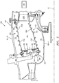
Figure 3 , thecombustor section 26 generally includes acombustor 50 with an outercombustor wall assembly 60, an innercombustor wall assembly 62 and adiffuser case 64. The outercombustor wall assembly 60 and the innercombustor wall assembly 62 are spaced apart such that acombustion chamber 66 is defined therebetween. Thecombustion chamber 66 may be generally annular in shape. - The outer
combustor liner assembly 60 is spaced radially inward from an outer diffuser case 64A of thediffuser case module 64 to define an outerannular plenum 76. The innercombustor liner assembly 62 is spaced radially outward from an inner diffuser case 64B of thediffuser case module 64 to define an innerannular plenum 78. It should be understood that although a particular combustor is illustrated, other combustor types with various combustor liner arrangements will also benefit herefrom. It should be further understood that the disclosed cooling flow paths are but an illustrated embodiment and should not be limited only thereto. - The combustor wall assemblies 60, 62 contain the combustion products for direction toward the
turbine section 28. Eachcombustor wall assembly respective support shell respective support shell forward liner panels 72A and a multiple ofaft liner panels 72B that are circumferentially staggered to line the hot side of theouter shell 68. A multiple offorward liner panels 74A and a multiple ofaft liner panels 74B are circumferentially staggered to line the hot side of theinner shell 70. - The
combustor 50 further includes aforward assembly 80 immediately downstream of thecompressor section 24 to receive compressed airflow therefrom. Theforward assembly 80 generally includes anannular hood 82 and abulkhead assembly 84 which locate a multiple of fuel nozzles 86 (one shown) and a multiple of swirlers 90 (one shown). Each of theswirlers 90 is mounted within an opening 92 of thebulkhead assembly 84 to be circumferentially aligned with one of a multiple ofannular hood ports 94. Eachbulkhead assembly 84 generally includes abulkhead support shell 96 secured to thecombustor wall assembly bulkhead liner panels 98 secured to thebulkhead support shell 96. - The
annular hood 82 extends radially between, and is secured to, the forwardmost ends of thecombustor wall assemblies annular hood 82 forms the multiple of circumferentiallydistributed hood ports 94 that accommodate therespective fuel nozzle 86 and introduce air into the forward end of thecombustion chamber 66. Eachfuel nozzle 86 may be secured to thediffuser case module 64 and project through one of thehood ports 94 and therespective swirler 90. - The
forward assembly 80 introduces core combustion air into the forward section of thecombustion chamber 66 while the remainder enters the outerannular plenum 76 and the innerannular plenum 78. The multiple offuel nozzles 86 and adjacent structure generate a blended fuel-air mixture that supports stable combustion in thecombustion chamber 66. - Opposite the
forward assembly 80, the outer andinner support shells NGVs 28A are static engine components which direct the combustion gases onto the turbine blades in theturbine section 28 to facilitate the conversion of pressure energy into kinetic energy. The combustion gases are also accelerated by theNGVs 28A because of their convergent shape and are typically given a "spin" or a "swirl" in the direction of turbine rotation. - With reference to
Figure 4 , eachfuel injector 86 generally includes afirst inlet 100 and asecond inlet 102 defined by aninlet housing 104, asupport housing 106 and anozzle assembly 108. Thefirst inlet 100 is transverse to thesecond inlet 102. Theinlet housing 104 is received within thesupport housing 106 and atube 110 extends through thehousings 102, 104 (Figure 5 ). - With reference to
Figure 5 , thefirst inlet 100 may receive a first fluid such as a liquid and thesecond inlet 102 may receive a second fluid such as a gas. Thefuel injector 86 in the disclosed non-limiting embodiment provides concentric passages for a liquid such as Jet-A, diesel, JP8, water and combinations thereof as well as a gas such as natural gas. Each of the fuels are communicated through separate concentric passages within thefuel injector 86 such thatgas turbine engine 20 readily operates on either fuel or combinations thereof. - The
tube 110 separates the liquid from the gas. Thetube 110 is secured within theinlet housing 104 with a seal such as an O-ring at oneend section 112 and at theopposite end section 114 in thenozzle assembly 108 via a braze, weld, thread or other attachment. Thetube 110 defines anannular gas passage 116 within thehousings tube 110. - With reference to
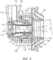
Figure 6 , thenozzle assembly 108 is at least partially received within theswirler 90 and generally includes anouter air swirler 120, aninner air swirler 122 and anair inflow tube 124 with ahelical inflow vane 126 along a nozzle axis F. Theouter wall 134 of theouter air swirler 120 includes a multiple ofaxial slots 135 which receive airflow therethrough. - An outer
annular air passage 128 is defined around axis F and within theouter air swirler 120. An annularfuel gas passage 130 is defined around axis F and between theouter air swirler 120 and theinner air swirler 122. The annularfuel gas passage 130 receives the fuel gas from within theannular gas passage 116 around thetube 110. Anannular liquid passage 132 is defined around axis F and within theinner air swirler 122. Theannular liquid passage 132 receives the liquid from within thetube 110. A central air passage 125 is defined along axis F within theair inflow tube 124. - The outer
annular air passage 128 is generally defined between theouter wall 134 and aninner wall 136 of theouter air swirler 120. Anend section 138 of theouter wall 134 extends beyond anend section 140 of theinner wall 136 and theannular liquid passage 132. Theend section 138 of theouter wall 134 includes aconvergent section 138A and adivergent section 138B. That is, theend section 138 defines a convergent-divergent nozzle with an essentially asymmetric hourglass-shape downstream of theinner air swirler 122 and theair inflow tube 124. - In one disclosed non-limiting embodiment, the
divergent section 138B defines an angle D of between about zero-thirty (0-30) degrees with respect to the nozzle axis F. Theend section 138 defines a length X which, in the disclosed non-limiting embodiment, is about 0-0.75 inches (0-19 mm) with a filming region R of about 0-0.4 inches (0-10 mm). That is, the length R defines from about 0 - 55 % of the length X. The filming region R may extend to adistal end 138C of thedivergent section 138B. It should be appreciated that various geometriesouter air swirler 120 will benefit herefrom. - The
end section 140 of theinner wall 136 abuts anouter wall 142 of theinner air swirler 122 to defines a multiple ofopenings 144 which in this disclosed non-limiting embodiment are skewed slots (best seen inFigure 7 ) to form an axial swirled exit for theannular gas passage 130. That is, theannular gas passage 130 terminates with the multiple ofopenings 144 direct the fuel gas axially and imparts a swirl thereto. In another disclosed non-limiting embodiment, theannular gas passage 130 terminates with a multiple of openings 144' that are generally circular passages (Figure 8 ). That is, the multiple of apertures 144'. It should be appreciated that other geometries may alternatively be provided. - The
annular gas passage 130 communicates essentially all, e.g., about one hundred (100) percent of the fuel gas through the multiple ofopenings 144. The multiple ofopenings 144 direct the fuel gas axially and imparts a swirl thereto. The multiple ofopenings 144 decrease the injection area and increase axial swirl momentum to increase circumferential uniformity, total air swirl due to the angle of gas injection and increase air stream mixing downstream of nozzle to facilitate fuel-air mixing. - Each of the multiple of
openings 144 in the disclosed non-limiting embodiment are skewed quadrilaterals in shape (best seen inFigure 7 ). In one disclosed non-limiting embodiment, the multiple ofopenings 144 are skewed at an angle α (Figure 9 ) between about fifty to sixty (50-60) degrees around the axis F. - The
outer wall 142 and aninner wall 146 of theinner air swirler 122 define theannular liquid passage 132. Anend section 148 of theouter wall 142 and anend section 150 of theinner wall 146 may be turned radially inward toward axis F to direct the liquid at least partially radially inward. - The
air inflow tube 124 is mounted within theinner wall 146 and includes the upstreamhelical inflow vane 126 to swirl the airflow therethrough. Due in part to the swirled airflow through theair inflow tube 124, the liquid spray expands from theannular liquid passage 132 and impacts upon the filing region R to re-film/re-atomize. The increased liquid injection recession causes large drops to re-film/re-atomization on larger wall surface, resulting smaller drop size and higher penetration which increasing water vaporization rate as well as positioning water in desirable location. The reduced water drop size and the effective utilization of water facilitates a decrease in NOx emissions with reduced water injection (i.e. lower water-to-fuel ratio) - With reference to
Figure 9 , each of the multiple ofopenings 144 are at least partially defined by avane 160 within the annularfuel gas passage 130. Eachvane 160 is defined by anairfoil wall surface 162 between aleading edge 164 and a trailingedge 166 to define a generally concave shaped portion to form apressure side 168 and a generally convex shaped portion forming asuction side 170. Eachvane 160 is angled with respect to the axis F at the aforementioned angle α of about fifty to sixty (50-60) degrees such that the trailingedge 166 thereof, theouter air swirler 120 and theinner air swirler 122 form the skewed quadrilateral exits of the openings 144 (Figure 7 ). - It should be understood that relative positional terms such as "forward," "aft," "upper," "lower," "above," "below," and the like are with reference to the normal operational attitude of the vehicle and should not be considered otherwise limiting.
- It should be understood that like reference numerals identify corresponding or similar elements throughout the several drawings. It should also be understood that although a particular component arrangement is disclosed in the illustrated embodiment, other arrangements will benefit herefrom.
- Although particular step sequences are shown, described, and claimed, it should be understood that steps may be performed in any order, separated or combined unless otherwise indicated and will still benefit from the present disclosure.
- The foregoing description is exemplary rather than defined by the limitations within. Various non-limiting embodiments are disclosed herein, however, one of ordinary skill in the art would recognize that various modifications and variations in light of the above teachings will fall within the scope of the appended claims. It is therefore to be understood that within the scope of the appended claims, the disclosure may be practiced other than as specifically described. For that reason the appended claims should be studied to determine true scope and content.
Claims (8)
- A fuel nozzle (86) for a combustor of a gas turbine engine comprising:
an outer air swirler (120) along an axis (F), said outer air swirler (120) defining an outer annular air passage (128) between an outer wall (134) and an inner wall (136), said outer wall (134) defines a convergent-divergent nozzle (138);
characterised by further comprising:an inner air swirler (122) along said axis to define an annular fuel gas passage (130) around said axis between said outer air swirler (120) and said inner air swirler (122);wherein said annular fuel gas passage (130) terminates with a multiple of openings (144) configured to direct the fuel gas axially and impart a swirl thereto; and by further comprising:a multiple of vanes (160) within the annular fuel gas passage (130), each of the multiple of vanes (160) being defined by an airfoil wall surface (162) between a leading edge (64) and a trailing edge (166) to define a generally concave shaped portion to form a pressure side (168) and a generally convex shaped portion forming a suction side (170), each of said multiple of vanes (160) being angled with respect to the axis (F) at an angle (x) of 50-60 degrees such that the trailing edges (166) thereof, the outer air swirler (120), and the inner air swirler (122) form skewed quadrilateral exits of the openings (144). - The fuel nozzle as recited in claim 1, wherein said outer wall (134) axially extends beyond said inner air swirler (122).
- The fuel nozzle as recited in claim 2, wherein said outer wall (134) defines a filming region from about 0 - 55 % of a length of said outer wall (134) axially beyond said inner air swirler (122).
- The fuel nozzle as recited in any preceding claim, wherein said outer wall (134) defines a divergent section (138B) at an angle of between 0-30 degrees with respect to said axis.
- The fuel nozzle as recited in claim 4, further comprising an air inflow tube (124) with a helical inflow vane (126) along said axis within said inner air swirler (122), said air inflow tube (124) defining a central air passage (125).
- The fuel nozzle as recited in claim 4 or 5, wherein said inner air swirler (122) defines an annular liquid passage (132) therebetween.
- The fuel nozzle as recited in claim 6, further comprising a tube (110) transverse to said inner air swirler (122) to transport a liquid therethrough.
- The fuel nozzle as recited in claim 7, wherein an end section of said annular liquid passage (132) is turned radially inward.
Applications Claiming Priority (2)
| Application Number | Priority Date | Filing Date | Title |
|---|---|---|---|
| US201361872363P | 2013-08-30 | 2013-08-30 | |
| PCT/US2014/051589 WO2015069354A2 (en) | 2013-08-30 | 2014-08-19 | Dual fuel nozzle with liquid filming atomization for a gas turbine engine |
Publications (3)
| Publication Number | Publication Date |
|---|---|
| EP3039345A2 EP3039345A2 (en) | 2016-07-06 |
| EP3039345A4 EP3039345A4 (en) | 2017-04-26 |
| EP3039345B1 true EP3039345B1 (en) | 2019-11-13 |
Family
ID=53042293
Family Applications (1)
| Application Number | Title | Priority Date | Filing Date |
|---|---|---|---|
| EP14859549.9A Active EP3039345B1 (en) | 2013-08-30 | 2014-08-19 | Dual fuel nozzle with liquid filming atomization for a gas turbine engine |
Country Status (3)
| Country | Link |
|---|---|
| US (1) | US10794596B2 (en) |
| EP (1) | EP3039345B1 (en) |
| WO (1) | WO2015069354A2 (en) |
Families Citing this family (14)
| Publication number | Priority date | Publication date | Assignee | Title |
|---|---|---|---|---|
| JP5924618B2 (en) * | 2012-06-07 | 2016-05-25 | 川崎重工業株式会社 | Fuel injection device |
| WO2015076883A2 (en) * | 2013-08-30 | 2015-05-28 | United Technologies Corporation | Dual fuel nozzle with swirling axial gas injection for a gas turbine engine |
| JP6535442B2 (en) * | 2014-08-18 | 2019-06-26 | 川崎重工業株式会社 | Fuel injection device |
| GB2543803B (en) * | 2015-10-29 | 2019-10-30 | Rolls Royce Plc | A combustion chamber assembly |
| US11619388B2 (en) * | 2017-12-21 | 2023-04-04 | Collins Engine Nozzles, Inc. | Dual fuel gas turbine engine pilot nozzles |
| US11378275B2 (en) * | 2019-12-06 | 2022-07-05 | Raytheon Technologies Corporation | High shear swirler with recessed fuel filmer for a gas turbine engine |
| US12007116B2 (en) | 2021-02-19 | 2024-06-11 | Pratt & Whitney Canada Corp. | Dual pressure fuel nozzles |
| US11525403B2 (en) | 2021-05-05 | 2022-12-13 | Pratt & Whitney Canada Corp. | Fuel nozzle with integrated metering and flashback system |
| US20220364509A1 (en) * | 2021-05-17 | 2022-11-17 | Pratt & Whitney Canada Corp. | Nozzle tip with shielded core for a dual combustion systems |
| US11906165B2 (en) * | 2021-12-21 | 2024-02-20 | General Electric Company | Gas turbine nozzle having an inner air swirler passage and plural exterior fuel passages |
| US12072099B2 (en) * | 2021-12-21 | 2024-08-27 | General Electric Company | Gas turbine fuel nozzle having a lip extending from the vanes of a swirler |
| DE102022207493A1 (en) * | 2022-07-21 | 2024-02-01 | Rolls-Royce Deutschland Ltd & Co Kg | Connection device for flow connection between a fuel supply system and a nozzle device, nozzle device and gas turbine arrangement |
| US11976820B2 (en) * | 2022-08-05 | 2024-05-07 | Rtx Corporation | Multi-fueled, water injected hydrogen fuel injector |
| US20240263795A1 (en) * | 2023-02-02 | 2024-08-08 | Pratt & Whitney Canada Corp. | Injector with swirler for hydrogen-driven gas turbine engine |
Family Cites Families (41)
| Publication number | Priority date | Publication date | Assignee | Title |
|---|---|---|---|---|
| GB1284439A (en) * | 1969-12-09 | 1972-08-09 | Rolls Royce | Fuel injector for a gas turbine engine |
| US3866413A (en) * | 1973-01-22 | 1975-02-18 | Parker Hannifin Corp | Air blast fuel atomizer |
| US3853273A (en) * | 1973-10-01 | 1974-12-10 | Gen Electric | Axial swirler central injection carburetor |
| US3980233A (en) * | 1974-10-07 | 1976-09-14 | Parker-Hannifin Corporation | Air-atomizing fuel nozzle |
| GB2016673B (en) * | 1978-03-18 | 1982-04-21 | Rolls Royce | Fuel injector |
| GB2035540B (en) * | 1978-11-23 | 1983-02-09 | Rolls Royce | Gas turbine engine fuel injector |
| GB2175993B (en) * | 1985-06-07 | 1988-12-21 | Rolls Royce | Improvements in or relating to dual fuel injectors |
| US5044559A (en) * | 1988-11-02 | 1991-09-03 | United Technologies Corporation | Gas assisted liquid atomizer |
| US4977740A (en) * | 1989-06-07 | 1990-12-18 | United Technologies Corporation | Dual fuel injector |
| US5505045A (en) | 1992-11-09 | 1996-04-09 | Fuel Systems Textron, Inc. | Fuel injector assembly with first and second fuel injectors and inner, outer, and intermediate air discharge chambers |
| US5339845A (en) * | 1993-07-26 | 1994-08-23 | Fuel Systems Textron, Inc. | Cleaning apparatus and method for fuel and other passages |
| US5423173A (en) * | 1993-07-29 | 1995-06-13 | United Technologies Corporation | Fuel injector and method of operating the fuel injector |
| GB9326367D0 (en) * | 1993-12-23 | 1994-02-23 | Rolls Royce Plc | Fuel injection apparatus |
| IT1313547B1 (en) * | 1999-09-23 | 2002-07-24 | Nuovo Pignone Spa | PRE-MIXING CHAMBER FOR GAS TURBINES |
| US6256995B1 (en) * | 1999-11-29 | 2001-07-10 | Pratt & Whitney Canada Corp. | Simple low cost fuel nozzle support |
| US6272840B1 (en) | 2000-01-13 | 2001-08-14 | Cfd Research Corporation | Piloted airblast lean direct fuel injector |
| US6381964B1 (en) * | 2000-09-29 | 2002-05-07 | General Electric Company | Multiple annular combustion chamber swirler having atomizing pilot |
| GB0025765D0 (en) * | 2000-10-20 | 2000-12-06 | Aero & Ind Technology Ltd | Fuel injector |
| US7028483B2 (en) * | 2003-07-14 | 2006-04-18 | Parker-Hannifin Corporation | Macrolaminate radial injector |
| US7000403B2 (en) * | 2004-03-12 | 2006-02-21 | Power Systems Mfg., Llc | Primary fuel nozzle having dual fuel capability |
| US8348180B2 (en) | 2004-06-09 | 2013-01-08 | Delavan Inc | Conical swirler for fuel injectors and combustor domes and methods of manufacturing the same |
| DE102004041272B4 (en) * | 2004-08-23 | 2017-07-13 | General Electric Technology Gmbh | Hybrid burner lance |
| US7779636B2 (en) * | 2005-05-04 | 2010-08-24 | Delavan Inc | Lean direct injection atomizer for gas turbine engines |
| US7540154B2 (en) * | 2005-08-11 | 2009-06-02 | Mitsubishi Heavy Industries, Ltd. | Gas turbine combustor |
| US7878000B2 (en) * | 2005-12-20 | 2011-02-01 | General Electric Company | Pilot fuel injector for mixer assembly of a high pressure gas turbine engine |
| US7631500B2 (en) * | 2006-09-29 | 2009-12-15 | General Electric Company | Methods and apparatus to facilitate decreasing combustor acoustics |
| US7926744B2 (en) * | 2008-02-21 | 2011-04-19 | Delavan Inc | Radially outward flowing air-blast fuel injector for gas turbine engine |
| US20090255258A1 (en) * | 2008-04-11 | 2009-10-15 | Delavan Inc | Pre-filming air-blast fuel injector having a reduced hydraulic spray angle |
| US20090255120A1 (en) * | 2008-04-11 | 2009-10-15 | General Electric Company | Method of assembling a fuel nozzle |
| US8215116B2 (en) * | 2008-10-02 | 2012-07-10 | General Electric Company | System and method for air-fuel mixing in gas turbines |
| JP4829315B2 (en) | 2009-01-16 | 2011-12-07 | 川崎重工業株式会社 | Fuel spray system for gas turbine engine |
| JP5472863B2 (en) | 2009-06-03 | 2014-04-16 | 独立行政法人 宇宙航空研究開発機構 | Staging fuel nozzle |
| FR2956897B1 (en) * | 2010-02-26 | 2012-07-20 | Snecma | INJECTION SYSTEM FOR TURBOMACHINE COMBUSTION CHAMBER, COMPRISING AIR INJECTION MEANS ENHANCING THE AIR-FUEL MIXTURE |
| US8418469B2 (en) * | 2010-09-27 | 2013-04-16 | General Electric Company | Fuel nozzle assembly for gas turbine system |
| US8726668B2 (en) * | 2010-12-17 | 2014-05-20 | General Electric Company | Fuel atomization dual orifice fuel nozzle |
| JP5924618B2 (en) * | 2012-06-07 | 2016-05-25 | 川崎重工業株式会社 | Fuel injection device |
| WO2014081334A1 (en) * | 2012-11-21 | 2014-05-30 | General Electric Company | Anti-coking liquid fuel cartridge |
| US9194583B2 (en) * | 2013-02-20 | 2015-11-24 | Jorge DE LA SOVERA | Mixed fuel vacuum burner-reactor |
| DE102014206139A1 (en) * | 2014-04-01 | 2015-10-01 | Siemens Aktiengesellschaft | burner head |
| US9791153B2 (en) * | 2015-02-27 | 2017-10-17 | United Technologies Corporation | Line replaceable fuel nozzle apparatus, system and method |
| US10132500B2 (en) * | 2015-10-16 | 2018-11-20 | Delavan Inc. | Airblast injectors |
-
2014
- 2014-08-19 WO PCT/US2014/051589 patent/WO2015069354A2/en active Application Filing
- 2014-08-19 US US14/914,825 patent/US10794596B2/en active Active
- 2014-08-19 EP EP14859549.9A patent/EP3039345B1/en active Active
Non-Patent Citations (1)
| Title |
|---|
| None * |
Also Published As
| Publication number | Publication date |
|---|---|
| US20160209037A1 (en) | 2016-07-21 |
| EP3039345A2 (en) | 2016-07-06 |
| EP3039345A4 (en) | 2017-04-26 |
| WO2015069354A2 (en) | 2015-05-14 |
| WO2015069354A3 (en) | 2015-07-16 |
| US10794596B2 (en) | 2020-10-06 |
Similar Documents
| Publication | Publication Date | Title |
|---|---|---|
| EP3039345B1 (en) | Dual fuel nozzle with liquid filming atomization for a gas turbine engine | |
| EP3039343B1 (en) | Dual fuel nozzle with swirling axial gas injection for a gas turbine engine and related method | |
| US10731861B2 (en) | Dual fuel nozzle with concentric fuel passages for a gas turbine engine | |
| US10465909B2 (en) | Mini mixing fuel nozzle assembly with mixing sleeve | |
| EP3306197B1 (en) | Dual fuel injector for a sequential burner of a sequential gas turbine | |
| CN113790463B (en) | Spiral case resident vortex combustor subassembly | |
| US20190024895A1 (en) | Combustor dilution structure for gas turbine engine | |
| CN110726157B (en) | Fuel nozzle cooling structure | |
| CN113357669B (en) | Fuel injector flow device | |
| US20180195725A1 (en) | Fuel nozzle assembly with micro channel cooling | |
| EP4317785A1 (en) | Dual-fuel fuel injector | |
| CN108019778B (en) | Fuel nozzle assembly with impingement purge | |
| US11226102B2 (en) | Fuel nozzle for a gas turbine engine | |
| CN116136308A (en) | Cyclone ferrule plate with pressure drop purge passage | |
| EP4317786A1 (en) | Liquid and hydrogen/methane fuel injector | |
| CN110805925B (en) | Mixer assembly for a combustor | |
| US10823416B2 (en) | Purge cooling structure for combustor assembly | |
| US10408455B2 (en) | Fuel nozzle assembly with fuel inlet slots | |
| US20230213194A1 (en) | Turbine engine fuel premixer | |
| CN114659136A (en) | Combustor for a gas turbine engine | |
| WO2014113105A2 (en) | Fuel nozzle for a gas turbine engine | |
| CN115200040A (en) | Dilution horn pair for gas turbine engine combustor |
Legal Events
| Date | Code | Title | Description |
|---|---|---|---|
| PUAI | Public reference made under article 153(3) epc to a published international application that has entered the european phase |
Free format text: ORIGINAL CODE: 0009012 |
|
| 17P | Request for examination filed |
Effective date: 20160329 |
|
| AK | Designated contracting states |
Kind code of ref document: A2 Designated state(s): AL AT BE BG CH CY CZ DE DK EE ES FI FR GB GR HR HU IE IS IT LI LT LU LV MC MK MT NL NO PL PT RO RS SE SI SK SM TR |
|
| AX | Request for extension of the european patent |
Extension state: BA ME |
|
| RIN1 | Information on inventor provided before grant (corrected) |
Inventor name: SNYDER, TIMOTHY S. Inventor name: KOPP-VAUGHAN, KRISTIN Inventor name: DAI, ZHONGTAO Inventor name: SMITH, RANDOLPH J. Inventor name: HAUTMAN, DONALD J. |
|
| RAP1 | Party data changed (applicant data changed or rights of an application transferred) |
Owner name: UNITED TECHNOLOGIES CORPORATION |
|
| DAX | Request for extension of the european patent (deleted) | ||
| A4 | Supplementary search report drawn up and despatched |
Effective date: 20170328 |
|
| RIC1 | Information provided on ipc code assigned before grant |
Ipc: F02C 7/22 20060101ALI20170322BHEP Ipc: F23R 3/28 20060101AFI20170322BHEP Ipc: F23R 3/02 20060101ALI20170322BHEP Ipc: F23R 3/36 20060101ALI20170322BHEP |
|
| STAA | Information on the status of an ep patent application or granted ep patent |
Free format text: STATUS: EXAMINATION IS IN PROGRESS |
|
| 17Q | First examination report despatched |
Effective date: 20180730 |
|
| GRAP | Despatch of communication of intention to grant a patent |
Free format text: ORIGINAL CODE: EPIDOSNIGR1 |
|
| STAA | Information on the status of an ep patent application or granted ep patent |
Free format text: STATUS: GRANT OF PATENT IS INTENDED |
|
| INTG | Intention to grant announced |
Effective date: 20190529 |
|
| GRAS | Grant fee paid |
Free format text: ORIGINAL CODE: EPIDOSNIGR3 |
|
| GRAA | (expected) grant |
Free format text: ORIGINAL CODE: 0009210 |
|
| STAA | Information on the status of an ep patent application or granted ep patent |
Free format text: STATUS: THE PATENT HAS BEEN GRANTED |
|
| AK | Designated contracting states |
Kind code of ref document: B1 Designated state(s): AL AT BE BG CH CY CZ DE DK EE ES FI FR GB GR HR HU IE IS IT LI LT LU LV MC MK MT NL NO PL PT RO RS SE SI SK SM TR |
|
| REG | Reference to a national code |
Ref country code: CH Ref legal event code: EP Ref country code: AT Ref legal event code: REF Ref document number: 1202048 Country of ref document: AT Kind code of ref document: T Effective date: 20191115 |
|
| REG | Reference to a national code |
Ref country code: DE Ref legal event code: R096 Ref document number: 602014056925 Country of ref document: DE |
|
| REG | Reference to a national code |
Ref country code: IE Ref legal event code: FG4D |
|
| REG | Reference to a national code |
Ref country code: NL Ref legal event code: MP Effective date: 20191113 |
|
| REG | Reference to a national code |
Ref country code: LT Ref legal event code: MG4D |
|
| PG25 | Lapsed in a contracting state [announced via postgrant information from national office to epo] |
Ref country code: PT Free format text: LAPSE BECAUSE OF FAILURE TO SUBMIT A TRANSLATION OF THE DESCRIPTION OR TO PAY THE FEE WITHIN THE PRESCRIBED TIME-LIMIT Effective date: 20200313 Ref country code: NO Free format text: LAPSE BECAUSE OF FAILURE TO SUBMIT A TRANSLATION OF THE DESCRIPTION OR TO PAY THE FEE WITHIN THE PRESCRIBED TIME-LIMIT Effective date: 20200213 Ref country code: BG Free format text: LAPSE BECAUSE OF FAILURE TO SUBMIT A TRANSLATION OF THE DESCRIPTION OR TO PAY THE FEE WITHIN THE PRESCRIBED TIME-LIMIT Effective date: 20200213 Ref country code: FI Free format text: LAPSE BECAUSE OF FAILURE TO SUBMIT A TRANSLATION OF THE DESCRIPTION OR TO PAY THE FEE WITHIN THE PRESCRIBED TIME-LIMIT Effective date: 20191113 Ref country code: LV Free format text: LAPSE BECAUSE OF FAILURE TO SUBMIT A TRANSLATION OF THE DESCRIPTION OR TO PAY THE FEE WITHIN THE PRESCRIBED TIME-LIMIT Effective date: 20191113 Ref country code: SE Free format text: LAPSE BECAUSE OF FAILURE TO SUBMIT A TRANSLATION OF THE DESCRIPTION OR TO PAY THE FEE WITHIN THE PRESCRIBED TIME-LIMIT Effective date: 20191113 Ref country code: NL Free format text: LAPSE BECAUSE OF FAILURE TO SUBMIT A TRANSLATION OF THE DESCRIPTION OR TO PAY THE FEE WITHIN THE PRESCRIBED TIME-LIMIT Effective date: 20191113 Ref country code: LT Free format text: LAPSE BECAUSE OF FAILURE TO SUBMIT A TRANSLATION OF THE DESCRIPTION OR TO PAY THE FEE WITHIN THE PRESCRIBED TIME-LIMIT Effective date: 20191113 Ref country code: PL Free format text: LAPSE BECAUSE OF FAILURE TO SUBMIT A TRANSLATION OF THE DESCRIPTION OR TO PAY THE FEE WITHIN THE PRESCRIBED TIME-LIMIT Effective date: 20191113 Ref country code: GR Free format text: LAPSE BECAUSE OF FAILURE TO SUBMIT A TRANSLATION OF THE DESCRIPTION OR TO PAY THE FEE WITHIN THE PRESCRIBED TIME-LIMIT Effective date: 20200214 |
|
| PG25 | Lapsed in a contracting state [announced via postgrant information from national office to epo] |
Ref country code: HR Free format text: LAPSE BECAUSE OF FAILURE TO SUBMIT A TRANSLATION OF THE DESCRIPTION OR TO PAY THE FEE WITHIN THE PRESCRIBED TIME-LIMIT Effective date: 20191113 Ref country code: IS Free format text: LAPSE BECAUSE OF FAILURE TO SUBMIT A TRANSLATION OF THE DESCRIPTION OR TO PAY THE FEE WITHIN THE PRESCRIBED TIME-LIMIT Effective date: 20200313 Ref country code: RS Free format text: LAPSE BECAUSE OF FAILURE TO SUBMIT A TRANSLATION OF THE DESCRIPTION OR TO PAY THE FEE WITHIN THE PRESCRIBED TIME-LIMIT Effective date: 20191113 |
|
| PG25 | Lapsed in a contracting state [announced via postgrant information from national office to epo] |
Ref country code: AL Free format text: LAPSE BECAUSE OF FAILURE TO SUBMIT A TRANSLATION OF THE DESCRIPTION OR TO PAY THE FEE WITHIN THE PRESCRIBED TIME-LIMIT Effective date: 20191113 |
|
| PG25 | Lapsed in a contracting state [announced via postgrant information from national office to epo] |
Ref country code: DK Free format text: LAPSE BECAUSE OF FAILURE TO SUBMIT A TRANSLATION OF THE DESCRIPTION OR TO PAY THE FEE WITHIN THE PRESCRIBED TIME-LIMIT Effective date: 20191113 Ref country code: EE Free format text: LAPSE BECAUSE OF FAILURE TO SUBMIT A TRANSLATION OF THE DESCRIPTION OR TO PAY THE FEE WITHIN THE PRESCRIBED TIME-LIMIT Effective date: 20191113 Ref country code: RO Free format text: LAPSE BECAUSE OF FAILURE TO SUBMIT A TRANSLATION OF THE DESCRIPTION OR TO PAY THE FEE WITHIN THE PRESCRIBED TIME-LIMIT Effective date: 20191113 Ref country code: CZ Free format text: LAPSE BECAUSE OF FAILURE TO SUBMIT A TRANSLATION OF THE DESCRIPTION OR TO PAY THE FEE WITHIN THE PRESCRIBED TIME-LIMIT Effective date: 20191113 Ref country code: ES Free format text: LAPSE BECAUSE OF FAILURE TO SUBMIT A TRANSLATION OF THE DESCRIPTION OR TO PAY THE FEE WITHIN THE PRESCRIBED TIME-LIMIT Effective date: 20191113 |
|
| REG | Reference to a national code |
Ref country code: DE Ref legal event code: R097 Ref document number: 602014056925 Country of ref document: DE |
|
| REG | Reference to a national code |
Ref country code: AT Ref legal event code: MK05 Ref document number: 1202048 Country of ref document: AT Kind code of ref document: T Effective date: 20191113 |
|
| PG25 | Lapsed in a contracting state [announced via postgrant information from national office to epo] |
Ref country code: SM Free format text: LAPSE BECAUSE OF FAILURE TO SUBMIT A TRANSLATION OF THE DESCRIPTION OR TO PAY THE FEE WITHIN THE PRESCRIBED TIME-LIMIT Effective date: 20191113 Ref country code: SK Free format text: LAPSE BECAUSE OF FAILURE TO SUBMIT A TRANSLATION OF THE DESCRIPTION OR TO PAY THE FEE WITHIN THE PRESCRIBED TIME-LIMIT Effective date: 20191113 |
|
| PLBE | No opposition filed within time limit |
Free format text: ORIGINAL CODE: 0009261 |
|
| STAA | Information on the status of an ep patent application or granted ep patent |
Free format text: STATUS: NO OPPOSITION FILED WITHIN TIME LIMIT |
|
| 26N | No opposition filed |
Effective date: 20200814 |
|
| PG25 | Lapsed in a contracting state [announced via postgrant information from national office to epo] |
Ref country code: AT Free format text: LAPSE BECAUSE OF FAILURE TO SUBMIT A TRANSLATION OF THE DESCRIPTION OR TO PAY THE FEE WITHIN THE PRESCRIBED TIME-LIMIT Effective date: 20191113 Ref country code: SI Free format text: LAPSE BECAUSE OF FAILURE TO SUBMIT A TRANSLATION OF THE DESCRIPTION OR TO PAY THE FEE WITHIN THE PRESCRIBED TIME-LIMIT Effective date: 20191113 |
|
| PG25 | Lapsed in a contracting state [announced via postgrant information from national office to epo] |
Ref country code: IT Free format text: LAPSE BECAUSE OF FAILURE TO SUBMIT A TRANSLATION OF THE DESCRIPTION OR TO PAY THE FEE WITHIN THE PRESCRIBED TIME-LIMIT Effective date: 20191113 |
|
| PG25 | Lapsed in a contracting state [announced via postgrant information from national office to epo] |
Ref country code: MC Free format text: LAPSE BECAUSE OF FAILURE TO SUBMIT A TRANSLATION OF THE DESCRIPTION OR TO PAY THE FEE WITHIN THE PRESCRIBED TIME-LIMIT Effective date: 20191113 |
|
| REG | Reference to a national code |
Ref country code: CH Ref legal event code: PL |
|
| PG25 | Lapsed in a contracting state [announced via postgrant information from national office to epo] |
Ref country code: CH Free format text: LAPSE BECAUSE OF NON-PAYMENT OF DUE FEES Effective date: 20200831 Ref country code: LU Free format text: LAPSE BECAUSE OF NON-PAYMENT OF DUE FEES Effective date: 20200819 Ref country code: LI Free format text: LAPSE BECAUSE OF NON-PAYMENT OF DUE FEES Effective date: 20200831 |
|
| REG | Reference to a national code |
Ref country code: BE Ref legal event code: MM Effective date: 20200831 |
|
| PG25 | Lapsed in a contracting state [announced via postgrant information from national office to epo] |
Ref country code: IE Free format text: LAPSE BECAUSE OF NON-PAYMENT OF DUE FEES Effective date: 20200819 Ref country code: BE Free format text: LAPSE BECAUSE OF NON-PAYMENT OF DUE FEES Effective date: 20200831 |
|
| PG25 | Lapsed in a contracting state [announced via postgrant information from national office to epo] |
Ref country code: TR Free format text: LAPSE BECAUSE OF FAILURE TO SUBMIT A TRANSLATION OF THE DESCRIPTION OR TO PAY THE FEE WITHIN THE PRESCRIBED TIME-LIMIT Effective date: 20191113 Ref country code: MT Free format text: LAPSE BECAUSE OF FAILURE TO SUBMIT A TRANSLATION OF THE DESCRIPTION OR TO PAY THE FEE WITHIN THE PRESCRIBED TIME-LIMIT Effective date: 20191113 Ref country code: CY Free format text: LAPSE BECAUSE OF FAILURE TO SUBMIT A TRANSLATION OF THE DESCRIPTION OR TO PAY THE FEE WITHIN THE PRESCRIBED TIME-LIMIT Effective date: 20191113 |
|
| PG25 | Lapsed in a contracting state [announced via postgrant information from national office to epo] |
Ref country code: MK Free format text: LAPSE BECAUSE OF FAILURE TO SUBMIT A TRANSLATION OF THE DESCRIPTION OR TO PAY THE FEE WITHIN THE PRESCRIBED TIME-LIMIT Effective date: 20191113 |
|
| REG | Reference to a national code |
Ref country code: DE Ref legal event code: R081 Ref document number: 602014056925 Country of ref document: DE Owner name: RAYTHEON TECHNOLOGIES CORPORATION (N.D.GES.D.S, US Free format text: FORMER OWNER: UNITED TECHNOLOGIES CORPORATION, FARMINGTON, CONN., US |
|
| P01 | Opt-out of the competence of the unified patent court (upc) registered |
Effective date: 20230520 |
|
| PGFP | Annual fee paid to national office [announced via postgrant information from national office to epo] |
Ref country code: GB Payment date: 20230720 Year of fee payment: 10 |
|
| PGFP | Annual fee paid to national office [announced via postgrant information from national office to epo] |
Ref country code: FR Payment date: 20230720 Year of fee payment: 10 Ref country code: DE Payment date: 20230720 Year of fee payment: 10 |