EP3321588B1 - Combustor for a gas turbine engine - Google Patents
Combustor for a gas turbine engine Download PDFInfo
- Publication number
- EP3321588B1 EP3321588B1 EP17201213.0A EP17201213A EP3321588B1 EP 3321588 B1 EP3321588 B1 EP 3321588B1 EP 17201213 A EP17201213 A EP 17201213A EP 3321588 B1 EP3321588 B1 EP 3321588B1
- Authority
- EP
- European Patent Office
- Prior art keywords
- aft
- combustor
- liner
- circumferential edge
- linear
- Prior art date
- Legal status (The legal status is an assumption and is not a legal conclusion. Google has not performed a legal analysis and makes no representation as to the accuracy of the status listed.)
- Active
Links
- 238000010790 dilution Methods 0.000 claims description 33
- 239000012895 dilution Substances 0.000 claims description 33
- 238000001816 cooling Methods 0.000 claims description 15
- 230000000295 complement effect Effects 0.000 claims description 3
- 239000007789 gas Substances 0.000 description 17
- 238000002485 combustion reaction Methods 0.000 description 16
- 239000000446 fuel Substances 0.000 description 10
- 239000000567 combustion gas Substances 0.000 description 4
- 238000013461 design Methods 0.000 description 4
- 230000008901 benefit Effects 0.000 description 3
- 230000003068 static effect Effects 0.000 description 3
- PXHVJJICTQNCMI-UHFFFAOYSA-N Nickel Chemical compound [Ni] PXHVJJICTQNCMI-UHFFFAOYSA-N 0.000 description 2
- 230000002411 adverse Effects 0.000 description 2
- 230000000712 assembly Effects 0.000 description 2
- 238000000429 assembly Methods 0.000 description 2
- 230000005540 biological transmission Effects 0.000 description 2
- 230000009977 dual effect Effects 0.000 description 2
- 230000009467 reduction Effects 0.000 description 2
- 239000004215 Carbon black (E152) Substances 0.000 description 1
- 238000003491 array Methods 0.000 description 1
- 230000004323 axial length Effects 0.000 description 1
- 230000015572 biosynthetic process Effects 0.000 description 1
- 239000000919 ceramic Substances 0.000 description 1
- 238000006243 chemical reaction Methods 0.000 description 1
- 238000004891 communication Methods 0.000 description 1
- 230000006835 compression Effects 0.000 description 1
- 238000007906 compression Methods 0.000 description 1
- 238000012937 correction Methods 0.000 description 1
- 230000001419 dependent effect Effects 0.000 description 1
- 229930195733 hydrocarbon Natural products 0.000 description 1
- 150000002430 hydrocarbons Chemical class 0.000 description 1
- 238000002347 injection Methods 0.000 description 1
- 239000007924 injection Substances 0.000 description 1
- 239000000463 material Substances 0.000 description 1
- 238000005259 measurement Methods 0.000 description 1
- 239000002184 metal Substances 0.000 description 1
- 229910052751 metal Inorganic materials 0.000 description 1
- 229910001092 metal group alloy Inorganic materials 0.000 description 1
- 239000000203 mixture Substances 0.000 description 1
- 238000012986 modification Methods 0.000 description 1
- 230000004048 modification Effects 0.000 description 1
- 239000003607 modifier Substances 0.000 description 1
- 229910052759 nickel Inorganic materials 0.000 description 1
- 238000004806 packaging method and process Methods 0.000 description 1
- 238000010791 quenching Methods 0.000 description 1
- 238000009419 refurbishment Methods 0.000 description 1
- 230000008439 repair process Effects 0.000 description 1
- 230000004044 response Effects 0.000 description 1
- 229910000601 superalloy Inorganic materials 0.000 description 1
- 238000012546 transfer Methods 0.000 description 1
- 230000007704 transition Effects 0.000 description 1
- 238000011144 upstream manufacturing Methods 0.000 description 1
Images


Classifications
-
- F—MECHANICAL ENGINEERING; LIGHTING; HEATING; WEAPONS; BLASTING
- F23—COMBUSTION APPARATUS; COMBUSTION PROCESSES
- F23M—CASINGS, LININGS, WALLS OR DOORS SPECIALLY ADAPTED FOR COMBUSTION CHAMBERS, e.g. FIREBRIDGES; DEVICES FOR DEFLECTING AIR, FLAMES OR COMBUSTION PRODUCTS IN COMBUSTION CHAMBERS; SAFETY ARRANGEMENTS SPECIALLY ADAPTED FOR COMBUSTION APPARATUS; DETAILS OF COMBUSTION CHAMBERS, NOT OTHERWISE PROVIDED FOR
- F23M5/00—Casings; Linings; Walls
- F23M5/04—Supports for linings
-
- F—MECHANICAL ENGINEERING; LIGHTING; HEATING; WEAPONS; BLASTING
- F23—COMBUSTION APPARATUS; COMBUSTION PROCESSES
- F23R—GENERATING COMBUSTION PRODUCTS OF HIGH PRESSURE OR HIGH VELOCITY, e.g. GAS-TURBINE COMBUSTION CHAMBERS
- F23R3/00—Continuous combustion chambers using liquid or gaseous fuel
- F23R3/002—Wall structures
-
- F—MECHANICAL ENGINEERING; LIGHTING; HEATING; WEAPONS; BLASTING
- F01—MACHINES OR ENGINES IN GENERAL; ENGINE PLANTS IN GENERAL; STEAM ENGINES
- F01D—NON-POSITIVE DISPLACEMENT MACHINES OR ENGINES, e.g. STEAM TURBINES
- F01D9/00—Stators
- F01D9/02—Nozzles; Nozzle boxes; Stator blades; Guide conduits, e.g. individual nozzles
- F01D9/023—Transition ducts between combustor cans and first stage of the turbine in gas-turbine engines; their cooling or sealings
-
- F—MECHANICAL ENGINEERING; LIGHTING; HEATING; WEAPONS; BLASTING
- F23—COMBUSTION APPARATUS; COMBUSTION PROCESSES
- F23M—CASINGS, LININGS, WALLS OR DOORS SPECIALLY ADAPTED FOR COMBUSTION CHAMBERS, e.g. FIREBRIDGES; DEVICES FOR DEFLECTING AIR, FLAMES OR COMBUSTION PRODUCTS IN COMBUSTION CHAMBERS; SAFETY ARRANGEMENTS SPECIALLY ADAPTED FOR COMBUSTION APPARATUS; DETAILS OF COMBUSTION CHAMBERS, NOT OTHERWISE PROVIDED FOR
- F23M5/00—Casings; Linings; Walls
- F23M5/08—Cooling thereof; Tube walls
- F23M5/085—Cooling thereof; Tube walls using air or other gas as the cooling medium
-
- F—MECHANICAL ENGINEERING; LIGHTING; HEATING; WEAPONS; BLASTING
- F23—COMBUSTION APPARATUS; COMBUSTION PROCESSES
- F23R—GENERATING COMBUSTION PRODUCTS OF HIGH PRESSURE OR HIGH VELOCITY, e.g. GAS-TURBINE COMBUSTION CHAMBERS
- F23R3/00—Continuous combustion chambers using liquid or gaseous fuel
- F23R3/02—Continuous combustion chambers using liquid or gaseous fuel characterised by the air-flow or gas-flow configuration
- F23R3/04—Air inlet arrangements
- F23R3/06—Arrangement of apertures along the flame tube
-
- F—MECHANICAL ENGINEERING; LIGHTING; HEATING; WEAPONS; BLASTING
- F23—COMBUSTION APPARATUS; COMBUSTION PROCESSES
- F23R—GENERATING COMBUSTION PRODUCTS OF HIGH PRESSURE OR HIGH VELOCITY, e.g. GAS-TURBINE COMBUSTION CHAMBERS
- F23R3/00—Continuous combustion chambers using liquid or gaseous fuel
- F23R3/42—Continuous combustion chambers using liquid or gaseous fuel characterised by the arrangement or form of the flame tubes or combustion chambers
- F23R3/50—Combustion chambers comprising an annular flame tube within an annular casing
-
- F—MECHANICAL ENGINEERING; LIGHTING; HEATING; WEAPONS; BLASTING
- F23—COMBUSTION APPARATUS; COMBUSTION PROCESSES
- F23R—GENERATING COMBUSTION PRODUCTS OF HIGH PRESSURE OR HIGH VELOCITY, e.g. GAS-TURBINE COMBUSTION CHAMBERS
- F23R3/00—Continuous combustion chambers using liquid or gaseous fuel
- F23R3/42—Continuous combustion chambers using liquid or gaseous fuel characterised by the arrangement or form of the flame tubes or combustion chambers
- F23R3/60—Support structures; Attaching or mounting means
-
- F—MECHANICAL ENGINEERING; LIGHTING; HEATING; WEAPONS; BLASTING
- F23—COMBUSTION APPARATUS; COMBUSTION PROCESSES
- F23R—GENERATING COMBUSTION PRODUCTS OF HIGH PRESSURE OR HIGH VELOCITY, e.g. GAS-TURBINE COMBUSTION CHAMBERS
- F23R2900/00—Special features of, or arrangements for continuous combustion chambers; Combustion processes therefor
- F23R2900/03041—Effusion cooled combustion chamber walls or domes
-
- F—MECHANICAL ENGINEERING; LIGHTING; HEATING; WEAPONS; BLASTING
- F23—COMBUSTION APPARATUS; COMBUSTION PROCESSES
- F23R—GENERATING COMBUSTION PRODUCTS OF HIGH PRESSURE OR HIGH VELOCITY, e.g. GAS-TURBINE COMBUSTION CHAMBERS
- F23R2900/00—Special features of, or arrangements for continuous combustion chambers; Combustion processes therefor
- F23R2900/03042—Film cooled combustion chamber walls or domes
-
- F—MECHANICAL ENGINEERING; LIGHTING; HEATING; WEAPONS; BLASTING
- F23—COMBUSTION APPARATUS; COMBUSTION PROCESSES
- F23R—GENERATING COMBUSTION PRODUCTS OF HIGH PRESSURE OR HIGH VELOCITY, e.g. GAS-TURBINE COMBUSTION CHAMBERS
- F23R2900/00—Special features of, or arrangements for continuous combustion chambers; Combustion processes therefor
- F23R2900/03044—Impingement cooled combustion chamber walls or subassemblies
Definitions
- the present disclosure relates to a gas turbine engine and, more particularly, to a combustor section therefor.
- Gas turbine engines such as those that power modern commercial and military aircraft, generally include a compressor section to pressurize an airflow, a combustor section to burn a hydrocarbon fuel in the presence of the pressurized air, and a turbine section to extract energy from the resultant combustion gases.
- the combustor section typically includes a combustion chamber formed by an inner and outer wall assembly.
- Each wall assembly includes a support shell lined with heat shields often referred to as liner panels.
- Combustor panels are often employed in modern annular gas turbine combustors to form the inner flow path. The panels are part of a two-wall liner and are exposed to a thermally challenging environment.
- combustor Impingement Film-Cooled Floatwall (IFF) liner panels typically include a hot side exposed to the gas path.
- the opposite, or cold side has features such as cast in threaded studs to mount the liner panel and a full perimeter rail that contact the inner surface of the liner shells.
- Combustor panels typically have a quadrilateral projection (i.e. rectangular or trapezoid) when viewed from the hot surface.
- the panels have a straight edge that forms the front or upstream edge of the panel and a second straight edge that forms the back or downstream edge of the combustor.
- the panels also have side edges that are linear in profile.
- the liner panels extend over an arc in a conical or cylindrical fashion in a plane and terminate in regions where the combustor geometry transitions, diverges, or converges. This may contribute to durability and flow path concerns where forward and aft panels merge or form interfaces. These areas can be prone to steps between panels, dead regions, cooling challenges and adverse local aerodynamics.
- US 4,302,941 discloses a prior art combustor as set forth in the preamble of claim 1.
- US 2016/109129 A1 discloses a prior art heat shield tile for a heat shield of a combustion chamber.
- the invention provides a combustor as recited in claim 1.
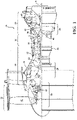
- FIG. 1 schematically illustrates a gas turbine engine 20.
- the gas turbine engine 20 is disclosed herein as a two-spool turbo fan that generally incorporates a fan section 22, a compressor section 24, a combustor section 26 and a turbine section 28.
- Alternative engine architectures might include an augmentor section among other systems or features.
- the fan section 22 drives air along a bypass flowpath and into the compressor section 24.
- the compressor section 24 drives air along a core flowpath for compression and communication into the combustor section 26, which then expands and directs the air through the turbine section 28.
- turbofan in the disclosed non-limiting embodiment, it should be appreciated that the concepts described herein are not limited to use with turbofans as the teachings may be applied to other types of turbine engines such as a turbojets, turboshafts, and three-spool (plus fan) turbofans wherein an intermediate spool includes an Intermediate Pressure Compressor ("IPC") between a Low Pressure Compressor (“LPC”) and a High Pressure Compressor (“HPC”), and an Intermediate Pressure Turbine (“IPT”) between the High Pressure Turbine (“HPT”) and the Low Pressure Turbine (“LPT”).
- IPC Intermediate Pressure Compressor
- LPC Low Pressure Compressor
- HPC High Pressure Compressor
- IPT Intermediate Pressure Turbine
- the engine 20 generally includes a low spool 30 and a high spool 32 mounted for rotation about an engine central longitudinal axis A relative to an engine static structure 36 via several bearing structures 38.
- the low spool 30 generally includes an inner shaft 40 that interconnects a fan 42, a Low Pressure Compressor (“LPC”) 44 and a Low Pressure Turbine (“LPT”) 46.
- the inner shaft 40 drives the fan 42 directly or through a geared architecture 48 to drive the fan 42 at a lower speed than the low spool 30.
- An exemplary reduction transmission is an epicyclic transmission, namely a planetary or star gear system.
- the high spool 32 includes an outer shaft 50 that interconnects a High Pressure Compressor ("HPC") 52 and High Pressure Turbine (“HPT”) 54.
- a combustor 56 is arranged between the HPC 52 and the HPT 54.
- the inner shaft 40 and the outer shaft 50 are concentric and rotate about the engine central longitudinal axis A which is collinear with their longitudinal axes.
- Core airflow is compressed by the LPC 44, then the HPC 52, mixed with the fuel and burned in the combustor 56, then expanded over the HPT 54 and the LPT 46.
- the LPT 46 and HPT 54 rotationally drive the respective low spool 30 and high spool 32 in response to the expansion.
- the main engine shafts 40, 50 are supported at a plurality of points by bearing systems 38 within the static structure 36.
- the gas turbine engine 20 is a high-bypass geared aircraft engine.
- the gas turbine engine 20 bypass ratio is greater than about six.
- the geared architecture 48 can include an epicyclic gear train, such as a planetary gear system or other gear system.
- the example epicyclic gear train has a gear reduction ratio of greater than about 2.3, and in another example is greater than about 2.5:1.
- the geared turbofan enables operation of the low spool 30 at higher speeds which can increase the operational efficiency of the LPC 44 and LPT 46 and render increased pressure in a fewer number of stages.
- a pressure ratio associated with the LPT 46 is pressure measured prior to the inlet of the LPT 46 as related to the pressure at the outlet of the LPT 46 prior to an exhaust nozzle of the gas turbine engine 20.
- the bypass ratio of the gas turbine engine 20 is greater than about ten
- the fan diameter is significantly larger than that of the LPC 44
- the LPT 46 has a pressure ratio that is greater than about five. It should be appreciated, however, that the above parameters are only exemplary of one embodiment of a geared architecture engine and that the present disclosure is applicable to other gas turbine engines including direct drive turbofans.
- a significant amount of thrust is provided by the bypass flow due to the high bypass ratio.
- the fan section 22 of the gas turbine engine 20 is designed for a particular flight condition - typically cruise at about 0.8 Mach and about 35,000 feet (10,668m). This flight condition, with the gas turbine engine 20 at its best fuel consumption, is also known as bucket cruise Thrust Specific Fuel Consumption (TSFC).
- TSFC Thrust Specific Fuel Consumption
- Fan Pressure Ratio is the pressure ratio across a blade of the fan section 22 without the use of a Fan Exit Guide Vane system.
- the low Fan Pressure Ratio according to one non-limiting embodiment of the example gas turbine engine 20 is less than 1.45.
- the Low Corrected Fan Tip Speed according to one non-limiting embodiment of the example gas turbine engine 20 is less than about 1150 fps (351 m/s).
- the combustor section 26 generally includes a combustor 56 with an outer combustor wall assembly 60, an inner combustor wall assembly 62, and a diffuser case module 64.
- the outer combustor wall assembly 60 and the inner combustor wall assembly 62 are spaced apart such that a combustion chamber 66 is defined therebetween.
- the combustion chamber 66 is generally annular in shape to surround the engine central longitudinal axis A.
- the outer combustor liner assembly 60 is spaced radially inward from an outer diffuser case 64A of the diffuser case module 64 to define an outer annular plenum 76.
- the inner combustor liner assembly 62 is spaced radially outward from an inner diffuser case 64B of the diffuser case module 64 to define an inner annular plenum 78. It should be appreciated that although a particular combustor is illustrated, other combustor types with various combustor liner arrangements will also benefit herefrom. It should be further appreciated that the disclosed cooling flow paths are but an illustrated embodiment and should not be limited only thereto.
- the combustor wall assemblies 60, 62 contain the combustion products for direction toward the turbine section 28.
- Each combustor wall assembly 60, 62 generally includes a respective support shell 68, 70 which supports one or more liner panels 72, 74 mounted thereto arranged to form a liner array.
- the support shells 68, 70 may be manufactured by, for example, the hydroforming of a sheet metal alloy to provide the generally cylindrical outer shell 68 and inner shell 70.
- Each of the liner panels 72, 74 may be generally rectilinear with a circumferential arc.
- the liner panels 72, 74 may be manufactured of, for example, a nickel based super alloy, ceramic or other temperature resistant material.
- the liner array includes a multiple of forward liner panels 72A and a multiple of aft liner panels 74A that are circumferentially staggered to line the outer shell 68.
- a multiple of forward liner panels 72B and a multiple of aft liner panels 74B are circumferentially staggered to line the inner shell 70.
- the combustor 56 further includes a forward assembly 80 immediately downstream of the compressor section 24 to receive compressed airflow therefrom.
- the forward assembly 80 generally includes a cowl 82, a bulkhead assembly 84, and a multiple of swirlers 90 (one shown). Each of the swirlers 90 is circumferentially aligned with one of a multiple of fuel nozzles 86 (one shown) and the respective hood ports 94 to project through the bulkhead assembly 84.
- the bulkhead assembly 84 includes a bulkhead support shell 96 secured to the combustor walls 60, 62, and a multiple of circumferentially distributed bulkhead liner panels 98 secured to the bulkhead support shell 96 around the swirler opening.
- the bulkhead support shell 96 is generally annular and the multiple of circumferentially distributed bulkhead liner panels 98 are segmented, typically one to each fuel nozzle 86 and swirler 90.
- the cowl 82 extends radially between, and is secured to, the forwardmost ends of the combustor walls 60, 62.
- the cowl 82 includes a multiple of circumferentially distributed hood ports 94 that receive one of the respective multiple of fuel nozzles 86 and facilitates the direction of compressed air into the forward end of the combustion chamber 66 through a swirler opening 92.
- Each fuel nozzle 86 may be secured to the diffuser case module 64 and project through one of the hood ports 94 and through the swirler opening 92 within the respective swirler 90.
- the forward assembly 80 introduces core combustion air into the forward section of the combustion chamber 66 while the remainder enters the outer annular plenum 76 and the inner annular plenum 78.
- the multiple of fuel nozzles 86 and adjacent structure generate a blended fuel-air mixture that supports stable combustion in the combustion chamber 66.
- the outer and inner support shells 68, 70 are mounted to a first row of Nozzle Guide Vanes (NGVs) 54A in the HPT 54.
- the NGVs 54A are static engine components which direct core airflow combustion gases onto the turbine blades of the first turbine rotor in the turbine section 28 to facilitate the conversion of pressure energy into kinetic energy.
- the core airflow combustion gases are also accelerated by the NGVs 54A because of their convergent shape and are typically given a "spin” or a "swirl” in the direction of turbine rotor rotation.
- the turbine rotor blades absorb this energy to drive the turbine rotor at high speed.
- a multiple of studs 100 extend from each of the liner panels 72, 74 so as to permit a liner array (partially shown in FIG. 4 ) of the liner panels 72, 74 to be mounted to their respective support shells 68, 70 with fasteners 102 such as nuts. That is, the studs 100 project rigidly from the liner panels 72, 74 to extend through the respective support shells 68, 70 and receive the fasteners 102 on a threaded section thereof ( FIG. 5 ).
- a multiple of cooling impingement passages 104 penetrate through the support shells 68, 70 to allow air from the respective annular plenums 76, 78 to enter cavities 106 formed in the combustor walls 60, 62 between the respective support shells 68, 70 and liner panels 72, 74.
- the impingement passages 104 are generally normal to the surface of the liner panels 72, 74.
- the air in the cavities 106 provides cold side impingement cooling of the liner panels 72, 74 that is generally defined herein as heat removal via internal convection.
- a multiple of effusion passages 108 penetrate through each of the liner panels 72, 74.
- the geometry of the passages e.g., diameter, shape, density, surface arcuate surface, incidence arcuate surface, etc., as well as the location of the passages with respect to the high temperature combustion flow also contributes to effusion cooling.
- the effusion passages 108 allow the air to pass from the cavities 106 defined in part by a cold side 110 of the liner panels 72, 74 to a hot side 112 of the liner panels 72, 74 and thereby facilitate the formation of a thin, relatively cool, film of cooling air along the hot side 112.
- each of the multiple of effusion passages 108 are typically 0.025" (0.635 mm) in diameter and define a surface arcuate surface section of about thirty (30) degrees with respect to the cold side 110 of the liner panels 72, 74.
- the effusion passages 108 are generally more numerous than the impingement passages 104 and promote film cooling along the hot side 112 to sheath the liner panels 72, 74 ( FIG. 6 ).
- Film cooling as defined herein is the introduction of a relatively cooler air at one or more discrete locations along a surface exposed to a high temperature environment to protect that surface in the region of the air injection as well as downstream thereof.
- impingement passages 104 and effusion passages 108 may be referred to as an Impingement Film Floatwall (IFF) assembly.
- IFF Impingement Film Floatwall
- a multiple of dilution passages 116 are located in the liner panels 72, 74 each along a common axis D.
- the dilution passages 116 are located in a circumferential line W (shown partially in FIG. 4 ).
- the dilution passages 116 are illustrated in the disclosed non-limiting embodiment as within the aft liner panels 74A, 74B, the dilution passages may alternatively be located in the forward liner panels 72A, 72B or in a single liner panel which replaces the fore/aft liner panel array.
- the dilution passages 116 although illustrated in the disclosed non-limiting embodiment as integrally formed in the liner panels, it should be appreciated that the dilution passages 116 may be separate components. Whether integrally formed or separate components, the dilution passages 116 may be referred to as grommets.
- each of the forward liner panels 72A, 72B, and the aft liner panels 74A, 74B in the liner panel array includes a perimeter rail 120a, 120b formed adjacent to a forward circumferential edge 122a, 122b, an aft circumferential edge 124a, 124b, and axial edges 126Aa 126Ab, 126Ba, 126Bb, that interconnect the forward and aft circumferential edge 122a, 122b, 124a, 124b.
- the perimeter rail 120a, 120b is located adjacent to the edge of the respective forward liner panels 72A, 72B, and the aft liner panels 74A, 74B to seal each liner panel with respect to the respective support shell 68, 70 to form the impingement cavity 106 therebetween. That is, the forward and aft circumferential edge 122a, 122b, 124a, 124b are located at relatively constant curvature shell interfaces while the axial edges 126Aa 126Ab, 126Ba, 126Bb, extend across an axial length of the respective support shell 68, 70.
- the perimeter rail 120a, 120b may be located adjacent to or form a portion of the forward circumferential edge 122a, 122b, the aft circumferential edge 124a, 124b, and the axial edges 126Aa 126Ab, 126Ba, 126Bb to seal the forward liner panels 72A, 72B, and the aft liner panels 74A, 74B to the respective support shell 68, 70.
- a multiple of studs 100 are located adjacent to the respective forward and aft circumferential edge 122a, 122b, 124a, 124b.
- Each of the studs 100 may be at least partially surrounded by posts 132 to at least partially support the fastener 102 and provide a stand-off between each forward liner panels 72A, 72B, and the aft liner panels 74A, 74B and respective support shell 68, 70.
- the dilution passages 116 are located downstream of the forward circumferential edge 122a, 122b in the aft liner panels 74A, 74B to quench the hot combustion gases within the combustion chamber 66 by direct supply of cooling air from the respective annular plenums 76, 78. That is, the dilution passages 116 pass air at the pressure outside the combustion chamber 66 directly into the combustion chamber 66.
- the dilution passages 116 include at least one set of circumferentially alternating major dilution passages 116A and minor dilution passages 116B (also shown in FIG. 6 ). That is, in some circumferentially offset locations, two major dilution passages 116A are separated by one minor dilution passages 116B. Here, every two major dilution passages 116A are separated by one minor dilution passages 116B but may still be considered "circumferentially alternating" as described herein.
- each of the major dilution passages 116A is about 0.5" (12.7 mm) in diameter and the total number of major dilution passages 116A communicates about eighty-five percent (85%) of the dilution airflow.
- the minor dilution passages 116B are each about 0.2" (5.1 mm) in diameter and the total number of minor dilution passages 116B communicates about fifteen percent (15%) of the dilution airflow. It should be appreciated that the dilution passages 116A, 116B need not be circular.
- the forward liner panels 72A, 72B include the non-linear aft circumferential edge 124a while the aft liner panels 74A, 74B includes the complementary non-linear forward circumferential edge 122b.
- "Complementary,” as defined herein, is that the non-linear aft circumferential edge 124a fits together with the non-linear forward circumferential edge 122b to form a non-linear interface 130.
- the non-linear interface 130 may be repeated over one or a multiple of adjacent forward and aft liner panels. Further, although illustrated between a forward and aft liner panel, the non-linear interface may be located between other arrays such as between liner and bulkhead panels.
- the non-linear aft circumferential edge 124a and the non-linear forward circumferential edge 122b are contoured with respect to each of the multiple of studs 100. That is, the non-linear aft circumferential edge 124a and the non-linear forward circumferential edge 122b are spaced a distance D1 from each of the multiple of studs 100. In one example, the distance D1 is 2.0X-10X where X is the diameter of the stud 100 ( FIG. 8 ).
- a stud of about 0.25 inches (6.35mm) results in the respective non-linear aft circumferential edge 124a and the non-linear forward circumferential edge 122b to be spaced about 0.5 - 2.5 inches (12.5 - 63.5 mm) from the stud 100.
- the non-linear aft circumferential edge 124a and the non-linear forward circumferential edge 122b are contoured with respect to each of the multiple of dilution passages 116. That is, the non-linear aft circumferential edge 124a and the non-linear forward circumferential edge 122b are spaced a distance D2 from each of the multiple of dilution passages 116. In one example, the distance D2 is 0.5X-2X where X is the diameter of the dilution passage 116 ( FIG. 10 ).
- a dilution passages 116 of about 0.5 inches (12.7 mm) results in the respective non-linear aft circumferential edge 124a and the non-linear forward circumferential edge 122b to be spaced about 0.25 - 1 inches (6.25 - 25 mm) from the dilution passage 116.
- the non-linear aft circumferential edge 124a and the non-linear forward circumferential edge 122b are contoured with respect to each of the multiple of dilution passages 116 as well as each of multiple of studs 100 which may result in a relatively complex forward and aft liner panel interface.
- the curved edged profiles can be cooled more effectively by providing space between panel features and in areas subject to high heat transfer.
- the curved edges are also readily employed in cast and machined panel designs and incorporated in dual wall liners and facilitates packaging and repair options for refurbishment of combustors.
- the non-linear forward and aft liner panel interface increases combustor durability and the ability to optimize the combustor design and performance.
- Combustor liners with a kink or bend can eliminate interfaces that result in steps, dead regions, cooling challenges and adverse local aerodynamics. Panels of this geometry edges are readily employed in cast and machined panel designs and incorporated in dual wall liners.
Description
- The present disclosure relates to a gas turbine engine and, more particularly, to a combustor section therefor.
- Gas turbine engines, such as those that power modern commercial and military aircraft, generally include a compressor section to pressurize an airflow, a combustor section to burn a hydrocarbon fuel in the presence of the pressurized air, and a turbine section to extract energy from the resultant combustion gases.
- Among the engine components, relatively high temperatures are observed in the combustor section such that cooling airflow is provided to meet desired service life requirements. The combustor section typically includes a combustion chamber formed by an inner and outer wall assembly. Each wall assembly includes a support shell lined with heat shields often referred to as liner panels. Combustor panels are often employed in modern annular gas turbine combustors to form the inner flow path. The panels are part of a two-wall liner and are exposed to a thermally challenging environment.
- In typical combustor chamber designs, combustor Impingement Film-Cooled Floatwall (IFF) liner panels typically include a hot side exposed to the gas path. The opposite, or cold side, has features such as cast in threaded studs to mount the liner panel and a full perimeter rail that contact the inner surface of the liner shells.
- The wall assemblies are segmented to accommodate growth of the panels in operation and for other considerations. Combustor panels typically have a quadrilateral projection (i.e. rectangular or trapezoid) when viewed from the hot surface. The panels have a straight edge that forms the front or upstream edge of the panel and a second straight edge that forms the back or downstream edge of the combustor. The panels also have side edges that are linear in profile.
- The liner panels extend over an arc in a conical or cylindrical fashion in a plane and terminate in regions where the combustor geometry transitions, diverges, or converges. This may contribute to durability and flow path concerns where forward and aft panels merge or form interfaces. These areas can be prone to steps between panels, dead regions, cooling challenges and adverse local aerodynamics.
-
US 4,302,941 discloses a prior art combustor as set forth in the preamble of claim 1. -
US 2016/109129 A1 discloses a prior art heat shield tile for a heat shield of a combustion chamber. - From a first aspect the invention provides a combustor as recited in claim 1.
- Features of embodiments are set forth in the dependent claims.
- The foregoing features and elements may be combined in various combinations without exclusivity, unless expressly indicated otherwise. These features and elements as well as the operation thereof will become more apparent in light of the following description and the accompanying drawings. It should be understood, however, the following description and drawings are intended to be exemplary in nature and non-limiting.
- Various features will become apparent to those skilled in the art from the following detailed description of the disclosed non-limiting embodiment. The drawings that accompany the detailed description can be briefly described as follows:
-
FIG. 1 is a schematic cross-section of an example gas turbine engine architecture; -
FIG. 2 is an expanded longitudinal schematic sectional view of a combustor section according to one non-limiting embodiment that may be used with the example gas turbine engine architectures; -
FIG. 3 is an exploded partial sectional view of a portion of a combustor wall assembly; -
FIG. 4 is a perspective cold side view of a portion of a liner panel array; -
FIG. 5 is a perspective partial sectional view of a combustor; -
FIG. 6 is a sectional view of a portion of a combustor wall assembly; -
FIG. 7 is a cold side view of a portion of a liner panel array according to one disclosed non-limiting embodiment; -
FIG. 8 is an expanded cold side view of a portion of the liner panel array ofFIG. 7 ; -
FIG. 9 is a cold side view of a portion of a liner panel array according to another disclosed non-limiting embodiment; -
FIG. 10 is an expanded cold side view of a portion of the liner panel array ofFIG. 9 ; and -
FIG. 11 is a cold side view of a portion of a liner panel array according to another disclosed non-limiting embodiment. -
FIG. 1 schematically illustrates agas turbine engine 20. Thegas turbine engine 20 is disclosed herein as a two-spool turbo fan that generally incorporates afan section 22, acompressor section 24, acombustor section 26 and aturbine section 28. Alternative engine architectures might include an augmentor section among other systems or features. Thefan section 22 drives air along a bypass flowpath and into thecompressor section 24. Thecompressor section 24 drives air along a core flowpath for compression and communication into thecombustor section 26, which then expands and directs the air through theturbine section 28. Although depicted as a turbofan in the disclosed non-limiting embodiment, it should be appreciated that the concepts described herein are not limited to use with turbofans as the teachings may be applied to other types of turbine engines such as a turbojets, turboshafts, and three-spool (plus fan) turbofans wherein an intermediate spool includes an Intermediate Pressure Compressor ("IPC") between a Low Pressure Compressor ("LPC") and a High Pressure Compressor ("HPC"), and an Intermediate Pressure Turbine ("IPT") between the High Pressure Turbine ("HPT") and the Low Pressure Turbine ("LPT"). - The
engine 20 generally includes alow spool 30 and ahigh spool 32 mounted for rotation about an engine central longitudinal axis A relative to an enginestatic structure 36 viaseveral bearing structures 38. Thelow spool 30 generally includes aninner shaft 40 that interconnects afan 42, a Low Pressure Compressor ("LPC") 44 and a Low Pressure Turbine ("LPT") 46. Theinner shaft 40 drives thefan 42 directly or through a gearedarchitecture 48 to drive thefan 42 at a lower speed than thelow spool 30. An exemplary reduction transmission is an epicyclic transmission, namely a planetary or star gear system. - The
high spool 32 includes anouter shaft 50 that interconnects a High Pressure Compressor ("HPC") 52 and High Pressure Turbine ("HPT") 54. Acombustor 56 is arranged between the HPC 52 and the HPT 54. Theinner shaft 40 and theouter shaft 50 are concentric and rotate about the engine central longitudinal axis A which is collinear with their longitudinal axes. - Core airflow is compressed by the
LPC 44, then the HPC 52, mixed with the fuel and burned in thecombustor 56, then expanded over the HPT 54 and theLPT 46. TheLPT 46 and HPT 54 rotationally drive the respectivelow spool 30 andhigh spool 32 in response to the expansion. Themain engine shafts systems 38 within thestatic structure 36. - In one non-limiting example, the
gas turbine engine 20 is a high-bypass geared aircraft engine. In a further example, thegas turbine engine 20 bypass ratio is greater than about six. The gearedarchitecture 48 can include an epicyclic gear train, such as a planetary gear system or other gear system. The example epicyclic gear train has a gear reduction ratio of greater than about 2.3, and in another example is greater than about 2.5:1. The geared turbofan enables operation of thelow spool 30 at higher speeds which can increase the operational efficiency of theLPC 44 andLPT 46 and render increased pressure in a fewer number of stages. - A pressure ratio associated with the
LPT 46 is pressure measured prior to the inlet of theLPT 46 as related to the pressure at the outlet of theLPT 46 prior to an exhaust nozzle of thegas turbine engine 20. In one non-limiting embodiment, the bypass ratio of thegas turbine engine 20 is greater than about ten, the fan diameter is significantly larger than that of theLPC 44, and theLPT 46 has a pressure ratio that is greater than about five. It should be appreciated, however, that the above parameters are only exemplary of one embodiment of a geared architecture engine and that the present disclosure is applicable to other gas turbine engines including direct drive turbofans. - In one embodiment, a significant amount of thrust is provided by the bypass flow due to the high bypass ratio. The
fan section 22 of thegas turbine engine 20 is designed for a particular flight condition - typically cruise at about 0.8 Mach and about 35,000 feet (10,668m). This flight condition, with thegas turbine engine 20 at its best fuel consumption, is also known as bucket cruise Thrust Specific Fuel Consumption (TSFC). TSFC is an industry standard parameter of fuel consumption per unit of thrust. - Fan Pressure Ratio is the pressure ratio across a blade of the
fan section 22 without the use of a Fan Exit Guide Vane system. The low Fan Pressure Ratio according to one non-limiting embodiment of the examplegas turbine engine 20 is less than 1.45. Low Corrected Fan Tip Speed is the actual fan tip speed divided by an industry standard temperature correction of ("Tram"°R / 518.7°R)0.5 (where °R = K x 9/5). The Low Corrected Fan Tip Speed according to one non-limiting embodiment of the examplegas turbine engine 20 is less than about 1150 fps (351 m/s). - With reference to
FIG. 2 , thecombustor section 26 generally includes acombustor 56 with an outer combustor wall assembly 60, an innercombustor wall assembly 62, and adiffuser case module 64. The outer combustor wall assembly 60 and the innercombustor wall assembly 62 are spaced apart such that acombustion chamber 66 is defined therebetween. Thecombustion chamber 66 is generally annular in shape to surround the engine central longitudinal axis A. - The outer combustor liner assembly 60 is spaced radially inward from an
outer diffuser case 64A of thediffuser case module 64 to define an outerannular plenum 76. The innercombustor liner assembly 62 is spaced radially outward from aninner diffuser case 64B of thediffuser case module 64 to define an innerannular plenum 78. It should be appreciated that although a particular combustor is illustrated, other combustor types with various combustor liner arrangements will also benefit herefrom. It should be further appreciated that the disclosed cooling flow paths are but an illustrated embodiment and should not be limited only thereto. - The
combustor wall assemblies 60, 62 contain the combustion products for direction toward theturbine section 28. Eachcombustor wall assembly 60, 62 generally includes arespective support shell support shells outer shell 68 andinner shell 70. Each of the liner panels 72, 74 may be generally rectilinear with a circumferential arc. The liner panels 72, 74 may be manufactured of, for example, a nickel based super alloy, ceramic or other temperature resistant material. In one disclosed non-limiting embodiment, the liner array includes a multiple offorward liner panels 72A and a multiple ofaft liner panels 74A that are circumferentially staggered to line theouter shell 68. A multiple offorward liner panels 72B and a multiple ofaft liner panels 74B are circumferentially staggered to line theinner shell 70. - The
combustor 56 further includes aforward assembly 80 immediately downstream of thecompressor section 24 to receive compressed airflow therefrom. Theforward assembly 80 generally includes acowl 82, a bulkhead assembly 84, and a multiple of swirlers 90 (one shown). Each of theswirlers 90 is circumferentially aligned with one of a multiple of fuel nozzles 86 (one shown) and therespective hood ports 94 to project through the bulkhead assembly 84. - The bulkhead assembly 84 includes a
bulkhead support shell 96 secured to thecombustor walls 60, 62, and a multiple of circumferentially distributed bulkhead liner panels 98 secured to thebulkhead support shell 96 around the swirler opening. Thebulkhead support shell 96 is generally annular and the multiple of circumferentially distributed bulkhead liner panels 98 are segmented, typically one to eachfuel nozzle 86 andswirler 90. - The
cowl 82 extends radially between, and is secured to, the forwardmost ends of thecombustor walls 60, 62. Thecowl 82 includes a multiple of circumferentially distributedhood ports 94 that receive one of the respective multiple offuel nozzles 86 and facilitates the direction of compressed air into the forward end of thecombustion chamber 66 through aswirler opening 92. Eachfuel nozzle 86 may be secured to thediffuser case module 64 and project through one of thehood ports 94 and through theswirler opening 92 within therespective swirler 90. - The
forward assembly 80 introduces core combustion air into the forward section of thecombustion chamber 66 while the remainder enters the outerannular plenum 76 and the innerannular plenum 78. The multiple offuel nozzles 86 and adjacent structure generate a blended fuel-air mixture that supports stable combustion in thecombustion chamber 66. - Opposite the
forward assembly 80, the outer andinner support shells HPT 54. TheNGVs 54A are static engine components which direct core airflow combustion gases onto the turbine blades of the first turbine rotor in theturbine section 28 to facilitate the conversion of pressure energy into kinetic energy. The core airflow combustion gases are also accelerated by theNGVs 54A because of their convergent shape and are typically given a "spin" or a "swirl" in the direction of turbine rotor rotation. The turbine rotor blades absorb this energy to drive the turbine rotor at high speed. - With reference to
FIG. 3 , a multiple ofstuds 100 extend from each of the liner panels 72, 74 so as to permit a liner array (partially shown inFIG. 4 ) of the liner panels 72, 74 to be mounted to theirrespective support shells fasteners 102 such as nuts. That is, thestuds 100 project rigidly from the liner panels 72, 74 to extend through therespective support shells fasteners 102 on a threaded section thereof (FIG. 5 ). - A multiple of cooling
impingement passages 104 penetrate through thesupport shells annular plenums combustor walls 60, 62 between therespective support shells impingement passages 104 are generally normal to the surface of the liner panels 72, 74. The air in the cavities 106 provides cold side impingement cooling of the liner panels 72, 74 that is generally defined herein as heat removal via internal convection. - A multiple of
effusion passages 108 penetrate through each of the liner panels 72, 74. The geometry of the passages, e.g., diameter, shape, density, surface arcuate surface, incidence arcuate surface, etc., as well as the location of the passages with respect to the high temperature combustion flow also contributes to effusion cooling. Theeffusion passages 108 allow the air to pass from the cavities 106 defined in part by acold side 110 of the liner panels 72, 74 to ahot side 112 of the liner panels 72, 74 and thereby facilitate the formation of a thin, relatively cool, film of cooling air along thehot side 112. - In one disclosed non-limiting embodiment, each of the multiple of
effusion passages 108 are typically 0.025" (0.635 mm) in diameter and define a surface arcuate surface section of about thirty (30) degrees with respect to thecold side 110 of the liner panels 72, 74. Theeffusion passages 108 are generally more numerous than theimpingement passages 104 and promote film cooling along thehot side 112 to sheath the liner panels 72, 74 (FIG. 6 ). Film cooling as defined herein is the introduction of a relatively cooler air at one or more discrete locations along a surface exposed to a high temperature environment to protect that surface in the region of the air injection as well as downstream thereof. - The combination of
impingement passages 104 andeffusion passages 108 may be referred to as an Impingement Film Floatwall (IFF) assembly. A multiple ofdilution passages 116 are located in the liner panels 72, 74 each along a common axis D. For example only, thedilution passages 116 are located in a circumferential line W (shown partially inFIG. 4 ). Although thedilution passages 116 are illustrated in the disclosed non-limiting embodiment as within theaft liner panels forward liner panels dilution passages 116 although illustrated in the disclosed non-limiting embodiment as integrally formed in the liner panels, it should be appreciated that thedilution passages 116 may be separate components. Whether integrally formed or separate components, thedilution passages 116 may be referred to as grommets. - With reference to
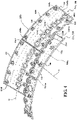
FIG. 4 , in one disclosed non-limiting embodiment, each of theforward liner panels aft liner panels perimeter rail circumferential edge circumferential edge circumferential edge perimeter rail forward liner panels aft liner panels respective support shell circumferential edge respective support shell perimeter rail circumferential edge circumferential edge forward liner panels aft liner panels respective support shell - A multiple of
studs 100 are located adjacent to the respective forward and aftcircumferential edge studs 100 may be at least partially surrounded byposts 132 to at least partially support thefastener 102 and provide a stand-off between eachforward liner panels aft liner panels respective support shell - The
dilution passages 116 are located downstream of the forwardcircumferential edge aft liner panels combustion chamber 66 by direct supply of cooling air from the respectiveannular plenums dilution passages 116 pass air at the pressure outside thecombustion chamber 66 directly into thecombustion chamber 66. - This dilution air is not primarily used for cooling of the metal surfaces of the combustor shells or panels, but to condition the combustion products within the
combustion chamber 66. In this disclosed non-limiting embodiment, thedilution passages 116 include at least one set of circumferentially alternatingmajor dilution passages 116A andminor dilution passages 116B (also shown inFIG. 6 ). That is, in some circumferentially offset locations, twomajor dilution passages 116A are separated by oneminor dilution passages 116B. Here, every twomajor dilution passages 116A are separated by oneminor dilution passages 116B but may still be considered "circumferentially alternating" as described herein. In one example, each of themajor dilution passages 116A is about 0.5" (12.7 mm) in diameter and the total number ofmajor dilution passages 116A communicates about eighty-five percent (85%) of the dilution airflow. Theminor dilution passages 116B are each about 0.2" (5.1 mm) in diameter and the total number ofminor dilution passages 116B communicates about fifteen percent (15%) of the dilution airflow. It should be appreciated that thedilution passages - With reference to
FIG. 7 , theforward liner panels circumferential edge 124a while theaft liner panels circumferential edge 122b. "Complementary," as defined herein, is that the non-linear aftcircumferential edge 124a fits together with the non-linear forwardcircumferential edge 122b to form anon-linear interface 130. Thenon-linear interface 130 may be repeated over one or a multiple of adjacent forward and aft liner panels. Further, although illustrated between a forward and aft liner panel, the non-linear interface may be located between other arrays such as between liner and bulkhead panels. - In one non-limiting embodiment, the non-linear aft
circumferential edge 124a and the non-linear forwardcircumferential edge 122b are contoured with respect to each of the multiple ofstuds 100. That is, the non-linear aftcircumferential edge 124a and the non-linear forwardcircumferential edge 122b are spaced a distance D1 from each of the multiple ofstuds 100. In one example, the distance D1 is 2.0X-10X where X is the diameter of the stud 100 (FIG. 8 ). In this example, a stud of about 0.25 inches (6.35mm) results in the respective non-linear aftcircumferential edge 124a and the non-linear forwardcircumferential edge 122b to be spaced about 0.5 - 2.5 inches (12.5 - 63.5 mm) from thestud 100. - With reference to
FIG. 9 , in one non-limiting embodiment, the non-linear aftcircumferential edge 124a and the non-linear forwardcircumferential edge 122b are contoured with respect to each of the multiple ofdilution passages 116. That is, the non-linear aftcircumferential edge 124a and the non-linear forwardcircumferential edge 122b are spaced a distance D2 from each of the multiple ofdilution passages 116. In one example, the distance D2 is 0.5X-2X where X is the diameter of the dilution passage 116 (FIG. 10 ). In this example, adilution passages 116 of about 0.5 inches (12.7 mm) results in the respective non-linear aftcircumferential edge 124a and the non-linear forwardcircumferential edge 122b to be spaced about 0.25 - 1 inches (6.25 - 25 mm) from thedilution passage 116. - With reference to
FIG. 11 , in one non-limiting embodiment, the non-linear aftcircumferential edge 124a and the non-linear forwardcircumferential edge 122b are contoured with respect to each of the multiple ofdilution passages 116 as well as each of multiple ofstuds 100 which may result in a relatively complex forward and aft liner panel interface. The curved edged profiles can be cooled more effectively by providing space between panel features and in areas subject to high heat transfer. The curved edges are also readily employed in cast and machined panel designs and incorporated in dual wall liners and facilitates packaging and repair options for refurbishment of combustors. - The non-linear forward and aft liner panel interface increases combustor durability and the ability to optimize the combustor design and performance. Combustor liners with a kink or bend can eliminate interfaces that result in steps, dead regions, cooling challenges and adverse local aerodynamics. Panels of this geometry edges are readily employed in cast and machined panel designs and incorporated in dual wall liners.
- The use of the terms "a" and "an" and "the" and similar references in the context of description (especially in the context of the following claims) are to be construed to cover both the singular and the plural, unless otherwise indicated herein or specifically contradicted by context. The modifier "about" used in connection with a quantity is inclusive of the stated value and has the meaning dictated by the context (e.g., it includes the degree of error associated with measurement of the particular quantity). All ranges disclosed herein are inclusive of the endpoints, and the endpoints are independently combinable with each other. It should be appreciated that relative positional terms such as "forward," "aft," "upper," "lower," "above," "below," and the like are with reference to the normal operational attitude of the vehicle and should not be considered otherwise limiting.
- Although the different non-limiting embodiments have specific illustrated components, the embodiments of this invention are not limited to those particular combinations. It is possible to use some of the components or features from any of the non-limiting embodiments in combination with features or components from any of the other non-limiting embodiments.
- It should be appreciated that like reference numerals identify corresponding or similar elements throughout the several drawings. It should also be appreciated that although a particular component arrangement is disclosed in the illustrated embodiment, other arrangements will benefit herefrom.
- Although particular step sequences are shown, described, and claimed, it should be understood that steps may be performed in any order, separated or combined unless otherwise indicated and will still benefit from the present invention. .
- The foregoing description is exemplary rather than defined by the limitations within. Various non-limiting embodiments are disclosed herein, however, one of ordinary skill in the art would recognize that various modifications and variations in light of the above teachings will fall within the scope of the appended claims. It is therefore to be appreciated that within the scope of the appended claims, the invention may be practiced other than as specifically described. For that reason the appended claims should be studied to determine true scope and content.
Claims (5)
- A combustor (56) for a gas turbine engine (20) comprising:a support shell (68,70);a forward liner panel (72A,72B) mounted to the support shell (68,70) via a multiple of studs (100), the forward liner panel (72A,72B) including an aft non-linear circumferential edge (124a); andan aft liner panel (74A,74B) mounted to the support shell (68,70) via a multiple of studs (100), the aft liner panel (74A,74B) including a forward non-linear circumferential edge (122b),wherein the combustor (56) comprises cavities (106) between the support shell (68,70) and each of the forward and aft liner panels (72A, 72B, 74A, 74B),wherein the support shell (68,70) comprises impingement passages (104) configured to allow cooling air to enter the cavities (106) and to provide impingement cooling of a cold side (110) of the forward and aft liner panels (72A, 72B, 74A, 74B),characterised in that:the forward non-linear circumferential edge (122b) of the aft liner panel (74A,74B) is complementary to the aft non-linear circumferential edge (124a) of the forward liner panel (72A,72B);the forward non-linear circumferential edge (122b) and the aft non-linear circumferential edge (124a) form a non-linear interface (130); andthe forward and aft liner panels (72A, 72B, 74A, 74B) each comprise effusion passages (108) configured to allow the cooling air to pass from the cavities (106) to a hot side (112) of the respective forward and aft liner panels (72A, 72B, 74A, 74B).
- The combustor (56) as recited in claim 1, wherein the forward and aft non-linear circumferential edges (122b,124a) are defined with respect to each of a multiple of studs (100).
- The combustor (56) as recited in claim 2, wherein the non-linear circumferential edges (122b,124a) are spaced a distance (D1) from each of the multiple of studs (100), and the distance (D1) is 2.0X-10X, where X is a diameter of the stud (100).
- The combustor (56) as recited in any preceding claim, wherein the forward and aft non-linear circumferential edges (122b,124a) are defined with respect to each of a multiple of dilution passages (116).
- The combustor as recited in claim 4, wherein the forward and aft non-linear circumferential edges (122b,124a) are spaced a distance (D2) from each of the multiple of dilution passages (116), and the distance (D2) is 0.5X-2X, where X is the diameter of the dilution passage (116).
Applications Claiming Priority (1)
| Application Number | Priority Date | Filing Date | Title |
|---|---|---|---|
| US15/348,639 US10655853B2 (en) | 2016-11-10 | 2016-11-10 | Combustor liner panel with non-linear circumferential edge for a gas turbine engine combustor |
Publications (2)
| Publication Number | Publication Date |
|---|---|
| EP3321588A1 EP3321588A1 (en) | 2018-05-16 |
| EP3321588B1 true EP3321588B1 (en) | 2022-04-06 |
Family
ID=60327104
Family Applications (1)
| Application Number | Title | Priority Date | Filing Date |
|---|---|---|---|
| EP17201213.0A Active EP3321588B1 (en) | 2016-11-10 | 2017-11-10 | Combustor for a gas turbine engine |
Country Status (2)
| Country | Link |
|---|---|
| US (1) | US10655853B2 (en) |
| EP (1) | EP3321588B1 (en) |
Family Cites Families (71)
| Publication number | Priority date | Publication date | Assignee | Title |
|---|---|---|---|---|
| US4236378A (en) | 1978-03-01 | 1980-12-02 | General Electric Company | Sectoral combustor for burning low-BTU fuel gas |
| US4302941A (en) | 1980-04-02 | 1981-12-01 | United Technologies Corporation | Combuster liner construction for gas turbine engine |
| US4773227A (en) * | 1982-04-07 | 1988-09-27 | United Technologies Corporation | Combustion chamber with improved liner construction |
| DE3664374D1 (en) * | 1985-12-02 | 1989-08-17 | Siemens Ag | Heat shield arrangement, especially for the structural components of a gas turbine plant |
| US5553455A (en) | 1987-12-21 | 1996-09-10 | United Technologies Corporation | Hybrid ceramic article |
| GB2267736B (en) | 1992-06-09 | 1995-08-09 | Gen Electric | Segmented turbine flowpath assembly |
| FR2752916B1 (en) | 1996-09-05 | 1998-10-02 | Snecma | THERMAL PROTECTIVE SHIRT FOR TURBOREACTOR COMBUSTION CHAMBER |
| EP1064510B1 (en) | 1998-03-19 | 2002-11-13 | Siemens Aktiengesellschaft | Wall segment for a combustion chamber and combustion chamber |
| US6101814A (en) * | 1999-04-15 | 2000-08-15 | United Technologies Corporation | Low emissions can combustor with dilution hole arrangement for a turbine engine |
| DE10114619B4 (en) | 2000-03-27 | 2006-07-27 | Cummins Inc., Columbus | Ventilating fastening element |
| US6675582B2 (en) | 2001-05-23 | 2004-01-13 | General Electric Company | Slot cooled combustor line |
| US6581285B2 (en) | 2001-06-11 | 2003-06-24 | General Electric Co. | Methods for replacing nuggeted combustor liner panels |
| US6568079B2 (en) | 2001-06-11 | 2003-05-27 | General Electric Company | Methods for replacing combustor liner panels |
| GB0117110D0 (en) | 2001-07-13 | 2001-09-05 | Siemens Ag | Coolable segment for a turbomachinery and combustion turbine |
| US6655146B2 (en) | 2001-07-31 | 2003-12-02 | General Electric Company | Hybrid film cooled combustor liner |
| FR2840974B1 (en) | 2002-06-13 | 2005-12-30 | Snecma Propulsion Solide | SEAL RING FOR COMBUSTION CAHMBERS AND COMBUSTION CHAMBER COMPRISING SUCH A RING |
| ES2307834T3 (en) | 2003-01-29 | 2008-12-01 | Siemens Aktiengesellschaft | COMBUSTION CHAMBER. |
| US6931855B2 (en) | 2003-05-12 | 2005-08-23 | Siemens Westinghouse Power Corporation | Attachment system for coupling combustor liners to a carrier of a turbine combustor |
| EP1482246A1 (en) | 2003-05-30 | 2004-12-01 | Siemens Aktiengesellschaft | Combustion chamber |
| US7363763B2 (en) | 2003-10-23 | 2008-04-29 | United Technologies Corporation | Combustor |
| US6868675B1 (en) | 2004-01-09 | 2005-03-22 | Honeywell International Inc. | Apparatus and method for controlling combustor liner carbon formation |
| EP1666797A1 (en) | 2004-12-01 | 2006-06-07 | Siemens Aktiengesellschaft | Heat shield element, method for manufacturing the same, heat shield and combustor |
| US8418470B2 (en) | 2005-10-07 | 2013-04-16 | United Technologies Corporation | Gas turbine combustor bulkhead panel |
| GB2432902B (en) | 2005-12-03 | 2011-01-12 | Alstom Technology Ltd | Gas turbine sub-assemblies |
| US7665307B2 (en) | 2005-12-22 | 2010-02-23 | United Technologies Corporation | Dual wall combustor liner |
| US20080003078A1 (en) | 2006-05-02 | 2008-01-03 | United Technologies Corporation | Fastener |
| US7524167B2 (en) | 2006-05-04 | 2009-04-28 | Siemens Energy, Inc. | Combustor spring clip seal system |
| EP1862740B1 (en) | 2006-05-31 | 2015-09-16 | Siemens Aktiengesellschaft | Combustion chamber wall |
| US7895841B2 (en) * | 2006-07-14 | 2011-03-01 | General Electric Company | Method and apparatus to facilitate reducing NOx emissions in turbine engines |
| WO2008017551A2 (en) | 2006-08-07 | 2008-02-14 | Alstom Technology Ltd | Combustion chamber of a combustion plant |
| US8141370B2 (en) | 2006-08-08 | 2012-03-27 | General Electric Company | Methods and apparatus for radially compliant component mounting |
| US7726131B2 (en) | 2006-12-19 | 2010-06-01 | Pratt & Whitney Canada Corp. | Floatwall dilution hole cooling |
| US8528339B2 (en) | 2007-04-05 | 2013-09-10 | Siemens Energy, Inc. | Stacked laminate gas turbine component |
| US8256223B2 (en) | 2007-10-16 | 2012-09-04 | United Technologies Corporation | Ceramic combustor liner panel for a gas turbine engine |
| GB0801839D0 (en) | 2008-02-01 | 2008-03-05 | Rolls Royce Plc | combustion apparatus |
| WO2009103658A1 (en) | 2008-02-20 | 2009-08-27 | Alstom Technology Ltd | Gas turbine having an annular combustion chamber |
| US8522560B2 (en) | 2009-03-25 | 2013-09-03 | United Technologies Corporation | Fuel-cooled heat exchanger with thermoelectric device compression |
| US8015817B2 (en) | 2009-06-10 | 2011-09-13 | Siemens Energy, Inc. | Cooling structure for gas turbine transition duct |
| GB0913580D0 (en) | 2009-08-05 | 2009-09-16 | Rolls Royce Plc | Combustor tile |
| US8359865B2 (en) | 2010-02-04 | 2013-01-29 | United Technologies Corporation | Combustor liner segment seal member |
| US8359866B2 (en) | 2010-02-04 | 2013-01-29 | United Technologies Corporation | Combustor liner segment seal member |
| US8608443B2 (en) * | 2010-06-11 | 2013-12-17 | Siemens Energy, Inc. | Film cooled component wall in a turbine engine |
| US9010121B2 (en) | 2010-12-10 | 2015-04-21 | Rolls-Royce Plc | Combustion chamber |
| US8720204B2 (en) | 2011-02-09 | 2014-05-13 | Siemens Energy, Inc. | Resonator system with enhanced combustor liner cooling |
| JP5696566B2 (en) | 2011-03-31 | 2015-04-08 | 株式会社Ihi | Combustor for gas turbine engine and gas turbine engine |
| US8727714B2 (en) | 2011-04-27 | 2014-05-20 | Siemens Energy, Inc. | Method of forming a multi-panel outer wall of a component for use in a gas turbine engine |
| US9534783B2 (en) | 2011-07-21 | 2017-01-03 | United Technologies Corporation | Insert adjacent to a heat shield element for a gas turbine engine combustor |
| US8745988B2 (en) | 2011-09-06 | 2014-06-10 | Pratt & Whitney Canada Corp. | Pin fin arrangement for heat shield of gas turbine engine |
| US8839627B2 (en) | 2012-01-31 | 2014-09-23 | United Technologies Corporation | Annular combustor |
| EP2679780B8 (en) | 2012-06-28 | 2016-09-14 | General Electric Technology GmbH | Diffuser for the exhaust section of a gas turbine and gas turbine with such a diffuser |
| US9482432B2 (en) | 2012-09-26 | 2016-11-01 | United Technologies Corporation | Gas turbine engine combustor with integrated combustor vane having swirler |
| US9249732B2 (en) | 2012-09-28 | 2016-02-02 | United Technologies Corporation | Panel support hanger for a turbine engine |
| US9243515B2 (en) | 2012-09-28 | 2016-01-26 | United Technologies Corporation | Support hanger for flexibly connecting a plurality of panels |
| US10107497B2 (en) | 2012-10-04 | 2018-10-23 | United Technologies Corporation | Gas turbine engine combustor liner |
| US20150362192A1 (en) | 2013-01-17 | 2015-12-17 | United Technologies Corporation | Gas turbine engine combustor liner assembly with convergent hyperbolic profile |
| US9423129B2 (en) | 2013-03-15 | 2016-08-23 | Rolls-Royce Corporation | Shell and tiled liner arrangement for a combustor |
| US10634351B2 (en) | 2013-04-12 | 2020-04-28 | United Technologies Corporation | Combustor panel T-junction cooling |
| US20160109129A1 (en) * | 2013-05-21 | 2016-04-21 | Siemens Aktiengesellschaft | Heat shield tile for a heat shield of a combustion chamber |
| US8984896B2 (en) | 2013-08-23 | 2015-03-24 | Pratt & Whitney Canada Corp. | Interlocking combustor heat shield panels |
| GB201315871D0 (en) | 2013-09-06 | 2013-10-23 | Rolls Royce Plc | A combustion chamber arrangement |
| WO2015126501A2 (en) | 2013-12-06 | 2015-08-27 | United Technologies Corporation | Co-swirl orientation of combustor effusion passages for gas turbine engine combustor |
| US9410702B2 (en) | 2014-02-10 | 2016-08-09 | Honeywell International Inc. | Gas turbine engine combustors with effusion and impingement cooling and methods for manufacturing the same using additive manufacturing techniques |
| DE102014204482A1 (en) * | 2014-03-11 | 2015-09-17 | Rolls-Royce Deutschland Ltd & Co Kg | Combustion chamber of a gas turbine |
| DE102014204476A1 (en) | 2014-03-11 | 2015-10-01 | Rolls-Royce Deutschland Ltd & Co Kg | Combustion chamber of a gas turbine |
| DE102014204481A1 (en) | 2014-03-11 | 2015-09-17 | Rolls-Royce Deutschland Ltd & Co Kg | Combustion chamber of a gas turbine |
| US9557060B2 (en) | 2014-06-16 | 2017-01-31 | Pratt & Whitney Canada Corp. | Combustor heat shield |
| US10941942B2 (en) | 2014-12-31 | 2021-03-09 | Rolls-Royce North American Technologies Inc. | Retention system for gas turbine engine assemblies |
| GB201501817D0 (en) | 2015-02-04 | 2015-03-18 | Rolls Royce Plc | A combustion chamber and a combustion chamber segment |
| DE102015205975A1 (en) | 2015-04-02 | 2016-10-06 | Siemens Aktiengesellschaft | Umführungs heat shield element |
| GB201603166D0 (en) | 2016-02-24 | 2016-04-06 | Rolls Royce Plc | A combustion chamber |
| US10684014B2 (en) | 2016-08-04 | 2020-06-16 | Raytheon Technologies Corporation | Combustor panel for gas turbine engine |
-
2016
- 2016-11-10 US US15/348,639 patent/US10655853B2/en active Active
-
2017
- 2017-11-10 EP EP17201213.0A patent/EP3321588B1/en active Active
Non-Patent Citations (1)
| Title |
|---|
| None * |
Also Published As
| Publication number | Publication date |
|---|---|
| US20180231250A1 (en) | 2018-08-16 |
| EP3321588A1 (en) | 2018-05-16 |
| US10655853B2 (en) | 2020-05-19 |
Similar Documents
| Publication | Publication Date | Title |
|---|---|---|
| EP3366995B1 (en) | Combustor liner panel assembly and method for cooling the same | |
| EP3366996B1 (en) | Combustor liner panel end rails forming an angled cooling interface passage for a gas turbine engine combustor | |
| EP3366998B1 (en) | Combustor comprising liner panels end rails with curved interface passage for a gas turbine engine | |
| EP3415819B1 (en) | Combustor for a gas turbine engine comprising liner panels with a diffused interface passage | |
| EP3366997B1 (en) | Combustor liner panel end rail cooling enhancement features for a gas turbine engine combustor | |
| EP3361158B1 (en) | Combustor for a gas turbine engine | |
| EP3330611B1 (en) | Regulated combustor liner panel for a gas turbine engine combustor | |
| EP3321587B1 (en) | Axial non-linear interface for combustor liner panels in a gas turbine combustor | |
| EP3321585B1 (en) | Non-planar combustor liner panel for a gas turbine engine combustor | |
| EP3321584A1 (en) | Axially non-planar combustor liner panel for a gas turbine engine combustor | |
| EP3084307B1 (en) | Dilution passage arrangement for gas turbine engine combustor | |
| EP3321588B1 (en) | Combustor for a gas turbine engine | |
| EP3318803B1 (en) | Stud arrangement for gas turbine engine combustor | |
| EP3315862B1 (en) | Cast combustor liner panel with a radius edge for gas turbine engine combustor |
Legal Events
| Date | Code | Title | Description |
|---|---|---|---|
| PUAI | Public reference made under article 153(3) epc to a published international application that has entered the european phase |
Free format text: ORIGINAL CODE: 0009012 |
|
| STAA | Information on the status of an ep patent application or granted ep patent |
Free format text: STATUS: THE APPLICATION HAS BEEN PUBLISHED |
|
| AK | Designated contracting states |
Kind code of ref document: A1 Designated state(s): AL AT BE BG CH CY CZ DE DK EE ES FI FR GB GR HR HU IE IS IT LI LT LU LV MC MK MT NL NO PL PT RO RS SE SI SK SM TR |
|
| AX | Request for extension of the european patent |
Extension state: BA ME |
|
| STAA | Information on the status of an ep patent application or granted ep patent |
Free format text: STATUS: REQUEST FOR EXAMINATION WAS MADE |
|
| 17P | Request for examination filed |
Effective date: 20181115 |
|
| RBV | Designated contracting states (corrected) |
Designated state(s): AL AT BE BG CH CY CZ DE DK EE ES FI FR GB GR HR HU IE IS IT LI LT LU LV MC MK MT NL NO PL PT RO RS SE SI SK SM TR |
|
| STAA | Information on the status of an ep patent application or granted ep patent |
Free format text: STATUS: EXAMINATION IS IN PROGRESS |
|
| 17Q | First examination report despatched |
Effective date: 20200421 |
|
| RAP1 | Party data changed (applicant data changed or rights of an application transferred) |
Owner name: RAYTHEON TECHNOLOGIES CORPORATION |
|
| GRAP | Despatch of communication of intention to grant a patent |
Free format text: ORIGINAL CODE: EPIDOSNIGR1 |
|
| STAA | Information on the status of an ep patent application or granted ep patent |
Free format text: STATUS: GRANT OF PATENT IS INTENDED |
|
| INTG | Intention to grant announced |
Effective date: 20211020 |
|
| GRAS | Grant fee paid |
Free format text: ORIGINAL CODE: EPIDOSNIGR3 |
|
| GRAA | (expected) grant |
Free format text: ORIGINAL CODE: 0009210 |
|
| STAA | Information on the status of an ep patent application or granted ep patent |
Free format text: STATUS: THE PATENT HAS BEEN GRANTED |
|
| AK | Designated contracting states |
Kind code of ref document: B1 Designated state(s): AL AT BE BG CH CY CZ DE DK EE ES FI FR GB GR HR HU IE IS IT LI LT LU LV MC MK MT NL NO PL PT RO RS SE SI SK SM TR |
|
| REG | Reference to a national code |
Ref country code: GB Ref legal event code: FG4D |
|
| REG | Reference to a national code |
Ref country code: CH Ref legal event code: EP |
|
| REG | Reference to a national code |
Ref country code: AT Ref legal event code: REF Ref document number: 1481671 Country of ref document: AT Kind code of ref document: T Effective date: 20220415 |
|
| REG | Reference to a national code |
Ref country code: DE Ref legal event code: R096 Ref document number: 602017055472 Country of ref document: DE |
|
| REG | Reference to a national code |
Ref country code: IE Ref legal event code: FG4D |
|
| REG | Reference to a national code |
Ref country code: LT Ref legal event code: MG9D |
|
| REG | Reference to a national code |
Ref country code: NL Ref legal event code: MP Effective date: 20220406 |
|
| REG | Reference to a national code |
Ref country code: AT Ref legal event code: MK05 Ref document number: 1481671 Country of ref document: AT Kind code of ref document: T Effective date: 20220406 |
|
| PG25 | Lapsed in a contracting state [announced via postgrant information from national office to epo] |
Ref country code: NL Free format text: LAPSE BECAUSE OF FAILURE TO SUBMIT A TRANSLATION OF THE DESCRIPTION OR TO PAY THE FEE WITHIN THE PRESCRIBED TIME-LIMIT Effective date: 20220406 |
|
| PG25 | Lapsed in a contracting state [announced via postgrant information from national office to epo] |
Ref country code: SE Free format text: LAPSE BECAUSE OF FAILURE TO SUBMIT A TRANSLATION OF THE DESCRIPTION OR TO PAY THE FEE WITHIN THE PRESCRIBED TIME-LIMIT Effective date: 20220406 Ref country code: PT Free format text: LAPSE BECAUSE OF FAILURE TO SUBMIT A TRANSLATION OF THE DESCRIPTION OR TO PAY THE FEE WITHIN THE PRESCRIBED TIME-LIMIT Effective date: 20220808 Ref country code: NO Free format text: LAPSE BECAUSE OF FAILURE TO SUBMIT A TRANSLATION OF THE DESCRIPTION OR TO PAY THE FEE WITHIN THE PRESCRIBED TIME-LIMIT Effective date: 20220706 Ref country code: LT Free format text: LAPSE BECAUSE OF FAILURE TO SUBMIT A TRANSLATION OF THE DESCRIPTION OR TO PAY THE FEE WITHIN THE PRESCRIBED TIME-LIMIT Effective date: 20220406 Ref country code: HR Free format text: LAPSE BECAUSE OF FAILURE TO SUBMIT A TRANSLATION OF THE DESCRIPTION OR TO PAY THE FEE WITHIN THE PRESCRIBED TIME-LIMIT Effective date: 20220406 Ref country code: GR Free format text: LAPSE BECAUSE OF FAILURE TO SUBMIT A TRANSLATION OF THE DESCRIPTION OR TO PAY THE FEE WITHIN THE PRESCRIBED TIME-LIMIT Effective date: 20220707 Ref country code: FI Free format text: LAPSE BECAUSE OF FAILURE TO SUBMIT A TRANSLATION OF THE DESCRIPTION OR TO PAY THE FEE WITHIN THE PRESCRIBED TIME-LIMIT Effective date: 20220406 Ref country code: ES Free format text: LAPSE BECAUSE OF FAILURE TO SUBMIT A TRANSLATION OF THE DESCRIPTION OR TO PAY THE FEE WITHIN THE PRESCRIBED TIME-LIMIT Effective date: 20220406 Ref country code: BG Free format text: LAPSE BECAUSE OF FAILURE TO SUBMIT A TRANSLATION OF THE DESCRIPTION OR TO PAY THE FEE WITHIN THE PRESCRIBED TIME-LIMIT Effective date: 20220706 Ref country code: AT Free format text: LAPSE BECAUSE OF FAILURE TO SUBMIT A TRANSLATION OF THE DESCRIPTION OR TO PAY THE FEE WITHIN THE PRESCRIBED TIME-LIMIT Effective date: 20220406 |
|
| PG25 | Lapsed in a contracting state [announced via postgrant information from national office to epo] |
Ref country code: RS Free format text: LAPSE BECAUSE OF FAILURE TO SUBMIT A TRANSLATION OF THE DESCRIPTION OR TO PAY THE FEE WITHIN THE PRESCRIBED TIME-LIMIT Effective date: 20220406 Ref country code: PL Free format text: LAPSE BECAUSE OF FAILURE TO SUBMIT A TRANSLATION OF THE DESCRIPTION OR TO PAY THE FEE WITHIN THE PRESCRIBED TIME-LIMIT Effective date: 20220406 Ref country code: LV Free format text: LAPSE BECAUSE OF FAILURE TO SUBMIT A TRANSLATION OF THE DESCRIPTION OR TO PAY THE FEE WITHIN THE PRESCRIBED TIME-LIMIT Effective date: 20220406 Ref country code: IS Free format text: LAPSE BECAUSE OF FAILURE TO SUBMIT A TRANSLATION OF THE DESCRIPTION OR TO PAY THE FEE WITHIN THE PRESCRIBED TIME-LIMIT Effective date: 20220806 |
|
| REG | Reference to a national code |
Ref country code: DE Ref legal event code: R097 Ref document number: 602017055472 Country of ref document: DE |
|
| PG25 | Lapsed in a contracting state [announced via postgrant information from national office to epo] |
Ref country code: SM Free format text: LAPSE BECAUSE OF FAILURE TO SUBMIT A TRANSLATION OF THE DESCRIPTION OR TO PAY THE FEE WITHIN THE PRESCRIBED TIME-LIMIT Effective date: 20220406 Ref country code: SK Free format text: LAPSE BECAUSE OF FAILURE TO SUBMIT A TRANSLATION OF THE DESCRIPTION OR TO PAY THE FEE WITHIN THE PRESCRIBED TIME-LIMIT Effective date: 20220406 Ref country code: RO Free format text: LAPSE BECAUSE OF FAILURE TO SUBMIT A TRANSLATION OF THE DESCRIPTION OR TO PAY THE FEE WITHIN THE PRESCRIBED TIME-LIMIT Effective date: 20220406 Ref country code: EE Free format text: LAPSE BECAUSE OF FAILURE TO SUBMIT A TRANSLATION OF THE DESCRIPTION OR TO PAY THE FEE WITHIN THE PRESCRIBED TIME-LIMIT Effective date: 20220406 Ref country code: DK Free format text: LAPSE BECAUSE OF FAILURE TO SUBMIT A TRANSLATION OF THE DESCRIPTION OR TO PAY THE FEE WITHIN THE PRESCRIBED TIME-LIMIT Effective date: 20220406 Ref country code: CZ Free format text: LAPSE BECAUSE OF FAILURE TO SUBMIT A TRANSLATION OF THE DESCRIPTION OR TO PAY THE FEE WITHIN THE PRESCRIBED TIME-LIMIT Effective date: 20220406 |
|
| PLBE | No opposition filed within time limit |
Free format text: ORIGINAL CODE: 0009261 |
|
| STAA | Information on the status of an ep patent application or granted ep patent |
Free format text: STATUS: NO OPPOSITION FILED WITHIN TIME LIMIT |
|
| 26N | No opposition filed |
Effective date: 20230110 |
|
| PG25 | Lapsed in a contracting state [announced via postgrant information from national office to epo] |
Ref country code: AL Free format text: LAPSE BECAUSE OF FAILURE TO SUBMIT A TRANSLATION OF THE DESCRIPTION OR TO PAY THE FEE WITHIN THE PRESCRIBED TIME-LIMIT Effective date: 20220406 |
|
| PG25 | Lapsed in a contracting state [announced via postgrant information from national office to epo] |
Ref country code: SI Free format text: LAPSE BECAUSE OF FAILURE TO SUBMIT A TRANSLATION OF THE DESCRIPTION OR TO PAY THE FEE WITHIN THE PRESCRIBED TIME-LIMIT Effective date: 20220406 |
|
| P01 | Opt-out of the competence of the unified patent court (upc) registered |
Effective date: 20230520 |
|
| PG25 | Lapsed in a contracting state [announced via postgrant information from national office to epo] |
Ref country code: MC Free format text: LAPSE BECAUSE OF FAILURE TO SUBMIT A TRANSLATION OF THE DESCRIPTION OR TO PAY THE FEE WITHIN THE PRESCRIBED TIME-LIMIT Effective date: 20220406 |
|
| REG | Reference to a national code |
Ref country code: CH Ref legal event code: PL |
|
| REG | Reference to a national code |
Ref country code: BE Ref legal event code: MM Effective date: 20221130 |
|
| PG25 | Lapsed in a contracting state [announced via postgrant information from national office to epo] |
Ref country code: LI Free format text: LAPSE BECAUSE OF NON-PAYMENT OF DUE FEES Effective date: 20221130 Ref country code: CH Free format text: LAPSE BECAUSE OF NON-PAYMENT OF DUE FEES Effective date: 20221130 |
|
| PG25 | Lapsed in a contracting state [announced via postgrant information from national office to epo] |
Ref country code: LU Free format text: LAPSE BECAUSE OF NON-PAYMENT OF DUE FEES Effective date: 20221110 |
|
| PG25 | Lapsed in a contracting state [announced via postgrant information from national office to epo] |
Ref country code: IE Free format text: LAPSE BECAUSE OF NON-PAYMENT OF DUE FEES Effective date: 20221110 |
|
| PG25 | Lapsed in a contracting state [announced via postgrant information from national office to epo] |
Ref country code: BE Free format text: LAPSE BECAUSE OF NON-PAYMENT OF DUE FEES Effective date: 20221130 |
|
| PGFP | Annual fee paid to national office [announced via postgrant information from national office to epo] |
Ref country code: GB Payment date: 20231019 Year of fee payment: 7 |
|
| PG25 | Lapsed in a contracting state [announced via postgrant information from national office to epo] |
Ref country code: IT Free format text: LAPSE BECAUSE OF FAILURE TO SUBMIT A TRANSLATION OF THE DESCRIPTION OR TO PAY THE FEE WITHIN THE PRESCRIBED TIME-LIMIT Effective date: 20220406 |
|
| PGFP | Annual fee paid to national office [announced via postgrant information from national office to epo] |
Ref country code: FR Payment date: 20231019 Year of fee payment: 7 Ref country code: DE Payment date: 20231019 Year of fee payment: 7 |
|
| PG25 | Lapsed in a contracting state [announced via postgrant information from national office to epo] |
Ref country code: HU Free format text: LAPSE BECAUSE OF FAILURE TO SUBMIT A TRANSLATION OF THE DESCRIPTION OR TO PAY THE FEE WITHIN THE PRESCRIBED TIME-LIMIT; INVALID AB INITIO Effective date: 20171110 |