EP2508467A1 - Appareil de levage et de manutention - Google Patents
Appareil de levage et de manutention Download PDFInfo
- Publication number
- EP2508467A1 EP2508467A1 EP11290171A EP11290171A EP2508467A1 EP 2508467 A1 EP2508467 A1 EP 2508467A1 EP 11290171 A EP11290171 A EP 11290171A EP 11290171 A EP11290171 A EP 11290171A EP 2508467 A1 EP2508467 A1 EP 2508467A1
- Authority
- EP
- European Patent Office
- Prior art keywords
- plates
- mast
- orifices
- desk
- pivoting arms
- Prior art date
- Legal status (The legal status is an assumption and is not a legal conclusion. Google has not performed a legal analysis and makes no representation as to the accuracy of the status listed.)
- Granted
Links
- 230000009193 crawling Effects 0.000 claims abstract description 5
- 238000013519 translation Methods 0.000 claims description 6
- 238000003780 insertion Methods 0.000 claims description 5
- 230000037431 insertion Effects 0.000 claims description 5
- 230000003247 decreasing effect Effects 0.000 claims description 2
- 230000035515 penetration Effects 0.000 claims 1
- 238000009434 installation Methods 0.000 abstract 1
- 238000013459 approach Methods 0.000 description 2
- 239000000463 material Substances 0.000 description 2
- 238000010276 construction Methods 0.000 description 1
- 238000013461 design Methods 0.000 description 1
- 238000012423 maintenance Methods 0.000 description 1
- 239000011505 plaster Substances 0.000 description 1
- 239000002023 wood Substances 0.000 description 1
Images


Classifications
-
- B—PERFORMING OPERATIONS; TRANSPORTING
- B66—HOISTING; LIFTING; HAULING
- B66F—HOISTING, LIFTING, HAULING OR PUSHING, NOT OTHERWISE PROVIDED FOR, e.g. DEVICES WHICH APPLY A LIFTING OR PUSHING FORCE DIRECTLY TO THE SURFACE OF A LOAD
- B66F19/00—Hoisting, lifting, hauling or pushing, not otherwise provided for
-
- E—FIXED CONSTRUCTIONS
- E04—BUILDING
- E04F—FINISHING WORK ON BUILDINGS, e.g. STAIRS, FLOORS
- E04F21/00—Implements for finishing work on buildings
- E04F21/18—Implements for finishing work on buildings for setting wall or ceiling slabs or plates
- E04F21/1805—Ceiling panel lifting devices
- E04F21/1811—Ceiling panel lifting devices with hand-driven crank systems, e.g. rope, cable or chain winding or rack-and-pinion mechanisms
-
- E—FIXED CONSTRUCTIONS
- E04—BUILDING
- E04F—FINISHING WORK ON BUILDINGS, e.g. STAIRS, FLOORS
- E04F21/00—Implements for finishing work on buildings
- E04F21/18—Implements for finishing work on buildings for setting wall or ceiling slabs or plates
- E04F21/1805—Ceiling panel lifting devices
- E04F21/1822—Ceiling panel lifting devices with pivotally mounted arms
-
- E—FIXED CONSTRUCTIONS
- E04—BUILDING
- E04F—FINISHING WORK ON BUILDINGS, e.g. STAIRS, FLOORS
- E04F21/00—Implements for finishing work on buildings
- E04F21/18—Implements for finishing work on buildings for setting wall or ceiling slabs or plates
- E04F21/1838—Implements for finishing work on buildings for setting wall or ceiling slabs or plates for setting a plurality of similar elements
-
- E—FIXED CONSTRUCTIONS
- E04—BUILDING
- E04F—FINISHING WORK ON BUILDINGS, e.g. STAIRS, FLOORS
- E04F21/00—Implements for finishing work on buildings
- E04F21/20—Implements for finishing work on buildings for laying flooring
- E04F21/22—Implements for finishing work on buildings for laying flooring of single elements, e.g. flooring cramps ; flexible webs
Definitions
- the present invention relates to an apparatus for lifting and handling panels made of wood, plaster or other materials, with a view to enabling a single worker to hoist the plate into its final position in order to fix it to the horizontal or inclined ceilings of a construction.
- the object of the present invention is to eliminate certain disadvantages in the form of improvements made to existing apparatus so as to facilitate their implementation, handling, operational efficiency and transport to the workplace.
- the hoist consists of a telescopic mast, the deployment of which is achieved by means of a rope hoisting system and winch-activated webbing, a folding base and an articulated adjustable plate supporting the plates .
- This mast can be inserted in the base along several orientations to improve the ergonomics of the different work positions and to optimize stability quickly and easily.
- the central tube of the desk can move to lower the plate to the ground when laying on sloping ceilings called "crawling" in the attic.
- the lifting apparatus (A) is composed of an articulated base (B) in which the telescopic mast (M) is inserted non-permanently.
- the console (P) is embedded on the telescopic mast (M), which can take several positions.
- the articulated base (B) has two housings (1, 2) forming a cross, which can receive the telescopic mast (M) and which allow two orientations of the latter and the articulated base (B) different from 90 ° and therefore different angular positions of the desk (P) relative to the articulated base (B), which facilitates the handling ergonomics and optimizes the stability of the product in different cases of laying plates (ceilings, small plates, crawling).
- the articulated base (B) is composed of a fixed foot (4) and two pivoting feet (5, 5 ') with respect to the plate (6) along the axis defined by the bolts (7) (7' ).
- Each of the two pivoting feet (5, 5 ') is provided with a spring latch (8, 8') which engages in the orifices (3a, 3b, 3c, 3d, 3a ', 3b', 3c ' , 3d ') of the plate (6) so as to immobilize the pivoting feet (5, 5') in each of these four positions defined by these orifices (3a, 3b, 3c, 3d, 3a ', 3b', 3c ' , 3d ') of the plate (6).
- the desk (P) is composed of pivoting arms (9, 9 ').
- the rotation of its pivoting arms (9, 9 ') is effected by means of the plates (11, 11') welded to the arm supports (10, 10 ') and the counter plates (12, 12') connected to the arms pivoting (9, 9 ') via the rotation about the axes defined by the bolts (13, 13').
- the translation of the pivoting arms (9, 9 ') is achieved by their slider shape in which the counter plates (12, 12') slide.
- the immobilization of these pivoting arms is performed by spring latches (14, 14 ') connected to the counter plates (12, 12').
- the spring latches (14, 14 ') are positioned in the orifices (15b, 15b') of the pivoting arms (9, 9 ') thus allowing the desk (P) to support the standard width plates of 1.2 m .
- the console (P) allows the translation of the main tube (16) relative to the central frame (17) via two yokes (19, 19 ') integral with the central frame (17); two screw handles (18, 18 ') make it possible to tighten or loosen the clevises (19, 19'), freeing or not the translation of the main tube (16).
- the console (P) can take different configurations depending on the position of the main tube (16) relative to the central frame (17).
- the main tube (16) lowered in translation relative to the central frame (17) allows the desk (P) to go down to the ground to put the plates in a roof whose inclined ceiling starts at ground level.
- the hoisting rope system is designed for each mast in the same manner as that described between the masts (20, 21).
- This pulley (22) has two sheaves (22a, 22b) of different depths that allow to have a cable (23) in tension and a cable (23 ') expanded, which serves as security cable.
- This design makes the system economical and simple in assembly and maintenance.
Landscapes
- Engineering & Computer Science (AREA)
- Architecture (AREA)
- Structural Engineering (AREA)
- Civil Engineering (AREA)
- Life Sciences & Earth Sciences (AREA)
- Geology (AREA)
- Mechanical Engineering (AREA)
- Conveying And Assembling Of Building Elements In Situ (AREA)
- Forklifts And Lifting Vehicles (AREA)
- Jib Cranes (AREA)
Abstract
Description
- La présente invention concerne un appareil de levage et de manutention de panneaux en matériaux bois, plâtre ou autre, en vue de permettre à un seul ouvrier de hisser la plaque dans sa position définitive pour procéder à sa fixation aux plafonds horizontaux ou inclinés d'une construction.
- L'état connu de la technique propose ce type de matériel objet de plusieurs brevets dont ceux du demandeur
FR 82 21785 FR 01 13237 EP1 302 607 A1 - La présente invention a pour but de supprimer certains inconvénients sous la forme d'améliorations apportées aux appareils existants de façon à faciliter leur mise en oeuvre, leur manipulation, leur efficacité opérationnelle et leur transport sur les lieux de travail.
- L'appareil de levage est composé d'un mât télescopique dont le déploiement est obtenu au moyen d'un système de mouflage de câbles et de sangle activée par un treuil, d'une base pliante et d'un pupitre réglable articulé supportant les plaques. Ce mât peut s'insérer dans la base suivant plusieurs orientations permettant d'améliorer l'ergonomie des différentes positions de travail et d'optimiser la stabilité de façon rapide et facile.
- L'ajout d'une articulation combinée à un coulissement permet de supporter efficacement des plaques de différentes dimensions et particulièrement les petites (30 à 50 cm) et ce dans des endroits les plus difficiles ou près des murs. Cette disposition permet aussi de rendre le pupitre très compact une fois replié pour faciliter son stockage et son transport.
- Le tube central du pupitre peut se déplacer pour faire descendre la plaque au ras du sol lors de la pose sur des plafonds inclinés dits "rampants" dans des combles.
- Enfin, le système de poulie est conçu à l'aide d'une double poulie particulière pour permettre d'obtenir un ensemble de deux câbles dont un tendu dit de travail et l'autre détendu dit de sécurité, pour ainsi éviter la chute du pupitre sur l'utilisateur en cas de rupture du premier câble de travail.
- La
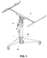
figure 1 représente l'appareil de levage en position d'utilisation, mât déployé et positionné dans le logement (2). - La
figure 2 représente l'appareil de levage pieds ouverts, en position d'utilisation, mât replié en position d'insertion. - La
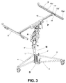
figure 3 représente l'appareil de levage en position d'utilisation, mât replié, positionné dans le logement (1). - La
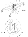
figure 4 représente la base articulée en position passage de porte. - La
figure 5 représente, en agrandissement, le système de verrouillage des pieds pivotants de la base articulée. - La
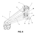
figure 6 représente la base articulée avec les pieds en position fermée - La
figure 7 représente, en perspective, l'appareil de levage en position passage de porte, pieds pivotants resserrés au maximum et pupitre incliné. - La
figure 8 représente, en perspective, l'appareil de levage, pupitre positionné pour recevoir des petites plaques et pieds en position approche de mur. - La
figure 9 représente un bras de pupitre, en position de pliage, ouvert. - La
figure 10 représente un agrandissement du système de verrouillage et d'articulation du bras. - La
figure 11 représente le support de bras du pupitre avec son système d'articulation et son verrou. - La
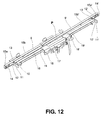
figure 12 représente le pupitre en position repliée pour le transport. - La
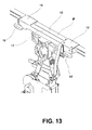
figure 13 représente en perspective le système de réglage du tube coulissant permettant de descendre le pupitre au niveau du sol. - La
figure 14 représente une vue de côté de l'appareil de levage avec pupitre en position rampant et centré. - La
figure 15 représente, en vue de côté, l'appareil de levage avec pupitre en position descendue au niveau du sol. - La
figure 16 représente, en coupe longitudinale, le mât montrant le système de mouflage. - La
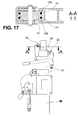
figure 17 représente une vue de face de la partie haute du mât avec sa coupe suivant AA montrant la poulie double avec ses deux réas de profondeurs différentes. - Selon les
figures 1 ,2 ,3 , l'appareil de levage (A) est composé d'une base articulée (B) dans laquelle vient s'insérer le mât télescopique (M) de façon non permanente. Le pupitre (P) vient s'encastrer sur le mât télescopique (M), pouvant prendre plusieurs positions. La base articulée (B) possède deux logements (1, 2) formant une croix, qui peuvent recevoir le mât télescopique (M) et qui permettent deux orientations de celui-ci et de la base articulée (B) différentes de 90° et donc des positions angulaires différentes du pupitre (P) par rapport à la base articulée (B), ce qui facilite l'ergonomie de manipulation et optimise la stabilité du produit dans différents cas de pose de plaques (plafonds, petites plaques, rampants). - Selon les
figures 2 ,4 ,5 et6 , la base articulée (B) est composée d'un pied fixe (4) et de deux pieds pivotants (5, 5') par rapport à la platine (6) suivant l'axe défini par les boulons (7) (7'). Chacun des deux pieds pivotants (5, 5') est pourvu d'un verrou à ressort (8, 8') qui vient s'engager dans les orifices (3a, 3b, 3c, 3d, 3a', 3b', 3c', 3d') de la platine (6) de façon à immobiliser les pieds pivotants (5, 5') dans chacune de ces quatre positions définies par ces orifices (3a, 3b, 3c, 3d, 3a', 3b', 3c', 3d') de la platine (6). - Selon les
figures 4, 5 et6 , lorsque les verrous à ressort (8, 8') sont engagés dans les orifices (3a, 3a') l'appareil est en position repliée pour son transport. - Selon les
figures 2 ,3 et4 , lorsque les verrous à ressort (8, 8') sont engagés dans les orifices (3c, 3c'), les pieds pivotants (5, 5') sont écartés au maximum conférant une bonne stabilité pour l'appareil de levage (A). - Selon les
figures 4, 5 et7 , lorsque les verrous à ressort (8, 8') sont engagés dans les orifices (3d, 3d'), les deux pieds pivotants (5, 5') sont moins écartés de façon à permettre le passage de l'appareil dans les portes sans démontage du pupitre (P). - Selon les
figures 4 et8 , lorsque les verrous à ressort (8, 8') sont engagés dans l'orifice (3b, 3b'), les deux pieds pivotants (5, 5') forment un angle de 150° permettant d'approcher l'appareil de levage (A) au plus près des murs facilitant ainsi la pose de plaques de petites largeurs aux plafonds, le long des murs. - Selon les
figures 3 ,9 ,10 ,11 et12 , le pupitre (P) est composé de bras pivotants (9, 9'). La rotation de ses bras pivotants (9, 9') est réalisée par l'intermédiaire des platines (11, 11') soudées aux supports de bras (10, 10') et les contre platines (12, 12') liées aux bras pivotants (9, 9') via la rotation autour des axes définis par les boulons (13, 13'). La translation des bras pivotants (9, 9') est réalisée par leur forme en glissière dans laquelle les contre platines (12, 12') glissent. L'immobilisation de ces bras pivotants est réalisée par des verrous à ressort (14, 14') liés aux contre platines (12, 12'). Ces verrous à ressort (14, 14') pénètrent dans les orifices (15a, 15b, 15c, 15a', 15b', 15c') réalisés sur les bras pivotants (9, 9') offrant trois positions possibles par rapport au pupitre (P). - Selon les
figures 3 ,8 ,9 et 10 , lorsque les verrous à ressort (14, 14') sont positionnés dans les orifices (15c, 15c') des bras pivotants (9, 9') du pupitre (P), ce dernier peut supporter des petites plaques de plâtre de 30 à 50 cm de large en les appuyant sur le tube principal (16). - Selon les
figures 3 ,9 et 10 , les verrous à ressort (14, 14') sont positionnés dans les orifices (15b, 15b') des bras pivotants (9, 9') permettant ainsi au pupitre (P) de supporter les plaques de largeur standard de 1, 2 m. - Selon les
figures 3 ,9 10 et12 , la position des verrous à ressort (14, 14') dans les orifices (15a, 15a') combinée avec la rotation des bras pivotants (9, 9') réalisée par les articulations composées des platines (11, 11') et des contre platines (12, 12') permettent de replier de façon compacte les bras pivotants (9, 9') en diminuant la longueur du pupitre (P). - Selon les
figures 12 et13 , le pupitre (P) permet la translation du tube principal (16) par rapport au châssis central (17) via deux chapes (19, 19') solidaires du châssis central (17) ; deux poignées à vis (18, 18') permettent de serrer ou desserrer les chapes (19, 19') libérant ou non la translation du tube principal (16). - Selon les
figures 13 ,14 et 15 , le pupitre (P) peut prendre différentes configurations suivant la position du tube principal (16) par rapport au châssis central (17). Ainsi le tube principal (16) descendu en translation par rapport au châssis central (17) permet au pupitre (P) de descendre jusqu'au sol pour poser les plaques dans un comble dont le plafond incliné démarre au niveau du sol. - Selon les
figures 16 et17 , le système de câbles de levage est conçu pour chaque mât de manière identique à celui décrit entre les mâts (20, 21). Deux câbles (23, 23') de longueur identique, fixés à une de leur extrémité dans la partie basse du mât (20) par un axe (24) et à leur autre extrémité au mât (21) par un axe (25), passent autour de la poulie (22). Cette poulie (22) a deux réas (22a, 22b) de profondeurs différentes qui permettent d'avoir un câble (23) en tension et un câble (23') détendu, qui sert de câble de sécurité. Cette conception rend le système économique et simple en montage et en maintenance.
Claims (4)
- Appareil de levage (A) composé d'une base articulée (B) comprenant un pied fixe (4) et deux pieds pivotants (5, 5') d'un mât télescopique (M) comprenant plusieurs mâts dont des mâts (20, 21) et d'un pupitre (P) comprenant un châssis central (17), un tube principal (16) et deux bras pivotants (9, 9') incluant une forme en glissière, caractérisé en ce que la base articulée (B) possède deux logements (1, 2) formant une croix, pouvant recevoir le mât télescopique (M) permettant deux orientations angulaires différentes de 90°, du mât télescopique (M) par rapport à la base articulée (B) entraînant des ergonomies différentes en fonction des cas d'utilisation (passage de portes, pose de petites plaques, pose standard, pose en rampant), tout en conservant pour chaque cas une stabilité optimisée.
- Appareil de levage (A) selon revendication 1, caractérisé en ce que par translation des contre platines (12, 12') dans la forme en glissière des bras pivotants (9) (9') et par la pénétration de verrous à ressort (14, 14') dans des orifices (15a, 15b, 15c, 15a', 15b', 15c') réalisés sur les bras pivotants (9, 9'), l'appareil de levage (A) offre trois positions possibles par rapport au pupitre (P) permettant ainsi de supporter des plaques de différentes largeurs et notamment de petites largeur, par insertion des verrous à ressort (14, 14') dans les orifices (15c, 15c'), des plaques de largeur standard par insertion des verrous à ressort (14, 14') dans les orifices (15b, 15b') et de replier les bras pivotants (9, 9') diminuant ainsi la longueur du pupitre (P) le rendant plus compact pour le transport et le rangement, par l'action combinée de l'insertion des verrous à ressort (14, 14') dans les orifices (15a, 15a') et de la rotation des bras pivotants réalisés par les articulations composées de platines (11, 11') soudées aux supports de bras (10, 10') et des contre platines (12, 12').
- Appareil de levage (A) selon revendications 1 et 2, caractérisé en ce qu'un moyen de serrage composé ici de deux poignées à vis (18, 18') serrent ou desserrent deux chapes (19, 19') solidaires du châssis central (17) libérant ainsi la translation du tube principal (16) par rapport au châssis central (17) permettant d'obtenir différentes positions du pupitre (P) et de réaliser des rampants à partit du sol puis à différentes hauteurs.
- Appareil de levage (A) selon revendication 1, caractérisé en ce que le système de câbles de levage est composé pour chaque mât de manière identique à celui décrit entre les mâts (20,21), de deux câbles (23, 23') de longueur identique, fixés à une de leur extrémité dans la partie basse du mât (20) et à leur autre extrémité au mât (21) et passant autour d'une poulie (22) dont deux réas (22a, 22b) de profondeurs différentes, permettent d'avoir le câble (23) en tension et le câble (23') détendu servant de câble de sécurité.
Priority Applications (3)
| Application Number | Priority Date | Filing Date | Title |
|---|---|---|---|
| EP20110290171 EP2508467B1 (fr) | 2011-04-04 | 2011-04-04 | Appareil de levage et de manutention |
| PT11290171T PT2508467E (pt) | 2011-04-04 | 2011-04-04 | Dispositivo de elevação e de fixação |
| ES11290171T ES2404407T3 (es) | 2011-04-04 | 2011-04-04 | Aparato de elevación y manipulación |
Applications Claiming Priority (1)
| Application Number | Priority Date | Filing Date | Title |
|---|---|---|---|
| EP20110290171 EP2508467B1 (fr) | 2011-04-04 | 2011-04-04 | Appareil de levage et de manutention |
Publications (2)
| Publication Number | Publication Date |
|---|---|
| EP2508467A1 true EP2508467A1 (fr) | 2012-10-10 |
| EP2508467B1 EP2508467B1 (fr) | 2013-03-27 |
Family
ID=44475016
Family Applications (1)
| Application Number | Title | Priority Date | Filing Date |
|---|---|---|---|
| EP20110290171 Active EP2508467B1 (fr) | 2011-04-04 | 2011-04-04 | Appareil de levage et de manutention |
Country Status (3)
| Country | Link |
|---|---|
| EP (1) | EP2508467B1 (fr) |
| ES (1) | ES2404407T3 (fr) |
| PT (1) | PT2508467E (fr) |
Cited By (5)
| Publication number | Priority date | Publication date | Assignee | Title |
|---|---|---|---|---|
| WO2016071591A1 (fr) * | 2014-11-06 | 2016-05-12 | Établissements Pierre Gréhal Et Cie Sa | Piètement roulant pour un mât télescopique d'un appareil de levage de plaques, appareil muni d'un tel piètement, et procédé de mise en œuvre |
| CN107000198A (zh) * | 2014-11-06 | 2017-08-01 | 皮埃尔格雷哈尔机构公司 | 用于板升降工具的通用螺杆驱动机支撑件、装备有这种支撑件的工具和实现方法 |
| CN108277966A (zh) * | 2018-02-05 | 2018-07-13 | 徐亦心 | 一种瓷砖铺贴用多面同步粘合装置 |
| CN111980376A (zh) * | 2020-08-31 | 2020-11-24 | 温州职业技术学院 | 一种建筑装修装置 |
| CN112049378A (zh) * | 2020-08-25 | 2020-12-08 | 成都建工装饰装修有限公司 | 一种模块化墙面快速铺装装置及铺装方法 |
Citations (4)
| Publication number | Priority date | Publication date | Assignee | Title |
|---|---|---|---|---|
| GB2077223A (en) * | 1980-06-05 | 1981-12-16 | Powell Stanley Herbert | Apparatus for lifting and supporting articles, e.g. plaster-board panels |
| AU1991883A (en) * | 1982-10-12 | 1984-04-19 | Crapella, M. | Ceiling sheet lifting device |
| EP1302607A1 (fr) | 2001-10-12 | 2003-04-16 | Macc | Appareil de levage pour la mise en place de plaques au plafond |
| WO2007049236A2 (fr) * | 2005-10-26 | 2007-05-03 | Euró-Fém Kft. | Appareil reglable a bras telescopiques pour soulever des panneaux de structure et/ou couvrants, et dispositif d'assemblage de deux elements coulissants a coupe polygonale |
-
2011
- 2011-04-04 ES ES11290171T patent/ES2404407T3/es active Active
- 2011-04-04 PT PT11290171T patent/PT2508467E/pt unknown
- 2011-04-04 EP EP20110290171 patent/EP2508467B1/fr active Active
Patent Citations (4)
| Publication number | Priority date | Publication date | Assignee | Title |
|---|---|---|---|---|
| GB2077223A (en) * | 1980-06-05 | 1981-12-16 | Powell Stanley Herbert | Apparatus for lifting and supporting articles, e.g. plaster-board panels |
| AU1991883A (en) * | 1982-10-12 | 1984-04-19 | Crapella, M. | Ceiling sheet lifting device |
| EP1302607A1 (fr) | 2001-10-12 | 2003-04-16 | Macc | Appareil de levage pour la mise en place de plaques au plafond |
| WO2007049236A2 (fr) * | 2005-10-26 | 2007-05-03 | Euró-Fém Kft. | Appareil reglable a bras telescopiques pour soulever des panneaux de structure et/ou couvrants, et dispositif d'assemblage de deux elements coulissants a coupe polygonale |
Cited By (12)
| Publication number | Priority date | Publication date | Assignee | Title |
|---|---|---|---|---|
| WO2016071591A1 (fr) * | 2014-11-06 | 2016-05-12 | Établissements Pierre Gréhal Et Cie Sa | Piètement roulant pour un mât télescopique d'un appareil de levage de plaques, appareil muni d'un tel piètement, et procédé de mise en œuvre |
| FR3028280A1 (fr) * | 2014-11-06 | 2016-05-13 | Grehal Pierre Ets Cie Sa | Pietement roulant pour un mat telescopique d’un appareil de levage de plaques, appareil muni d’un tel pietement, et procede de mise en œuvre |
| CN107002421A (zh) * | 2014-11-06 | 2017-08-01 | 皮埃尔格雷哈尔机构公司 | 用于板升降设备的伸缩柱的滚动基础、装备这种基础的设备和实现方法 |
| CN107000198A (zh) * | 2014-11-06 | 2017-08-01 | 皮埃尔格雷哈尔机构公司 | 用于板升降工具的通用螺杆驱动机支撑件、装备有这种支撑件的工具和实现方法 |
| RU2702673C2 (ru) * | 2014-11-06 | 2019-10-09 | Этаблиссма Пьер Греаль Эт Си Са | Основание, выполненное с возможностью качения, для телескопической мачты устройства для подъема плит, устройство, оборудованное таким основанием, и способ его применения |
| US10550587B2 (en) | 2014-11-06 | 2020-02-04 | Etablissements Pierre Grehal Et Cie Sa | Rolling base for a telescopic mast of a plate-lifting apparatus, apparatus equipped with this base, and implementation method |
| CN107000198B (zh) * | 2014-11-06 | 2020-09-04 | 皮埃尔格雷哈尔机构公司 | 用于板升降工具的通用螺杆驱动机支撑件、装备有这种支撑件的工具和实现方法 |
| CN108277966A (zh) * | 2018-02-05 | 2018-07-13 | 徐亦心 | 一种瓷砖铺贴用多面同步粘合装置 |
| CN108277966B (zh) * | 2018-02-05 | 2020-03-17 | 徐亦心 | 一种瓷砖铺贴用多面同步粘合装置 |
| CN112049378A (zh) * | 2020-08-25 | 2020-12-08 | 成都建工装饰装修有限公司 | 一种模块化墙面快速铺装装置及铺装方法 |
| CN111980376A (zh) * | 2020-08-31 | 2020-11-24 | 温州职业技术学院 | 一种建筑装修装置 |
| CN111980376B (zh) * | 2020-08-31 | 2022-03-15 | 温州职业技术学院 | 一种建筑装修装置 |
Also Published As
| Publication number | Publication date |
|---|---|
| ES2404407T3 (es) | 2013-05-27 |
| PT2508467E (pt) | 2013-05-22 |
| EP2508467B1 (fr) | 2013-03-27 |
Similar Documents
| Publication | Publication Date | Title |
|---|---|---|
| EP2508467B1 (fr) | Appareil de levage et de manutention | |
| US7591497B2 (en) | Utility trailer | |
| AU2008258172B2 (en) | A sliding door arrangement | |
| US20060151243A1 (en) | Parapet mounted net system | |
| FR3022934A1 (fr) | Construction munie d'un equipement de protection anti-chute et procede d'inactivation correspondant | |
| US20100304344A1 (en) | Overhead Door Forcible Entry Training Device | |
| EP0132205A1 (fr) | Dispositif de levage de poteaux | |
| US8910922B1 (en) | Portable crane for installing and removing windows | |
| FR2977501A1 (fr) | Structure d'escalade autoportee, pliable, a double mur et a geometrie variable | |
| JP2018187144A (ja) | 長尺物昇降装置 | |
| CA1274374A (fr) | Dispositif d'articulation d'un mat et mat articule a l'aide de ce dispositif | |
| FR2596794A1 (fr) | Perfectionnements aux garde-fous | |
| IT201800006144A1 (it) | Dispositivo anticaduta e per il recupero di persone | |
| FR2467816A1 (fr) | Dispositif permettant de transporter une charge de l'exterieur d'un batiment jusqu'a l'interieur du batiment et inversement | |
| EP1536084A1 (fr) | Dispositif d'orientation de porte-plaques de matériau pour appareil de levage et de manutention | |
| JP3100173U (ja) | 梯子用転倒防止保持具 | |
| FR2812283A1 (fr) | Appareil servant a demonter les volets d'habitation situes a l'etage ainsi que leur remise en place avec possibilite de soulever d'autres charges | |
| FR2956424A1 (fr) | Plateforme de travail en encorbellement | |
| FR2521119A1 (fr) | Appareil de levage pour pose et depose de chauffe-eau muraux | |
| FR2523021A2 (fr) | Etabli pliant destine au positionnement et au maintien d'elements a aligner en vue d'un raccordement mecanique ou electrique | |
| FR2963080A1 (fr) | Pupitre informatique de lit | |
| WO2023199185A1 (fr) | Module de vie déployable depuis un container. | |
| FR2882924A1 (fr) | Systeme articule | |
| FR2662116A1 (fr) | Dispositif permettant de soutenir et positionner des les en vue de tapisser les plafonds. | |
| AU2012100594B4 (en) | A Utility Pole |
Legal Events
| Date | Code | Title | Description |
|---|---|---|---|
| PUAI | Public reference made under article 153(3) epc to a published international application that has entered the european phase |
Free format text: ORIGINAL CODE: 0009012 |
|
| 17P | Request for examination filed |
Effective date: 20110420 |
|
| AK | Designated contracting states |
Kind code of ref document: A1 Designated state(s): AL AT BE BG CH CY CZ DE DK EE ES FI FR GB GR HR HU IE IS IT LI LT LU LV MC MK MT NL NO PL PT RO RS SE SI SK SM TR |
|
| AX | Request for extension of the european patent |
Extension state: BA ME |
|
| GRAP | Despatch of communication of intention to grant a patent |
Free format text: ORIGINAL CODE: EPIDOSNIGR1 |
|
| GRAS | Grant fee paid |
Free format text: ORIGINAL CODE: EPIDOSNIGR3 |
|
| GRAA | (expected) grant |
Free format text: ORIGINAL CODE: 0009210 |
|
| AK | Designated contracting states |
Kind code of ref document: B1 Designated state(s): AL AT BE BG CH CY CZ DE DK EE ES FI FR GB GR HR HU IE IS IT LI LT LU LV MC MK MT NL NO PL PT RO RS SE SI SK SM TR |
|
| REG | Reference to a national code |
Ref country code: GB Ref legal event code: FG4D Free format text: NOT ENGLISH |
|
| REG | Reference to a national code |
Ref country code: CH Ref legal event code: EP |
|
| REG | Reference to a national code |
Ref country code: AT Ref legal event code: REF Ref document number: 603270 Country of ref document: AT Kind code of ref document: T Effective date: 20130415 |
|
| REG | Reference to a national code |
Ref country code: CH Ref legal event code: NV Representative=s name: KIRKER AND CIE S.A., CH |
|
| REG | Reference to a national code |
Ref country code: IE Ref legal event code: FG4D Free format text: LANGUAGE OF EP DOCUMENT: FRENCH |
|
| REG | Reference to a national code |
Ref country code: PT Ref legal event code: SC4A Free format text: AVAILABILITY OF NATIONAL TRANSLATION Effective date: 20130515 |
|
| REG | Reference to a national code |
Ref country code: DE Ref legal event code: R096 Ref document number: 602011001177 Country of ref document: DE Effective date: 20130523 |
|
| REG | Reference to a national code |
Ref country code: ES Ref legal event code: FG2A Ref document number: 2404407 Country of ref document: ES Kind code of ref document: T3 Effective date: 20130527 |
|
| REG | Reference to a national code |
Ref country code: NL Ref legal event code: T3 |
|
| PG25 | Lapsed in a contracting state [announced via postgrant information from national office to epo] |
Ref country code: SE Free format text: LAPSE BECAUSE OF FAILURE TO SUBMIT A TRANSLATION OF THE DESCRIPTION OR TO PAY THE FEE WITHIN THE PRESCRIBED TIME-LIMIT Effective date: 20130327 Ref country code: NO Free format text: LAPSE BECAUSE OF FAILURE TO SUBMIT A TRANSLATION OF THE DESCRIPTION OR TO PAY THE FEE WITHIN THE PRESCRIBED TIME-LIMIT Effective date: 20130627 Ref country code: BG Free format text: LAPSE BECAUSE OF FAILURE TO SUBMIT A TRANSLATION OF THE DESCRIPTION OR TO PAY THE FEE WITHIN THE PRESCRIBED TIME-LIMIT Effective date: 20130627 Ref country code: LT Free format text: LAPSE BECAUSE OF FAILURE TO SUBMIT A TRANSLATION OF THE DESCRIPTION OR TO PAY THE FEE WITHIN THE PRESCRIBED TIME-LIMIT Effective date: 20130327 |
|
| REG | Reference to a national code |
Ref country code: LT Ref legal event code: MG4D |
|
| PG25 | Lapsed in a contracting state [announced via postgrant information from national office to epo] |
Ref country code: SI Free format text: LAPSE BECAUSE OF FAILURE TO SUBMIT A TRANSLATION OF THE DESCRIPTION OR TO PAY THE FEE WITHIN THE PRESCRIBED TIME-LIMIT Effective date: 20130327 Ref country code: LV Free format text: LAPSE BECAUSE OF FAILURE TO SUBMIT A TRANSLATION OF THE DESCRIPTION OR TO PAY THE FEE WITHIN THE PRESCRIBED TIME-LIMIT Effective date: 20130327 Ref country code: FI Free format text: LAPSE BECAUSE OF FAILURE TO SUBMIT A TRANSLATION OF THE DESCRIPTION OR TO PAY THE FEE WITHIN THE PRESCRIBED TIME-LIMIT Effective date: 20130327 Ref country code: GR Free format text: LAPSE BECAUSE OF FAILURE TO SUBMIT A TRANSLATION OF THE DESCRIPTION OR TO PAY THE FEE WITHIN THE PRESCRIBED TIME-LIMIT Effective date: 20130628 |
|
| PG25 | Lapsed in a contracting state [announced via postgrant information from national office to epo] |
Ref country code: HR Free format text: LAPSE BECAUSE OF FAILURE TO SUBMIT A TRANSLATION OF THE DESCRIPTION OR TO PAY THE FEE WITHIN THE PRESCRIBED TIME-LIMIT Effective date: 20130327 |
|
| PG25 | Lapsed in a contracting state [announced via postgrant information from national office to epo] |
Ref country code: SK Free format text: LAPSE BECAUSE OF FAILURE TO SUBMIT A TRANSLATION OF THE DESCRIPTION OR TO PAY THE FEE WITHIN THE PRESCRIBED TIME-LIMIT Effective date: 20130327 Ref country code: RO Free format text: LAPSE BECAUSE OF FAILURE TO SUBMIT A TRANSLATION OF THE DESCRIPTION OR TO PAY THE FEE WITHIN THE PRESCRIBED TIME-LIMIT Effective date: 20130327 Ref country code: EE Free format text: LAPSE BECAUSE OF FAILURE TO SUBMIT A TRANSLATION OF THE DESCRIPTION OR TO PAY THE FEE WITHIN THE PRESCRIBED TIME-LIMIT Effective date: 20130327 Ref country code: CZ Free format text: LAPSE BECAUSE OF FAILURE TO SUBMIT A TRANSLATION OF THE DESCRIPTION OR TO PAY THE FEE WITHIN THE PRESCRIBED TIME-LIMIT Effective date: 20130327 Ref country code: IS Free format text: LAPSE BECAUSE OF FAILURE TO SUBMIT A TRANSLATION OF THE DESCRIPTION OR TO PAY THE FEE WITHIN THE PRESCRIBED TIME-LIMIT Effective date: 20130727 |
|
| PG25 | Lapsed in a contracting state [announced via postgrant information from national office to epo] |
Ref country code: PL Free format text: LAPSE BECAUSE OF FAILURE TO SUBMIT A TRANSLATION OF THE DESCRIPTION OR TO PAY THE FEE WITHIN THE PRESCRIBED TIME-LIMIT Effective date: 20130327 Ref country code: CY Free format text: LAPSE BECAUSE OF FAILURE TO SUBMIT A TRANSLATION OF THE DESCRIPTION OR TO PAY THE FEE WITHIN THE PRESCRIBED TIME-LIMIT Effective date: 20130327 |
|
| PG25 | Lapsed in a contracting state [announced via postgrant information from national office to epo] |
Ref country code: MC Free format text: LAPSE BECAUSE OF FAILURE TO SUBMIT A TRANSLATION OF THE DESCRIPTION OR TO PAY THE FEE WITHIN THE PRESCRIBED TIME-LIMIT Effective date: 20130327 |
|
| REG | Reference to a national code |
Ref country code: IE Ref legal event code: MM4A |
|
| PG25 | Lapsed in a contracting state [announced via postgrant information from national office to epo] |
Ref country code: DK Free format text: LAPSE BECAUSE OF FAILURE TO SUBMIT A TRANSLATION OF THE DESCRIPTION OR TO PAY THE FEE WITHIN THE PRESCRIBED TIME-LIMIT Effective date: 20130327 |
|
| PLBE | No opposition filed within time limit |
Free format text: ORIGINAL CODE: 0009261 |
|
| STAA | Information on the status of an ep patent application or granted ep patent |
Free format text: STATUS: NO OPPOSITION FILED WITHIN TIME LIMIT |
|
| 26N | No opposition filed |
Effective date: 20140103 |
|
| REG | Reference to a national code |
Ref country code: DE Ref legal event code: R097 Ref document number: 602011001177 Country of ref document: DE Effective date: 20140103 |
|
| PG25 | Lapsed in a contracting state [announced via postgrant information from national office to epo] |
Ref country code: IE Free format text: LAPSE BECAUSE OF NON-PAYMENT OF DUE FEES Effective date: 20130404 |
|
| PG25 | Lapsed in a contracting state [announced via postgrant information from national office to epo] |
Ref country code: MT Free format text: LAPSE BECAUSE OF FAILURE TO SUBMIT A TRANSLATION OF THE DESCRIPTION OR TO PAY THE FEE WITHIN THE PRESCRIBED TIME-LIMIT Effective date: 20130327 |
|
| PG25 | Lapsed in a contracting state [announced via postgrant information from national office to epo] |
Ref country code: SM Free format text: LAPSE BECAUSE OF FAILURE TO SUBMIT A TRANSLATION OF THE DESCRIPTION OR TO PAY THE FEE WITHIN THE PRESCRIBED TIME-LIMIT Effective date: 20130327 |
|
| PG25 | Lapsed in a contracting state [announced via postgrant information from national office to epo] |
Ref country code: TR Free format text: LAPSE BECAUSE OF FAILURE TO SUBMIT A TRANSLATION OF THE DESCRIPTION OR TO PAY THE FEE WITHIN THE PRESCRIBED TIME-LIMIT Effective date: 20130327 |
|
| PG25 | Lapsed in a contracting state [announced via postgrant information from national office to epo] |
Ref country code: RS Free format text: LAPSE BECAUSE OF FAILURE TO SUBMIT A TRANSLATION OF THE DESCRIPTION OR TO PAY THE FEE WITHIN THE PRESCRIBED TIME-LIMIT Effective date: 20130627 Ref country code: MK Free format text: LAPSE BECAUSE OF FAILURE TO SUBMIT A TRANSLATION OF THE DESCRIPTION OR TO PAY THE FEE WITHIN THE PRESCRIBED TIME-LIMIT Effective date: 20130327 Ref country code: HU Free format text: LAPSE BECAUSE OF FAILURE TO SUBMIT A TRANSLATION OF THE DESCRIPTION OR TO PAY THE FEE WITHIN THE PRESCRIBED TIME-LIMIT; INVALID AB INITIO Effective date: 20110404 |
|
| REG | Reference to a national code |
Ref country code: FR Ref legal event code: PLFP Year of fee payment: 6 |
|
| REG | Reference to a national code |
Ref country code: FR Ref legal event code: PLFP Year of fee payment: 7 |
|
| REG | Reference to a national code |
Ref country code: FR Ref legal event code: PLFP Year of fee payment: 8 |
|
| PG25 | Lapsed in a contracting state [announced via postgrant information from national office to epo] |
Ref country code: AL Free format text: LAPSE BECAUSE OF FAILURE TO SUBMIT A TRANSLATION OF THE DESCRIPTION OR TO PAY THE FEE WITHIN THE PRESCRIBED TIME-LIMIT Effective date: 20130327 |
|
| PGFP | Annual fee paid to national office [announced via postgrant information from national office to epo] |
Ref country code: BE Payment date: 20230315 Year of fee payment: 13 |
|
| PGFP | Annual fee paid to national office [announced via postgrant information from national office to epo] |
Ref country code: IT Payment date: 20230404 Year of fee payment: 13 Ref country code: ES Payment date: 20230503 Year of fee payment: 13 Ref country code: DE Payment date: 20230424 Year of fee payment: 13 Ref country code: CH Payment date: 20230502 Year of fee payment: 13 |
|
| PGFP | Annual fee paid to national office [announced via postgrant information from national office to epo] |
Ref country code: AT Payment date: 20230414 Year of fee payment: 13 |
|
| PGFP | Annual fee paid to national office [announced via postgrant information from national office to epo] |
Ref country code: PT Payment date: 20231227 Year of fee payment: 14 Ref country code: FR Payment date: 20231123 Year of fee payment: 14 |
|
| PGFP | Annual fee paid to national office [announced via postgrant information from national office to epo] |
Ref country code: NL Payment date: 20240320 Year of fee payment: 14 |
|
| PGFP | Annual fee paid to national office [announced via postgrant information from national office to epo] |
Ref country code: GB Payment date: 20240222 Year of fee payment: 14 |
|
| PGFP | Annual fee paid to national office [announced via postgrant information from national office to epo] |
Ref country code: LU Payment date: 20240425 Year of fee payment: 14 |