EP2508241B1 - Plugged honeycomb structure - Google Patents
Plugged honeycomb structure Download PDFInfo
- Publication number
- EP2508241B1 EP2508241B1 EP12161024.0A EP12161024A EP2508241B1 EP 2508241 B1 EP2508241 B1 EP 2508241B1 EP 12161024 A EP12161024 A EP 12161024A EP 2508241 B1 EP2508241 B1 EP 2508241B1
- Authority
- EP
- European Patent Office
- Prior art keywords
- plugged
- end surface
- honeycomb structure
- plugged honeycomb
- cells
- Prior art date
- Legal status (The legal status is an assumption and is not a legal conclusion. Google has not performed a legal analysis and makes no representation as to the accuracy of the status listed.)
- Active
Links
Images
Classifications
-
- B—PERFORMING OPERATIONS; TRANSPORTING
- B01—PHYSICAL OR CHEMICAL PROCESSES OR APPARATUS IN GENERAL
- B01D—SEPARATION
- B01D46/00—Filters or filtering processes specially modified for separating dispersed particles from gases or vapours
- B01D46/24—Particle separators, e.g. dust precipitators, using rigid hollow filter bodies
- B01D46/2403—Particle separators, e.g. dust precipitators, using rigid hollow filter bodies characterised by the physical shape or structure of the filtering element
- B01D46/2418—Honeycomb filters
- B01D46/2451—Honeycomb filters characterized by the geometrical structure, shape, pattern or configuration or parameters related to the geometry of the structure
- B01D46/2459—Honeycomb filters characterized by the geometrical structure, shape, pattern or configuration or parameters related to the geometry of the structure of the plugs
-
- B—PERFORMING OPERATIONS; TRANSPORTING
- B01—PHYSICAL OR CHEMICAL PROCESSES OR APPARATUS IN GENERAL
- B01D—SEPARATION
- B01D46/00—Filters or filtering processes specially modified for separating dispersed particles from gases or vapours
- B01D46/24—Particle separators, e.g. dust precipitators, using rigid hollow filter bodies
- B01D46/2403—Particle separators, e.g. dust precipitators, using rigid hollow filter bodies characterised by the physical shape or structure of the filtering element
- B01D46/2418—Honeycomb filters
- B01D46/2451—Honeycomb filters characterized by the geometrical structure, shape, pattern or configuration or parameters related to the geometry of the structure
- B01D46/2482—Thickness, height, width, length or diameter
-
- B—PERFORMING OPERATIONS; TRANSPORTING
- B24—GRINDING; POLISHING
- B24B—MACHINES, DEVICES, OR PROCESSES FOR GRINDING OR POLISHING; DRESSING OR CONDITIONING OF ABRADING SURFACES; FEEDING OF GRINDING, POLISHING, OR LAPPING AGENTS
- B24B7/00—Machines or devices designed for grinding plane surfaces on work, including polishing plane glass surfaces; Accessories therefor
- B24B7/10—Single-purpose machines or devices
- B24B7/16—Single-purpose machines or devices for grinding end-faces, e.g. of gauges, rollers, nuts, piston rings
- B24B7/17—Single-purpose machines or devices for grinding end-faces, e.g. of gauges, rollers, nuts, piston rings for simultaneously grinding opposite and parallel end faces, e.g. double disc grinders
-
- B—PERFORMING OPERATIONS; TRANSPORTING
- B24—GRINDING; POLISHING
- B24B—MACHINES, DEVICES, OR PROCESSES FOR GRINDING OR POLISHING; DRESSING OR CONDITIONING OF ABRADING SURFACES; FEEDING OF GRINDING, POLISHING, OR LAPPING AGENTS
- B24B7/00—Machines or devices designed for grinding plane surfaces on work, including polishing plane glass surfaces; Accessories therefor
- B24B7/20—Machines or devices designed for grinding plane surfaces on work, including polishing plane glass surfaces; Accessories therefor characterised by a special design with respect to properties of the material of non-metallic articles to be ground
- B24B7/22—Machines or devices designed for grinding plane surfaces on work, including polishing plane glass surfaces; Accessories therefor characterised by a special design with respect to properties of the material of non-metallic articles to be ground for grinding inorganic material, e.g. stone, ceramics, porcelain
-
- F—MECHANICAL ENGINEERING; LIGHTING; HEATING; WEAPONS; BLASTING
- F01—MACHINES OR ENGINES IN GENERAL; ENGINE PLANTS IN GENERAL; STEAM ENGINES
- F01N—GAS-FLOW SILENCERS OR EXHAUST APPARATUS FOR MACHINES OR ENGINES IN GENERAL; GAS-FLOW SILENCERS OR EXHAUST APPARATUS FOR INTERNAL-COMBUSTION ENGINES
- F01N3/00—Exhaust or silencing apparatus having means for purifying, rendering innocuous, or otherwise treating exhaust
- F01N3/02—Exhaust or silencing apparatus having means for purifying, rendering innocuous, or otherwise treating exhaust for cooling, or for removing solid constituents of, exhaust
- F01N3/021—Exhaust or silencing apparatus having means for purifying, rendering innocuous, or otherwise treating exhaust for cooling, or for removing solid constituents of, exhaust by means of filters
- F01N3/022—Exhaust or silencing apparatus having means for purifying, rendering innocuous, or otherwise treating exhaust for cooling, or for removing solid constituents of, exhaust by means of filters characterised by specially adapted filtering structure, e.g. honeycomb, mesh or fibrous
- F01N3/0222—Exhaust or silencing apparatus having means for purifying, rendering innocuous, or otherwise treating exhaust for cooling, or for removing solid constituents of, exhaust by means of filters characterised by specially adapted filtering structure, e.g. honeycomb, mesh or fibrous the structure being monolithic, e.g. honeycombs
Definitions
- the present invention relates to a plugged honeycomb structure suitably for use as a dust collecting filter such as a diesel particulate filter (DPF)- and to a method of making such a plugged honeycomb structure.
- a dust collecting filter such as a diesel particulate filter (DPF)-
- DPF diesel particulate filter
- Exhaust gases discharged from internal combustion engines such as diesel engines include a large amount of soot which becomes a cause for environmental pollutions. Therefore, filters for catching (filtering) the soot to remove the soot from the exhaust gases are mounted on exhaust systems of these internal combustion engines.
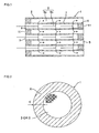
- a plugged honeycomb structure 1 including a honeycomb structured body 2 where a plurality of cells 9 communicating between an inlet end surface 3 which becomes an inlet side of a fluid and an outlet end surface 5 which becomes an outlet side of the fluid are partitioned by porous partition walls 7; and plugged portions 4 to plug open frontal areas of predetermined cells 9a on the side of the inlet end surface 3 and open frontal areas of remaining cells 9b on the side of the outlet end surface 5.
- the exhaust gas flows into the plugged honeycomb structure 1 through the inlet end surface 3.
- the soot included in the exhaust gas is removed, and then the exhaust gas flows out of the structure through the outlet end surface 5.
- the exhaust gas first flows into the cells 9b whose open frontal areas are not plugged on the inlet end surface 3 side of the plugged honeycomb structure 1 and are plugged on the outlet end surface 5 side.
- the exhaust gas passes through pores of the porous partition walls 7, moves to the cells 9a whose open frontal areas are plugged on the inlet end surface 3 side and are not plugged on the outlet end surface 5 side, and is discharged to the outside through the cells 9a.
- the partition walls 7 become filter layers, and the soot in the exhaust gas is caught by the partition walls 7, and deposited on the partition walls 7.
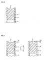
- the plugged portions 4 of the plugged honeycomb structure 1 are formed by charging the cells with a constituent material of the plugged portions in a slurried state or the like, followed by firing.
- a recess portion (a shrinkage cavity) 11 is generated at an end of each of the plugged portions 4 during the firing.
- the recess portion 11 is present at the end of the plugged portion 4 in this manner, the soot is easily deposited at the end of the plugged portion 4 on the inlet end surface 3 side.
- a treatment (regeneration) of burning and removing the deposited soot is periodically performed so that a pressure loss increased by the soot deposited in the filter with an elapse of time is decreased to return a filter performance to an initial state.
- the soot deposited at the ends of the plugged portions 4 is not easily completely burnt during the regeneration of the plugged honeycomb structure 1, and the unburnt soot remains as it is at the ends of the plugged portions 4.
- the soot which remains at the ends of the plugged portions 4 in this manner is gradually accumulated during the use for the long period of time, and the soot finally covers not only the ends of the plugged portions 4 but also the open frontal areas of the adjacent cells 9. In consequence, the pressure loss of the filter rapidly increases, which incurs the deterioration of fuel efficiency.
- Patent Document 1 has suggested a technology of densifying the surfaces of the plugged portions to decrease surface roughness so that the soot is not easily deposited in the plugged portions (see Patent Document 1).
- the cells are first charged with the constituent material of the plugged portions, followed by firing, as usual. Afterward, the end surfaces of the plugged honeycomb structure are spray-coated with a densifying material having regulated characteristics, to attach the material to the ends of the plugged portions.
- the densifying material to spray-coat the end surfaces of the plugged honeycomb structure enters the cells opened in the end surfaces of the plugged honeycomb structure, and also adheres to the surfaces of the partition walls in the vicinity of the open frontal areas of the cells. Therefore, not only the ends of the plugged portions but also the partition walls are densified.
- the porous partition walls by which the cells are partitioned function as the filter layers for catching the soot. Therefore, when the densifying material adheres to part of the partition walls to densify the walls and hence the exhaust gas does not easily pass through the walls, areas of the filter layers decrease, which incurs the deterioration of an ability to collect the soot and the increase of the pressure loss.
- the total length of the plugged honeycomb structure increases, which becomes a problem during the canning of the plugged honeycomb structure. That is, when the plugged honeycomb structure is used as a filter such as a DPF, as shown in Fig. 8 , a holding member 22 constituted of a ceramic fiber mat or the like is usually wound around an outer peripheral wall of the plugged honeycomb structure 1. Moreover, the structure is usually received (canned) in a cylindrical metal container 20 in a state where the structure is bound with retainer rings 21 around the ends of the structure.
- the present invention has been developed in view of such conventional situations, and an object thereof is to provide a plugged honeycomb structure which does not decrease an area of a filter layer or does not increase the total length thereof, but can suppress the deposition of soot at ends of plugged portions on an inlet end surface side or the generation of end-surface cracks on an outlet end surface side during regeneration, when the plugged honeycomb structure is used as a filter such as a DPF.
- the following plugged honeycomb structure is provided.
- the invention also provides the method of making a plugged honeycomb structure as set out in claim 4.
- a region having a width of at least 20 mm from an outer periphery of each end surface is subjected to a smoothing treatment by end-surface polishing so.that a depth of a recess portion generated at an end of each plugged portion during firing is decreased. Consequently, in the region on the side of the inlet end surface, soot is not easily deposited at the ends of the plugged portions. In consequence, it is possible to suppress the clogging of open frontal areas of cells due to the deposition of the soot which is unburnt and remains during regeneration. It is possible to prevent the rapid increase of a pressure loss or the deterioration of fuel efficiency due to the increase.
- the depth of the recess portion at the end of each plugged portion becomes small. Therefore, it is possible to alleviate the concentration of a thermal stress on the recess portions during the regeneration and to suppress the generation of end-surface cracks. Moreover, these effects are realized by the smoothing treatment by the end-surface polishing. In consequence, a problem such as a damage during canning due to the decrease of an area of a filter layer or the increase of the total length of the plugged honeycomb structure does not occur.
- a plugged honeycomb structure 1 of the present invention includes a honeycomb structured body 2 where a plurality of cells 9 communicating between an inlet end surface 3 which becomes an inlet side of a fluid and an outlet end surface 5 which becomes an outlet side of the fluid are partitioned by porous partition walls 7; and plugged portions 4 to plug open frontal areas of predetermined cells 9a on the side of the inlet end surface 3 and open frontal areas of remaining cells 9b on the side of the outlet end surface 5.
- a basic purification mechanism is similar to the above-mentioned conventional plugged honeycomb structure. That is, an exhaust gas first flows into the cells 9b whose open frontal areas are not plugged on the inlet end surface 3 side of the plugged honeycomb structure 1 and are plugged on the outlet end surface 5 side thereof, and passes through pores of the porous partition walls 7. The exhaust gas moves to the cells 9a whose open frontal areas are plugged on the inlet end surface 3 side and are not plugged on the outlet end surface 5 side, and is discharged to the outside through the cells 9a. In this case, the partition walls 7 become filter layers, and soot in the exhaust gas is caught by the partition walls 7, and deposited on the partition walls 7.
- the plugged portions 4 are formed by charging the cells 9 with a constituent material of the plugged portions in a slurried state or the like, followed by firing.
- a recess portion (a shrinkage cavity) 11 is generated at an end of the plugged portion 4 during this firing.
- a depth of the recess portion 11 is usually from about 0.06 to 0.15 mm.
- a smoothing treatment by end-surface polishing is performed so that a depth of the recess portion 11 generated at the end of the plugged portion 4 during the firing becomes small.
- the depth H of the recess portion 11 at the end of the plugged portion 4 becomes small, whereby it is possible to alleviate the concentration of a thermal stress on the recess portion 11 during the regeneration. It is possible to suppress the generation of end-surface cracks. Moreover, these effects are realized by the smoothing treatment by the end-surface polishing. In consequence, unlike the above-mentioned conventional technology, a problem such as a damage during canning due to the decrease of an area of the filter layer or the increase of the total length of the plugged honeycomb structure 1 does not occur.
- the smoothing treatment by the end-surface polishing is preferably performed so that the depth H of the recess portion 11 becomes smaller than 0.02 mm.
- the depth H of the recess portion 11 is smaller than 0.02 mm, it is possible to remarkably effectively suppress the deposition of the soot at the ends of the plugged portions 4 and the concentration of the thermal stress on the recess portions 11 during the regeneration.
- the depth of the recess portion 11 can be measured by using, for example, an optical gauge.
- the region A subjected to the smoothing treatment by the end-surface polishing may be a region in excess of the width of 20 mm from the outer periphery of each of the inlet end surface 3 and the outlet end surface 5.
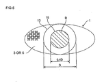
- an oxidation catalyst of Pt, Pd, Rh, Ag or the like is loaded onto the partition walls of the plugged honeycomb structure 1 to promote the burning of the soot during the regeneration, in a region B inside a circle 15 having, as a center thereof, a center of the largest circle 13 included in each of the inlet end surface 3 and the outlet end surface 5 and having a diameter 0.4D which is 40% of a diameter D of the largest circle 13 as shown in Fig.
- the smoothing treatment by the end-surface polishing preferably is not performed.
- Fig. 5 shows an example where the respective end surfaces (the inlet end surface 3 and the outlet end surface 5) are elliptic.
- the largest circle contained in the end surface becomes a circle which matches the outer periphery of the end surface (the circle having the same diameter and center as those of the end surface). Therefore, in this case, the region inside the circle having the same center as that of the end surface and having a diameter which is 40% of that of the end surface is a region which preferably is not subjected to the smoothing treatment by the end-surface polishing.
- the burning of the soot during the regeneration starts with a portion around the center of a section (the section vertical to an axial direction) of the plugged honeycomb structure in which a temperature easily rises owing to the exhaust gas, and burning heat generated there is transmitted to the periphery.
- the burning of the soot occurs in the whole plugged honeycomb structure. Therefore, in the region B, the smoothing treatment by the end-surface polishing preferably is not performed to prevent, as much as possible, the abrasive powder, which disturbs the contact between the soot and the oxidation catalyst, from adhering to the partition walls around this center.
- the plugged honeycomb structure 1 of the present invention there is not any special restriction on a material constituting the honeycomb structured body (the structure excluding the plugged portions 4) 2.
- the material include silicon carbide (SiC); a silicon-silicon carbide composite material formed by using silicon carbide (SiC) as an aggregate and silicon (Si) as a binder; silicon nitride; cordierite; mullite; alumina; spinel; a silicon carbide-cordierite composite material; lithium aluminum silicate; aluminum titanate; and an Fe-Cr-Al metal.
- the same material as that of the honeycomb structured body 2 is preferably used to decrease a thermal expansion difference between the plugged portions 4 and the honeycomb structured body 2.
- a thickness of the partition walls 7 is preferably from 178 to 508 ⁇ m (7 to 20 mil), more preferably from 203 to 406 ⁇ m (8 to 16 mil), and further preferably from 254 to 356 ⁇ m (10 to 14 mil).
- the thickness of the partition walls 7 is smaller than 178 ⁇ m (7 mil), the strength becomes insufficient, and a thermal shock resistance deteriorates sometimes.
- the thickness of the partition walls 7 exceeds 508 ⁇ m (20 mil), a pressure loss becomes excessively large sometimes.
- a cell density is preferably from 217 kilo to 543 kilo cells/m 2 (140 to 350 cells/in 2 (cpsi (cells per square inch))), more preferably from 248 kilo to 496 kilo cells/m 2 (160 to 320 cpsi), and further preferably from 310 kilo to 465 kilo cells/m 2 (200 to 300 cpsi).
- the cell density is smaller than 217 kilo cells/m 2 (140 cpsi), a contact efficiency with a fluid becomes insufficient sometimes.
- the cell density exceeds 543 kilo cells/m 2 (350 cpsi)
- the pressure loss becomes excessively large sometimes.
- a heretofore known method can be used as a method of preparing the honeycomb structured body (the structure excluding the plugged portions 4) 2 constituting the plugged honeycomb structure 1 of the present invention.
- a binder such as methylcellulose, hydroxypropoxyl cellulose, hydroxyethylcellulose, carboxymethylcellulose or polyvinyl alcohol, a pore former, a surfactant, and water as a solvent are added to the above material to obtain a kneaded material having plasticity.
- This kneaded material is extruded into a predetermined honeycomb shape, and then dried with microwaves, hot air or the like, followed by firing.
- the firing may be performed prior to forming the plugged portions 4, or may be performed together with the firing of the plugged portions 4 after forming the plugged portions 4 in the cells 9.
- a heretofore known method can be used as a method of plugging the cells 9.
- a sheet is attached to the end surface of the honeycomb structured body 2 prepared by the above method. Afterward, holes are made at positions of the sheet which correspond to the cells to be plugged. While this sheet is attached, the end surface of the honeycomb structured body 2 is immersed into a plugging slurry obtained by slurrying the constituent material of the plugged portions 4. Open ends of the cells to be plugged through the holes made in the sheet are charged with the plugging slurry.
- the honeycomb structured body is dried and fired to harden.
- the plugged honeycomb structure 1 of the present invention is obtained by plugging the cells 9 by such a method and then performing the smoothing treatment by the end-surface polishing.
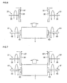
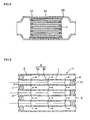
- Fig. 6 and Fig. 7 are explanatory views showing an example of a method of the smoothing treatment by the end-surface polishing.
- a pair of polishing tools 31 (a set of two polishing tools) each including around rotary plate 33, a rotary shaft 35 attached vertically to the center of one surface of the rotary plate 33, and a ring-like grindstone 37 attached to the other surface of the rotary plate 33.
- the pair of polishing tools 31 are arranged so that the surfaces of the rotary plates 33 to which the grindstones 37 are attached face each other and so that the rotary shafts 35 are positioned along the same axis.
- the rotary shafts 35 are rotated by a not-shown drive mechanism, thereby rotating the rotary plates 33 and the grindstones 37.
- the pair of polishing tools 31 are arranged movably in the axial direction of the polishing tools 31, whereby a space between the tools can be regulated.
- the centers of the end surfaces of the plugged honeycomb structure 1 subjected to the smoothing treatment by the end-surface polishing are held from both sides thereof in the axial direction by a pair of chuck tools 41 (a set of two chuck tools) each including a disc-like chuck portion 43 and a rotary shaft 45 attached vertically to the center of the surface of the chuck portion 43.
- the rotary shafts 45 are rotated by a not-shown drive mechanism, thereby rotating the plugged honeycomb structure 1.
- the chuck tools 41 are constituted so that the plugged honeycomb structure 1 is movable in a diametric direction while the plugged honeycomb structure 1 is held.
- the rotary shafts 35 of the polishing tools 31 are arranged in parallel with the rotary shafts 45 of the chuck tools 41, and the chuck tools 41 holding the plugged honeycomb structure 1 are brought close to the polishing tools present in the diametric direction of the plugged honeycomb structure 1.
- the respective end surfaces (the inlet end surface and the outlet end surface) of the plugged honeycomb structure 1 are brought into contact with the grindstones 37 of the polishing tools 31.
- the grindstones 37 of the polishing tools 31 are rotated at a high speed with a rotation number of about 50 to 500 rpm.
- the plugged honeycomb structure 1 held by the chuck tools 41 is rotated at a low speed with a rotation number of about 5 to 30 rpm.
- the end surfaces of the plugged honeycomb structure 1 are brought into contact with the grindstones 37, and are both rotated, whereby the end surfaces of the plugged honeycomb structure 1 are subjected to the smoothing treatment by the end-surface polishing.
- a polishing amount of the end-surface polishing in a depth direction can be regulated by controlling a space between the pair of polishing tools 31.
- a width of a region subjected to the smoothing treatment by the end-surface polishing can be regulated by controlling a distance between the rotary shaft 35 of the polishing tool 31 and the rotary shaft 45 of the chuck tool 41.
- a binder, a dispersant, water and the like were added to a raw material (obtained by mixing predetermined amounts of talc, alumina and kaolin) constituting cordierite, followed by kneading, to prepare a kneaded material.
- This kneaded material was extruded to obtain a honeycomb-like formed body (the honeycomb formed body).
- open frontal areas of predetermined cells on an inlet end surface side of the obtained honeycomb formed body and open frontal areas of the remaining cells on an outlet end surface side thereof were charged with a plugging material.
- the areas were charged with the plugging material so that the cells whose open frontal areas were charged with the plugging material and the cells which were not charged with the plugging material developed a checkered pattern in the respective end surfaces.
- a composition of the plugging material was the same as that of the honeycomb formed body.
- this honeycomb formed body was fired at a predetermined temperature for a predetermined period of time, to obtain a plugged honeycomb structure whose outer shape was a columnar shape with a diameter of 144 mm and a length of 152 mm.
- a partition wall thickness was 305 ⁇ m (12 mil)
- a cell density was 465 kilo cells/m 2 (300 cpsi)
- a cell shape was a quadrangular shape. It is to be noted that at this time, recess portions (shrinkage cavities) having a depth of about 0.11 to 0.12 mm were generated at ends of plugged portions of the obtained plugged honeycomb structure.
- Each plugged honeycomb structure was attached to an exhaust tube of a diesel engine. Then, the diesel engine was operated to circulate an exhaust gas through the plugged honeycomb structure, thereby depositing soot in the plugged honeycomb structure at a rate of 6 g/l. Afterward, an exhaust gas temperature was raised to about 600°C, and an exhaust gas flow rate was controlled at 2 m 3 /min. The soot deposited in the plugged honeycomb structure was burned by regulating time so that a regeneration efficiency obtained by the following equation (1) was from 50 to 60%. This regeneration cycle was repeated 20 times. Afterward, the plugged honeycomb structure was removed from the exhaust tube, and it was checked whether or not cracks were generated in the outlet end surface. When any cracks were not generated, the evaluation was "Good".
- An allowable limit value of a length of the plugged honeycomb structure was set, and a metal container for receiving (canning) the plugged honeycomb structure was prepared on the basis of the set value.
- the plugged honeycomb structure was pressed into and received in this metal container, and then cones were attached to an inlet and an outlet of the metal container. Then, while applying a vibration to this metal container with a vibration acceleration of 30 G and a vibration frequency of 100 Hz, the container was held at 150°C for ten minutes, a temperature was raised to 800°C, and the container was held for ten minutes. This heating/vibrating cycle was repeated 50 times.
- the plugged honeycomb structure was removed from the metal container, and it was confirmed whether or not cracks were generated in a contact portion of the structure with the metal container. When any cracks were not generated, the evaluation was "Good”. When the cracks were generated, the evaluation was "Bad”.
- the partition walls of the plugged honeycomb structure were coated with a slurry including an oxidation catalyst to load the oxidation catalyst onto the partition walls.
- this plugged honeycomb structure was placed into the metal container, and assembled into an exhaust system of a downstream portion of the diesel engine, together with an oxidation catalyst loading member prepared separately.
- the diesel engine was operated to circulate the exhaust gas through the plugged honeycomb structure, and 6 g/l of the soot was deposited in the plugged honeycomb structure.
- an exhaust gas temperature was raised to about 600°C, and held for five minutes, to perform a regeneration treatment of burning the soot deposited in the plugged honeycomb structure.
- the regeneration efficiency was obtained from the soot amount (the initial soot amount) prior to the regeneration and the soot amount after the regeneration by the above equation (1).
- the evaluation was "Good”.
- the evaluation was "Bad”.
- a plugged honeycomb structure prior to a smoothing treatment by end-surface polishing was obtained. End surfaces (an inlet end surface and an outlet end surface) of this plugged honeycomb structure were spray-coated with a densifying material, and then dried at about 500°C, to obtain the plugged honeycomb structure of Comparative Example 3.
- the densifying material was prepared by adding a binder, a pore former, a dispersant, water and the like to a raw material (obtained by mixing predetermined amounts of talc, alumina and kaolin) constituting cordierite, followed by kneading, and regulating a viscosity to be suitable for the spray-coating.
- a depth H of recess portions at ends of plugged portions of the structure spray-coated with the densifying material and dried was smaller than 0.02 mm.
- a crack resistance, a pressure loss increase ratio, canning properties and a regeneration performance were evaluated in the same manner as in Examples 1 to 5 and Comparative Example 1. The evaluation results are shown in Table 1.
- the plugged honeycomb structures of Examples 1 to 5 according to the embodiment of the present invention indicated high evaluation results of the crack resistance, the pressure loss increase ratio and the canning properties as compared with the plugged honeycomb structure of Comparative Example 2 which was not subjected to the smoothing treatment by the end-surface polishing.
- the plugged honeycomb structure of Comparative Example 3 in which the smoothing treatment by the end-surface polishing was not performed and the ends of the plugged portions were densified by the spray-coating of the densifying material, a total length of the structure became long, and hence the canning properties deteriorated.
- the densifying material adhered not only to the ends of the plugged portions but also to the partition walls functioning as filter layers.
- the result of the evaluation of the pressure loss increase ratio was also inferior to the plugged honeycomb structures of Examples 1 to 5. Moreover, in the plugged honeycomb structure of Comparative Example 1 in which the region subjected to the smoothing treatment by the end-surface polishing was a region having a width smaller than 20 mm from the outer periphery of each end surface, the region subjected to the treatment was excessively small. Therefore, a sufficient treatment effect could not be obtained, and the evaluations of the crack resistance and the pressure loss increase ratio were low.
- a plugged honeycomb structure of the present invention can suitably be used as a dust collecting filter such as a DPF.
Landscapes
- Physics & Mathematics (AREA)
- Geometry (AREA)
- Chemical & Material Sciences (AREA)
- Chemical Kinetics & Catalysis (AREA)
- Engineering & Computer Science (AREA)
- Mechanical Engineering (AREA)
- Ceramic Engineering (AREA)
- Inorganic Chemistry (AREA)
- Filtering Materials (AREA)
- Processes For Solid Components From Exhaust (AREA)
- Filtering Of Dispersed Particles In Gases (AREA)
- Porous Artificial Stone Or Porous Ceramic Products (AREA)
Applications Claiming Priority (1)
| Application Number | Priority Date | Filing Date | Title |
|---|---|---|---|
| JP2011072748A JP5220152B2 (ja) | 2011-03-29 | 2011-03-29 | 目封止ハニカム構造体 |
Publications (2)
| Publication Number | Publication Date |
|---|---|
| EP2508241A1 EP2508241A1 (en) | 2012-10-10 |
| EP2508241B1 true EP2508241B1 (en) | 2014-10-22 |
Family
ID=45894281
Family Applications (1)
| Application Number | Title | Priority Date | Filing Date |
|---|---|---|---|
| EP12161024.0A Active EP2508241B1 (en) | 2011-03-29 | 2012-03-23 | Plugged honeycomb structure |
Country Status (2)
| Country | Link |
|---|---|
| EP (1) | EP2508241B1 (enExample) |
| JP (1) | JP5220152B2 (enExample) |
Families Citing this family (1)
| Publication number | Priority date | Publication date | Assignee | Title |
|---|---|---|---|---|
| JP6757189B2 (ja) * | 2016-06-23 | 2020-09-16 | 日本碍子株式会社 | セグメント型ハニカム構造体の評価方法 |
Family Cites Families (9)
| Publication number | Priority date | Publication date | Assignee | Title |
|---|---|---|---|---|
| JP4699702B2 (ja) | 2004-01-30 | 2011-06-15 | 日本碍子株式会社 | ハニカム構造体及びその製造方法 |
| JP4927405B2 (ja) * | 2005-03-23 | 2012-05-09 | 日本碍子株式会社 | 目封止ハニカム構造体の製造方法 |
| WO2007037222A1 (ja) * | 2005-09-28 | 2007-04-05 | Ibiden Co., Ltd. | ハニカムフィルタ |
| JP2007144922A (ja) * | 2005-11-30 | 2007-06-14 | Hitachi Metals Ltd | セラミックハニカム構造体の製造方法 |
| JP5057815B2 (ja) * | 2006-05-17 | 2012-10-24 | イビデン株式会社 | ハニカム成形体用端面処理装置、ハニカム成形体の封止方法、及び、ハニカム構造体の製造方法 |
| WO2007132530A1 (ja) * | 2006-05-17 | 2007-11-22 | Ibiden Co., Ltd. | ハニカム成形体用端面処理装置、ハニカム成形体の封止方法、及び、ハニカム構造体の製造方法 |
| JP5162509B2 (ja) * | 2009-03-24 | 2013-03-13 | 日本碍子株式会社 | ハニカム成形体へのスリット形成方法 |
| JP5208836B2 (ja) * | 2009-03-31 | 2013-06-12 | 日本碍子株式会社 | ハニカム構造体の製造方法 |
| JP2009195905A (ja) * | 2009-04-13 | 2009-09-03 | Hitachi Metals Ltd | セラミックハニカムフィルタの製造方法 |
-
2011
- 2011-03-29 JP JP2011072748A patent/JP5220152B2/ja active Active
-
2012
- 2012-03-23 EP EP12161024.0A patent/EP2508241B1/en active Active
Also Published As
| Publication number | Publication date |
|---|---|
| JP2012206006A (ja) | 2012-10-25 |
| JP5220152B2 (ja) | 2013-06-26 |
| EP2508241A1 (en) | 2012-10-10 |
Similar Documents
| Publication | Publication Date | Title |
|---|---|---|
| EP2119487B1 (en) | Honeycomb structure and method for manufacturing the same | |
| US9289711B2 (en) | Plugged honeycomb structure | |
| JP6092841B2 (ja) | 集塵用ハニカムフィルタ | |
| JP5805039B2 (ja) | ハニカム構造体 | |
| CN204745876U (zh) | 蜂窝结构体 | |
| US20090252919A1 (en) | Honeycomb structure and method for manufacturing the same | |
| US10857499B2 (en) | Plugged honeycomb structure | |
| KR20080102179A (ko) | 허니콤 세그먼트, 허니콤 구조체 및 그 제조 방법 | |
| US10765986B2 (en) | Plugged honeycomb structure | |
| US10850223B2 (en) | Plugged honeycomb structure | |
| JP6014526B2 (ja) | ハニカム構造体 | |
| EP2221099B1 (en) | Honeycomb structure | |
| JP2016172653A (ja) | ハニカム構造体 | |
| EP2508241B1 (en) | Plugged honeycomb structure | |
| JP5972816B2 (ja) | ハニカム構造体 | |
| EP2505253B1 (en) | Plugged honeycomb structure | |
| JP6595194B2 (ja) | ハニカム構造体 | |
| US20170274311A1 (en) | Honeycomb filter | |
| EP2127720B1 (en) | Honeycomb structure | |
| JP6948273B2 (ja) | ハニカムフィルタ |
Legal Events
| Date | Code | Title | Description |
|---|---|---|---|
| PUAI | Public reference made under article 153(3) epc to a published international application that has entered the european phase |
Free format text: ORIGINAL CODE: 0009012 |
|
| AK | Designated contracting states |
Kind code of ref document: A1 Designated state(s): AL AT BE BG CH CY CZ DE DK EE ES FI FR GB GR HR HU IE IS IT LI LT LU LV MC MK MT NL NO PL PT RO RS SE SI SK SM TR |
|
| AX | Request for extension of the european patent |
Extension state: BA ME |
|
| 17P | Request for examination filed |
Effective date: 20130402 |
|
| REG | Reference to a national code |
Ref country code: DE Ref legal event code: R079 Ref document number: 602012003451 Country of ref document: DE Free format text: PREVIOUS MAIN CLASS: B01D0046240000 Ipc: B24B0007170000 |
|
| GRAP | Despatch of communication of intention to grant a patent |
Free format text: ORIGINAL CODE: EPIDOSNIGR1 |
|
| RIC1 | Information provided on ipc code assigned before grant |
Ipc: B24B 7/22 20060101ALI20131129BHEP Ipc: F01N 3/022 20060101ALI20131129BHEP Ipc: B24B 7/17 20060101AFI20131129BHEP Ipc: B01D 46/24 20060101ALI20131129BHEP |
|
| INTG | Intention to grant announced |
Effective date: 20131217 |
|
| GRAP | Despatch of communication of intention to grant a patent |
Free format text: ORIGINAL CODE: EPIDOSNIGR1 |
|
| INTG | Intention to grant announced |
Effective date: 20140610 |
|
| GRAS | Grant fee paid |
Free format text: ORIGINAL CODE: EPIDOSNIGR3 |
|
| GRAA | (expected) grant |
Free format text: ORIGINAL CODE: 0009210 |
|
| AK | Designated contracting states |
Kind code of ref document: B1 Designated state(s): AL AT BE BG CH CY CZ DE DK EE ES FI FR GB GR HR HU IE IS IT LI LT LU LV MC MK MT NL NO PL PT RO RS SE SI SK SM TR |
|
| REG | Reference to a national code |
Ref country code: GB Ref legal event code: FG4D |
|
| REG | Reference to a national code |
Ref country code: CH Ref legal event code: EP |
|
| REG | Reference to a national code |
Ref country code: AT Ref legal event code: REF Ref document number: 692377 Country of ref document: AT Kind code of ref document: T Effective date: 20141115 |
|
| REG | Reference to a national code |
Ref country code: IE Ref legal event code: FG4D |
|
| REG | Reference to a national code |
Ref country code: DE Ref legal event code: R096 Ref document number: 602012003451 Country of ref document: DE Effective date: 20141204 |
|
| REG | Reference to a national code |
Ref country code: NL Ref legal event code: VDEP Effective date: 20141022 |
|
| REG | Reference to a national code |
Ref country code: AT Ref legal event code: MK05 Ref document number: 692377 Country of ref document: AT Kind code of ref document: T Effective date: 20141022 |
|
| REG | Reference to a national code |
Ref country code: LT Ref legal event code: MG4D |
|
| PG25 | Lapsed in a contracting state [announced via postgrant information from national office to epo] |
Ref country code: NL Free format text: LAPSE BECAUSE OF FAILURE TO SUBMIT A TRANSLATION OF THE DESCRIPTION OR TO PAY THE FEE WITHIN THE PRESCRIBED TIME-LIMIT Effective date: 20141022 Ref country code: LT Free format text: LAPSE BECAUSE OF FAILURE TO SUBMIT A TRANSLATION OF THE DESCRIPTION OR TO PAY THE FEE WITHIN THE PRESCRIBED TIME-LIMIT Effective date: 20141022 Ref country code: FI Free format text: LAPSE BECAUSE OF FAILURE TO SUBMIT A TRANSLATION OF THE DESCRIPTION OR TO PAY THE FEE WITHIN THE PRESCRIBED TIME-LIMIT Effective date: 20141022 Ref country code: IS Free format text: LAPSE BECAUSE OF FAILURE TO SUBMIT A TRANSLATION OF THE DESCRIPTION OR TO PAY THE FEE WITHIN THE PRESCRIBED TIME-LIMIT Effective date: 20150222 Ref country code: ES Free format text: LAPSE BECAUSE OF FAILURE TO SUBMIT A TRANSLATION OF THE DESCRIPTION OR TO PAY THE FEE WITHIN THE PRESCRIBED TIME-LIMIT Effective date: 20141022 Ref country code: NO Free format text: LAPSE BECAUSE OF FAILURE TO SUBMIT A TRANSLATION OF THE DESCRIPTION OR TO PAY THE FEE WITHIN THE PRESCRIBED TIME-LIMIT Effective date: 20150122 Ref country code: PT Free format text: LAPSE BECAUSE OF FAILURE TO SUBMIT A TRANSLATION OF THE DESCRIPTION OR TO PAY THE FEE WITHIN THE PRESCRIBED TIME-LIMIT Effective date: 20150223 |
|
| PG25 | Lapsed in a contracting state [announced via postgrant information from national office to epo] |
Ref country code: GR Free format text: LAPSE BECAUSE OF FAILURE TO SUBMIT A TRANSLATION OF THE DESCRIPTION OR TO PAY THE FEE WITHIN THE PRESCRIBED TIME-LIMIT Effective date: 20150123 Ref country code: HR Free format text: LAPSE BECAUSE OF FAILURE TO SUBMIT A TRANSLATION OF THE DESCRIPTION OR TO PAY THE FEE WITHIN THE PRESCRIBED TIME-LIMIT Effective date: 20141022 Ref country code: PL Free format text: LAPSE BECAUSE OF FAILURE TO SUBMIT A TRANSLATION OF THE DESCRIPTION OR TO PAY THE FEE WITHIN THE PRESCRIBED TIME-LIMIT Effective date: 20141022 Ref country code: LV Free format text: LAPSE BECAUSE OF FAILURE TO SUBMIT A TRANSLATION OF THE DESCRIPTION OR TO PAY THE FEE WITHIN THE PRESCRIBED TIME-LIMIT Effective date: 20141022 Ref country code: CY Free format text: LAPSE BECAUSE OF FAILURE TO SUBMIT A TRANSLATION OF THE DESCRIPTION OR TO PAY THE FEE WITHIN THE PRESCRIBED TIME-LIMIT Effective date: 20141022 Ref country code: SE Free format text: LAPSE BECAUSE OF FAILURE TO SUBMIT A TRANSLATION OF THE DESCRIPTION OR TO PAY THE FEE WITHIN THE PRESCRIBED TIME-LIMIT Effective date: 20141022 Ref country code: RS Free format text: LAPSE BECAUSE OF FAILURE TO SUBMIT A TRANSLATION OF THE DESCRIPTION OR TO PAY THE FEE WITHIN THE PRESCRIBED TIME-LIMIT Effective date: 20141022 Ref country code: AT Free format text: LAPSE BECAUSE OF FAILURE TO SUBMIT A TRANSLATION OF THE DESCRIPTION OR TO PAY THE FEE WITHIN THE PRESCRIBED TIME-LIMIT Effective date: 20141022 |
|
| REG | Reference to a national code |
Ref country code: DE Ref legal event code: R097 Ref document number: 602012003451 Country of ref document: DE |
|
| PG25 | Lapsed in a contracting state [announced via postgrant information from national office to epo] |
Ref country code: DK Free format text: LAPSE BECAUSE OF FAILURE TO SUBMIT A TRANSLATION OF THE DESCRIPTION OR TO PAY THE FEE WITHIN THE PRESCRIBED TIME-LIMIT Effective date: 20141022 Ref country code: RO Free format text: LAPSE BECAUSE OF FAILURE TO SUBMIT A TRANSLATION OF THE DESCRIPTION OR TO PAY THE FEE WITHIN THE PRESCRIBED TIME-LIMIT Effective date: 20141022 Ref country code: SK Free format text: LAPSE BECAUSE OF FAILURE TO SUBMIT A TRANSLATION OF THE DESCRIPTION OR TO PAY THE FEE WITHIN THE PRESCRIBED TIME-LIMIT Effective date: 20141022 Ref country code: CZ Free format text: LAPSE BECAUSE OF FAILURE TO SUBMIT A TRANSLATION OF THE DESCRIPTION OR TO PAY THE FEE WITHIN THE PRESCRIBED TIME-LIMIT Effective date: 20141022 Ref country code: EE Free format text: LAPSE BECAUSE OF FAILURE TO SUBMIT A TRANSLATION OF THE DESCRIPTION OR TO PAY THE FEE WITHIN THE PRESCRIBED TIME-LIMIT Effective date: 20141022 |
|
| PLBE | No opposition filed within time limit |
Free format text: ORIGINAL CODE: 0009261 |
|
| STAA | Information on the status of an ep patent application or granted ep patent |
Free format text: STATUS: NO OPPOSITION FILED WITHIN TIME LIMIT |
|
| PG25 | Lapsed in a contracting state [announced via postgrant information from national office to epo] |
Ref country code: IT Free format text: LAPSE BECAUSE OF FAILURE TO SUBMIT A TRANSLATION OF THE DESCRIPTION OR TO PAY THE FEE WITHIN THE PRESCRIBED TIME-LIMIT Effective date: 20141022 |
|
| 26N | No opposition filed |
Effective date: 20150723 |
|
| PG25 | Lapsed in a contracting state [announced via postgrant information from national office to epo] |
Ref country code: LU Free format text: LAPSE BECAUSE OF FAILURE TO SUBMIT A TRANSLATION OF THE DESCRIPTION OR TO PAY THE FEE WITHIN THE PRESCRIBED TIME-LIMIT Effective date: 20150323 Ref country code: MC Free format text: LAPSE BECAUSE OF FAILURE TO SUBMIT A TRANSLATION OF THE DESCRIPTION OR TO PAY THE FEE WITHIN THE PRESCRIBED TIME-LIMIT Effective date: 20141022 |
|
| REG | Reference to a national code |
Ref country code: CH Ref legal event code: PL |
|
| REG | Reference to a national code |
Ref country code: FR Ref legal event code: ST Effective date: 20151130 |
|
| REG | Reference to a national code |
Ref country code: IE Ref legal event code: MM4A |
|
| PG25 | Lapsed in a contracting state [announced via postgrant information from national office to epo] |
Ref country code: LI Free format text: LAPSE BECAUSE OF NON-PAYMENT OF DUE FEES Effective date: 20150331 Ref country code: CH Free format text: LAPSE BECAUSE OF NON-PAYMENT OF DUE FEES Effective date: 20150331 Ref country code: IE Free format text: LAPSE BECAUSE OF NON-PAYMENT OF DUE FEES Effective date: 20150323 |
|
| PG25 | Lapsed in a contracting state [announced via postgrant information from national office to epo] |
Ref country code: SI Free format text: LAPSE BECAUSE OF FAILURE TO SUBMIT A TRANSLATION OF THE DESCRIPTION OR TO PAY THE FEE WITHIN THE PRESCRIBED TIME-LIMIT Effective date: 20141022 Ref country code: FR Free format text: LAPSE BECAUSE OF NON-PAYMENT OF DUE FEES Effective date: 20150331 |
|
| GBPC | Gb: european patent ceased through non-payment of renewal fee |
Effective date: 20160323 |
|
| PG25 | Lapsed in a contracting state [announced via postgrant information from national office to epo] |
Ref country code: MT Free format text: LAPSE BECAUSE OF FAILURE TO SUBMIT A TRANSLATION OF THE DESCRIPTION OR TO PAY THE FEE WITHIN THE PRESCRIBED TIME-LIMIT Effective date: 20141022 |
|
| PG25 | Lapsed in a contracting state [announced via postgrant information from national office to epo] |
Ref country code: GB Free format text: LAPSE BECAUSE OF NON-PAYMENT OF DUE FEES Effective date: 20160323 |
|
| PG25 | Lapsed in a contracting state [announced via postgrant information from national office to epo] |
Ref country code: BG Free format text: LAPSE BECAUSE OF FAILURE TO SUBMIT A TRANSLATION OF THE DESCRIPTION OR TO PAY THE FEE WITHIN THE PRESCRIBED TIME-LIMIT Effective date: 20141022 Ref country code: HU Free format text: LAPSE BECAUSE OF FAILURE TO SUBMIT A TRANSLATION OF THE DESCRIPTION OR TO PAY THE FEE WITHIN THE PRESCRIBED TIME-LIMIT; INVALID AB INITIO Effective date: 20120323 Ref country code: SM Free format text: LAPSE BECAUSE OF FAILURE TO SUBMIT A TRANSLATION OF THE DESCRIPTION OR TO PAY THE FEE WITHIN THE PRESCRIBED TIME-LIMIT Effective date: 20141022 |
|
| PG25 | Lapsed in a contracting state [announced via postgrant information from national office to epo] |
Ref country code: TR Free format text: LAPSE BECAUSE OF FAILURE TO SUBMIT A TRANSLATION OF THE DESCRIPTION OR TO PAY THE FEE WITHIN THE PRESCRIBED TIME-LIMIT Effective date: 20141022 |
|
| PG25 | Lapsed in a contracting state [announced via postgrant information from national office to epo] |
Ref country code: BE Free format text: LAPSE BECAUSE OF FAILURE TO SUBMIT A TRANSLATION OF THE DESCRIPTION OR TO PAY THE FEE WITHIN THE PRESCRIBED TIME-LIMIT Effective date: 20141022 |
|
| PG25 | Lapsed in a contracting state [announced via postgrant information from national office to epo] |
Ref country code: MK Free format text: LAPSE BECAUSE OF FAILURE TO SUBMIT A TRANSLATION OF THE DESCRIPTION OR TO PAY THE FEE WITHIN THE PRESCRIBED TIME-LIMIT Effective date: 20141022 |
|
| PG25 | Lapsed in a contracting state [announced via postgrant information from national office to epo] |
Ref country code: AL Free format text: LAPSE BECAUSE OF FAILURE TO SUBMIT A TRANSLATION OF THE DESCRIPTION OR TO PAY THE FEE WITHIN THE PRESCRIBED TIME-LIMIT Effective date: 20141022 |
|
| PGFP | Annual fee paid to national office [announced via postgrant information from national office to epo] |
Ref country code: DE Payment date: 20260128 Year of fee payment: 15 |