EP2508052B1 - Refroidissement d'air - Google Patents
Refroidissement d'air Download PDFInfo
- Publication number
- EP2508052B1 EP2508052B1 EP10784567.9A EP10784567A EP2508052B1 EP 2508052 B1 EP2508052 B1 EP 2508052B1 EP 10784567 A EP10784567 A EP 10784567A EP 2508052 B1 EP2508052 B1 EP 2508052B1
- Authority
- EP
- European Patent Office
- Prior art keywords
- air
- shutter
- fans
- outlet
- inlet
- Prior art date
- Legal status (The legal status is an assumption and is not a legal conclusion. Google has not performed a legal analysis and makes no representation as to the accuracy of the status listed.)
- Active
Links
- 238000001816 cooling Methods 0.000 title claims description 58
- 239000003570 air Substances 0.000 claims description 135
- 238000010438 heat treatment Methods 0.000 claims description 21
- 239000012080 ambient air Substances 0.000 claims description 8
- 238000001914 filtration Methods 0.000 claims description 2
- 238000004140 cleaning Methods 0.000 description 11
- 230000000694 effects Effects 0.000 description 5
- 238000005057 refrigeration Methods 0.000 description 3
- 238000010586 diagram Methods 0.000 description 2
- 238000012986 modification Methods 0.000 description 1
- 230000004048 modification Effects 0.000 description 1
- 239000004065 semiconductor Substances 0.000 description 1
Images


Classifications
-
- H—ELECTRICITY
- H05—ELECTRIC TECHNIQUES NOT OTHERWISE PROVIDED FOR
- H05K—PRINTED CIRCUITS; CASINGS OR CONSTRUCTIONAL DETAILS OF ELECTRIC APPARATUS; MANUFACTURE OF ASSEMBLAGES OF ELECTRICAL COMPONENTS
- H05K7/00—Constructional details common to different types of electric apparatus
- H05K7/20—Modifications to facilitate cooling, ventilating, or heating
- H05K7/20009—Modifications to facilitate cooling, ventilating, or heating using a gaseous coolant in electronic enclosures
- H05K7/20136—Forced ventilation, e.g. by fans
- H05K7/20145—Means for directing air flow, e.g. ducts, deflectors, plenum or guides
-
- H—ELECTRICITY
- H05—ELECTRIC TECHNIQUES NOT OTHERWISE PROVIDED FOR
- H05K—PRINTED CIRCUITS; CASINGS OR CONSTRUCTIONAL DETAILS OF ELECTRIC APPARATUS; MANUFACTURE OF ASSEMBLAGES OF ELECTRICAL COMPONENTS
- H05K7/00—Constructional details common to different types of electric apparatus
- H05K7/20—Modifications to facilitate cooling, ventilating, or heating
- H05K7/20536—Modifications to facilitate cooling, ventilating, or heating for racks or cabinets of standardised dimensions, e.g. electronic racks for aircraft or telecommunication equipment
- H05K7/20554—Forced ventilation of a gaseous coolant
- H05K7/20572—Forced ventilation of a gaseous coolant within cabinets for removing heat from sub-racks, e.g. plenum
-
- H—ELECTRICITY
- H05—ELECTRIC TECHNIQUES NOT OTHERWISE PROVIDED FOR
- H05K—PRINTED CIRCUITS; CASINGS OR CONSTRUCTIONAL DETAILS OF ELECTRIC APPARATUS; MANUFACTURE OF ASSEMBLAGES OF ELECTRICAL COMPONENTS
- H05K7/00—Constructional details common to different types of electric apparatus
- H05K7/20—Modifications to facilitate cooling, ventilating, or heating
- H05K7/20009—Modifications to facilitate cooling, ventilating, or heating using a gaseous coolant in electronic enclosures
- H05K7/20209—Thermal management, e.g. fan control
-
- H—ELECTRICITY
- H05—ELECTRIC TECHNIQUES NOT OTHERWISE PROVIDED FOR
- H05K—PRINTED CIRCUITS; CASINGS OR CONSTRUCTIONAL DETAILS OF ELECTRIC APPARATUS; MANUFACTURE OF ASSEMBLAGES OF ELECTRICAL COMPONENTS
- H05K7/00—Constructional details common to different types of electric apparatus
- H05K7/20—Modifications to facilitate cooling, ventilating, or heating
- H05K7/20536—Modifications to facilitate cooling, ventilating, or heating for racks or cabinets of standardised dimensions, e.g. electronic racks for aircraft or telecommunication equipment
- H05K7/206—Air circulating in closed loop within cabinets wherein heat is removed through air-to-air heat-exchanger
-
- H—ELECTRICITY
- H05—ELECTRIC TECHNIQUES NOT OTHERWISE PROVIDED FOR
- H05K—PRINTED CIRCUITS; CASINGS OR CONSTRUCTIONAL DETAILS OF ELECTRIC APPARATUS; MANUFACTURE OF ASSEMBLAGES OF ELECTRICAL COMPONENTS
- H05K7/00—Constructional details common to different types of electric apparatus
- H05K7/20—Modifications to facilitate cooling, ventilating, or heating
- H05K7/20536—Modifications to facilitate cooling, ventilating, or heating for racks or cabinets of standardised dimensions, e.g. electronic racks for aircraft or telecommunication equipment
- H05K7/20618—Air circulating in different modes under control of air guidance flaps
-
- H—ELECTRICITY
- H05—ELECTRIC TECHNIQUES NOT OTHERWISE PROVIDED FOR
- H05K—PRINTED CIRCUITS; CASINGS OR CONSTRUCTIONAL DETAILS OF ELECTRIC APPARATUS; MANUFACTURE OF ASSEMBLAGES OF ELECTRICAL COMPONENTS
- H05K7/00—Constructional details common to different types of electric apparatus
- H05K7/20—Modifications to facilitate cooling, ventilating, or heating
- H05K7/20536—Modifications to facilitate cooling, ventilating, or heating for racks or cabinets of standardised dimensions, e.g. electronic racks for aircraft or telecommunication equipment
- H05K7/207—Thermal management, e.g. cabinet temperature control
Definitions
- the present invention relates to air cooling of equipment and is more particularly, although not exclusively, concerned with the use of air at ambient temperature to effect cooling of electronic equipment.
- Cooling is required to maintain optimum operation of electronic equipment and it is well known to use refrigeration units to effect such cooling. In such cases, the refrigeration unit may use more energy than the equipment it is intended to cool.
- US patent 5 934 368 assigned to Hitachi, Ltd shows electronic apparatus having a hygrometer and temperature sensors, a dehumidifier and heater means for controlling the relative humidity and dewpoint temperature in relation to the surface temperature of semiconductor devices in the apparatus.
- ambient air cooling apparatus comprising: a chamber in which items to be cooled are located; an air inlet; at least one air outlet; at least one fan for drawing air from said air inlet, through said chamber and over the items to be cooled, and to said at least one air outlet; a heater for heating air within said cooling apparatus; and a controller for controlling the operation of said heater and said at least one fan, said at least one fan further including four fans for drawing air through the apparatus, wherein said fans are operated in pairs, and wherein a first pair of fans is arranged to draw air through the apparatus to a first outlet and a second pair of fans is arranged to draw air into an intermediate chamber connected to a second outlet and to a heater chamber in which said heater is mounted, said second pair of fans being separated from said second outlet by an outlet shutter, the outlet shutter being powered and movable between a fully closed position, a fully open position, and at least one intermediate position.
- the apparatus may include a filter attached to said air inlet for filtering the incoming air.
- the filter comprises a cyclonic filter. Said cyclonic filter may also operate to mix heated air from said heater with air from said air inlet.
- said air inlet includes a baffle.
- a first sensor may be located adjacent said baffle for determining the temperature of air at said air inlet.
- a second sensor may be located in said chamber for determining the temperature of air in said chamber.
- said air inlet includes an inlet shutter for controlling the ingress of air into the apparatus.
- Said inlet shutter may be powered and can be moved between a fully open position and a fully closed position.
- each fan has an associated backflow shutter that closes when the fan is non-operational.
- Said outlet shutter may be powered and can be moved between one of four positions, a fully closed position, a fully open position, a first intermediate position and a second intermediate position.
- said second pair of fans is separated from said heater chamber by a bypass shutter.
- Said bypass shutter may be powered and can be moved between a fully closed position and a fully open position.
- said controller is operable for receiving signals from said first and second sensors and for controlling said inlet shutter, said outlet shutter, said bypass shutter, said heater and said fans in accordance with said signals to effect optimal cooling of said items.
- Flow control means may also be provided within said chamber for balancing air flow over said items to be cooled.
- the present invention will be described with reference to cooling of a radar array but it will be appreciated that it can be used for cooling of any suitable electrical or electronic equipment where the operating temperature of the equipment to be cooled is greater than the ambient air temperature.
- the ambient air temperature is considerably less than the operating temperature of the radar array which can be around 70°C.
- cooling system in accordance with the present invention when used with a radar system will be described in detail below with respect to different operation modes according to the ambient air temperature at the location where the radar system is located.
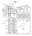
- cooling apparatus 100 is shown.
- the apparatus 100 an air inlet 105 having a baffle 110 and an inlet shutter 115.
- the baffle 110 prevents air from directly entering the apparatus 100 and, with the air control shutter 115, controls the flow rate of air entering the apparatus 100.
- the inlet shutter 115 is powered so that it can be operated to move from a fully open position, allowing air to enter the apparatus 100, to a closed position, preventing air from entering the apparatus 100. These positions are not shown in Figure 1 but are shown in the subsequent Figures.
- the air inlet 105 is connected to an air cleaning system 120 which comprises a cyclonic filter 125 through which air is directed for cleaning.
- the air cleaning system 120 includes an outlet 130 through which debris that is removed from the air is ejected.
- the cyclonic filter 125 includes guide vanes 135 that create a vortex so that unwanted debris is removed from the air and ejected through the outlet 130.
- a conduit 140 connects the air cleaning system 120 to a plenum chamber 145 in which the items to be cooled are located, for example, transmit/receive elements of a radar system that are referenced as 150a, 150b, 150c, 150d, 150e and 150f.
- the elements 150a, 150b, 150c, 150d, 150e and 150f are located in a first portion 145a of the plenum chamber 145 so that air is drawn over each element 150a, 150b, 150c, 150d, 150e, 150f to effect their cooling.
- air may be drawn through the elements 150a, 150b, 150c, 150d, 150e, 150f instead of over the elements if each element has cooling fins formed as an integral part of the element. In this case, the air is drawn through the element and over the cooling fins.
- cyclonic filter 125 is illustrated in and described with reference to Figure 1 , more than one cyclonic filter can be utilised. In one embodiment of the present invention, there are four cyclonic filters 125 connected between the air inlet 105 and the plenum chamber 145.
- the flow rate of air flowing to each of the elements 150a, 150b, 150c, 150d, 150e, 150f to be cooled is controlled by fixed inlets 155a, 155b and 155c.
- elements 150a and 150f require different flow rates for cooling to that required by elements 150b, 150c, 150d, 150e and hence inlets 155a and 155c are different to inlet 155b so that the air flow over all the element is balanced correctly for optimal cooling.
- each item to be cooled may require the same amount of air for cooling and in that case, inlets 155a, 155b and 155c may be a single inlet allowing air to flow at a particular flow rate.
- Air from elements 150a and 150f rejoins the air from elements 150b, 150c, 150d and 150e via to exit the first portion 145a of the plenum chamber 145 via outlet 155 into a second portion 145b thereof.
- the second portion 145b of the plenum chamber 145 houses four centrifugal fans 160a, 160b, 160c, 160d that draw air into the inlet 105, through the air cleaning system 120 and conduit 140, over the elements 150a, 150b, 150c, 150c, 150d, 150e, 150f in the first portion 145a of the plenum chamber 145, and into the second portion 145b of the plenum chamber 145.
- Each fan 160a, 160b, 160c, 160d is located in a channel 165a, 165b, 165c, 165d and has a backflow shutter 170a, 170b, 170c, 170d, also located in channel 165a, 165b, 165c, 165d and associated therewith.
- Backflow shutters 170a, 170b, 170c, 170d are not powered and are opened by suction when associated fans 160a, 160b, 160c, 160d are operating. When a fan is not operating the associated backflow shutter is closed as there is no suction from the fan to keep the backflow shutter open.
- the fans 160a, 160b, 160c, 160d are grouped together in pairs for operation, that is, fans 160a and 160b form a first pair that are operated together and fans 160c and 160d form a second pair that are operated together.
- Channels 165c and 165d are connected to outlets 175c and 175d and fans 160c and 160d draw a portion of the air in the plenum chamber 145 out to the outlets 175c and 175d where the air is expelled to atmosphere.
- Channels 165a and 165b are connected to a chamber 180 that is defined by a bypass shutter 185 and an outlet shutter 190.
- Outlet shutter 190 is connected to an outlet 190a so that when outlet shutter 190 is at least partially open, air is expelled to atmosphere.
- Bypass shutter 185 is connected to a heating chamber 195 in which a thermostatically controlled heater 195a is located. Heating chamber 195 is also connected to air cleaning system 120 as shown.
- the bypass shutter 185 is powered so that it can be operated to move from a fully open position, allowing air to enter heating chamber 195, to a fully closed position, preventing air from entering the heating chamber 195.
- Exit shutter 190 is powered so that it can operate to move between a fully open position, a fully closed position and two intermediate partially open positions.
- the operation of the exit shutter 190 will be described in more detail with reference to Figures 2 to 4 below.
- exit shutter 190 is described as having only two intermediate positions, it will be appreciated that it can have any number of intermediate positions depending on the particular application.
- the apparatus 100 also includes temperature sensors 107 and 157, shown schematically in Figure 1 .
- Sensor 107 is located near the inlet 105 to sense the temperature of the air being drawn into the apparatus 100.
- Sensor 157 is located in the first portion 145a of plenum chamber 145 between inlet 155b and the elements 150b, 150c, 150d, 150e to be cooled to sense the temperature of the air about to pass over the elements to be cooled.
- the apparatus 100 also includes a control unit (not shown in Figure 1 ) that controls the operation of the air control shutter 115, the fans 160a, 160b, 160c, 160d, and the heater 195a.
- the control unit also connected to temperature sensors 107 and 157 to use signals indicative of the air temperature at the inlet 105 and the first portion 145a of the plenum 145 for controlling the operation of the air control shutter 115, the fans 160a, 160b, 160c, 160d and the heater 195a.
- electrical heater strips are provided for anti-icing the air control shutter 115 when the ambient air temperature falls to a level at which the air control shutter 115 would ice up, for example, below 5°C. It may be advantageous that the heater 195a and the electrical heater strips on the air control shutter 115 operate in conjunction with one another.
- the air flow rate through the cooling apparatus 100 is controlled such that the flow rate through the exit shutter 190 is matched to the flow rate entering the air control shutter 115 as illustrated in and described with reference to Figures 3 and 4 .
- cooling apparatus 100 can be housed within a single housing (not shown) that surrounds the elements 150a, 150b, 150c, 150d, 150e, 150f to be cooled without affecting their performance.
- the cooling apparatus 100 is shown where the radar system is operating and the cooling apparatus operates in a first active mode of operation.
- the ambient temperature is in the range of between 5°C and 45°C and the radar system is in a full transmit power mode.
- the ambient temperature is above 5°C, there is no risk of the radar system or the cooling apparatus 100 suffering the problems associated with icing up.
- the heater 195a is off as there is no need to heat the air that is used for cooling as the air is at a temperature where no icing with occur.
- all four fans 160a, 160b, 160c, 160d are operating and therefore the associated backflow shutters 165a, 165b, 165c, 165d are also in the fully open position.
- Air is drawn into the air cleaning system 120, through the conduit 140, into the plenum chamber 145 and out through outlets 175c, 175d, 190a as exit shutter 190 is fully open.
- Inlet shutter 115 is fully open to maximise the amount of air being drawn into the apparatus 100.
- Bypass shutter 185 is fully closed so that no air is diverted through the heating chamber 195 and all the air being drawn through channels 170a, 170b by fans 160a, 160b passes to outlet 190a via the fully open exit shutter 190.
- An example of the total air flow rate through the cooling apparatus 100 is 1.0m 3 s -1 and the air temperature sensed by sensor 157 in plenum 145 is approximately the same as the air temperature sensed by sensor 107 at the inlet 105, that is, between 5°C and 45°C.
- the cooling apparatus 100 operates in the second and third modes of operation as will be described with reference to Figures 3 and 4 .
- the radar system is operational and in a full transmit power mode.
- the air temperature at the inlet 105 as sensed by sensor 107 is between -20°C and 5°C.
- the elements 150a, 150b, 150c, 150d, 150e, 150f still need to be cooled, it is not possible to use air directly from the inlet 105 as this may cause them to ice up and prevent optimal operation of the radar system.
- Fans 160c, 160d are non-operational and hence their associated backflow shutters 165c, 165d are closed.
- Fans 160a, 160b provide an air flow rate of 0.57m 3 s -1 of which 0.30m 3 s -1 is re-circulated through the cooling apparatus 100 via heating chamber 195.
- the inlet shutter 115 is fully open and the exit shutter 190 is partially closed, in a first intermediate position, so that a flow rate of 0.27m 3 s -1 is achieved through the exit shutter 190.
- Bypass shutter 185 is fully open so that a flow rate of 0.30m 3 s -1 passes through heating chamber 195 so that the air is heated and mixed with cold air coming in at the inlet 105, in the air cleaning system 120, prior to the mixed air passing through conduit 140 and into plenum chamber 145 to cool the elements 150a, 150b, 150c, 150d, 150e, 150f.
- the temperature of the air sensed by sensor 157 is between 5°C and 30°C which is warm enough to prevent icing up of the elements 150a, 150b, 150c, 150d, 150e, 150f.
- the heater 195a can adequately heat the air passing through the heating chamber 195 so that the air temperature at the sensor 157 is at least 5°C.
- the flow rate of the air exiting exit shutter 190 into outlet 190a is 0.27m 3 s -1 and the flow rate of the air entering the inlet 105 is also 0.27m 3 s -1 to maintain a fixed flow rate of 0.57m 3 s -1 through the cooling apparatus 100.
- the cooling apparatus 100 is arranged as shown in Figure 4 . Again, it is not possible to use air directly from the inlet 105 as this may cause the elements 150a, 150b, 150c, 150d, 150e, 150f to ice up and prevent optimal operation of the radar system. As with the embodiment described with reference to Figure 3 , fans 160c, 160d are non-operational and hence their associated backflow shutters 165c, 165d are closed. Fans 160a, 160b provide an air flow rate of 0.57m 3 s -1 of which 0.40m 3 s -1 is re-circulated through the cooling apparatus 100 via heating chamber 195.
- the inlet shutter 115 is fully open and the exit shutter 190 is partially closed, in a second intermediate position, so that a flow rate of 0.17m 3 s -1 is achieved through the exit shutter 190.
- Bypass shutter 185 is fully open so that a flow rate of 0.40m 3 s -1 passes through heating chamber 195 so that the air is heated and mixed with cold air coming in at the inlet 105, in the air cleaning system 120, prior to the mixed air passing through conduit 140 and into plenum chamber 145 to cool the elements 150a, 150b, 150c, 150d, 150e, 150f.
- the temperature of the air sensed by sensor 157 is between 5°C and 31 °C which is warm enough to prevent icing up of the elements 150a, 150b, 150c, 150d, 150e, 150f.
- the heater 195a can adequately heat the air passing through the heating chamber 195 so that the air temperature at the sensor 157 is at least 5°C.
- the flow rate of the air exiting exit shutter 190 into outlet 190a is 0.17m 3 s -1 and the flow rate of the air entering the inlet 105 is also 0.17m 3 s -1 to maintain a fixed flow rate of 0.57m 3 s -1 through the cooling apparatus 100.
- the cooling apparatus 100 can operate in a "pre-heat” mode as shown in Figure 5 .
- the "pre-heat” mode is used where the radar system has not been operational for some time so that no heat is being generated by the elements 150a, 150b, 150c, 150d, 150e, 150f and the ambient air temperature has fallen below 5°C.
- it is necessary to bring the air temperature up to a suitable temperature for operation of the radar system.
- fans160c, 160d are non-operational and hence their associated backflow shutters 165c, 165d are closed.
- Fans 160a, 160b provide a suitable air flow rate which re-circulated through the cooling apparatus 100 via heating chamber 195.
- the inlet shutter 115 and exit shutter 190 are both fully closed and the bypass shutter 185 is fully open so all the air in the apparatus 100 passes through heating chamber 195 so that the air is heated.
- the inlet shutter 115 is closed, there is no incoming cold air to be mixed with the warm air from the heating chamber 195 in the air cleaning system 120 and the warm air circulates within the apparatus 100, being heated as it passes through the heating chamber 195, until the temperature sensed by sensor 157 is between 5°C and 45°C.
- the inlet shutter 115 can be opened and the radar system made operational. Subsequent operation of the cooling apparatus 100 is as described above with reference to Figure 2 .
- the heater 195a operates on a thermostat so that the air does not become overheated.
- FIG. 6 illustrates a block diagram of a control system 300 for use with the cooling system of Figures 1 to 5 .
- the control system 300 comprises a control unit 305 connected to receive ambient temperature signals 310 from temperature sensor 107 located at the air inlet 105 and operating temperature signals 315 from temperature sensor 157 located in the plenum chamber 145a.
- the control unit 305 uses the temperature signals 310, 315 to control operation of fans 160a, 160b, 160c, 160d, heater 195a, outlet shutter 190, inlet shutter 115, bypass shutter 185 and anti-icing heating elements 115a.
- Control signals are sent to fans 160a, 160b along line 320 and to fans 160c, 160d along line 325.
- fans 160a, 160b operate as a pair and fans 160c, 160d operate as another pair.
- two control signals 320, 325 can be used.
- individual control signals may be sent to each fan 160a, 160b, 160c, 160d individually.
- Heater 195a receives control signals along line 330 and anti-icing heating elements 115a receives control signals along line 335. As discussed above, the control unit 305 may control the operation of the heater 195a and the anti-icing heating elements 115a so that they operate together when required. Alternatively, the control unit 305 may control the operation of the heater 195a separately to that of the anti-icing heating elements 115a.
- Exit shutter 190 receives control signals along line 340 to control whether it is closed, fully open, or in an intermediate position as discussed above.
- the exit shutter 190 effectively controls the air flow out exiting the cooling apparatus 100 ( Figures 1 to 5 ).
- Inlet shutter 115 receives control signals along line 345 to control whether it is fully open or fully closed. Inlet shutter 115 is controlled to balance the air flow within the cooling apparatus 100 as described above with reference to Figures 1 to 5 .
- Control signals are sent to the bypass shutter 185 along line 350 to control the air flow through the heater chamber 195 and hence over the heater 195a as described above with reference to Figures 1 to 5 .
- the first and second intermediate positions of the outlet shutter 190 can be such that the outlet shutter is open about two-thirds and one-third respectively of the fully open position. Naturally, these intermediate positions can be adjusted to suit the particular cooling application.
- the items to be cooled may comprise a plurality of modules, each module having a heat exchanger attached thereto.
- the cooling apparatus 100 operates to pull air through or over the heat exchangers to effect cooling of the modules.
- the apparatus of the present invention is scalable in that the arrangement described with reference to Figures 1 to 5 can form one layer of a stack where each layer cools a plurality of elements so that a two-dimensional array of items to be cooled can be cooled.
- any connections needed to the elements 150a, 150b, 150c, 150d, 150e, 150f within the cooling apparatus 100, or to components forming part of the cooling apparatus itself, can be made by in any suitable manner as is well known.
Landscapes
- Engineering & Computer Science (AREA)
- Microelectronics & Electronic Packaging (AREA)
- Physics & Mathematics (AREA)
- Thermal Sciences (AREA)
- Aviation & Aerospace Engineering (AREA)
- Cooling Or The Like Of Electrical Apparatus (AREA)
Claims (13)
- Appareil (100) de refroidissement d'air ambiant comprenant :une chambre (145) dans laquelle des articles à refroidir sont situés ;une entrée d' air (105) ;au moins une sortie d'air (175c, 175d, 190a) ;au moins un ventilateur (160) pour aspirer l'air à partir de ladite entrée d'air (105), à travers ladite chambre (145) et sur les articles à refroidir, et jusqu'à ladite au moins une sortie d'air (175c, 175d, 190a) ;un dispositif de chauffage (195a) pour chauffer l'air à l'intérieur dudit appareil de refroidissement (100) ; etun dispositif de commande (305) pour commander le fonctionnement dudit dispositif de chauffage (195a) et dudit au moins un ventilateur ;ledit au moins un ventilateur (160) comportant en outre quatre ventilateurs pour aspirer l'air à travers l'appareil, lesdits ventilateurs fonctionnant par paires, et une première paire de ventilateurs (160c, 160d) étant agencée pour aspirer l'air à travers l'appareil jusqu'à une première sortie (175c, 175d), et caractérisé en ce qu'une deuxième paire de ventilateurs (160a, 160b) est agencée pour aspirer l'air dans une chambre intermédiaire (180) reliée à une deuxième sortie (190a) et une chambre de dispositif de chauffage (195) dans laquelle ledit dispositif de chauffage (195a) est monté, ladite deuxième paire de ventilateurs étant séparée de ladite deuxième sortie par un obturateur de sortie (190), l'obturateur de sortie étant motorisé et déplaçable entre une position complètement fermée, une position complètement ouverte et au moins une position intermédiaire.
- Appareil selon la revendication 1, comprenant en outre un filtre (125) fixé à ladite entrée d'air (105) pour filtrer l'air entrant.
- Appareil selon la revendication 2, dans lequel ledit filtre (125) comprend un filtre cyclonique.
- Appareil selon la revendication 3, dans lequel ledit filtre (125) fonctionne aussi pour mélanger l'air chauffé provenant dudit dispositif de chauffage (195a) avec l'air provenant de ladite entrée d' air (105).
- Appareil selon l'une quelconque des revendications précédentes, dans lequel ladite entrée d'air (105) comporte un déflecteur (110).
- Appareil selon la revendication 5, comportant en outre un premier capteur (107) situé à proximité dudit déflecteur (110) pour déterminer la température de l'air au niveau de ladite entrée d' air (105).
- Appareil selon la revendication 6, comportant en outre un deuxième capteur (157) situé dans ladite chambre (145) pour déterminer la température de l'air dans ladite chambre.
- Appareil selon l'une quelconque des revendications précédentes, dans lequel ladite entrée d'air (105) comporte un obturateur d'entrée (115) pour commander l'entrée d'air dans l'appareil (100).
- Appareil selon la revendication 8, dans lequel ledit obturateur d'entrée (115) est motorisé et peut être déplacé entre une position complètement ouverte et une position complètement fermée.
- Appareil selon l'une quelconque des revendications précédentes, dans lequel ledit obturateur de sortie (190) peut être déplacé entre l'une parmi quatre positions, une position complètement fermée, une position complètement ouverte, une première position intermédiaire et une deuxième position intermédiaire.
- Appareil selon l'une quelconque des revendications précédentes, dans lequel ladite deuxième paire de ventilateurs (160a, 160b) est séparée de ladite chambre de dispositif de chauffage (195) par un obturateur de dérivation (185).
- Appareil selon les revendications 7, 8 et 11, dans lequel ledit dispositif de commande (305) peut fonctionner pour recevoir des signaux desdits premier et deuxième capteurs (107, 157) et pour commander ledit obturateur d'entrée (115), ledit obturateur de sortie (190), ledit obturateur de dérivation (185), ledit dispositif de chauffage (195a) et lesdits ventilateurs (160) en fonction desdits signaux.
- Appareil selon l'une quelconque des revendications précédentes, comportant en outre des moyens de commande de fluide (155) à l'intérieur de ladite chambre (145) pour équilibrer le flux d'air sur lesdits articles à refroidir.
Priority Applications (2)
| Application Number | Priority Date | Filing Date | Title |
|---|---|---|---|
| EP10784567.9A EP2508052B1 (fr) | 2009-12-02 | 2010-11-18 | Refroidissement d'air |
| PL10784567T PL2508052T3 (pl) | 2009-12-02 | 2010-11-18 | Chłodzenie powietrzem |
Applications Claiming Priority (4)
| Application Number | Priority Date | Filing Date | Title |
|---|---|---|---|
| EP09275120A EP2330881A1 (fr) | 2009-12-02 | 2009-12-02 | Refroidissement d'air |
| GB0921100A GB0921100D0 (en) | 2009-12-02 | 2009-12-02 | Air cooling |
| EP10784567.9A EP2508052B1 (fr) | 2009-12-02 | 2010-11-18 | Refroidissement d'air |
| PCT/GB2010/051919 WO2011067581A1 (fr) | 2009-12-02 | 2010-11-18 | Refroidissement à l'air |
Publications (2)
| Publication Number | Publication Date |
|---|---|
| EP2508052A1 EP2508052A1 (fr) | 2012-10-10 |
| EP2508052B1 true EP2508052B1 (fr) | 2015-04-01 |
Family
ID=43530114
Family Applications (1)
| Application Number | Title | Priority Date | Filing Date |
|---|---|---|---|
| EP10784567.9A Active EP2508052B1 (fr) | 2009-12-02 | 2010-11-18 | Refroidissement d'air |
Country Status (5)
| Country | Link |
|---|---|
| US (1) | US9497886B2 (fr) |
| EP (1) | EP2508052B1 (fr) |
| AU (1) | AU2010326371B2 (fr) |
| PL (1) | PL2508052T3 (fr) |
| WO (1) | WO2011067581A1 (fr) |
Families Citing this family (14)
| Publication number | Priority date | Publication date | Assignee | Title |
|---|---|---|---|---|
| US8054625B2 (en) * | 2009-04-21 | 2011-11-08 | Yahoo! Inc. | Cold row encapsulation for server farm cooling system |
| JP2012223033A (ja) * | 2011-04-13 | 2012-11-12 | Yaskawa Electric Corp | 電力変換装置 |
| FR2975254B1 (fr) * | 2011-05-13 | 2013-06-28 | Airbus Operations Sas | Procede de repartition d'air de refroidissement pour equipement electrique monte en baie avionique et aeronef equipe d'une telle baie |
| JP5883774B2 (ja) * | 2012-12-20 | 2016-03-15 | 株式会社日立製作所 | 制御装置及び制御装置の冷却方法 |
| US9713289B2 (en) | 2013-01-28 | 2017-07-18 | Ch2M Hill Engineers, Inc. | Modular pod |
| USD754664S1 (en) | 2013-03-15 | 2016-04-26 | Ch2M Hill Engineers, Inc. | Modular pod |
| CN203423892U (zh) * | 2013-05-23 | 2014-02-05 | 杭州华三通信技术有限公司 | 电子设备 |
| DE102013112977B4 (de) * | 2013-11-25 | 2015-08-06 | Pfannenberg Gmbh | Luftdurchtrittsvorrichtung zur Zuführung gereinigter Luft in einen Innenraum eines Schaltschrankes und Schaltschrank mit einer solchen Luftdurchtrittsvorrichtung |
| CN103763873B (zh) * | 2014-01-03 | 2016-08-17 | 东南大学 | 一种分区送风机柜 |
| US9788461B2 (en) * | 2014-07-30 | 2017-10-10 | Ciena Corporation | Airflow divider for balancing airflow in a modular chassis system |
| US10194557B2 (en) * | 2015-02-12 | 2019-01-29 | Cisco Technology, Inc. | Thermal management system |
| CN106659066A (zh) * | 2016-11-16 | 2017-05-10 | 合肥普望电子有限责任公司 | 一种电气设备专用电子除湿器 |
| CN107949202A (zh) * | 2017-10-30 | 2018-04-20 | 深圳市科华恒盛科技有限公司 | 一种电子设备箱 |
| WO2022235631A1 (fr) * | 2021-05-04 | 2022-11-10 | Vertiv Corporation | Armoires d'équipement électronique à plénums d'air configurables |
Family Cites Families (24)
| Publication number | Priority date | Publication date | Assignee | Title |
|---|---|---|---|---|
| US3870227A (en) * | 1972-08-10 | 1975-03-11 | Ranco Inc | Comfort temperature control system for a zone |
| SE415528B (sv) * | 1978-04-10 | 1980-10-13 | Dustcontrol Ab | Stoftavskiljare av cyklontyp, med kontinuerlig rensning av ett i apparaten fritt inskjutande finfilter |
| US4325716A (en) * | 1980-05-28 | 1982-04-20 | Livemore Gerald S V | Mixing chamber in combination with a dust cyclone separator |
| US4495545A (en) * | 1983-03-21 | 1985-01-22 | Northern Telecom Limited | Enclosure for electrical and electronic equipment with temperature equalization and control |
| CH664093A5 (en) | 1984-11-14 | 1988-02-15 | Escher Wyss Gmbh | Temp. controller for electronic equipment in enclosed spaces - comprising air heater and cooling unit mounted on rails for ease of access to other components |
| US4860163A (en) * | 1988-08-05 | 1989-08-22 | American Telephone And Telegraph Company | Communication equipment cabinet cooling arrangement |
| DE4211759C2 (de) * | 1992-04-08 | 1997-04-03 | Schroff Gmbh | Lüftereinschub |
| DE4330925C2 (de) | 1993-09-13 | 1997-03-20 | Loh Kg Rittal Werk | Kühlgerät für einen Schaltschrank oder ein Elektronikgehäuse mit Vereisungsschutzeinrichtung |
| JP3232908B2 (ja) | 1994-09-20 | 2001-11-26 | 株式会社日立製作所 | 電子装置 |
| US5791408A (en) * | 1996-02-12 | 1998-08-11 | Johnson Service Company | Air handling unit including control system that prevents outside air from entering the unit through an exhaust air damper |
| US6105875A (en) * | 1998-09-08 | 2000-08-22 | Lucent Technologies, Inc. | Direct air cooling of outdoor electronic cabinets |
| US6127663A (en) * | 1998-10-09 | 2000-10-03 | Ericsson Inc. | Electronics cabinet cooling system |
| US6142866A (en) * | 1999-03-18 | 2000-11-07 | Nokia Telecommunications, Oy | Method and apparatus for providing air circulation control for a base transceiver station |
| SE0001165D0 (sv) * | 2000-03-31 | 2000-03-31 | Ericsson Telefon Ab L M | Förfarande och anordning för att kyla elektronik |
| DE20120802U1 (de) | 2001-12-21 | 2003-02-13 | Siemens AG, 80333 München | Haubenförmiges Gehäuse für elektrische Komponenten |
| US8115145B2 (en) | 2004-11-29 | 2012-02-14 | Sanmina-Sci Corporation | Systems and methods for base station enclosures |
| CN100563412C (zh) | 2006-02-24 | 2009-11-25 | 华为技术有限公司 | 机柜温控装置、处理装置、系统及方法 |
| US10182516B2 (en) * | 2006-06-15 | 2019-01-15 | Valan R. Martini | Energy saving system and method for cooling computer data center and telecom equipment |
| US8721409B1 (en) * | 2007-07-31 | 2014-05-13 | Amazon Technologies, Inc. | Airflow control system with external air control |
| JP4951596B2 (ja) * | 2008-07-31 | 2012-06-13 | 株式会社日立製作所 | 冷却システム及び電子装置 |
| US8270154B2 (en) * | 2009-01-27 | 2012-09-18 | Microsoft Corporation | Self-contained and modular air-cooled containerized server cooling |
| US8151578B1 (en) * | 2009-06-25 | 2012-04-10 | Amazon Technologies, Inc. | Multi-mode cooling system with pre-dehumidification |
| ES2392775B1 (es) * | 2010-03-30 | 2013-10-18 | Advanced Shielding Technologies Europe S.L. | Sistema para el acondicionamiento del aire del espacio interior de un centro de procesamiento de datos |
| US9894808B2 (en) * | 2010-03-31 | 2018-02-13 | Amazon Technologies, Inc. | Compressed air cooling system for data center |
-
2010
- 2010-11-18 EP EP10784567.9A patent/EP2508052B1/fr active Active
- 2010-11-18 US US13/512,794 patent/US9497886B2/en active Active
- 2010-11-18 PL PL10784567T patent/PL2508052T3/pl unknown
- 2010-11-18 AU AU2010326371A patent/AU2010326371B2/en not_active Ceased
- 2010-11-18 WO PCT/GB2010/051919 patent/WO2011067581A1/fr active Application Filing
Also Published As
| Publication number | Publication date |
|---|---|
| US9497886B2 (en) | 2016-11-15 |
| EP2508052A1 (fr) | 2012-10-10 |
| WO2011067581A1 (fr) | 2011-06-09 |
| PL2508052T3 (pl) | 2015-09-30 |
| AU2010326371B2 (en) | 2015-01-15 |
| US20120227930A1 (en) | 2012-09-13 |
| AU2010326371A1 (en) | 2012-06-14 |
Similar Documents
| Publication | Publication Date | Title |
|---|---|---|
| EP2508052B1 (fr) | Refroidissement d'air | |
| US10925219B2 (en) | Climate control system and method for indoor horticulture | |
| US6742583B2 (en) | Cooling system for a cabinet | |
| US10451295B2 (en) | Equipment enclosure with multi-mode temperature control system | |
| US6131653A (en) | Method and apparatus for dehumidifying and conditioning air | |
| US8621884B2 (en) | AC unit with economizer and sliding damper assembly | |
| US8499575B2 (en) | Air-conditioning system for electronic components | |
| US9120690B2 (en) | Vortex air inlet system, compressor system and related method | |
| US20130219941A1 (en) | Integrated portable unit for providing electricity, air conditioning and heating | |
| CN113811720A (zh) | 具有动态智能空气管理系统的ptac单元 | |
| CN106969430A (zh) | 室外机及空调器 | |
| KR20040102020A (ko) | 공기조화기 | |
| GB2519308A (en) | Evaporative Cooler Apparatus and Method | |
| GB2540139B (en) | Combined ventilation, cooling and humidification system and method | |
| KR100346560B1 (ko) | 대형 공기조화기의 바이패스 장치 | |
| EP2330881A1 (fr) | Refroidissement d'air | |
| US9746200B2 (en) | Building ventilator | |
| CN210519291U (zh) | 顶置空调系统及集装箱数据中心 | |
| EP1920196B1 (fr) | Appareil de gestion de l'air | |
| CN215909164U (zh) | 厨房电器系统 | |
| CN110296482B (zh) | 用于空调室外机的送风组件、控制方法及空调室外机 | |
| CN107367028A (zh) | 温控系统及空调 | |
| IES84645Y1 (en) | An air handling apparatus |
Legal Events
| Date | Code | Title | Description |
|---|---|---|---|
| PUAI | Public reference made under article 153(3) epc to a published international application that has entered the european phase |
Free format text: ORIGINAL CODE: 0009012 |
|
| 17P | Request for examination filed |
Effective date: 20120523 |
|
| AK | Designated contracting states |
Kind code of ref document: A1 Designated state(s): AL AT BE BG CH CY CZ DE DK EE ES FI FR GB GR HR HU IE IS IT LI LT LU LV MC MK MT NL NO PL PT RO RS SE SI SK SM TR |
|
| DAX | Request for extension of the european patent (deleted) | ||
| 17Q | First examination report despatched |
Effective date: 20130507 |
|
| GRAP | Despatch of communication of intention to grant a patent |
Free format text: ORIGINAL CODE: EPIDOSNIGR1 |
|
| INTG | Intention to grant announced |
Effective date: 20141107 |
|
| GRAS | Grant fee paid |
Free format text: ORIGINAL CODE: EPIDOSNIGR3 |
|
| GRAA | (expected) grant |
Free format text: ORIGINAL CODE: 0009210 |
|
| AK | Designated contracting states |
Kind code of ref document: B1 Designated state(s): AL AT BE BG CH CY CZ DE DK EE ES FI FR GB GR HR HU IE IS IT LI LT LU LV MC MK MT NL NO PL PT RO RS SE SI SK SM TR |
|
| REG | Reference to a national code |
Ref country code: GB Ref legal event code: FG4D |
|
| REG | Reference to a national code |
Ref country code: CH Ref legal event code: EP |
|
| REG | Reference to a national code |
Ref country code: IE Ref legal event code: FG4D |
|
| REG | Reference to a national code |
Ref country code: DE Ref legal event code: R096 Ref document number: 602010023630 Country of ref document: DE Effective date: 20150513 |
|
| REG | Reference to a national code |
Ref country code: AT Ref legal event code: REF Ref document number: 719762 Country of ref document: AT Kind code of ref document: T Effective date: 20150515 |
|
| REG | Reference to a national code |
Ref country code: AT Ref legal event code: MK05 Ref document number: 719762 Country of ref document: AT Kind code of ref document: T Effective date: 20150401 |
|
| REG | Reference to a national code |
Ref country code: LT Ref legal event code: MG4D |
|
| REG | Reference to a national code |
Ref country code: PL Ref legal event code: T3 |
|
| PG25 | Lapsed in a contracting state [announced via postgrant information from national office to epo] |
Ref country code: ES Free format text: LAPSE BECAUSE OF FAILURE TO SUBMIT A TRANSLATION OF THE DESCRIPTION OR TO PAY THE FEE WITHIN THE PRESCRIBED TIME-LIMIT Effective date: 20150401 Ref country code: CZ Free format text: LAPSE BECAUSE OF FAILURE TO SUBMIT A TRANSLATION OF THE DESCRIPTION OR TO PAY THE FEE WITHIN THE PRESCRIBED TIME-LIMIT Effective date: 20150401 Ref country code: LT Free format text: LAPSE BECAUSE OF FAILURE TO SUBMIT A TRANSLATION OF THE DESCRIPTION OR TO PAY THE FEE WITHIN THE PRESCRIBED TIME-LIMIT Effective date: 20150401 Ref country code: HR Free format text: LAPSE BECAUSE OF FAILURE TO SUBMIT A TRANSLATION OF THE DESCRIPTION OR TO PAY THE FEE WITHIN THE PRESCRIBED TIME-LIMIT Effective date: 20150401 Ref country code: NO Free format text: LAPSE BECAUSE OF FAILURE TO SUBMIT A TRANSLATION OF THE DESCRIPTION OR TO PAY THE FEE WITHIN THE PRESCRIBED TIME-LIMIT Effective date: 20150701 Ref country code: FI Free format text: LAPSE BECAUSE OF FAILURE TO SUBMIT A TRANSLATION OF THE DESCRIPTION OR TO PAY THE FEE WITHIN THE PRESCRIBED TIME-LIMIT Effective date: 20150401 Ref country code: PT Free format text: LAPSE BECAUSE OF FAILURE TO SUBMIT A TRANSLATION OF THE DESCRIPTION OR TO PAY THE FEE WITHIN THE PRESCRIBED TIME-LIMIT Effective date: 20150803 |
|
| REG | Reference to a national code |
Ref country code: FR Ref legal event code: PLFP Year of fee payment: 6 |
|
| PG25 | Lapsed in a contracting state [announced via postgrant information from national office to epo] |
Ref country code: IS Free format text: LAPSE BECAUSE OF FAILURE TO SUBMIT A TRANSLATION OF THE DESCRIPTION OR TO PAY THE FEE WITHIN THE PRESCRIBED TIME-LIMIT Effective date: 20150801 Ref country code: LV Free format text: LAPSE BECAUSE OF FAILURE TO SUBMIT A TRANSLATION OF THE DESCRIPTION OR TO PAY THE FEE WITHIN THE PRESCRIBED TIME-LIMIT Effective date: 20150401 Ref country code: GR Free format text: LAPSE BECAUSE OF FAILURE TO SUBMIT A TRANSLATION OF THE DESCRIPTION OR TO PAY THE FEE WITHIN THE PRESCRIBED TIME-LIMIT Effective date: 20150702 Ref country code: AT Free format text: LAPSE BECAUSE OF FAILURE TO SUBMIT A TRANSLATION OF THE DESCRIPTION OR TO PAY THE FEE WITHIN THE PRESCRIBED TIME-LIMIT Effective date: 20150401 Ref country code: RS Free format text: LAPSE BECAUSE OF FAILURE TO SUBMIT A TRANSLATION OF THE DESCRIPTION OR TO PAY THE FEE WITHIN THE PRESCRIBED TIME-LIMIT Effective date: 20150401 |
|
| REG | Reference to a national code |
Ref country code: DE Ref legal event code: R097 Ref document number: 602010023630 Country of ref document: DE |
|
| PG25 | Lapsed in a contracting state [announced via postgrant information from national office to epo] |
Ref country code: DK Free format text: LAPSE BECAUSE OF FAILURE TO SUBMIT A TRANSLATION OF THE DESCRIPTION OR TO PAY THE FEE WITHIN THE PRESCRIBED TIME-LIMIT Effective date: 20150401 Ref country code: EE Free format text: LAPSE BECAUSE OF FAILURE TO SUBMIT A TRANSLATION OF THE DESCRIPTION OR TO PAY THE FEE WITHIN THE PRESCRIBED TIME-LIMIT Effective date: 20150401 |
|
| PLBE | No opposition filed within time limit |
Free format text: ORIGINAL CODE: 0009261 |
|
| STAA | Information on the status of an ep patent application or granted ep patent |
Free format text: STATUS: NO OPPOSITION FILED WITHIN TIME LIMIT |
|
| PG25 | Lapsed in a contracting state [announced via postgrant information from national office to epo] |
Ref country code: RO Free format text: LAPSE BECAUSE OF NON-PAYMENT OF DUE FEES Effective date: 20150401 Ref country code: SK Free format text: LAPSE BECAUSE OF FAILURE TO SUBMIT A TRANSLATION OF THE DESCRIPTION OR TO PAY THE FEE WITHIN THE PRESCRIBED TIME-LIMIT Effective date: 20150401 |
|
| 26N | No opposition filed |
Effective date: 20160105 |
|
| PG25 | Lapsed in a contracting state [announced via postgrant information from national office to epo] |
Ref country code: IT Free format text: LAPSE BECAUSE OF FAILURE TO SUBMIT A TRANSLATION OF THE DESCRIPTION OR TO PAY THE FEE WITHIN THE PRESCRIBED TIME-LIMIT Effective date: 20150401 |
|
| PG25 | Lapsed in a contracting state [announced via postgrant information from national office to epo] |
Ref country code: SI Free format text: LAPSE BECAUSE OF FAILURE TO SUBMIT A TRANSLATION OF THE DESCRIPTION OR TO PAY THE FEE WITHIN THE PRESCRIBED TIME-LIMIT Effective date: 20150401 |
|
| PG25 | Lapsed in a contracting state [announced via postgrant information from national office to epo] |
Ref country code: LU Free format text: LAPSE BECAUSE OF FAILURE TO SUBMIT A TRANSLATION OF THE DESCRIPTION OR TO PAY THE FEE WITHIN THE PRESCRIBED TIME-LIMIT Effective date: 20151118 Ref country code: MC Free format text: LAPSE BECAUSE OF FAILURE TO SUBMIT A TRANSLATION OF THE DESCRIPTION OR TO PAY THE FEE WITHIN THE PRESCRIBED TIME-LIMIT Effective date: 20150401 |
|
| REG | Reference to a national code |
Ref country code: CH Ref legal event code: PL |
|
| PG25 | Lapsed in a contracting state [announced via postgrant information from national office to epo] |
Ref country code: CH Free format text: LAPSE BECAUSE OF NON-PAYMENT OF DUE FEES Effective date: 20151130 Ref country code: LI Free format text: LAPSE BECAUSE OF NON-PAYMENT OF DUE FEES Effective date: 20151130 |
|
| REG | Reference to a national code |
Ref country code: IE Ref legal event code: MM4A |
|
| PG25 | Lapsed in a contracting state [announced via postgrant information from national office to epo] |
Ref country code: BE Free format text: LAPSE BECAUSE OF FAILURE TO SUBMIT A TRANSLATION OF THE DESCRIPTION OR TO PAY THE FEE WITHIN THE PRESCRIBED TIME-LIMIT Effective date: 20150401 |
|
| PG25 | Lapsed in a contracting state [announced via postgrant information from national office to epo] |
Ref country code: IE Free format text: LAPSE BECAUSE OF NON-PAYMENT OF DUE FEES Effective date: 20151118 |
|
| REG | Reference to a national code |
Ref country code: FR Ref legal event code: PLFP Year of fee payment: 7 |
|
| PG25 | Lapsed in a contracting state [announced via postgrant information from national office to epo] |
Ref country code: SM Free format text: LAPSE BECAUSE OF FAILURE TO SUBMIT A TRANSLATION OF THE DESCRIPTION OR TO PAY THE FEE WITHIN THE PRESCRIBED TIME-LIMIT Effective date: 20150401 Ref country code: HU Free format text: LAPSE BECAUSE OF FAILURE TO SUBMIT A TRANSLATION OF THE DESCRIPTION OR TO PAY THE FEE WITHIN THE PRESCRIBED TIME-LIMIT; INVALID AB INITIO Effective date: 20101118 Ref country code: BG Free format text: LAPSE BECAUSE OF FAILURE TO SUBMIT A TRANSLATION OF THE DESCRIPTION OR TO PAY THE FEE WITHIN THE PRESCRIBED TIME-LIMIT Effective date: 20150401 |
|
| PG25 | Lapsed in a contracting state [announced via postgrant information from national office to epo] |
Ref country code: SE Free format text: LAPSE BECAUSE OF FAILURE TO SUBMIT A TRANSLATION OF THE DESCRIPTION OR TO PAY THE FEE WITHIN THE PRESCRIBED TIME-LIMIT Effective date: 20150401 Ref country code: CY Free format text: LAPSE BECAUSE OF FAILURE TO SUBMIT A TRANSLATION OF THE DESCRIPTION OR TO PAY THE FEE WITHIN THE PRESCRIBED TIME-LIMIT Effective date: 20150401 |
|
| PG25 | Lapsed in a contracting state [announced via postgrant information from national office to epo] |
Ref country code: MT Free format text: LAPSE BECAUSE OF FAILURE TO SUBMIT A TRANSLATION OF THE DESCRIPTION OR TO PAY THE FEE WITHIN THE PRESCRIBED TIME-LIMIT Effective date: 20150401 |
|
| REG | Reference to a national code |
Ref country code: FR Ref legal event code: PLFP Year of fee payment: 8 |
|
| PG25 | Lapsed in a contracting state [announced via postgrant information from national office to epo] |
Ref country code: MK Free format text: LAPSE BECAUSE OF FAILURE TO SUBMIT A TRANSLATION OF THE DESCRIPTION OR TO PAY THE FEE WITHIN THE PRESCRIBED TIME-LIMIT Effective date: 20150401 Ref country code: TR Free format text: LAPSE BECAUSE OF FAILURE TO SUBMIT A TRANSLATION OF THE DESCRIPTION OR TO PAY THE FEE WITHIN THE PRESCRIBED TIME-LIMIT Effective date: 20150401 |
|
| PG25 | Lapsed in a contracting state [announced via postgrant information from national office to epo] |
Ref country code: AL Free format text: LAPSE BECAUSE OF FAILURE TO SUBMIT A TRANSLATION OF THE DESCRIPTION OR TO PAY THE FEE WITHIN THE PRESCRIBED TIME-LIMIT Effective date: 20150401 |
|
| PGFP | Annual fee paid to national office [announced via postgrant information from national office to epo] |
Ref country code: DE Payment date: 20211129 Year of fee payment: 12 Ref country code: FR Payment date: 20211126 Year of fee payment: 12 Ref country code: NL Payment date: 20211125 Year of fee payment: 12 |
|
| PGFP | Annual fee paid to national office [announced via postgrant information from national office to epo] |
Ref country code: PL Payment date: 20211109 Year of fee payment: 12 |
|
| REG | Reference to a national code |
Ref country code: DE Ref legal event code: R119 Ref document number: 602010023630 Country of ref document: DE |
|
| REG | Reference to a national code |
Ref country code: NL Ref legal event code: MM Effective date: 20221201 |
|
| PG25 | Lapsed in a contracting state [announced via postgrant information from national office to epo] |
Ref country code: NL Free format text: LAPSE BECAUSE OF NON-PAYMENT OF DUE FEES Effective date: 20221201 |
|
| PG25 | Lapsed in a contracting state [announced via postgrant information from national office to epo] |
Ref country code: DE Free format text: LAPSE BECAUSE OF NON-PAYMENT OF DUE FEES Effective date: 20230601 |
|
| PG25 | Lapsed in a contracting state [announced via postgrant information from national office to epo] |
Ref country code: FR Free format text: LAPSE BECAUSE OF NON-PAYMENT OF DUE FEES Effective date: 20221130 |
|
| PGFP | Annual fee paid to national office [announced via postgrant information from national office to epo] |
Ref country code: GB Payment date: 20231019 Year of fee payment: 14 |
|
| PG25 | Lapsed in a contracting state [announced via postgrant information from national office to epo] |
Ref country code: PL Free format text: LAPSE BECAUSE OF NON-PAYMENT OF DUE FEES Effective date: 20221118 |