EP2507086B1 - Kraftstoffsystem für fahrzeug und komponenten davon - Google Patents
Kraftstoffsystem für fahrzeug und komponenten davon Download PDFInfo
- Publication number
- EP2507086B1 EP2507086B1 EP10799125.9A EP10799125A EP2507086B1 EP 2507086 B1 EP2507086 B1 EP 2507086B1 EP 10799125 A EP10799125 A EP 10799125A EP 2507086 B1 EP2507086 B1 EP 2507086B1
- Authority
- EP
- European Patent Office
- Prior art keywords
- valve
- fuel
- port
- control valve
- fuel vapor
- Prior art date
- Legal status (The legal status is an assumption and is not a legal conclusion. Google has not performed a legal analysis and makes no representation as to the accuracy of the status listed.)
- Active
Links
- 239000000446 fuel Substances 0.000 title claims description 237
- 238000007789 sealing Methods 0.000 claims description 91
- 239000007788 liquid Substances 0.000 claims description 79
- 238000004891 communication Methods 0.000 claims description 48
- 238000011084 recovery Methods 0.000 claims description 37
- 230000002093 peripheral effect Effects 0.000 claims description 10
- 239000002828 fuel tank Substances 0.000 description 57
- 239000012530 fluid Substances 0.000 description 14
- OKTJSMMVPCPJKN-UHFFFAOYSA-N Carbon Chemical compound [C] OKTJSMMVPCPJKN-UHFFFAOYSA-N 0.000 description 4
- 229910052799 carbon Inorganic materials 0.000 description 4
- 238000012986 modification Methods 0.000 description 4
- 230000004048 modification Effects 0.000 description 4
- 238000010276 construction Methods 0.000 description 3
- 238000006073 displacement reaction Methods 0.000 description 3
- 238000013022 venting Methods 0.000 description 3
- 230000001276 controlling effect Effects 0.000 description 2
- 230000000694 effects Effects 0.000 description 2
- 230000002265 prevention Effects 0.000 description 2
- 230000001681 protective effect Effects 0.000 description 2
- 230000002269 spontaneous effect Effects 0.000 description 2
- 230000015572 biosynthetic process Effects 0.000 description 1
- 239000000428 dust Substances 0.000 description 1
- 230000007613 environmental effect Effects 0.000 description 1
- 238000002347 injection Methods 0.000 description 1
- 239000007924 injection Substances 0.000 description 1
- 238000004519 manufacturing process Methods 0.000 description 1
- 239000000203 mixture Substances 0.000 description 1
- 230000001105 regulatory effect Effects 0.000 description 1
- 230000000717 retained effect Effects 0.000 description 1
- 238000003466 welding Methods 0.000 description 1
Images


Classifications
-
- B—PERFORMING OPERATIONS; TRANSPORTING
- B60—VEHICLES IN GENERAL
- B60K—ARRANGEMENT OR MOUNTING OF PROPULSION UNITS OR OF TRANSMISSIONS IN VEHICLES; ARRANGEMENT OR MOUNTING OF PLURAL DIVERSE PRIME-MOVERS IN VEHICLES; AUXILIARY DRIVES FOR VEHICLES; INSTRUMENTATION OR DASHBOARDS FOR VEHICLES; ARRANGEMENTS IN CONNECTION WITH COOLING, AIR INTAKE, GAS EXHAUST OR FUEL SUPPLY OF PROPULSION UNITS IN VEHICLES
- B60K15/00—Arrangement in connection with fuel supply of combustion engines or other fuel consuming energy converters, e.g. fuel cells; Mounting or construction of fuel tanks
- B60K15/03—Fuel tanks
- B60K15/035—Fuel tanks characterised by venting means
- B60K15/03519—Valve arrangements in the vent line
-
- F—MECHANICAL ENGINEERING; LIGHTING; HEATING; WEAPONS; BLASTING
- F02—COMBUSTION ENGINES; HOT-GAS OR COMBUSTION-PRODUCT ENGINE PLANTS
- F02M—SUPPLYING COMBUSTION ENGINES IN GENERAL WITH COMBUSTIBLE MIXTURES OR CONSTITUENTS THEREOF
- F02M25/00—Engine-pertinent apparatus for adding non-fuel substances or small quantities of secondary fuel to combustion-air, main fuel or fuel-air mixture
- F02M25/08—Engine-pertinent apparatus for adding non-fuel substances or small quantities of secondary fuel to combustion-air, main fuel or fuel-air mixture adding fuel vapours drawn from engine fuel reservoir
- F02M25/0836—Arrangement of valves controlling the admission of fuel vapour to an engine, e.g. valve being disposed between fuel tank or absorption canister and intake manifold
-
- F—MECHANICAL ENGINEERING; LIGHTING; HEATING; WEAPONS; BLASTING
- F02—COMBUSTION ENGINES; HOT-GAS OR COMBUSTION-PRODUCT ENGINE PLANTS
- F02M—SUPPLYING COMBUSTION ENGINES IN GENERAL WITH COMBUSTIBLE MIXTURES OR CONSTITUENTS THEREOF
- F02M25/00—Engine-pertinent apparatus for adding non-fuel substances or small quantities of secondary fuel to combustion-air, main fuel or fuel-air mixture
- F02M25/08—Engine-pertinent apparatus for adding non-fuel substances or small quantities of secondary fuel to combustion-air, main fuel or fuel-air mixture adding fuel vapours drawn from engine fuel reservoir
- F02M25/0872—Details of the fuel vapour pipes or conduits
-
- F—MECHANICAL ENGINEERING; LIGHTING; HEATING; WEAPONS; BLASTING
- F16—ENGINEERING ELEMENTS AND UNITS; GENERAL MEASURES FOR PRODUCING AND MAINTAINING EFFECTIVE FUNCTIONING OF MACHINES OR INSTALLATIONS; THERMAL INSULATION IN GENERAL
- F16K—VALVES; TAPS; COCKS; ACTUATING-FLOATS; DEVICES FOR VENTING OR AERATING
- F16K17/00—Safety valves; Equalising valves, e.g. pressure relief valves
- F16K17/18—Safety valves; Equalising valves, e.g. pressure relief valves opening on surplus pressure on either side
- F16K17/19—Equalising valves predominantly for tanks
- F16K17/196—Equalising valves predominantly for tanks spring-loaded
-
- F—MECHANICAL ENGINEERING; LIGHTING; HEATING; WEAPONS; BLASTING
- F16—ENGINEERING ELEMENTS AND UNITS; GENERAL MEASURES FOR PRODUCING AND MAINTAINING EFFECTIVE FUNCTIONING OF MACHINES OR INSTALLATIONS; THERMAL INSULATION IN GENERAL
- F16K—VALVES; TAPS; COCKS; ACTUATING-FLOATS; DEVICES FOR VENTING OR AERATING
- F16K24/00—Devices, e.g. valves, for venting or aerating enclosures
-
- B—PERFORMING OPERATIONS; TRANSPORTING
- B60—VEHICLES IN GENERAL
- B60K—ARRANGEMENT OR MOUNTING OF PROPULSION UNITS OR OF TRANSMISSIONS IN VEHICLES; ARRANGEMENT OR MOUNTING OF PLURAL DIVERSE PRIME-MOVERS IN VEHICLES; AUXILIARY DRIVES FOR VEHICLES; INSTRUMENTATION OR DASHBOARDS FOR VEHICLES; ARRANGEMENTS IN CONNECTION WITH COOLING, AIR INTAKE, GAS EXHAUST OR FUEL SUPPLY OF PROPULSION UNITS IN VEHICLES
- B60K15/00—Arrangement in connection with fuel supply of combustion engines or other fuel consuming energy converters, e.g. fuel cells; Mounting or construction of fuel tanks
- B60K15/03—Fuel tanks
- B60K2015/03328—Arrangements or special measures related to fuel tanks or fuel handling
- B60K2015/03447—Arrangements or special measures related to fuel tanks or fuel handling for improving the sealing
-
- B—PERFORMING OPERATIONS; TRANSPORTING
- B60—VEHICLES IN GENERAL
- B60K—ARRANGEMENT OR MOUNTING OF PROPULSION UNITS OR OF TRANSMISSIONS IN VEHICLES; ARRANGEMENT OR MOUNTING OF PLURAL DIVERSE PRIME-MOVERS IN VEHICLES; AUXILIARY DRIVES FOR VEHICLES; INSTRUMENTATION OR DASHBOARDS FOR VEHICLES; ARRANGEMENTS IN CONNECTION WITH COOLING, AIR INTAKE, GAS EXHAUST OR FUEL SUPPLY OF PROPULSION UNITS IN VEHICLES
- B60K15/00—Arrangement in connection with fuel supply of combustion engines or other fuel consuming energy converters, e.g. fuel cells; Mounting or construction of fuel tanks
- B60K15/03—Fuel tanks
- B60K15/035—Fuel tanks characterised by venting means
- B60K15/03504—Fuel tanks characterised by venting means adapted to avoid loss of fuel or fuel vapour, e.g. with vapour recovery systems
- B60K2015/03509—Fuel tanks characterised by venting means adapted to avoid loss of fuel or fuel vapour, e.g. with vapour recovery systems with a droplet separator in the vent line
-
- B—PERFORMING OPERATIONS; TRANSPORTING
- B60—VEHICLES IN GENERAL
- B60K—ARRANGEMENT OR MOUNTING OF PROPULSION UNITS OR OF TRANSMISSIONS IN VEHICLES; ARRANGEMENT OR MOUNTING OF PLURAL DIVERSE PRIME-MOVERS IN VEHICLES; AUXILIARY DRIVES FOR VEHICLES; INSTRUMENTATION OR DASHBOARDS FOR VEHICLES; ARRANGEMENTS IN CONNECTION WITH COOLING, AIR INTAKE, GAS EXHAUST OR FUEL SUPPLY OF PROPULSION UNITS IN VEHICLES
- B60K15/00—Arrangement in connection with fuel supply of combustion engines or other fuel consuming energy converters, e.g. fuel cells; Mounting or construction of fuel tanks
- B60K15/03—Fuel tanks
- B60K15/035—Fuel tanks characterised by venting means
- B60K2015/0358—Fuel tanks characterised by venting means the venting is actuated by specific signals or positions of particular parts
- B60K2015/03585—Fuel tanks characterised by venting means the venting is actuated by specific signals or positions of particular parts by gas pressure
-
- Y—GENERAL TAGGING OF NEW TECHNOLOGICAL DEVELOPMENTS; GENERAL TAGGING OF CROSS-SECTIONAL TECHNOLOGIES SPANNING OVER SEVERAL SECTIONS OF THE IPC; TECHNICAL SUBJECTS COVERED BY FORMER USPC CROSS-REFERENCE ART COLLECTIONS [XRACs] AND DIGESTS
- Y10—TECHNICAL SUBJECTS COVERED BY FORMER USPC
- Y10T—TECHNICAL SUBJECTS COVERED BY FORMER US CLASSIFICATION
- Y10T137/00—Fluid handling
- Y10T137/7722—Line condition change responsive valves
- Y10T137/7771—Bi-directional flow valves
-
- Y—GENERAL TAGGING OF NEW TECHNOLOGICAL DEVELOPMENTS; GENERAL TAGGING OF CROSS-SECTIONAL TECHNOLOGIES SPANNING OVER SEVERAL SECTIONS OF THE IPC; TECHNICAL SUBJECTS COVERED BY FORMER USPC CROSS-REFERENCE ART COLLECTIONS [XRACs] AND DIGESTS
- Y10—TECHNICAL SUBJECTS COVERED BY FORMER USPC
- Y10T—TECHNICAL SUBJECTS COVERED BY FORMER US CLASSIFICATION
- Y10T137/00—Fluid handling
- Y10T137/7722—Line condition change responsive valves
- Y10T137/7837—Direct response valves [i.e., check valve type]
- Y10T137/7838—Plural
Definitions
- Example fuel system components include fluid flow control valves such as fuel vapor recovery control valves for mounting in a vehicle associated with a fuel tank and a fuel vapor recovery device, e.g. a canister.
- a fuel tank of the type typically mounted in a vehicle is subject to varying pressure owing to several changing parameters, e.g. fuel consumption during operation of the engine (resulting in pressure decrease within the fuel tank), temperature fluctuations (temperature increase results in pressure increase within the fuel tank whilst temperature decrease results in pressure drop within the fuel tank), refueling (resulting in pressure increase within the tank), etc.
- fuel consumption during operation of the engine resulting in pressure decrease within the fuel tank
- temperature fluctuations temperature increase results in pressure increase within the fuel tank whilst temperature decrease results in pressure drop within the fuel tank
- refueling results in pressure increase within the tank
- Such pressure changes within the fuel tank may have an overall effect on the engine's performance owing to unsteady fuel supply to the engine and, in some extreme cases, may result in deformation of the fuel tank and even damage thereto , e.g. in the form of cracks which may in turn cause fuel leakage.
- a vapor control system wherein the fuel vapor is transferred from the fuel tank to a recovery device such as a carbon canister, as known per se.
- a recovery device such as a carbon canister
- a control pressure valve being in flow communication between the fuel tank and the vapor recovery device for selectively evacuating fuel vapor from the fuel tank on the one hand, and on the other hand, to allow air flow into the fuel tank.
- Some vapor control valves are pressure responsive whereby they open or close responsive to pressure condition at the filling pipe inlet. Other pressure responsive valves respond to vapor pressure within the fuel tank itself. Still another type of fuel vapor control valves respond to the fuel level within the fuel tank.
- Fuel vapor developing within the fuel tank is collected and transferred to the vapor recovery device (i.e. a carbon canister) in which air supplied to the engine is enriched by the fuel vapor for enriching the gas mixture injected to the engine on the one hand and, on the other hand, reducing or eliminating fuel vapor escaping to the atmosphere, as this is becoming an ever-growing environmental requirement and which within a few years will become a compulsory requirement by environment control authorities.
- the vapor recovery device i.e. a carbon canister
- WO0208597A1 to Raval directed to a fuel vapor pressure control valve comprising a housing fitted with a first port connectable to a fuel tank and a second port connectable to a fuel vapor recovery device, a valve assembly for admitting vapor flow in a first direction from said first port to said second port when pressure within the tank rises to a first threshold, or for admitting vapor flow in a second, opposite direction when pressure within the tank drops below the pressure at the fuel vapor recovery device.
- U.S. 3,616,783 to Borg-Warner Corp. Discloses a multifunction valve for controlling vapor from a fuel tank, design to open at a first pressure permitting vapor flow towards a vapor collecting apparatus and remains open until the pressure has dropped to a second lower pressure, with a check valve provided to compensate for negative pressure or lowering of fuel level, and a safety relief valve is provided to protect the tank and system from excessive pressure.
- U.S. Patent 6003499 Stant Manufacturing Inc. discloses an apparatus for controlling venting of vapor to and from a fuel tank.
- the apparatus includes a housing and first and second valves positioned in the housing.
- the first valve controls the primary flow of vapors from the fuel tank and includes an aperture permitting an auxiliary flow of vapor to and from the fuel tank.
- the second valve controls the auxiliary flow of vapor to the fuel tank and includes first and second apertures permitting vapor to flow to the fuel tank.
- the second valve moves between a first position permitting vapor to flow through the first aperture and a second position permitting vapor to flow through the first and second apertures at a greater flow rate.
- a fuel vapor control valve according to the preamble of claim 1 is known from WO 2006/064493 A1 .
- Vehicle fuel systems according to the preamble of claim 7 and according to the preamble of claim 14 are known from EP 1 488 947 A2 .
- a fuel vapor control valve comprising a housing, the housing comprising inlet and outlet ports in flow communication via first and second valve controlled passages; the first valve controlled passage being configured to admit fuel vapor flow in a direction from the inlet port to the outlet port only when pressure at the inlet port exceeds a predetermined threshold; the second valve controlled passage being configured to admit vapor flow in a direction from the outlet port to the inlet port only when pressure at the inlet port drops below pressure at the outlet port; the fuel vapor control valve further comprising a sealing arrangement disposed at an external portion of the housing between the inlet and outlet ports, wherein the sealing arrangement is configured for sealing engagement between the housing of the fuel vapor control valve and a component external thereto, via direct contact with the component.
- the fuel vapor control valve may be configured to have any of the following features:
- the fuel vapor control valve may comprise an inlet chamber associated with the inlet port.
- the fuel vapor control valve may comprise an outlet chamber associated with the outlet port.
- the fuel vapor control valve may comprise a control chamber.
- the control chamber may be disposed between the inlet and outlet chambers.
- the fuel vapor control valve may comprise a diaphragm interposing the first valve controlled passage between an inlet chamber associated with the inlet port, and an outlet chamber associated with the outlet port.
- the diaphragm may be biased to sealingly bear against a perimetric support member defining the first valve controlled passage.
- the diaphragm may be configured to normally be biased into a closed position, thereby sealing the first valve controlled passage at a predetermined force.
- the diaphragm may be configured to remain in the closed position until pressure at the inlet port exceeds the predetermined threshold, thereby moving the diaphragm to an open position and allowing vapor flow through the first valve controlled passage.
- the inlet chamber may extend along a linear path from the inlet port to the diaphragm.
- the inlet chamber and the outlet chamber may both extend to a first face of the diaphragm.
- a second face of the diaphragm, disposed at an opposite side of the diaphragm from the first face, may reside in a control chamber aired to the atmosphere via an airing aperture.
- the diaphragm may have a first face configured to seal the first valve controlled passage, the first face extending along a plane parallel with the inlet port.
- the first face may be configured to seal the first valve controlled passage.
- the face may extend in a direction substantially perpendicular to the outlet port.
- the housing may be formed with an airing aperture associated with the control chamber.
- the airing aperture may be configured for allowing flow communication between a control chamber and an area external to the housing.
- Such airing aperture may be in the form of a single aperture or a plurality of apertures formed in the housing.
- the airing aperture may allow flow communication between a chamber of the valve and the atmosphere.
- the airing aperture may extend in a direction parallel to the inlet port.
- the airing aperture may extend in a direction perpendicular to the outlet port.
- the housing may substantially cylindrical.
- the housing may have substantially cylindrical sections of different diameter.
- the housing may be free of any members or elements which extend in a outward radial direction therefrom.
- the valve may be free of radially extending tubes.
- the outlet port of the valve may be an aperture formed in the housing thereof. The lack of outwardly extending radial members may allow the valve to be simply fitted within a cylindrical portion of another object.
- the valve may be configured to be fitted within a cylindrical portion of another object.
- the fuel vapor control valve may comprise a one-way valve interposing the second valve controlled passage between an inlet chamber associated with the inlet port, and an outlet chamber associated with the outlet port.
- the one-way valve may be configured to normally seal the second valve controlled passage.
- the one-way valve may be configured allow vapor flow through the second valve controlled passage only when pressure at the inlet port drops below pressure at the outlet port.
- the one-way valve may enable flow only at substantially low pressure differentials.
- the outlet chamber may be in the form of a tubular wall section coaxial extending within the outlet chamber, with the second valve controlled passage being one or more apertures extending through the tubular wall and communicating between the outlet chamber and the inlet chamber.
- a longitudinal axis of the tubular wall may extend in a direction parallel to the inlet port.
- a longitudinal axis of the tubular wall may extend in a direction perpendicular to the outlet port.
- the one-way valve may be in the form of a resilient sleeve mounted over the one or more apertures formed in the tubular wall section.
- the resilient sleeve may tightly bear over the one or more aperture so as to normally seal the second valve controlled passage, and whereupon the sleeve deforms into opening the second valve controlled passage upon a predetermined pressure differential between the outlet chamber and the inlet chamber.
- the outlet chamber may have a first sub-chamber within a tubular wall section and a second sub-chamber of greater volume than the first sub-chamber.
- the outlet chamber may have a first sub-chamber within a tubular wall section and a second sub-chamber, and the second valve controlled passage may be one or more apertures extending through a wall of the second sub-chamber and communicating between the second sub-chamber of the outlet chamber and the inlet chamber.
- the second valve controlled passage may extend in a direction perpendicular to the inlet port.
- the second valve controlled passage may extend in a direction parallel to the outlet port.
- the second valve controlled passage may be in the form of an aperture extending between outlet chamber and the inlet chamber with a sealing member extending within the inlet chamber and being deformable or displaceable so as to disengage from sealing engagement with the aperture at the event of vacuum within the inlet chamber.
- the sealing member may be a leaf-like member pivotally fixed at one end thereof to the housing and being loose at its other end.
- the sealing member may be received within a protective receptacle or extend behind a protective shield, to prevent collapsing thereof.
- the sealing member may be a mushroom-type valve.
- a sealing arrangement is defined as one or more elements which are configured to assist in prevention of vapor flow through an area. It will be understood that where the area is bounded by two or more components (such components may be valves, liquid fuel traps, etc.) each component may be formed with or comprise with one or more elements configured to be part of the sealing arrangement. A single component may comprise or be formed with all of the components configured for the sealing arrangement and another component may participate with the sealing arrangement in prevention of vapor flow through the area.
- the sealing arrangement is configured for sealing engagement between the housing of the fuel vapor control valve and a component external thereto, via direct contact with the component.
- the sealing arrangement may comprise a sealing element.
- the sealing element may be an O-ring or other sealing element(s) as known in the art per se.
- the sealing arrangement may comprise a peripheral groove formed in the housing of the fuel vapor control valve. In the latter case the sealing arrangement may further comprise a sealing element configured to be mounted in the peripheral groove. At least a portion of the sealing arrangement may be integrally formed with the housing of the fuel vapor control valve.
- the sealing arrangement may be configured to form a gas-tight seal with an object to which the valve is fitted.
- the fuel vapor control valve may further comprise at least one additional sealing arrangement.
- the at least one additional sealing arrangement may be disposed at an external portion of the housing of the valve between the airing aperture and the inlet port.
- the at least one additional sealing arrangement may be disposed at an external portion of the housing and the valve between the airing aperture and the outlet port.
- the at least one sealing arrangement may have any of the features of a sealing arrangement described above.
- the fuel vapor control valve may constitute a part of a fuel vehicle system.
- the fuel vehicle system may have any of the features described below.
- a vehicle fuel system comprising a liquid fuel trap, a fuel vapor control valve and a sealing arrangement disposed therebetween;
- the liquid fuel trap comprising a body formed with an expansion space;
- the fuel vapor control valve comprising a housing having inlet and outlet ports in flow communication; the inlet port of the fuel vapor control valve being in flow communication with the expansion space of the liquid fuel trap;
- the sealing arrangement being disposed at an external portion of the fuel vapor control valve's housing, between the inlet and outlet ports thereof; the sealing arrangement being configured to prevent flow communication through an area disposed between the liquid fuel trap's body and the fuel vapor control valve's housing.
- the liquid fuel trap may comprise entry and exit ports.
- the liquid fuel trap may be formed with an additional port configured for airing the valve.
- the additional port may be in flow communication with an airing aperture of the fuel vapor control valve.
- the vehicle fuel system may further comprise at least one additional sealing arrangement.
- the at least one additional sealing arrangement can be configured to prevent flow communication through an area external to the housing of the valve and between the additional port and exit port of the liquid fuel trap.
- the at least one additional sealing arrangement can be configured to prevent flow communication between the airing port and outlet port of the fuel vapor control valve, along a path external to the housing of the fuel vapor control valve.
- the body of the liquid fuel trap may be formed with a section having an internal cross-sectional shape corresponding to an external cross-sectional shape of the fuel vapor control valve, thereby allowing the fuel vapor control valve to be fitted within the section of the liquid fuel trap in a gas-tight manner.
- the expansion space may be in flow communication with the entry port of the liquid fuel trap.
- the expansion space may have a greater volume than the volume of the inlet port of the fuel vapor control valve.
- the expansion space may have a greater volume than the inlet chamber of the fuel vapor control valve.
- the fuel vapor control valve may have any of the features described above.
- the sealing arrangement may have any of the features described above.
- the sealing arrangement may be configured to form a gas-tight seal between the valve and the liquid fuel trap.
- a sealing element of the sealing arrangement may be associated with the fuel vapor control valve or the liquid fuel trap. For example:
- At least a portion of the sealing arrangement may be integrally formed with the body of the liquid fuel trap.
- the sealing arrangement may be configured to prevent flow communication through an area disposed between the entry and exit ports of the liquid fuel trap and external to the housing of the fuel vapor control valve.
- the sealing arrangement may be configured for preventing flow communication between the inlet port and outlet port of the fuel vapor control valve, along a path external thereto.
- the sealing arrangement may be configured for sealing engagement by engagement of opposing surfaces of the body of the liquid fuel trap and the housing of the fuel vapor control valve.
- the vehicle fuel system may further comprise at least one additional sealing arrangement.
- the at least one additional sealing arrangement may be configured to prevent flow communication through an area disposed between the airing aperture and exit port of the liquid fuel trap and may be disposed external to the housing of the fuel vapor control valve.
- the at least one additional sealing arrangement may be configured for preventing flow communication between the airing aperture and outlet port of the fuel vapor control valve, along a path external to the housing of the fuel vapor control valve.
- the at least one additional sealing arrangement may be configured to prevent flow communication through an area disposed between the additional and entry ports of the liquid fuel trap and external to the housing of the fuel vapor control valve.
- the at least one additional sealing arrangement may be configured for preventing flow communication between the airing aperture and inlet port of the fuel vapor control valve, along a path external to the fuel vapor control valve.
- the at least one additional sealing arrangement may have any of the features described above.
- the vehicle fuel system may further comprise a fuel tank.
- the liquid fuel trap In a case where the liquid fuel trap is formed with an entry port the fuel tank may be in flow communication therewith.
- the liquid fuel trap may be fully contained within the fuel tank.
- the liquid fuel trap may be partially contained within the fuel tank.
- the liquid fuel trap may be outside of the fuel tank.
- the vehicle fuel system may further comprise a fuel vapor recovery device.
- the fuel vapor recovery device may comprise an access port in flow communication with the exit port of the liquid fuel trap.
- the exit port of the liquid fuel trap and the access port of the fuel vapor recovery device may be integrally joined. In such case the exit port of the liquid fuel trap and access port of the fuel vapor recovery device may constitute a single port.
- the vehicle fuel system may further comprise a conduit via which the exit port of the liquid fuel trap and access port of the fuel vapor recovery device are connected.
- the conduit may be a pipe connectable to the exit port of the liquid fuel trap and access port of the fuel vapor recovery device.
- a vehicle fuel system comprising a liquid fuel trap formed with an expansion space, and a valve; the valve comprising a housing formed with inlet and outlet ports in flow communication via at least one internal passage in the housing; the inlet port of the valve being in flow communication with the expansion space of the liquid fuel trap; the valve being fitted inside the liquid fuel trap in a gas-tight manner which prevents flow communication between the inlet and outlet ports of the valve along a path external to the valve.
- the liquid fuel trap may have any of the features described above.
- the liquid fuel trap may be further formed with a section having an internal cross-sectional shape corresponding to an external cross-sectional shape of the valve, thereby facilitating the valve to be fitted within the section of the liquid fuel trap in the gas-tight manner.
- the valve may have any of the features described above.
- the valve may be free of radially extending elements.
- Fig. 1 schematically illustrates an example vehicle fuel system generally designated 10 comprising a fuel tank 12 fitted with an inlet pipe 14 and a fuel vapor recovery device 16, typically a carbon canister.
- the fuel vapor recovery device 16 may be coupled to the fuel injection system of the engine (not shown) via pipe 18.
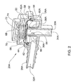
- FIG. 2 and 3A to 3C illustrating a valve designated 20A comprising a housing 26A fitted with an inlet tube section 28A and an outlet tube section 30A defining an inlet port 32A and an outlet port 34A respectively.
- a peripheral sealing wedge 52 of the diaphragm 50 is sealingly clamped between a peripheral annular groove 54 of housing 26A and a corresponding clamping portion 58 of cover 62A to thus retain the diaphragm 50 and provide sealing engagement such that a control chamber 66 extending above diaphragm 50 is not in flow communication with either the inlet chamber 36A or the outlet chamber 38A.
- the cover 62A comprises an aperture 68, illustrated in dashed lines, to air the control chamber 66 to the atmosphere.
- the diaphragm 50 is normally biased against the sealing ridge 44 by means of a coiled spring 72 bearing at one end against a portion of the cover 62A and at its opposed end against the diaphragm 50, the spring being axially retained by means of a support 74 extending from the cover 62A and a spring retaining projection 76 extending from the diaphragm 50.
- the cover 62A is typically snap-fitted over the housing 26A. though it may be otherwise attached, e.g. by adhering, heat or sonic welding, etc.
- a first valve controlled passage which is normally sealed by diaphragm 50 bearing against ridge 44 of the annular wall portion 42.
- a second valve controlled passage 84 extends between the inlet chamber 36A and the outlet chamber 38A and is normally sealed by a resilient sleeve member 86 which is self biased into sealing said aperture 84.
- section area ratio of the diaphragm 50 exposed to the outlet chamber 38 is substantially smaller than the section area exposed to the inlet chamber 36A (in the form of an annulus) thereby preventing the diaphragm 50 to displace into its open position upon substantially low pressurized fluid flow in the direction from the outlet chamber towards the inlet chamber but, on the other hand, will displace into the open position upon fluid flow in an opposite direction namely, from the inlet chamber 36A towards the outlet chamber 38A, upon a pressure differential which can overcome the nominal threshold of the biasing spring 72 and the elasticity of the diaphragm 50.
- Fig. 3A illustrates the valve 20A in a completely sealed position namely where the first valve controlled passage 80 is sealed by diaphragm 50 and where the second controlled passage 84 is sealed by the sleeve 86.
- this position there is substantially no flow between the inlet chamber 36A and the outlet chamber 38A namely no fluid flow between the fuel tank and the canister, both of which are not displayed.
- This position occurs at a substantially pressure equilibrium between the inlet chamber and the outlet chamber and in turn between the fuel tank and the vapor recovery device.
- a second position is illustrated in Fig. 3B referring to a position in which pressure rises within the fuel tank the consequence of which a corresponding rise in pressure occurs at the inlet chamber 36A resulting in the formation of the diaphragm 50 so as to disengage the annular rim 44 of the tubular wall 42, thus opening the first valve controlled passage 80 enabling fluid to flow towards the outlet chamber 38A.
- the cut-off pressure for displacing the diaphragm 50 into its open position is governed by the elasticity of the diaphragm 50 and by the biasing effect of spring 72.
- Fig. 3C there is illustrated a position where pressure at the vapor recovery device (i.e. canister) is higher than vapor pressure within the fuel tank as a result of which the resilient sleeve 86 is deformed to thereby expose the second valve controlled passage 84 allowing fluid flow in the direction from the outlet chamber 38A towards the inlet chamber 36A and into the fuel tank (not shown).
- the vapor recovery device i.e. canister
- the pressure threshold for displacing diaphragm 50 into its open position so as to expose the first valve controlled passage takes into account also the atmospheric pressure residing in the control chamber 66.
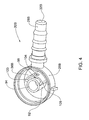
- a housing portion 26B which is basically similar to housing 26A disclosed in connection with Fig. 2 and comprises an inlet tube 28B defining an inlet port 32B connectable to the fuel tank by suitable tubing (not shown) and extending into an annular inlet chamber 36B.
- a tubular wall portion 92 is formed with a ridge 94 over which extends the first valve controlled passage, below the diaphragm (see Figs. 5A-5C ) and as already explained in connection with the previous example.
- a second valve controlled passage in the form of an aperture 98 is formed in the wall 92 similar to the arrangement disclosed in connection with the example of Figs. 2 and 3 with the provision of a shielding wall 100 also formed with an aperture 104 extending opposite the opening of the inlet tube 28B such that fluid flow there through has practically direct access into a space 108 formed between the shield portion 100 and the corresponding wall portion 92.
- a sealing member 112 in the form of a resilient leaf fixed at a bottom end thereof to the housing by means of stud 114 such that an upper portion of the seal member 112 is floppy and free to displace between a sealed position ( Figs. 5A and 5B ) and an open position ( Fig. 5C ).
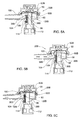
- Fig. 5A the control valve 20B is illustrated in a fully closed position namely with the first valve controlled passage 80B closed by diaphragm 50 and the second valve controlled passage 98 sealed by means of leave-like seal member 108.
- This position is understood to occur when the pressure at the inlet chamber 36B is lesser than the predetermined pressure threshold required for displacing the diaphragm 50 into its open position and also in a position where the pressure at the fuel tank and as a result at the inlet chamber 36B is higher than the pressure at the outlet chamber 38B.
- the first valve controlled passage 80B is opened to allow fluid flow from the fuel tank via the inlet chamber 36B and into the outlet chamber 38B from where it is free to flow to the fuel vapor recovery device. This position occurs upon pressure within the fuel tank namely, when a pressure build-up occurs within the fuel tank preceding the pressure threshold.
- the first valve controlled passage 80B is illustrated in its closed position whilst the second valve controlled passage 98 is open owing to displacement of the sealing leaf-like member 112 into its open position, i.e. disengaged from the tubular wall portion and bearing against the shield 100, thus allowing vapor flow from the outlet chamber 38B towards the inlet chamber 36B.
- This position occurs during generation of vacuum within the fuel tank e.g. upon consumption of fuel or in extreme cold locations where the volume of the fuel and fuel vapor within the tank reduce.
- the second valve controlled passage 98 remains closed under influence of fluid flow in the direction from the inlet port towards the outlet port owing to slight fluid pressure applied on the leaf-like sealing member 112 through the aperture 104 formed in the shield wall 100.
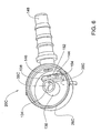
- FIG. 6 and 7A to 7C A further example is illustrated in Figs. 6 and 7A to 7C , illustrating a control valve generally designated 20C and which up to a great extent resembles the example illustrated in connection with Figs. 4 and 5A to 5C .
- the main differences residing between the present example and in the previous example resides in the configuration of the second valve controlled passage 134 formed in the annular wall portion 136 defining the outlet chamber 38C within the annular wall portion and the inlet chamber 36C outside the annular wall portion.
- the upper ridge 138 of the annular wall portion constitutes the seal for the diaphragm 140 ( Figs. 7A to 7C ) constituting therebetween the first valve controlled passage 80C.
- the second valve controlled passage 134 is in the form of a channel extending between the outlet chamber 38C and the inlet chamber 36C, terminating at the inlet chamber 36C at an inclined bed support 144 facing an outlet 146 of the inlet tube 148.
- the second valve controlled passage is sealable by means of a leaf-like sealing member 152 secured at one end thereof 154 to the housing 26C.
- the sealing member 152 is in its sealed position sealingly bearing over the bed 144 sealing the second valve controlled passage 134 whilst in Fig. 7C the sealing member 152 disengages from the bed 144 so as to allow fluid flow in the direction from the outlet chamber 38C towards the inlet chamber 36C.
- valve 20C is illustrated in its fully closed position namely with the first valve controlled passage 80C in the sealed position whereby diaphragm 140 sealingly bears over ridge 138 and where the second valve controlled passage is sealed by means of leaf-like sealing member 152 sealingly bearing over the inclined bed 144 and sealing the second valve controlled passage 134.
- first valve controlled passage 80C is open by means of displacement of diaphragm 140 to disengage from the ridge 138, thereby allowing fluid flow in the direction from the inlet chamber 36C towards the outlet chamber 38C whilst the second valve controlled passage 134 remains in its sealed position.
- FIG. 8 there is illustrated a modification of the second example referred to hereinabove resilient sealing leaf-like member 182.
- the valve generally designated 20D comprises a housing portion 26D which is basically similar to housing 26A disclosed in connection with Fig. 2 and comprises an inlet tube 28D defining an inlet port 32D connectable to the fuel tank by suitable tubing (not shown) and extending into an annular inlet chamber 36D.
- a tubular wall portion 154 is formed with a ridge 156 over which extends the first valve controlled passage 158, below the diaphragm 164.
- a second valve controlled passage in the form of an aperture 166 is formed in wall 168 below the tubular wall portion 154, similar to the arrangement disclosed in connection with the example of Figs.
- a shielding member 172 comprising a ring portion 174 for secure mounting over the tubular wall portion 154, and a shielding wall portion 178 extending opposite the aperture 166 and supporting a resilient sealing leaf-like member 182.
- the ring portion 174 is formed with an aperture 186 to allow fluid flow from aperture 166 towards the inlet chamber 36D.
- the shielding wall portion 174 is further formed with a protuberance 188 extending substantially opposite aperture 166, so as to support the resilient sealing leaf-like member 182 and prevent it from displacing. Operation of the valve disclosed in Fig. 8 is similar to that disclosed in connection with the previous examples, and in particular with respect to the example of Figs. 4 and 5 .
- a fuel vapor control valve may be fitted within a liquid fuel trap.
- vehicle fuel systems comprising a fuel vapor control valve fitted within a liquid fuel trap are described hereinafter with reference to Figs. 9A-10D .
- a valve generally designated 20E which has an similar internal construction to the valve 20D shown in Fig. 8 , at least with respect to the leaf-like member 182 ( Fig. 9D ) and first and second valve controlled passages.
- valve 20E is part of a vehicle fuel system generally designated 200 which further includes a liquid fuel trap 202, a fuel vapor recovery device 203 (only partially shown) and a pipe 22 for connecting the liquid fuel trap 202 to a fuel tank 12 (not shown).
- the liquid fuel trap generally designated as 202, comprises a body 207 formed with three cylindrical sections, including a first section 216A, a second section 216B, and a third section 216C extending therebetween.
- the first section 216A comprises a side wall 218A extending between a bottom wall 219A and a laterally extending wall 220A.
- the first section 216A also has a cross sectional diameter D1 .
- An expansion space 217 is defined between the side wall 218A, bottom wall 219A and laterally extending wall 220A.
- the bottom wall 219A is formed with an entry port 222 connectable to a pipe 22, for allowing flow communication between the liquid fuel trap 202 and the fuel tank 204 (not shown).
- the expansion space 217 is in flow communication with the entry port 222 of the liquid fuel trap 202.
- the third section 216C comprises a side wall 218C and has a cross sectional diameter D2 which is smaller than the cross sectional diameter D1 of the first section 216A.
- the laterally extending wall 220A extends between the side walls
- the third section 216C is formed with an exit port 226, formed in the side wall 218C, which allows flow communication between the valve 20E and an adjacent portion 227 of the refuel vapor recovery device 203.
- the fuel vapor recovery device 203 comprises an access port, generally designated as 229, in flow communication and integrally joined with the exit port, generally designated as 226, of the liquid fuel trap 202.
- the second section 216B comprises a top wall 219B, an annular wall 220B, and a side wall 218B extending therebetween.
- the second section 216B also has a cross sectional diameter D3, which is smaller than the cross sectional diameter D2 of the third section 216C.
- the annular wall 220B extends between the side walls (218B, 218C) of the second and third sections (216B, 216C).
- the second section 216B is formed with an additional port 228, formed in the top wall 219B, allowing flow communication between the valve 20E and an area 210, external to the fuel tank.
- the area 210 in this example being at atmospheric pressure.
- the annular wall 220A is formed with a fourth opening 230.
- the liquid fuel trap 202 further comprises an umbrella check valve 232 mounted on the fourth opening 230, and a dust cap 234 mounted above the umbrella check valve 232. This arrangement allows regulated flow communication between the first section 216A of the liquid fuel trap 202 and the area 210 external to the liquid fuel trap 202.
- valve 20E comprises three substantially cylindrical portions including a base housing portion 236, a top housing portion 238 and a central housing portion 26E extending therebetween.
- the valve 20E comprising first and second sealing arrangements (237, 239).
- the base housing portion 236 comprises an annular wall 240.
- the annular wall 240 has an outer diameter D4 corresponding in dimension to the cross sectional diameter D2 of the third section 216C of the liquid fuel trap 202.
- the annular wall 240 is formed with a peripheral groove 242 disposed near an upper edge 244 thereof, longitudinal slots 246 and a flexible snap lock member 248 (best seen in Figs. 9A-9C ) configured for connection to the fuel vapor recovery device.
- the base portion 236 further comprises an O-ring 250 mounted in the peripheral groove 242, both of which are disposed at an external portion of the base housing portion 236. Notably, the O-ring 250 engages and seals the side wall 218C in a gas-tight manner.
- first sealing arrangement 237 is constituted by the O-ring 250 and the peripheral groove 242 of the base housing portion 236 of the valve 20E, however it will be appreciated that, alternatively, a sealing arrangement having similar elements could also be part of the liquid fuel trap 202 and not the valve 20E.
- a lower edge 241 of the annular wall 240 of the base housing portion 236 defines an inlet port 32E of the valve 20E.
- the inlet port 32E is in flow communication with the expansion space 217.
- the inlet port 32E extends into an inlet chamber 36E of the valve 20E.
- the top housing portion 238 comprises a cylindrical section 252 and a convexly-shaped top section 254 extending from the cylindrical section 252.
- the cylindrical section 252 is formed with a peripheral groove 256 having a second O-ring 258 mounted therein, both of which are disposed at an external portion of the top housing portion 238.
- the O-ring 258 engages and seals the side wall 218B in a gas-tight manner.
- the convexly-shaped top section 254 is formed with an airing aperture 260 configured to allow flow communication between the valve 20E and the area 210 via the liquid fuel trap 202.
- the central housing portion 26E comprises an annular wall 261, a tubular wall portion 255 formed with a ridge 257 adjacent to which extends the first valve controlled passage 259, below the diaphragm 264.
- the annular wall 261 is formed with an outlet port 263, allowing flow communication between an outlet chamber 265 of the valve 20E, and the exit port 226 of the liquid fuel trap 202, and hence also with the access port 229 and the fuel vapor recovery device 203.
- the outlet port 263, is an aperture. It will be appreciated that previous examples of valves included a radially extending outlet tube section (for example, the tube section designated 30A in Fig. 2 ), however, as illustrated, a valve having a similar function may be free of such tube section.
- a valve free of a radially extending tube or element may allow ease of assembly of the valve within a portion of a liquid trap (in this example the cylindrical third section 216C).
- the outlet chamber 265 can be divided into a first sub-chamber 265A and an additional sub-chamber 265B of greater volume than the first sub-chamber 265A.
- a second valve controlled passage in the form of an aperture 266 is formed in wall 268 below the tubular wall portion 255, similar to the arrangement disclosed in connection with the example of Figs. 2 , 3 and 8 , with the provision of a shielding member 272.
- the second valve controlled passage 266 is configured to enable flow communication between the additional sub-chamber 265B and inlet chamber 36E, when the resilient sealing leaf-like member 282 is not in a sealing position.
- the shielding member 272 comprising a ring portion 274 for secure mounting over the tubular wall portion 255, and a shielding wall portion 278 extending opposite the aperture 266 and supporting a resilient sealing leaf-like member 282.
- the ring portion 274 is formed with an aperture (not shown) to allow flow through the aperture 266 towards the inlet chamber 36E.
- the shielding wall portion 274 is further formed with a protuberance 288 extending substantially opposite aperture 266, so as to support the resilient sealing leaf-like member 282 and prevent displacement thereof which would cause flow communication under conditions contrary to the desired function of the valve.
- valve 20E not only differs from previous examples in that it is free of a radially extending tube, i.e. it is substantially cylindrical, but also that the internal components thereof are configured in a different orientation.
- the inlet chamber 36E extends along a linear path from the inlet port 32E to the diaphragm 264.
- the diaphragm 264 has a face 264A configured to seal the first valve controlled passage 259, the face 264A extending along a plane parallel with the inlet port 32E.
- the airing aperture 260 is oriented in a direction parallel to the inlet port 32E.
- the airing aperture 260 is oriented in a direction perpendicular to the outlet port 263.
- the first O-ring 250 prevents flow communication between the expansion space 217 of the liquid fuel trap 202, and the outlet port 263 of the valve 20E, along a path external to the base housing portion 236.
- the second O-ring 258 prevents flow communication between the additional port 228 of the liquid fuel trap 202, and the outlet port 263 of the valve 20E, along a path external to the top housing portion 238 and central housing portion 26E.
- valve 20F which has a similar internal construction to the valve 20E shown in Figs. 9A-9D .
- the valve 20F comprises a base housing portion 336, a top housing portion 338 and a central housing portion 26F extending therebetween.
- Fig. 10D it can be seen that the valve 20F is part of a vehicle fuel system generally designated 300 which further includes a liquid fuel trap 302, a fuel vapor recovery device 303 (only partially shown) and a pipe 22 for connecting the liquid fuel trap 302 to a fuel tank 12 (not shown).
- the present example is similar to the vehicle fuel system 200 in the previous example, except that:
- valve 20F Operation of the valve 20F is similar to that disclosed in connection with the previous examples, with the additional function of the float 340 restricting flow through the central housing portion 26F when the valve rolls over.
- the float 340 since the diaphragm 364 is normally biased shut via an associated spring 366, the float 340 essentially acts as a back-up shut off mechanism.
- the second valve controlled passage may comprise more than one aperture.
Claims (15)
- Kraftstoffdampf-Steuerventil, das ein Gehäuse (26E, 236, 238) umfasst, wobei das Gehäuse Folgendes umfasst:Einlass- und Auslassöffnungen in Strömungsverbindung über erste und zweite ventilgesteuerte Durchlässe; wobei der erste ventilgesteuerte Durchlass konfiguriert ist, Kraftstoffdampfströmung in einer Richtung von der Einlassöffnung zu der Auslassöffnung nur dann zuzulassen, wenn Druck an der Einlassöffnung einen vorbestimmten Schwellenwert überschreitet; wobei der zweite ventilgesteuerte Durchlass konfiguriert ist, Kraftstoffdampfströmung in einer Richtung von der Auslassöffnung zu der Einlassöffnung nur dann zuzulassen, wenn Druck an der Einlassöffnung unter Druck an der Auslassöffnung fällt; wobei das Kraftstoffdampf-Steuerventil ferner eine Dichtungsanordnung (237) umfasst, dadurch gekennzeichnet, dass die Dichtungsanordnung (237) an einem äußeren Abschnitt des Gehäuses (236) zwischen den Einlass- und Auslassöffnungen angeordnet ist, wobei die Dichtungsanordnung für abdichtenden Eingriff zwischen dem Kraftstoffdampf-Steuerventil (20E) und einer äußeren Komponente (202) davon, über direkten Kontakt mit der Komponente, konfiguriert ist.
- Kraftstoffdampf-Steuerventil nach Anspruch 1, wobei die Dichtungsanordnung (237) ferner ein Dichtelement umfasst, wobei das Dichtelement ein O-Ring (250) oder eine umlaufende Nut (242) ist, die in dem Gehäuse des Kraftstoffdampf-Steuerventils gebildet ist.
- Kraftstoffdampf-Steuerventil nach einem der Ansprüche 1 bis 2, wobei das Kraftstoffdampf-Steuerventil ferner eine Einlasskammer umfasst, die mit der Einlassöffnung assoziiert ist, eine Auslasskammer, die mit der Auslassöffnung assoziiert ist, und eine Steuerkammer, die zwischen der Einlass- und Auslasskammer angeordnet ist, umfasst; wobei das Gehäuse mit einer Entlüftungsöffnung (260) gebildet ist, die mit der Steuerkammer assoziiert ist.
- Kraftstoffdampf-Steuerventil nach Anspruch 3, wobei das Kraftstoffdampf-Steuerventil mindestens eine zusätzliche Dichtungsanordnung (239) umfasst.
- Kraftstoffdampf-Steuerventil nach Anspruch 4, wobei die mindestens eine zusätzliche Dichtungsanordnung (239) an einem äußeren Teil des Gehäuses (238) zwischen der Entlüftungsöffnung und der Einlassöffnung angeordnet ist oder an einem äußeren Teil des Gehäuses zwischen der Entlüftungsöffnung und der Auslassöffnung angeordnet ist.
- Kraftstoffdampf-Steuerventil nach einem der Ansprüche 1 bis 5, das konfiguriert ist, um einen Fluss von der Einlassöffnung zu der Auslassöffnung zu verhindern, wenn der Druck an der Auslassöffnung unter den Druck an der Einlassöffnung fällt.
- Fahrzeugkraftstoffsystem, das einen Flüssigkraftstoffabscheider (202) und ein Kraftstoffdampf-Steuerventil (20E) umfasst; wobei der Flüssigkraftstoffabscheider einen Körper (216A, 216B, 216C) umfasst, der mit einem Expansionsraum gebildet ist; das Kraftstoffdampf-Steuerventil ein Gehäuse (26E, 236, 238) umfasst, das Einlass- und Auslassöffnungen aufweist, die in Strömungsverbindung mit dem Expansionsraum des Flüssigkraftstoffabscheiders sind; dadurch gekennzeichnet, dass eine Dichtungsanordnung (237) zwischen dem Flüssigkraftstoffabscheider (202) und dem Kraftstoffdampf-Steuerventil (20E) angeordnet ist; die Dichtungsanordnung (237) an einem äußeren Teil des Gehäuses (236) des Kraftstoffdampf-Steuerventils und zwischen den Einlass- und Auslassöffnungen davon angeordnet ist; wobei die Dichtungsanordnung (237) konfiguriert ist, Strömungsverbindung durch einen Bereich, der zwischen dem Körper des Flüssigkraftstoffabscheiders und dem Gehäuse des Kraftstoffdampf-Steuerventils angeordnet ist, zu verhindern.
- Fahrzeugkraftstoffsystem nach Anspruch 7, wobei die Dichtungsanordnung konfiguriert ist, eine Strömungsverbindung durch einen Bereich, der zwischen Eintritts- und Austrittsöffnungen des Flüssigkraftstoffabscheiders und außerhalb des Gehäuses des Kraftstoffdampf-Steuerventils angeordnet ist, zu verhindern.
- Fahrzeugkraftstoffsystem nach Anspruch 7 oder 8, wobei die Dichtungsanordnung zum abdichtenden Eingriff durch einen Eingriff von gegenüberliegenden Oberflächen des Körpers des Flüssigkraftstoffabscheiders und des Gehäuses des Kraftstoffdampf-Steuerventils konfiguriert ist.
- Fahrzeugkraftstoffsystem nach einem der Ansprüche 7 bis 9, wobei das Kraftstoffdampf-Steuerventil (20E) ferner eine Entlüftungsöffnung (260) umfasst und der Flüssigkraftstoffabscheider (202) ferner eine zusätzliche Öffnung (228) umfasst und das Fahrzeugkraftstoffsystem ferner mindestens eine zusätzliche Dichtungsanordnung (239, 258) umfasst, die konfiguriert ist, eine Strömungsverbindung durch einen Bereich, der außerhalb des Gehäuses des Ventils ist, und zwischen der zusätzlichen Öffnung (228) und Austrittsöffnung (226) des Flüssigkraftstoffabscheiders (202) zu verhindern, und konfiguriert ist, eine Strömungsverbindung zwischen der Entlüftungsöffnung (260) und der Auslassöffnung des Kraftstoffdampf-Steuerventils (20E) entlang eines Wegs, der außerhalb des Gehäuses des Kraftstoffdampf-Steuerventils ist, zu verhindern.
- Fahrzeugkraftstoffsystem nach einem der Ansprüche 7 bis 10, wobei das Fahrzeugkraftstoffsystem ferner eine Kraftstoffdampf-Rückgewinnungsvorrichtung (203) umfasst, die eine Zutrittsöffnung (229) in Strömungsverbindung mit einer Austrittsöffnung (226) des Flüssigkraftstoffabscheiders (202) umfasst und die Austrittsöffnung des Flüssigkraftstoffabscheiders und die Zutrittsöffnung der Kraftstoffdampf-Rückgewinnungsvorrichtung stoffschlüssig verbunden sind.
- Fahrzeugkraftstoffsystem nach einem der Ansprüche 7 bis 11, wobei das Fahrzeugkraftstoffsystem ferner eine Kraftstoffdampf-Rückgewinnungsvorrichtung, die eine Zutrittsöffnung in Strömungsverbindung mit einer Austrittsöffnung des Flüssigkraftstoffabscheiders und einen Kanal umfasst, über den die Austrittsöffnung des Flüssigkraftstoffabscheiders und Zutrittsöffnung der Kraftstoffdampf-Rückgewinnungsvorrichtung verbunden sind.
- Fahrzeugkraftstoffsystem nach einem der Ansprüche 7 bis 12, wobei der Körper des Flüssigkraftstoffabscheiders ferner mit einem Abschnitt gebildet ist, der eine innere Querschnittsform aufweist, die einer äußeren Querschnittsform des Kraftstoffdampf-Steuerventils entspricht, wodurch dem Kraftstoffdampf-Steuerventil ermöglicht wird, in einer gasdichten Weise innerhalb des Abschnitts des Flüssigkraftstoffabscheiders eingepasst zu werden.
- Fahrzeugkraftstoffsystem, das einen Flüssigkraftstoffabscheider (202), der mit einem Expansionsraum gebildet ist, und ein Ventil (20E) umfasst; wobei das Ventil ein Gehäuse (26E, 236, 238) umfasst, das mit Einlass- und Auslassöffnungen in Strömungsverbindung über mindestens einen inneren Durchlass in dem Gehäuse gebildet ist; wobei die Einlassöffnung des Ventils in Strömungsverbindung mit dem Expansionsraum des Flüssigkraftstoffabscheiders (202) ist; dadurch gekennzeichnet, dass das Ventil (20E) in einer gasdichten Weise innerhalb des Flüssigkraftstoffabscheiders (202) eingepasst ist, wodurch eine Strömungsverbindung zwischen den Einlass- und Auslassöffnungen des Ventils entlang eines Wegs, der außerhalb des Ventils ist, verhindert wird.
- Fahrzeugkraftstoffsystem nach Anspruch 14, wobei der Flüssigkraftstoffabscheider ferner mit einem Abschnitt gebildet ist, der eine innere Querschnittsform aufweist, die einer äußeren Querschnittsform des Ventils entspricht, wodurch dem Ventil ermöglicht wird, in einer gasdichten Weise innerhalb des Abschnitts des Flüssigkraftstoffabscheiders eingepasst zu werden.
Applications Claiming Priority (2)
| Application Number | Priority Date | Filing Date | Title |
|---|---|---|---|
| US12/628,488 US8950382B2 (en) | 2004-12-16 | 2009-12-01 | Vehicle fuel system and components thereof |
| PCT/IL2010/000994 WO2011067753A2 (en) | 2009-12-01 | 2010-11-29 | Vehicle fuel system and components thereof |
Publications (2)
| Publication Number | Publication Date |
|---|---|
| EP2507086A2 EP2507086A2 (de) | 2012-10-10 |
| EP2507086B1 true EP2507086B1 (de) | 2016-11-16 |
Family
ID=44115370
Family Applications (1)
| Application Number | Title | Priority Date | Filing Date |
|---|---|---|---|
| EP10799125.9A Active EP2507086B1 (de) | 2009-12-01 | 2010-11-29 | Kraftstoffsystem für fahrzeug und komponenten davon |
Country Status (8)
| Country | Link |
|---|---|
| US (1) | US8950382B2 (de) |
| EP (1) | EP2507086B1 (de) |
| JP (1) | JP5810093B2 (de) |
| KR (1) | KR101733827B1 (de) |
| CN (1) | CN102712250B (de) |
| BR (1) | BR112012013129B1 (de) |
| RU (1) | RU2550413C2 (de) |
| WO (1) | WO2011067753A2 (de) |
Families Citing this family (9)
| Publication number | Priority date | Publication date | Assignee | Title |
|---|---|---|---|---|
| WO2012174347A1 (en) * | 2011-06-16 | 2012-12-20 | Continental Automotive Systems, Inc. | Canister purge valve with modular lower body having integeral check valves |
| US9127605B2 (en) * | 2012-03-21 | 2015-09-08 | Ford Global Technologies, Llc | Vapor recovery system purge valve and method |
| AU2014265020B2 (en) * | 2013-12-13 | 2019-01-31 | Ford Global Technologies,Llc | Method and System for Improved Vent |
| EP3172075B1 (de) * | 2014-07-21 | 2021-04-21 | Bayerische Motoren Werke Aktiengesellschaft | Tanksystem eines kraftfahrzeugs mit einem volumenveränderungselement |
| CN106574591B (zh) * | 2014-08-15 | 2018-12-28 | 瓦锡兰芬兰有限公司 | 用于内燃发动机的燃料喷射阀装置 |
| FR3054609A1 (fr) * | 2016-07-29 | 2018-02-02 | Plastic Omnium Advanced Innovation & Res | Regulateur de debit de ventilation pour un reservoir pressurise de vehicule. |
| US10377229B2 (en) * | 2017-05-11 | 2019-08-13 | GM Global Technology Operations LLC | Fuel storage assembly for a vehicle |
| WO2018224577A1 (en) * | 2017-06-09 | 2018-12-13 | Plastic Omnium Advanced Innovation And Research | Vehicle fuel system with vapour control |
| FR3069811B1 (fr) | 2017-08-02 | 2019-08-02 | Sogefi Filtration | Dispositif de regulation de pression et son procede d'assemblage, pour un absorbeur de vapeurs de carburant |
Family Cites Families (31)
| Publication number | Priority date | Publication date | Assignee | Title |
|---|---|---|---|---|
| US2782777A (en) * | 1953-09-01 | 1957-02-26 | Elmer P Jasper | Internal combustion engines |
| US2821429A (en) * | 1956-09-19 | 1958-01-28 | Gen Motors Corp | Vehicle body drainage and sealing means |
| US3616783A (en) * | 1970-03-06 | 1971-11-02 | Borg Warner | Vapor control valve |
| US4337873A (en) * | 1980-11-17 | 1982-07-06 | General Motors Corporation | Fuel cap with poppet type valves |
| JPH07132740A (ja) * | 1993-11-05 | 1995-05-23 | Toyoda Gosei Co Ltd | 燃料蒸気処理装置 |
| US5666989A (en) * | 1994-11-08 | 1997-09-16 | Stant Manufacturing Inc. | Tank venting control assembly |
| JP2920226B2 (ja) * | 1994-12-28 | 1999-07-19 | 本田技研工業株式会社 | 蒸発燃料放出抑制装置 |
| JPH0932670A (ja) * | 1995-07-25 | 1997-02-04 | Honda Motor Co Ltd | 蒸発燃料制御弁 |
| JPH09296755A (ja) * | 1996-05-07 | 1997-11-18 | Honda Motor Co Ltd | キャニスタの吸排気構造 |
| US6003499A (en) * | 1998-01-07 | 1999-12-21 | Stant Manufacturing Inc. | Tank vent control apparatus |
| DE19824791A1 (de) * | 1998-06-03 | 1999-12-16 | Kayser Automotive Systems Gmbh | Tankschutzventil |
| IL128937A (en) * | 1999-03-11 | 2002-09-12 | Raval Agriculture Coop Soc Ltd | Multi-purpose valve |
| US6708713B1 (en) * | 1999-04-16 | 2004-03-23 | Tesma International Inc. | Fill limit control valve assembly having a liquid fuel trap |
| JP3678088B2 (ja) * | 1999-11-26 | 2005-08-03 | 日産自動車株式会社 | 蒸発燃料処理装置 |
| JP3558573B2 (ja) * | 1999-12-21 | 2004-08-25 | トヨタ自動車株式会社 | 蒸発燃料排出抑制装置 |
| IL134535A0 (en) * | 2000-02-14 | 2001-04-30 | Raviv Prec Injection Molding | Improved filling valve |
| IL137529A0 (en) | 2000-07-26 | 2001-07-24 | Raviv Prec Injection Molding | Vapor recovery control valve |
| US6786227B2 (en) * | 2000-08-17 | 2004-09-07 | Siemens Automotive Inc. | System and method including a fuel tank isolation valve |
| US6364145B1 (en) * | 2000-08-21 | 2002-04-02 | Richard J. Shaw | Motor vehicle fuel cap inlet and outlet vent apparatus |
| US6557581B2 (en) * | 2001-03-01 | 2003-05-06 | Raviv Precision Injection Molding | Liquid fuel trap |
| KR100400517B1 (ko) * | 2001-04-28 | 2003-10-08 | 삼성광주전자 주식회사 | 왕복동식 압축기의 밸브어셈블리 |
| JP4042047B2 (ja) * | 2003-02-20 | 2008-02-06 | 京三電機株式会社 | 蒸発燃料処理装置 |
| US20040194831A1 (en) * | 2003-04-01 | 2004-10-07 | Balsdon David W. | System and method including a fluid actuated fuel tank isolation valve |
| EP1488947A3 (de) | 2003-06-16 | 2005-06-15 | Stant Manufacturing Inc. | Belüftungssystem für Kraftstofftank mit Filter für Flüssigbrennstoff |
| US7047997B2 (en) * | 2003-07-29 | 2006-05-23 | Delphi Technologies, Inc. | Fuel tank vent valve |
| US6966330B2 (en) * | 2003-08-27 | 2005-11-22 | Alfmeier Corporation | Weldring with locking arrangement for valve assembly |
| US6918405B2 (en) * | 2003-12-04 | 2005-07-19 | Alfmeier Corporation | Fill limit vent valve |
| US7207347B2 (en) * | 2004-08-23 | 2007-04-24 | Raval A.S.C. Ltd. | Dual function valve for fuel tank |
| IL165845A0 (en) * | 2004-12-16 | 2006-01-15 | Raval Acs Ltd | Vapor recovery control valve |
| US8286658B2 (en) * | 2005-06-07 | 2012-10-16 | Stant Usa Corp. | Roll-over valve with shared overfill protection and vacuum relief |
| DE102010055320A1 (de) | 2010-12-21 | 2012-06-21 | Audi Ag | Kraftstoffsystem |
-
2009
- 2009-12-01 US US12/628,488 patent/US8950382B2/en active Active
-
2010
- 2010-11-29 KR KR1020127016942A patent/KR101733827B1/ko not_active Application Discontinuation
- 2010-11-29 CN CN201080061068.0A patent/CN102712250B/zh active Active
- 2010-11-29 BR BR112012013129-0A patent/BR112012013129B1/pt active IP Right Grant
- 2010-11-29 RU RU2012126376/11A patent/RU2550413C2/ru active
- 2010-11-29 EP EP10799125.9A patent/EP2507086B1/de active Active
- 2010-11-29 WO PCT/IL2010/000994 patent/WO2011067753A2/en active Application Filing
- 2010-11-29 JP JP2012541622A patent/JP5810093B2/ja active Active
Also Published As
| Publication number | Publication date |
|---|---|
| JP5810093B2 (ja) | 2015-11-11 |
| BR112012013129B1 (pt) | 2021-09-08 |
| WO2011067753A2 (en) | 2011-06-09 |
| EP2507086A2 (de) | 2012-10-10 |
| US20100139625A1 (en) | 2010-06-10 |
| CN102712250A (zh) | 2012-10-03 |
| KR20120112501A (ko) | 2012-10-11 |
| KR101733827B1 (ko) | 2017-05-08 |
| BR112012013129A2 (pt) | 2020-08-18 |
| RU2012126376A (ru) | 2014-01-10 |
| US8950382B2 (en) | 2015-02-10 |
| JP2013512390A (ja) | 2013-04-11 |
| CN102712250B (zh) | 2015-09-09 |
| WO2011067753A3 (en) | 2011-10-13 |
| RU2550413C2 (ru) | 2015-05-10 |
Similar Documents
| Publication | Publication Date | Title |
|---|---|---|
| EP2507086B1 (de) | Kraftstoffsystem für fahrzeug und komponenten davon | |
| EP1831049B1 (de) | Dampfrückgewinnungssteuerventil | |
| US8109285B2 (en) | Roll over vent valve | |
| EP2016320B1 (de) | Kraftstoffentlüftungsventil und verbesserung davon | |
| US5234013A (en) | Tank venting control assembly | |
| US7717092B2 (en) | Fuel system with air venting and fuel anti-drainback | |
| US6561211B2 (en) | Fuel tank vent control valve | |
| US8376180B2 (en) | Venting tubing system for a fuel tank | |
| WO2002008597A1 (en) | Valve for controlling the fuel vapor pressure in a tank system | |
| JPH0960740A (ja) | ダイアフラム弁 |
Legal Events
| Date | Code | Title | Description |
|---|---|---|---|
| PUAI | Public reference made under article 153(3) epc to a published international application that has entered the european phase |
Free format text: ORIGINAL CODE: 0009012 |
|
| 17P | Request for examination filed |
Effective date: 20120629 |
|
| AK | Designated contracting states |
Kind code of ref document: A2 Designated state(s): AL AT BE BG CH CY CZ DE DK EE ES FI FR GB GR HR HU IE IS IT LI LT LU LV MC MK MT NL NO PL PT RO RS SE SI SK SM TR |
|
| DAX | Request for extension of the european patent (deleted) | ||
| RIC1 | Information provided on ipc code assigned before grant |
Ipc: F16K 24/00 20060101ALI20160419BHEP Ipc: B60K 15/035 20060101AFI20160419BHEP Ipc: F02M 25/08 20060101ALI20160419BHEP Ipc: B60K 15/03 20060101ALI20160419BHEP Ipc: F16K 17/196 20060101ALI20160419BHEP |
|
| GRAP | Despatch of communication of intention to grant a patent |
Free format text: ORIGINAL CODE: EPIDOSNIGR1 |
|
| INTG | Intention to grant announced |
Effective date: 20160603 |
|
| GRAS | Grant fee paid |
Free format text: ORIGINAL CODE: EPIDOSNIGR3 |
|
| GRAA | (expected) grant |
Free format text: ORIGINAL CODE: 0009210 |
|
| AK | Designated contracting states |
Kind code of ref document: B1 Designated state(s): AL AT BE BG CH CY CZ DE DK EE ES FI FR GB GR HR HU IE IS IT LI LT LU LV MC MK MT NL NO PL PT RO RS SE SI SK SM TR |
|
| REG | Reference to a national code |
Ref country code: GB Ref legal event code: FG4D |
|
| REG | Reference to a national code |
Ref country code: CH Ref legal event code: EP |
|
| REG | Reference to a national code |
Ref country code: IE Ref legal event code: FG4D |
|
| REG | Reference to a national code |
Ref country code: AT Ref legal event code: REF Ref document number: 845549 Country of ref document: AT Kind code of ref document: T Effective date: 20161215 |
|
| REG | Reference to a national code |
Ref country code: FR Ref legal event code: PLFP Year of fee payment: 7 |
|
| REG | Reference to a national code |
Ref country code: DE Ref legal event code: R096 Ref document number: 602010038095 Country of ref document: DE |
|
| REG | Reference to a national code |
Ref country code: DE Ref legal event code: R096 Ref document number: 602010038095 Country of ref document: DE |
|
| PG25 | Lapsed in a contracting state [announced via postgrant information from national office to epo] |
Ref country code: LV Free format text: LAPSE BECAUSE OF FAILURE TO SUBMIT A TRANSLATION OF THE DESCRIPTION OR TO PAY THE FEE WITHIN THE PRESCRIBED TIME-LIMIT Effective date: 20161116 |
|
| REG | Reference to a national code |
Ref country code: NL Ref legal event code: MP Effective date: 20161116 |
|
| REG | Reference to a national code |
Ref country code: LT Ref legal event code: MG4D |
|
| REG | Reference to a national code |
Ref country code: AT Ref legal event code: MK05 Ref document number: 845549 Country of ref document: AT Kind code of ref document: T Effective date: 20161116 |
|
| PG25 | Lapsed in a contracting state [announced via postgrant information from national office to epo] |
Ref country code: NL Free format text: LAPSE BECAUSE OF FAILURE TO SUBMIT A TRANSLATION OF THE DESCRIPTION OR TO PAY THE FEE WITHIN THE PRESCRIBED TIME-LIMIT Effective date: 20161116 Ref country code: NO Free format text: LAPSE BECAUSE OF FAILURE TO SUBMIT A TRANSLATION OF THE DESCRIPTION OR TO PAY THE FEE WITHIN THE PRESCRIBED TIME-LIMIT Effective date: 20170216 Ref country code: LT Free format text: LAPSE BECAUSE OF FAILURE TO SUBMIT A TRANSLATION OF THE DESCRIPTION OR TO PAY THE FEE WITHIN THE PRESCRIBED TIME-LIMIT Effective date: 20161116 Ref country code: GR Free format text: LAPSE BECAUSE OF FAILURE TO SUBMIT A TRANSLATION OF THE DESCRIPTION OR TO PAY THE FEE WITHIN THE PRESCRIBED TIME-LIMIT Effective date: 20170217 Ref country code: SE Free format text: LAPSE BECAUSE OF FAILURE TO SUBMIT A TRANSLATION OF THE DESCRIPTION OR TO PAY THE FEE WITHIN THE PRESCRIBED TIME-LIMIT Effective date: 20161116 |
|
| PG25 | Lapsed in a contracting state [announced via postgrant information from national office to epo] |
Ref country code: FI Free format text: LAPSE BECAUSE OF FAILURE TO SUBMIT A TRANSLATION OF THE DESCRIPTION OR TO PAY THE FEE WITHIN THE PRESCRIBED TIME-LIMIT Effective date: 20161116 Ref country code: AT Free format text: LAPSE BECAUSE OF FAILURE TO SUBMIT A TRANSLATION OF THE DESCRIPTION OR TO PAY THE FEE WITHIN THE PRESCRIBED TIME-LIMIT Effective date: 20161116 Ref country code: HR Free format text: LAPSE BECAUSE OF FAILURE TO SUBMIT A TRANSLATION OF THE DESCRIPTION OR TO PAY THE FEE WITHIN THE PRESCRIBED TIME-LIMIT Effective date: 20161116 Ref country code: RS Free format text: LAPSE BECAUSE OF FAILURE TO SUBMIT A TRANSLATION OF THE DESCRIPTION OR TO PAY THE FEE WITHIN THE PRESCRIBED TIME-LIMIT Effective date: 20161116 Ref country code: ES Free format text: LAPSE BECAUSE OF FAILURE TO SUBMIT A TRANSLATION OF THE DESCRIPTION OR TO PAY THE FEE WITHIN THE PRESCRIBED TIME-LIMIT Effective date: 20161116 Ref country code: PL Free format text: LAPSE BECAUSE OF FAILURE TO SUBMIT A TRANSLATION OF THE DESCRIPTION OR TO PAY THE FEE WITHIN THE PRESCRIBED TIME-LIMIT Effective date: 20161116 Ref country code: BE Free format text: LAPSE BECAUSE OF NON-PAYMENT OF DUE FEES Effective date: 20161130 Ref country code: PT Free format text: LAPSE BECAUSE OF FAILURE TO SUBMIT A TRANSLATION OF THE DESCRIPTION OR TO PAY THE FEE WITHIN THE PRESCRIBED TIME-LIMIT Effective date: 20170316 |
|
| REG | Reference to a national code |
Ref country code: CH Ref legal event code: PL |
|
| PG25 | Lapsed in a contracting state [announced via postgrant information from national office to epo] |
Ref country code: CH Free format text: LAPSE BECAUSE OF NON-PAYMENT OF DUE FEES Effective date: 20161130 Ref country code: CZ Free format text: LAPSE BECAUSE OF FAILURE TO SUBMIT A TRANSLATION OF THE DESCRIPTION OR TO PAY THE FEE WITHIN THE PRESCRIBED TIME-LIMIT Effective date: 20161116 Ref country code: LI Free format text: LAPSE BECAUSE OF NON-PAYMENT OF DUE FEES Effective date: 20161130 Ref country code: DK Free format text: LAPSE BECAUSE OF FAILURE TO SUBMIT A TRANSLATION OF THE DESCRIPTION OR TO PAY THE FEE WITHIN THE PRESCRIBED TIME-LIMIT Effective date: 20161116 Ref country code: SK Free format text: LAPSE BECAUSE OF FAILURE TO SUBMIT A TRANSLATION OF THE DESCRIPTION OR TO PAY THE FEE WITHIN THE PRESCRIBED TIME-LIMIT Effective date: 20161116 Ref country code: EE Free format text: LAPSE BECAUSE OF FAILURE TO SUBMIT A TRANSLATION OF THE DESCRIPTION OR TO PAY THE FEE WITHIN THE PRESCRIBED TIME-LIMIT Effective date: 20161116 Ref country code: RO Free format text: LAPSE BECAUSE OF FAILURE TO SUBMIT A TRANSLATION OF THE DESCRIPTION OR TO PAY THE FEE WITHIN THE PRESCRIBED TIME-LIMIT Effective date: 20161116 |
|
| REG | Reference to a national code |
Ref country code: DE Ref legal event code: R097 Ref document number: 602010038095 Country of ref document: DE |
|
| REG | Reference to a national code |
Ref country code: IE Ref legal event code: MM4A |
|
| PG25 | Lapsed in a contracting state [announced via postgrant information from national office to epo] |
Ref country code: BG Free format text: LAPSE BECAUSE OF FAILURE TO SUBMIT A TRANSLATION OF THE DESCRIPTION OR TO PAY THE FEE WITHIN THE PRESCRIBED TIME-LIMIT Effective date: 20170216 Ref country code: BE Free format text: LAPSE BECAUSE OF FAILURE TO SUBMIT A TRANSLATION OF THE DESCRIPTION OR TO PAY THE FEE WITHIN THE PRESCRIBED TIME-LIMIT Effective date: 20161116 Ref country code: IT Free format text: LAPSE BECAUSE OF FAILURE TO SUBMIT A TRANSLATION OF THE DESCRIPTION OR TO PAY THE FEE WITHIN THE PRESCRIBED TIME-LIMIT Effective date: 20161116 Ref country code: SM Free format text: LAPSE BECAUSE OF FAILURE TO SUBMIT A TRANSLATION OF THE DESCRIPTION OR TO PAY THE FEE WITHIN THE PRESCRIBED TIME-LIMIT Effective date: 20161116 |
|
| PLBE | No opposition filed within time limit |
Free format text: ORIGINAL CODE: 0009261 |
|
| STAA | Information on the status of an ep patent application or granted ep patent |
Free format text: STATUS: NO OPPOSITION FILED WITHIN TIME LIMIT |
|
| PG25 | Lapsed in a contracting state [announced via postgrant information from national office to epo] |
Ref country code: LU Free format text: LAPSE BECAUSE OF NON-PAYMENT OF DUE FEES Effective date: 20161130 Ref country code: MC Free format text: LAPSE BECAUSE OF FAILURE TO SUBMIT A TRANSLATION OF THE DESCRIPTION OR TO PAY THE FEE WITHIN THE PRESCRIBED TIME-LIMIT Effective date: 20161116 |
|
| 26N | No opposition filed |
Effective date: 20170817 |
|
| REG | Reference to a national code |
Ref country code: FR Ref legal event code: PLFP Year of fee payment: 8 |
|
| PG25 | Lapsed in a contracting state [announced via postgrant information from national office to epo] |
Ref country code: IE Free format text: LAPSE BECAUSE OF NON-PAYMENT OF DUE FEES Effective date: 20161129 Ref country code: SI Free format text: LAPSE BECAUSE OF FAILURE TO SUBMIT A TRANSLATION OF THE DESCRIPTION OR TO PAY THE FEE WITHIN THE PRESCRIBED TIME-LIMIT Effective date: 20161116 |
|
| PG25 | Lapsed in a contracting state [announced via postgrant information from national office to epo] |
Ref country code: HU Free format text: LAPSE BECAUSE OF FAILURE TO SUBMIT A TRANSLATION OF THE DESCRIPTION OR TO PAY THE FEE WITHIN THE PRESCRIBED TIME-LIMIT; INVALID AB INITIO Effective date: 20101129 Ref country code: CY Free format text: LAPSE BECAUSE OF FAILURE TO SUBMIT A TRANSLATION OF THE DESCRIPTION OR TO PAY THE FEE WITHIN THE PRESCRIBED TIME-LIMIT Effective date: 20161116 |
|
| PG25 | Lapsed in a contracting state [announced via postgrant information from national office to epo] |
Ref country code: MK Free format text: LAPSE BECAUSE OF FAILURE TO SUBMIT A TRANSLATION OF THE DESCRIPTION OR TO PAY THE FEE WITHIN THE PRESCRIBED TIME-LIMIT Effective date: 20161116 Ref country code: TR Free format text: LAPSE BECAUSE OF FAILURE TO SUBMIT A TRANSLATION OF THE DESCRIPTION OR TO PAY THE FEE WITHIN THE PRESCRIBED TIME-LIMIT Effective date: 20161116 Ref country code: IS Free format text: LAPSE BECAUSE OF FAILURE TO SUBMIT A TRANSLATION OF THE DESCRIPTION OR TO PAY THE FEE WITHIN THE PRESCRIBED TIME-LIMIT Effective date: 20161116 |
|
| PG25 | Lapsed in a contracting state [announced via postgrant information from national office to epo] |
Ref country code: MT Free format text: LAPSE BECAUSE OF NON-PAYMENT OF DUE FEES Effective date: 20161129 |
|
| PG25 | Lapsed in a contracting state [announced via postgrant information from national office to epo] |
Ref country code: AL Free format text: LAPSE BECAUSE OF FAILURE TO SUBMIT A TRANSLATION OF THE DESCRIPTION OR TO PAY THE FEE WITHIN THE PRESCRIBED TIME-LIMIT Effective date: 20161116 |
|
| PGFP | Annual fee paid to national office [announced via postgrant information from national office to epo] |
Ref country code: FR Payment date: 20230929 Year of fee payment: 14 |
|
| PGFP | Annual fee paid to national office [announced via postgrant information from national office to epo] |
Ref country code: GB Payment date: 20231006 Year of fee payment: 14 |
|
| PGFP | Annual fee paid to national office [announced via postgrant information from national office to epo] |
Ref country code: DE Payment date: 20231003 Year of fee payment: 14 |