EP2507040B1 - Verfahren zur herstellung einer verbindungsstrebe aus einem verbundstoff mit einer verstärkten gabel - Google Patents
Verfahren zur herstellung einer verbindungsstrebe aus einem verbundstoff mit einer verstärkten gabel Download PDFInfo
- Publication number
- EP2507040B1 EP2507040B1 EP10787689.8A EP10787689A EP2507040B1 EP 2507040 B1 EP2507040 B1 EP 2507040B1 EP 10787689 A EP10787689 A EP 10787689A EP 2507040 B1 EP2507040 B1 EP 2507040B1
- Authority
- EP
- European Patent Office
- Prior art keywords
- layers
- yoke
- mandrel
- base
- connecting rod
- Prior art date
- Legal status (The legal status is an assumption and is not a legal conclusion. Google has not performed a legal analysis and makes no representation as to the accuracy of the status listed.)
- Active
Links
- 238000000034 method Methods 0.000 title claims description 21
- 239000002131 composite material Substances 0.000 title claims description 7
- 239000012783 reinforcing fiber Substances 0.000 claims description 31
- 239000000835 fiber Substances 0.000 claims description 17
- 239000011347 resin Substances 0.000 claims description 15
- 229920005989 resin Polymers 0.000 claims description 15
- 125000006850 spacer group Chemical group 0.000 claims description 12
- 238000004519 manufacturing process Methods 0.000 claims description 6
- 239000000463 material Substances 0.000 claims description 6
- 230000000379 polymerizing effect Effects 0.000 claims description 2
- 239000010410 layer Substances 0.000 description 76
- 239000004744 fabric Substances 0.000 description 14
- 208000027418 Wounds and injury Diseases 0.000 description 8
- 229920000049 Carbon (fiber) Polymers 0.000 description 6
- 239000004917 carbon fiber Substances 0.000 description 6
- 238000003780 insertion Methods 0.000 description 5
- 230000037431 insertion Effects 0.000 description 5
- 238000004804 winding Methods 0.000 description 5
- 238000009434 installation Methods 0.000 description 4
- 239000011229 interlayer Substances 0.000 description 4
- OKTJSMMVPCPJKN-UHFFFAOYSA-N Carbon Chemical compound [C] OKTJSMMVPCPJKN-UHFFFAOYSA-N 0.000 description 3
- 229910052799 carbon Inorganic materials 0.000 description 3
- 238000002347 injection Methods 0.000 description 3
- 239000007924 injection Substances 0.000 description 3
- 230000003014 reinforcing effect Effects 0.000 description 3
- KWGRBVOPPLSCSI-WPRPVWTQSA-N (-)-ephedrine Chemical compound CN[C@@H](C)[C@H](O)C1=CC=CC=C1 KWGRBVOPPLSCSI-WPRPVWTQSA-N 0.000 description 2
- 238000009954 braiding Methods 0.000 description 2
- 230000032798 delamination Effects 0.000 description 2
- 230000008021 deposition Effects 0.000 description 2
- 239000002184 metal Substances 0.000 description 2
- VNWKTOKETHGBQD-UHFFFAOYSA-N methane Chemical compound C VNWKTOKETHGBQD-UHFFFAOYSA-N 0.000 description 2
- 239000000243 solution Substances 0.000 description 2
- 206010013647 Drowning Diseases 0.000 description 1
- 239000004743 Polypropylene Substances 0.000 description 1
- 239000004793 Polystyrene Substances 0.000 description 1
- 230000006835 compression Effects 0.000 description 1
- 238000007906 compression Methods 0.000 description 1
- 238000005520 cutting process Methods 0.000 description 1
- 230000007423 decrease Effects 0.000 description 1
- 230000006866 deterioration Effects 0.000 description 1
- 230000000694 effects Effects 0.000 description 1
- 238000003754 machining Methods 0.000 description 1
- 238000006116 polymerization reaction Methods 0.000 description 1
- -1 polypropylene Polymers 0.000 description 1
- 229920001155 polypropylene Polymers 0.000 description 1
- 229920002223 polystyrene Polymers 0.000 description 1
- 238000007493 shaping process Methods 0.000 description 1
- 230000008719 thickening Effects 0.000 description 1
- 238000009733 z-pinning Methods 0.000 description 1
Images


Classifications
-
- B—PERFORMING OPERATIONS; TRANSPORTING
- B29—WORKING OF PLASTICS; WORKING OF SUBSTANCES IN A PLASTIC STATE IN GENERAL
- B29C—SHAPING OR JOINING OF PLASTICS; SHAPING OF MATERIAL IN A PLASTIC STATE, NOT OTHERWISE PROVIDED FOR; AFTER-TREATMENT OF THE SHAPED PRODUCTS, e.g. REPAIRING
- B29C70/00—Shaping composites, i.e. plastics material comprising reinforcements, fillers or preformed parts, e.g. inserts
- B29C70/04—Shaping composites, i.e. plastics material comprising reinforcements, fillers or preformed parts, e.g. inserts comprising reinforcements only, e.g. self-reinforcing plastics
- B29C70/06—Fibrous reinforcements only
- B29C70/10—Fibrous reinforcements only characterised by the structure of fibrous reinforcements, e.g. hollow fibres
- B29C70/16—Fibrous reinforcements only characterised by the structure of fibrous reinforcements, e.g. hollow fibres using fibres of substantial or continuous length
- B29C70/24—Fibrous reinforcements only characterised by the structure of fibrous reinforcements, e.g. hollow fibres using fibres of substantial or continuous length oriented in at least three directions forming a three dimensional structure
-
- B—PERFORMING OPERATIONS; TRANSPORTING
- B29—WORKING OF PLASTICS; WORKING OF SUBSTANCES IN A PLASTIC STATE IN GENERAL
- B29C—SHAPING OR JOINING OF PLASTICS; SHAPING OF MATERIAL IN A PLASTIC STATE, NOT OTHERWISE PROVIDED FOR; AFTER-TREATMENT OF THE SHAPED PRODUCTS, e.g. REPAIRING
- B29C70/00—Shaping composites, i.e. plastics material comprising reinforcements, fillers or preformed parts, e.g. inserts
- B29C70/04—Shaping composites, i.e. plastics material comprising reinforcements, fillers or preformed parts, e.g. inserts comprising reinforcements only, e.g. self-reinforcing plastics
- B29C70/28—Shaping operations therefor
- B29C70/30—Shaping by lay-up, i.e. applying fibres, tape or broadsheet on a mould, former or core; Shaping by spray-up, i.e. spraying of fibres on a mould, former or core
- B29C70/34—Shaping by lay-up, i.e. applying fibres, tape or broadsheet on a mould, former or core; Shaping by spray-up, i.e. spraying of fibres on a mould, former or core and shaping or impregnating by compression, i.e. combined with compressing after the lay-up operation
-
- F—MECHANICAL ENGINEERING; LIGHTING; HEATING; WEAPONS; BLASTING
- F16—ENGINEERING ELEMENTS AND UNITS; GENERAL MEASURES FOR PRODUCING AND MAINTAINING EFFECTIVE FUNCTIONING OF MACHINES OR INSTALLATIONS; THERMAL INSULATION IN GENERAL
- F16C—SHAFTS; FLEXIBLE SHAFTS; ELEMENTS OR CRANKSHAFT MECHANISMS; ROTARY BODIES OTHER THAN GEARING ELEMENTS; BEARINGS
- F16C7/00—Connecting-rods or like links pivoted at both ends; Construction of connecting-rod heads
- F16C7/02—Constructions of connecting-rods with constant length
- F16C7/026—Constructions of connecting-rods with constant length made of fibre reinforced resin
-
- B—PERFORMING OPERATIONS; TRANSPORTING
- B29—WORKING OF PLASTICS; WORKING OF SUBSTANCES IN A PLASTIC STATE IN GENERAL
- B29C—SHAPING OR JOINING OF PLASTICS; SHAPING OF MATERIAL IN A PLASTIC STATE, NOT OTHERWISE PROVIDED FOR; AFTER-TREATMENT OF THE SHAPED PRODUCTS, e.g. REPAIRING
- B29C70/00—Shaping composites, i.e. plastics material comprising reinforcements, fillers or preformed parts, e.g. inserts
- B29C70/04—Shaping composites, i.e. plastics material comprising reinforcements, fillers or preformed parts, e.g. inserts comprising reinforcements only, e.g. self-reinforcing plastics
- B29C70/28—Shaping operations therefor
- B29C70/54—Component parts, details or accessories; Auxiliary operations, e.g. feeding or storage of prepregs or SMC after impregnation or during ageing
- B29C70/545—Perforating, cutting or machining during or after moulding
-
- B—PERFORMING OPERATIONS; TRANSPORTING
- B29—WORKING OF PLASTICS; WORKING OF SUBSTANCES IN A PLASTIC STATE IN GENERAL
- B29K—INDEXING SCHEME ASSOCIATED WITH SUBCLASSES B29B, B29C OR B29D, RELATING TO MOULDING MATERIALS OR TO MATERIALS FOR MOULDS, REINFORCEMENTS, FILLERS OR PREFORMED PARTS, e.g. INSERTS
- B29K2707/00—Use of elements other than metals for preformed parts, e.g. for inserts
- B29K2707/04—Carbon
Definitions
- the invention relates to a method for manufacturing a rod of composite material comprising a main body, a part of which such that one end is reinforced to withstand a concentration of mechanical stress.
- Such a rod represented in the figure 1 1, comprises a generally tubular hollow main body 2 extended at each end thereof by a double clevis, these double clevises being marked here by 3 and 4.
- Each double clevis 3, 4 comprises two wings, identified by 3a, 3b, 4a and 4b, all of which consist of a thickness of composite material greater than the nominal thickness of composite material in the rest of the connecting rod.
- the two wings of each clevis extend parallel to the general direction AX of the hollow main body, and each wing comprises a bore in which is mounted a metal bearing.
- this connecting rod is made from a piece of reinforcing fiber fabric cut into a shape shown in FIG. figure 2 .
- This shape comprises a central portion for the hollow main body 2, and four extensions each corresponding to a double clevis wing.
- the fabric used is a fabric of carbon fibers of constant thickness, type 2.5D, that is to say comprising several layers of superposed woven fibers, and which are connected to each other by binding fibers still called transverse fibers.
- the manufacture of this rod is to fold the piece of fabric of the figure 2 by applying it on a mandrel or the like, then to inject resin into the reinforcing fiber fabric and to bake the assembly to polymerize this resin.
- the increase in the thickness of the screeds is carried out prior to the shaping of the fabric, by cutting the binding fibers of the base layers of the fabric 2.5D at the screeds, so as to locally dissociate these base layers some others.
- Interlayers are then inserted locally between the unconnected base layers, which makes it possible to increase the thickness locally.
- transverse fibers are passed through the assembly to secure all the layers to each other.
- each yoke thus have a thickness significantly greater than the thickness of the remainder of the connecting rod, so as to increase the mechanical strength that opposes the yoke against the forces exerted on it in the direction AX.
- the amount of thickness that can be achieved remains limited because it is difficult to add more than one interlayer between each layer of the 2.5D fabric that is used. This limitation of the extra thickness that can be achieved results in a limitation of the mechanical strength of the yoke, and therefore of the entire connecting rod.
- the object of the invention is to propose a solution to further increase the mechanical strength of a portion of the connecting rod.
- the invention also relates to a method as defined above, in which the base layers are layers of reinforcing fibers braided around the mandrel, and in which each interlayer is formed by a reinforcing fiber bond wound around the mandrel and of the layer or layers of bases that it carries.
- the invention also relates to a method as defined above, in which the link used for the intermediate layers is a reinforcing fiber fabric web.
- the invention also relates to a method such as defined above, wherein the pins are inserted by being carried by a vibrating support.
- the invention also relates to a method as defined above, in which the vibrating support comprises a base plate whose one face bears pins, and wherein a spacer of compressible material and having a thickness greater than the length of these pins. is reported against the face bearing the pins being partially traversed by these lugs, and wherein each pin is carried by the vibrating support being inserted into the spacer vis-à-vis a corresponding lug.
- the invention lies in the observation that the mechanical axis on which the yoke is mounted exerts on it efforts oriented along the longitudinal axis of the connecting rod, but which give rise in the yokes of the yoke to stresses oriented perpendicularly to this longitudinal direction, which initiates the deterioration of the screed by delamination when the assembly is under load.
- the resistance of the wings of each yoke is increased by reinforcing the bonds solidarisant to each other the parallel layers constituting each wing, instead of increasing the extra thickness constituting these wings.
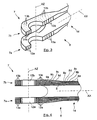
- the connecting rod according to the invention which appears in Figures 3 and 4 6 is marked by a double yoke 7 consisting of two wings 7a and 7b oriented parallel to each other, extending in the longitudinal direction of the rod, represented by the axis AX.
- This connecting rod consists of a set of reinforcing fiber base layers identified by 8a to 8e which surround a mandrel 11 in the form of a sleeve. At the end of this rod, that is to say in the region 7 corresponding to the wings 7a and 7b, additional intermediate layers 9a to 9d were interposed locally, between the consecutive base layers 8a to 8e.
- Each wing 7a, 7b consists of a thickness of reinforcing fibers corresponding substantially to twice the nominal thickness of reinforcing fibers constituting the rod 6, especially in its central region, that is to say in the tubular body.
- Each wing 7a, 7b further comprises an unmarked bore, in which is engaged a corresponding metal ring.
- These rings 12a and 12b constitute bearings aligned along an axis AZ normal to the axis AX, and they surround the mechanical axis on which the yoke is intended to be mounted, to distribute the wings in the forces exerted by this mechanical axis.
- each wing 7a and 7b extending in planes normal to the axis AZ are traversed by carbon pins which extend parallel to AZ direction to join to each other these different layers superimposed.
- the pins passing through the fiber layers of the wing 7a are marked 13a
- the pins passing through the fiber layers of the wing 7b are marked 13b.
- pins 13a and 13b are mounted by being inserted into the layers of reinforcing fibers when they are dry, that is to say prior to the injection of resin.
- the insertion of the pins into a yoke wing is advantageously provided with a vibrating support carrying the pins to be inserted, and which is progressively closer to the outer face of the yoke wing in which the pins are inserted, as detailed below.
- the pins can also be inserted according to other known methods, and generally responding to the name "z-pinning". In general, a density of spikes is expected of the order of three to five spikes per square centimeter.
- connection between the base layers 8a-8e and the intermediate layers 9a-9d is provided jointly by the polymerized resin and the pins.
- the pins 13a and 13b oppose the delamination of the various layers of reinforcing fibers by providing a tensile strength in the direction AZ, while the polymerized resin transfers the forces from one layer to another by offering a shear strength according to directions parallel to a plane normal to the axis AZ.
- the rod that is represented in Figures 3 and 4 may be manufactured in accordance with the process described in relationship with Figures 1 and 2 that is to say using a piece of carbon reinforcing fiber fabric, 2.5D type.
- the transverse fibers bonding the base layers of this fabric are cut in the regions corresponding to the wings of the yokes, and additional intermediate layers are interposed between the base layers disjunct locally at the wings.
- the piece of fabric thus modified is then installed on a mandrel for the insertion of the pins at the wings of the yokes, after which the assembly is then installed in a mold for resin injection and polymerization of this resin.
- the connecting rod can also be manufactured according to a method in which the base layers which constitute it, namely the layers 8a-8e are made by braiding around the mandrel, and in which the additional layers interposed at each wing clevis are applied by winding woven reinforcing fiber strips.
- the pins 13a and 13b are applied locally at the level of the clevis wings, along the direction AZ, to bind the base layers 8a-8e which are then braided layers, to the intermediate layers 9a-9d which are then coiled layers.
- the mandrel 11 extends along the longitudinal axis AX, in the form of a generally hollow sleeve having a shape generally of revolution about this axis.
- the cross section of the mandrel 11 is approximately circular in the central region 14, while at the first and second end, respectively marked 16 and 17, this section has a substantially rectangular shape.
- Two rods 18 and 19 are rigidly secured to the ends 16 and 17 of the mandrel 11, extending in the direction AX, to allow manipulation of the mandrel without having to grasp it by its outer face.
- This mandrel 11 which serves to support the layers of reinforcing fibers and to give the internal shape to the finished part, can be manufactured from layers of pre-impregnated carbon fiber fabric, the assembly then being pre-polymerized for it give the required mechanical rigidity.
- This machine 21 mainly comprises a ring 22 centered on the axis AX and carrying a series of coils of carbon fibers 23.
- the assembly being actuated by controlled and servocontrolled means, a sock of carbon fibers weaves around the outer face of the mandrel 11.
- the first braided carbon fiber base layer 8a surrounds the mandrel 11 over its entire length, and protrudes beyond its ends 16 and 17.
- a first band 9a is wound around the first end 16 of the mandrel 11, over this first base layer 8a, to form a local extra thickness reinforcing the wings of the double yoke 7.
- the first end of the connecting rod coincides with the first end 16 of the mandrel 11
- the central region of the connecting rod coincides with the central region 14 of the mandrel 11
- the second end of the connecting rod coincides with the second end 17 of the mandrel 11.
- the wound strip 9a is disposed in a generally helical shape with a substantially rectangular base, in accordance with the section of the end 16 of the mandrel 11 which it surrounds.
- the band 9a surrounds the end 16 on three turns of helicoid which are spaced apart from each other.
- helicoid turns can also be joined instead of spaced apart from one another, and on the other hand, several layers of strips can be wound successively around this first end, so as to increase the thickening thus introduced between two braided layers.
- this band can be performed manually, automatically or semi-automatically.
- this winding can be achieved with a winding machine comprising a ring surrounding the mandrel 11 being able to rotate around it, and carrying a coil of reinforcing fiber tape.
- the rotation of the ring and the advance of the mandrel along the axis AX make it possible to produce a winding having an adjustable pitch if necessary.
- the pins are inserted at each clevis flange, to increase the mechanical strength of the bonds connecting to each other the braided base layers and the wound interlayers.
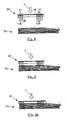
- the insertion of the pins in the clevis wing 7b is provided with a vibrating support which carries the pins 13b and which is lowered to the outer face of the wing 7b.
- the insertion of the pins in the other wing 7a is ensured in a similar manner.
- the vibrating support 24 comprises a base plate 26 equipped with a set of pins or the like 27 protruding from one of its faces, each being situated at a location of a pin to be inserted.
- a spacer of polypropylene, polystyrene or the like 28, having a thickness greater than the length of these lugs 27, is applied on the face bearing these lugs, so as to bear against the corresponding face of the base plate 26 and to be partially traversed by the lugs 27.
- Each pin 13b to be inserted in the yoke wing 7b is first "planted" in the free face of the spacer 28, opposite a corresponding lug 27, so as to have its end in support against the end of this lug 27.
- the spacer 28 is made of a sufficiently flexible material to be traversed on the one hand by the lugs 27 and on the other by the pins 13b.
- the vibrating support 24 which carries the various pins 13b not yet inserted, is positioned above the outer face of the clevis wing 7b.
- the means of vibrating this vibrating support are then activated, at the same time that the assembly is lowered towards the yoke wing, being subjected to a force indicated by F in the FIGS.
- the spacer 28 is made of a flexible and / or compressible material, the downward movement of the vibrating support 24 can nevertheless continue, under the effect of the force F, which compresses the spacer 28, thereby reducing its thickness.
- the lugs 27 which are rigid, penetrate partially through the first layers of fiber via the outer face of the wing 7b.
- the ends of the pins 13b are embedded in the wing 7b, instead of protruding from its outer face.
- a vibrating support 24 equipped with a spacer 28 of compressible material allows complete drowning of the pins 13b in the thickness of the clevis wing 7b, as shown schematically on the figure 12 .
- pins 13b are embedded in the thickness of the wing facilitates the installation of the assembly formed by the mandrel and the layers it carries in the mold for injecting and polymerizing the resin to bind the whole.
- the various layers of reinforcing fibers constituting the connecting rod have a certain compressibility in the radial direction, and these layers are compressed during installation in the mold, which further increases the density of fibers in the mold. the whole room.
- pins 13b are completely embedded in the thickness of the reinforcing fiber layers, they do not constitute an obstacle to the radial compression of these fiber layers that occurs when the assembly is installed in the injection mold.
- the clevis flange 7b has a thickness noted e before installation in the mold, and its thickness decreases to take the value e 'after installation in the mold.
- the double clevis is machined, and the bore can be made in each clevis flange, to mount the corresponding ring, as schematically illustrated in the figure 14 .
- the machining of the double yoke 7 can be provided for example by passing a saw mill at the first end of the blank, according to a plane containing the axis AX and oriented in a direction normal to the axis AZ .
- this saw mill allows forming a groove separating from one another the two wings or branches 7a and 7b of the double yoke 7, which are thus spaced a distance corresponding to the thickness of the cutter saw.
- the material which is wound around the first end is a reinforcing fiber link in the form of a woven fiber web. It is also possible to directly coil reinforcing fiber, or a ribbon, or a wick or a strand of reinforcing fibers. In a more general way, it is a matter of winding a link made of reinforcing fibers which are advantageously fibers of the same nature as the fibers of the base layers.
- the method is used to reinforce a rod end.
- the invention can find other applications: it is possible to wind one or more strips for example in a central region of the rod body and strengthen them by means of pins.
Landscapes
- Engineering & Computer Science (AREA)
- Mechanical Engineering (AREA)
- Chemical & Material Sciences (AREA)
- Composite Materials (AREA)
- General Engineering & Computer Science (AREA)
- Textile Engineering (AREA)
- Moulding By Coating Moulds (AREA)
- Shafts, Cranks, Connecting Bars, And Related Bearings (AREA)
- Casting Or Compression Moulding Of Plastics Or The Like (AREA)
- Braiding, Manufacturing Of Bobbin-Net Or Lace, And Manufacturing Of Nets By Knotting (AREA)
- Vehicle Body Suspensions (AREA)
Claims (5)
- Verfahren zum Herstellen einer Stange (6) aus Verbundwerkstoff, umfassend einen Gabelkopf (7), der dazu bestimmt ist, eine mechanische Achse aufzunehmen, wobei dieser Gabelkopf (7) zwei parallele Schenkel (7a, 7b) umfasst, die sich senkrecht zur Ausrichtung (AZ) der mechanischen Achse erstrecken, umfassend die Schritte:- Herstellen eines Dorns (11), der eine Einheit bildet, die ausreichend steif ist, um Faserschichten (8a-8e, 9a-9d) aufzunehmen,- Aufbringen auf diesen Dorn (11) von Basisschichten (8a-8e) aus verstärkenden Fasern, die die Stange (6) bilden, sowie von zusätzlichen Schichten (9a-9d), die im Bereich des Gabelkopfes (7, 7a, 7b) zwischen die Basisschichten (8a-8e) eingefügt werden, um dort Überdicken zu bilden,- Einfügen im Bereich jedes Schenkels (7a, 7b) des Gabelkopfes (7) von Stiften (13a, 13b), die die Zwischenschichten (9a-9d) und die Basisschichten (8a-8e) durchsetzen, indem sie sich entsprechend der Ausrichtung (AZ) der mechanischen Achse erstrecken, auf der dieser Gabelkopf (7) montiert werden soll,- Einspritzen von Harz in die Basisschichten (8a-8e) und in die Zwischenschichten (9a-9d) und Polymerisieren dieses Harzes.
- Verfahren nach Anspruch 1, wobei die Basisschichten (8a-8e) um den Dorn (11) geflochtene Schichten aus verstärkenden Fasern sind, und wobei jede Zwischenschicht (9a-9d) aus einem Band aus verstärkenden Fasern gebildet ist, das um den Dorn (11) und die Basisschicht oder Basisschichten (8a-8b), die erträgt, gewickelt ist.
- Verfahren nach Anspruch 2, wobei das für die Zwischenschichten (9a-9b) verwendete Band eine Gewebebahn aus verstärkenden Fasern ist.
- Verfahren nach einem der vorhergehenden Ansprüche, wobei die Stifte (13a, 13b) mittels eines schwingenden Trägers (24) eingefügt werden.
- Verfahren nach Anspruch 4, wobei der schwingende Träger (24) eine Basisplatte (26) umfasst, von der eine Seite Nasen (27) trägt, und wobei eine Strebe (28) aus komprimierbarem Material und mit einer Dicke, die größer als die Länge dieser Nasen (27) ist, an der die Nasen (27) tragenden Fläche angebracht ist, indem er teilweise von diesen Zapfen (27) durchsetzt wird, und wobei jeder Stift von dem schwingenden Träger (24) getragen wird, während er in der Strebe (26) gegenüber einer entsprechenden Nase (27) eingefügt ist.
Applications Claiming Priority (2)
| Application Number | Priority Date | Filing Date | Title |
|---|---|---|---|
| FR0905745A FR2953160A1 (fr) | 2009-11-30 | 2009-11-30 | Procede de fabrication d'une bielle en materiau composite integrant une chape renforcee |
| PCT/EP2010/007141 WO2011063953A2 (fr) | 2009-11-30 | 2010-11-25 | Procede de fabrication d'une bielle en materiau composite integrant une chape renforcee |
Publications (2)
| Publication Number | Publication Date |
|---|---|
| EP2507040A2 EP2507040A2 (de) | 2012-10-10 |
| EP2507040B1 true EP2507040B1 (de) | 2015-10-28 |
Family
ID=42133013
Family Applications (1)
| Application Number | Title | Priority Date | Filing Date |
|---|---|---|---|
| EP10787689.8A Active EP2507040B1 (de) | 2009-11-30 | 2010-11-25 | Verfahren zur herstellung einer verbindungsstrebe aus einem verbundstoff mit einer verstärkten gabel |
Country Status (9)
| Country | Link |
|---|---|
| US (1) | US20120318441A1 (de) |
| EP (1) | EP2507040B1 (de) |
| JP (1) | JP5497909B2 (de) |
| CN (1) | CN102741039A (de) |
| BR (1) | BR112012012894A2 (de) |
| CA (1) | CA2781941C (de) |
| FR (1) | FR2953160A1 (de) |
| RU (1) | RU2012127375A (de) |
| WO (1) | WO2011063953A2 (de) |
Cited By (1)
| Publication number | Priority date | Publication date | Assignee | Title |
|---|---|---|---|---|
| WO2019101468A1 (de) * | 2017-11-23 | 2019-05-31 | Zf Friedrichshafen Ag | Fahrwerksbauteil sowie kraftfahrzeug |
Families Citing this family (6)
| Publication number | Priority date | Publication date | Assignee | Title |
|---|---|---|---|---|
| FR2978935B1 (fr) | 2011-08-09 | 2013-08-23 | Messier Bugatti Dowty | Procede de fabrication d'une piece structurale en materiau composite comprenant une chape double orientee radialement |
| FR3000916B1 (fr) * | 2013-01-11 | 2015-02-20 | Aircelle Sa | Renforcement d'une chape en composites et orifice d'assemblage |
| CN104568661A (zh) * | 2014-12-31 | 2015-04-29 | 平湖市永光机械配件有限公司 | 一种粘度机的连杆头 |
| GB201510246D0 (en) * | 2015-06-12 | 2015-07-29 | Rolls Royce Plc | Method of manufacturing a composite component |
| CN105587752A (zh) * | 2015-12-09 | 2016-05-18 | 上海复合材料科技有限公司 | 复合材料连接杆及其制备方法 |
| FR3065182B1 (fr) | 2017-04-13 | 2019-06-21 | Safran | Procede de fabrication d'une piece en materiau composite comportant un corps prolonge par une extremite de fixation renforcee |
Family Cites Families (9)
| Publication number | Priority date | Publication date | Assignee | Title |
|---|---|---|---|---|
| US4704918A (en) * | 1985-02-19 | 1987-11-10 | Kamatics Corporation | Composite material force or motion transmitting member |
| JPH07224832A (ja) * | 1994-02-15 | 1995-08-22 | Mitsubishi Motors Corp | 繊維強化コネクティングロッド及びその製造方法 |
| EP0863811B1 (de) * | 1995-08-21 | 2003-10-15 | Foster-Miller, Inc. | System zur einfügung von bauteilen in verbundstrukturen |
| US5868886A (en) * | 1995-12-22 | 1999-02-09 | Alston; Mark S. | Z-pin reinforced bonded composite repairs |
| DK176135B1 (da) * | 2004-11-30 | 2006-09-18 | Lm Glasfiber As | Vakuuminfusion ved hjælp af semipermeabel membran |
| FR2890591B1 (fr) * | 2005-09-12 | 2012-10-19 | Eads | Procede de fabrication d'une piece composite rtm et piece composite obtenue selon ce procede |
| FR2893532B1 (fr) * | 2005-11-23 | 2008-02-15 | Messier Dowty Sa Sa | Procede de fabrication d'une chape sur un element structural en materiau composite, notamment une bielle |
| FR2893683B1 (fr) * | 2005-11-23 | 2008-02-01 | Messier Dowty Sa Sa | Procede de fabrication d'une bielle en materiau composite |
| KR100932302B1 (ko) * | 2007-09-17 | 2009-12-16 | 한국항공우주연구원 | 핀을 박아 성능을 보강한 복합재 적층 구조물, 상기 복합재적층 구조물 제조 방법, 장치 및 상기 장치 제작 방법 |
-
2009
- 2009-11-30 FR FR0905745A patent/FR2953160A1/fr not_active Withdrawn
-
2010
- 2010-11-25 CN CN2010800537295A patent/CN102741039A/zh active Pending
- 2010-11-25 BR BR112012012894A patent/BR112012012894A2/pt not_active IP Right Cessation
- 2010-11-25 EP EP10787689.8A patent/EP2507040B1/de active Active
- 2010-11-25 WO PCT/EP2010/007141 patent/WO2011063953A2/fr active Application Filing
- 2010-11-25 CA CA2781941A patent/CA2781941C/fr active Active
- 2010-11-25 US US13/512,469 patent/US20120318441A1/en not_active Abandoned
- 2010-11-25 RU RU2012127375/05A patent/RU2012127375A/ru not_active Application Discontinuation
- 2010-11-25 JP JP2012540316A patent/JP5497909B2/ja active Active
Cited By (1)
| Publication number | Priority date | Publication date | Assignee | Title |
|---|---|---|---|---|
| WO2019101468A1 (de) * | 2017-11-23 | 2019-05-31 | Zf Friedrichshafen Ag | Fahrwerksbauteil sowie kraftfahrzeug |
Also Published As
| Publication number | Publication date |
|---|---|
| CA2781941A1 (fr) | 2011-06-03 |
| CN102741039A (zh) | 2012-10-17 |
| RU2012127375A (ru) | 2014-01-10 |
| JP5497909B2 (ja) | 2014-05-21 |
| US20120318441A1 (en) | 2012-12-20 |
| WO2011063953A2 (fr) | 2011-06-03 |
| EP2507040A2 (de) | 2012-10-10 |
| JP2013512392A (ja) | 2013-04-11 |
| FR2953160A1 (fr) | 2011-06-03 |
| CA2781941C (fr) | 2015-11-24 |
| WO2011063953A3 (fr) | 2011-10-27 |
| BR112012012894A2 (pt) | 2017-03-01 |
Similar Documents
| Publication | Publication Date | Title |
|---|---|---|
| EP2507040B1 (de) | Verfahren zur herstellung einer verbindungsstrebe aus einem verbundstoff mit einer verstärkten gabel | |
| EP2509773B1 (de) | Verfahren zur herstellung einer verbindungsstrebe aus einem verbundstoff mit lokalisierter höherer stärke | |
| EP1342552B1 (de) | Verfahren zur Herstellung eines monolithischen, doppelwandigen und hitzbeständigen Verbundwerkstoffteiles und danach hergestelltes Verbundwerkstoffteil | |
| EP2946033B1 (de) | Faserstruktur für eine aus einem verbundwerkstoff hergestellte achsensymmetrische komponente mit sich progressiv änderndem durchmesser und bauteil damit | |
| BE1021537B1 (fr) | Bielle monobloc | |
| EP2282877B1 (de) | Verfahren zur herstellung eines teils mit einem hohlkörper aus einem verbundmaterial und danach hergestelltes teil | |
| WO2010149768A2 (fr) | Procede de fabrication de bielles composites et bielles obtenues selon le procede | |
| EP2681036B1 (de) | Bauteil aus einem verbundwerkstoff mit anlötelementen und herstellungsverfahren dafür | |
| FR2919283A1 (fr) | Piece mecanique comportant un insert en materiau composite. | |
| EP1798429B1 (de) | Rohrförmige Pleuelstange aus einem Verbundmaterial und ein entsprechendes Herstellungsverfahren | |
| EP2433024B1 (de) | Verfahren zur herstellung einer verbundmaterialverbindungsstange | |
| EP2741907B1 (de) | Verfahren zur herstellung eines strukturteils aus einem verbundstoff mit einem radial ausgerichteten doppeljoch | |
| EP2552677B1 (de) | Verfahren zur herstellung eines arms aus einem verbundstoff mit einem längslager für die aufnahme einer fixen oder rotierenden welle | |
| FR2955525A1 (fr) | Procede de fabrication d'une bielle en materiau composite comportant des zones de renforcement. |
Legal Events
| Date | Code | Title | Description |
|---|---|---|---|
| PUAI | Public reference made under article 153(3) epc to a published international application that has entered the european phase |
Free format text: ORIGINAL CODE: 0009012 |
|
| 17P | Request for examination filed |
Effective date: 20120531 |
|
| AK | Designated contracting states |
Kind code of ref document: A2 Designated state(s): AL AT BE BG CH CY CZ DE DK EE ES FI FR GB GR HR HU IE IS IT LI LT LU LV MC MK MT NL NO PL PT RO RS SE SI SK SM TR |
|
| DAX | Request for extension of the european patent (deleted) | ||
| GRAP | Despatch of communication of intention to grant a patent |
Free format text: ORIGINAL CODE: EPIDOSNIGR1 |
|
| INTG | Intention to grant announced |
Effective date: 20150520 |
|
| GRAS | Grant fee paid |
Free format text: ORIGINAL CODE: EPIDOSNIGR3 |
|
| GRAA | (expected) grant |
Free format text: ORIGINAL CODE: 0009210 |
|
| AK | Designated contracting states |
Kind code of ref document: B1 Designated state(s): AL AT BE BG CH CY CZ DE DK EE ES FI FR GB GR HR HU IE IS IT LI LT LU LV MC MK MT NL NO PL PT RO RS SE SI SK SM TR |
|
| REG | Reference to a national code |
Ref country code: GB Ref legal event code: FG4D Free format text: NOT ENGLISH |
|
| REG | Reference to a national code |
Ref country code: CH Ref legal event code: EP |
|
| REG | Reference to a national code |
Ref country code: FR Ref legal event code: PLFP Year of fee payment: 6 |
|
| REG | Reference to a national code |
Ref country code: AT Ref legal event code: REF Ref document number: 757690 Country of ref document: AT Kind code of ref document: T Effective date: 20151115 |
|
| REG | Reference to a national code |
Ref country code: IE Ref legal event code: FG4D Free format text: LANGUAGE OF EP DOCUMENT: FRENCH |
|
| REG | Reference to a national code |
Ref country code: DE Ref legal event code: R096 Ref document number: 602010028645 Country of ref document: DE |
|
| REG | Reference to a national code |
Ref country code: LT Ref legal event code: MG4D |
|
| REG | Reference to a national code |
Ref country code: NL Ref legal event code: MP Effective date: 20151028 |
|
| REG | Reference to a national code |
Ref country code: AT Ref legal event code: MK05 Ref document number: 757690 Country of ref document: AT Kind code of ref document: T Effective date: 20151028 |
|
| PG25 | Lapsed in a contracting state [announced via postgrant information from national office to epo] |
Ref country code: ES Free format text: LAPSE BECAUSE OF FAILURE TO SUBMIT A TRANSLATION OF THE DESCRIPTION OR TO PAY THE FEE WITHIN THE PRESCRIBED TIME-LIMIT Effective date: 20151028 Ref country code: NL Free format text: LAPSE BECAUSE OF FAILURE TO SUBMIT A TRANSLATION OF THE DESCRIPTION OR TO PAY THE FEE WITHIN THE PRESCRIBED TIME-LIMIT Effective date: 20151028 Ref country code: IS Free format text: LAPSE BECAUSE OF FAILURE TO SUBMIT A TRANSLATION OF THE DESCRIPTION OR TO PAY THE FEE WITHIN THE PRESCRIBED TIME-LIMIT Effective date: 20160228 Ref country code: IT Free format text: LAPSE BECAUSE OF FAILURE TO SUBMIT A TRANSLATION OF THE DESCRIPTION OR TO PAY THE FEE WITHIN THE PRESCRIBED TIME-LIMIT Effective date: 20151028 Ref country code: LT Free format text: LAPSE BECAUSE OF FAILURE TO SUBMIT A TRANSLATION OF THE DESCRIPTION OR TO PAY THE FEE WITHIN THE PRESCRIBED TIME-LIMIT Effective date: 20151028 Ref country code: NO Free format text: LAPSE BECAUSE OF FAILURE TO SUBMIT A TRANSLATION OF THE DESCRIPTION OR TO PAY THE FEE WITHIN THE PRESCRIBED TIME-LIMIT Effective date: 20160128 Ref country code: HR Free format text: LAPSE BECAUSE OF FAILURE TO SUBMIT A TRANSLATION OF THE DESCRIPTION OR TO PAY THE FEE WITHIN THE PRESCRIBED TIME-LIMIT Effective date: 20151028 |
|
| PG25 | Lapsed in a contracting state [announced via postgrant information from national office to epo] |
Ref country code: LV Free format text: LAPSE BECAUSE OF FAILURE TO SUBMIT A TRANSLATION OF THE DESCRIPTION OR TO PAY THE FEE WITHIN THE PRESCRIBED TIME-LIMIT Effective date: 20151028 Ref country code: PT Free format text: LAPSE BECAUSE OF FAILURE TO SUBMIT A TRANSLATION OF THE DESCRIPTION OR TO PAY THE FEE WITHIN THE PRESCRIBED TIME-LIMIT Effective date: 20160229 Ref country code: PL Free format text: LAPSE BECAUSE OF FAILURE TO SUBMIT A TRANSLATION OF THE DESCRIPTION OR TO PAY THE FEE WITHIN THE PRESCRIBED TIME-LIMIT Effective date: 20151028 Ref country code: SE Free format text: LAPSE BECAUSE OF FAILURE TO SUBMIT A TRANSLATION OF THE DESCRIPTION OR TO PAY THE FEE WITHIN THE PRESCRIBED TIME-LIMIT Effective date: 20151028 Ref country code: BE Free format text: LAPSE BECAUSE OF NON-PAYMENT OF DUE FEES Effective date: 20151130 Ref country code: AT Free format text: LAPSE BECAUSE OF FAILURE TO SUBMIT A TRANSLATION OF THE DESCRIPTION OR TO PAY THE FEE WITHIN THE PRESCRIBED TIME-LIMIT Effective date: 20151028 Ref country code: GR Free format text: LAPSE BECAUSE OF FAILURE TO SUBMIT A TRANSLATION OF THE DESCRIPTION OR TO PAY THE FEE WITHIN THE PRESCRIBED TIME-LIMIT Effective date: 20160129 Ref country code: FI Free format text: LAPSE BECAUSE OF FAILURE TO SUBMIT A TRANSLATION OF THE DESCRIPTION OR TO PAY THE FEE WITHIN THE PRESCRIBED TIME-LIMIT Effective date: 20151028 Ref country code: RS Free format text: LAPSE BECAUSE OF FAILURE TO SUBMIT A TRANSLATION OF THE DESCRIPTION OR TO PAY THE FEE WITHIN THE PRESCRIBED TIME-LIMIT Effective date: 20151028 |
|
| REG | Reference to a national code |
Ref country code: CH Ref legal event code: PL |
|
| PG25 | Lapsed in a contracting state [announced via postgrant information from national office to epo] |
Ref country code: CH Free format text: LAPSE BECAUSE OF NON-PAYMENT OF DUE FEES Effective date: 20151130 Ref country code: MC Free format text: LAPSE BECAUSE OF FAILURE TO SUBMIT A TRANSLATION OF THE DESCRIPTION OR TO PAY THE FEE WITHIN THE PRESCRIBED TIME-LIMIT Effective date: 20151028 Ref country code: CZ Free format text: LAPSE BECAUSE OF FAILURE TO SUBMIT A TRANSLATION OF THE DESCRIPTION OR TO PAY THE FEE WITHIN THE PRESCRIBED TIME-LIMIT Effective date: 20151028 Ref country code: LI Free format text: LAPSE BECAUSE OF NON-PAYMENT OF DUE FEES Effective date: 20151130 |
|
| REG | Reference to a national code |
Ref country code: DE Ref legal event code: R097 Ref document number: 602010028645 Country of ref document: DE |
|
| REG | Reference to a national code |
Ref country code: IE Ref legal event code: MM4A |
|
| PG25 | Lapsed in a contracting state [announced via postgrant information from national office to epo] |
Ref country code: EE Free format text: LAPSE BECAUSE OF FAILURE TO SUBMIT A TRANSLATION OF THE DESCRIPTION OR TO PAY THE FEE WITHIN THE PRESCRIBED TIME-LIMIT Effective date: 20151028 Ref country code: DK Free format text: LAPSE BECAUSE OF FAILURE TO SUBMIT A TRANSLATION OF THE DESCRIPTION OR TO PAY THE FEE WITHIN THE PRESCRIBED TIME-LIMIT Effective date: 20151028 Ref country code: RO Free format text: LAPSE BECAUSE OF FAILURE TO SUBMIT A TRANSLATION OF THE DESCRIPTION OR TO PAY THE FEE WITHIN THE PRESCRIBED TIME-LIMIT Effective date: 20151028 Ref country code: SK Free format text: LAPSE BECAUSE OF FAILURE TO SUBMIT A TRANSLATION OF THE DESCRIPTION OR TO PAY THE FEE WITHIN THE PRESCRIBED TIME-LIMIT Effective date: 20151028 Ref country code: SM Free format text: LAPSE BECAUSE OF FAILURE TO SUBMIT A TRANSLATION OF THE DESCRIPTION OR TO PAY THE FEE WITHIN THE PRESCRIBED TIME-LIMIT Effective date: 20151028 |
|
| PLBE | No opposition filed within time limit |
Free format text: ORIGINAL CODE: 0009261 |
|
| STAA | Information on the status of an ep patent application or granted ep patent |
Free format text: STATUS: NO OPPOSITION FILED WITHIN TIME LIMIT |
|
| 26N | No opposition filed |
Effective date: 20160729 |
|
| PG25 | Lapsed in a contracting state [announced via postgrant information from national office to epo] |
Ref country code: IE Free format text: LAPSE BECAUSE OF NON-PAYMENT OF DUE FEES Effective date: 20151125 |
|
| REG | Reference to a national code |
Ref country code: FR Ref legal event code: PLFP Year of fee payment: 7 |
|
| PG25 | Lapsed in a contracting state [announced via postgrant information from national office to epo] |
Ref country code: SI Free format text: LAPSE BECAUSE OF FAILURE TO SUBMIT A TRANSLATION OF THE DESCRIPTION OR TO PAY THE FEE WITHIN THE PRESCRIBED TIME-LIMIT Effective date: 20151028 |
|
| PG25 | Lapsed in a contracting state [announced via postgrant information from national office to epo] |
Ref country code: BG Free format text: LAPSE BECAUSE OF FAILURE TO SUBMIT A TRANSLATION OF THE DESCRIPTION OR TO PAY THE FEE WITHIN THE PRESCRIBED TIME-LIMIT Effective date: 20151028 Ref country code: HU Free format text: LAPSE BECAUSE OF FAILURE TO SUBMIT A TRANSLATION OF THE DESCRIPTION OR TO PAY THE FEE WITHIN THE PRESCRIBED TIME-LIMIT; INVALID AB INITIO Effective date: 20101125 |
|
| REG | Reference to a national code |
Ref country code: FR Ref legal event code: CD Owner name: MESSIER-BUGATTI-DOWTY, FR Effective date: 20170518 |
|
| PG25 | Lapsed in a contracting state [announced via postgrant information from national office to epo] |
Ref country code: CY Free format text: LAPSE BECAUSE OF FAILURE TO SUBMIT A TRANSLATION OF THE DESCRIPTION OR TO PAY THE FEE WITHIN THE PRESCRIBED TIME-LIMIT Effective date: 20151028 |
|
| PG25 | Lapsed in a contracting state [announced via postgrant information from national office to epo] |
Ref country code: MT Free format text: LAPSE BECAUSE OF FAILURE TO SUBMIT A TRANSLATION OF THE DESCRIPTION OR TO PAY THE FEE WITHIN THE PRESCRIBED TIME-LIMIT Effective date: 20151028 |
|
| REG | Reference to a national code |
Ref country code: FR Ref legal event code: PLFP Year of fee payment: 8 |
|
| PG25 | Lapsed in a contracting state [announced via postgrant information from national office to epo] |
Ref country code: LU Free format text: LAPSE BECAUSE OF NON-PAYMENT OF DUE FEES Effective date: 20151125 |
|
| PG25 | Lapsed in a contracting state [announced via postgrant information from national office to epo] |
Ref country code: TR Free format text: LAPSE BECAUSE OF FAILURE TO SUBMIT A TRANSLATION OF THE DESCRIPTION OR TO PAY THE FEE WITHIN THE PRESCRIBED TIME-LIMIT Effective date: 20151028 Ref country code: MK Free format text: LAPSE BECAUSE OF FAILURE TO SUBMIT A TRANSLATION OF THE DESCRIPTION OR TO PAY THE FEE WITHIN THE PRESCRIBED TIME-LIMIT Effective date: 20151028 |
|
| REG | Reference to a national code |
Ref country code: FR Ref legal event code: PLFP Year of fee payment: 9 |
|
| PG25 | Lapsed in a contracting state [announced via postgrant information from national office to epo] |
Ref country code: AL Free format text: LAPSE BECAUSE OF FAILURE TO SUBMIT A TRANSLATION OF THE DESCRIPTION OR TO PAY THE FEE WITHIN THE PRESCRIBED TIME-LIMIT Effective date: 20151028 |
|
| PGFP | Annual fee paid to national office [announced via postgrant information from national office to epo] |
Ref country code: GB Payment date: 20231019 Year of fee payment: 14 |
|
| PGFP | Annual fee paid to national office [announced via postgrant information from national office to epo] |
Ref country code: FR Payment date: 20231019 Year of fee payment: 14 Ref country code: DE Payment date: 20231019 Year of fee payment: 14 |