EP2506072A1 - Aperture mechanism - Google Patents
Aperture mechanism Download PDFInfo
- Publication number
- EP2506072A1 EP2506072A1 EP10832866A EP10832866A EP2506072A1 EP 2506072 A1 EP2506072 A1 EP 2506072A1 EP 10832866 A EP10832866 A EP 10832866A EP 10832866 A EP10832866 A EP 10832866A EP 2506072 A1 EP2506072 A1 EP 2506072A1
- Authority
- EP
- European Patent Office
- Prior art keywords
- aperture
- passage opening
- edge portions
- light passage
- aperture blades
- Prior art date
- Legal status (The legal status is an assumption and is not a legal conclusion. Google has not performed a legal analysis and makes no representation as to the accuracy of the status listed.)
- Granted
Links
Images






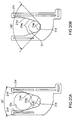


Classifications
-
- G—PHYSICS
- G03—PHOTOGRAPHY; CINEMATOGRAPHY; ANALOGOUS TECHNIQUES USING WAVES OTHER THAN OPTICAL WAVES; ELECTROGRAPHY; HOLOGRAPHY
- G03B—APPARATUS OR ARRANGEMENTS FOR TAKING PHOTOGRAPHS OR FOR PROJECTING OR VIEWING THEM; APPARATUS OR ARRANGEMENTS EMPLOYING ANALOGOUS TECHNIQUES USING WAVES OTHER THAN OPTICAL WAVES; ACCESSORIES THEREFOR
- G03B9/00—Exposure-making shutters; Diaphragms
- G03B9/02—Diaphragms
Definitions
- the present invention relates to an aperture stop mechanism, and relates particularly to an aperture stop mechanism which drives two aperture blades and adjusts an aperture area of a light passage opening into which light for imaging is introduced.
- the shape of the light passage opening is a diamond shape. If the shape of the light passage opening is a diamond shape, for example when photographing is performed so that the background is defocused to make a subject prominent, a blurred image of the background has a diamond shape, so that the background may become unnatural. Meanwhile, in order to avoid such a phenomenon, as described in the Patent Literature 3, there is considered a technique for switching to adjustment of exposure using an electronic shutter before the aperture area of the light passage opening is reduced so small. However, if the switching to the electronic shutter is performed before the aperture area of the light passage opening is reduced so small, strong light is applied to an imaging device, and this may cause influence on image quality such as smear.
- the present invention has been made in order to solve the above problem and it is therefore an object of the present invention to provide an aperture stop mechanism which suppresses unnaturalness of a blurred image of the background.
- an aperture stop mechanism in an embodiment of the present invention comprises two aperture blades and a drive mechanism.
- the two aperture blades are arranged so as to overlap each other and form a single light passage opening into which light utilized in imaging is introduced with the respective edge portions of the two aperture blades.
- the drive mechanism drives the two aperture blades in directions different from each other and thereby changes the aperture area of the light passage opening.
- the two aperture blades are provided so as to form the single light passage opening, surrounded by boundaries including five or more straight lines, with the respective edge portions of the two aperture blades.
- the present invention can provide an aperture stop mechanism which suppresses unnaturalness of a blurred image of the background.
- FIG. 1 is a front view of an aperture stop mechanism 10 according to the first embodiment.
- the aperture stop mechanism 10 has a base unit 12 and two aperture blades 14 and 16.
- the two aperture blades 14 and 16 are provided movable in a vertical direction in FIG. 1 so as to be spaced apart from and approached to each other.
- the direction in which each of the two aperture blades 14 and 16 can be moved is referred to as a "vertical direction”.
- a direction perpendicular to the direction in which each of the two aperture blades 14 and 16 can be moved is referred to as a "horizontal direction”.
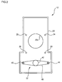
- FIG. 2 is a front view of the base unit 12.
- the base unit 12 has a base plate 20, a drive mechanism 22, and guide pins 24, 26, 28, and 30.
- the base plate 20 is formed into a substantially rectangular plate shape extending in the vertical direction, and an edge portion is vertically bent to provide a flange.
- a fixed aperture hole 20a which is a circular opening portion is provided at the substantially center of the base plate 20.
- the drive mechanism 22 has a swing rod 40, a swing shaft 42, and connecting pins 44 and 46.
- the swing shaft 42 is attached near an end of the guide pin 30.
- the center of the swing rod 40 is swingably supported by the swing shaft 42.
- the connecting pins 44 and 46 are provided at the respective ends of the swing rod 40 so that the axial direction is vertical to the base plate 20.
- the guide pins 24, 26, 28, and 30 are each provided around the fixed aperture hole 20a and arranged on the base plate 20 so that the axial directions protrude so as to face perpendicular with respect to the base plate 20. Specifically, the guide pins 24 and 26 and the guide pins 28 and 30 are respectively arranged to be aligned in the horizontal direction. The guide pins 28 and 30 are arranged at a position near the drive mechanism 22 in comparison with the guide pins 24 and 26. The guide pins 24 and 28 are arranged to be aligned with the connecting pin 44 in the vertical direction. The guide pins 26 and 30 are arranged to be aligned with the connecting pin 46 in the vertical direction.
- FIG. 3 is a front view of the aperture blade 14.
- the aperture blade 14 is formed into a plate shape having a recess 14a formed so as to be incised.
- the aperture blade 14 has long guide holes 14b, 14c, and 14d and a connecting hole 14e.
- the guide holes 14b, 14c, and 14d are each provided extending in the vertical direction.
- the guide holes 14b and 14d and the connecting hole 14e are arranged to be aligned in the vertical direction in this order.
- the guide holes 14b and 14d are formed extending on the same straight line.
- the connecting hole 14e is formed extending in the horizontal direction.
- the guide holes 14c and 14b are formed to be aligned in the horizontal direction.
- the recess 14a is provided between the guide holes 14b and 14c.
- a pair of first edge portions 14f is, at its one end, connected to the recess 14a and formed extending in parallel with the vertical direction.
- the recess 14a includes a pair of second edge portions 14g and a pair of third edge portions 14h.
- the second edge portions 14g as a pair are each formed linearly and have the same length.
- Each one end of the pair of second edge portions 14g is connected to each one end of the pair of first edge portions 14f extending in parallel with the vertical direction.
- Each of the pair of second edge portions 14g is inclined at a predetermined angle with respect to the vertical direction so as to approach to each other as they approach to the other end.
- the third edge portions 14h as a pair are each formed linearly and have the same length, and each one end is connected to the other end of each of the pair of second edge portions 14g.
- the other ends of the third edge portions 14h as a pair are connected to each other.
- Each of the pair of third edge portions 14h is inclined at a predetermined angle with respect to the vertical direction so as to approach to each other as they approach to the other end.
- the inclination angle of the third edge portion 14h with respect to the vertical direction is larger than the inclination angle of the second edge portion 14g with respect to the vertical direction.
- the recess 14a is formed symmetrically around a line passing through an intersection P1 of the pair of third edge portions 14h and parallel to the vertical direction.
- FIG. 4 is a front view of the aperture blade 16.
- the aperture blade 16 is formed into a plate shape having a recess 16a formed so as to be incised.
- the aperture blade 16 has long guide holes 16b, 16c, and 16d and a connecting hole 16e.
- the guide holes 16b, 16c, and 16d are each provided extending in the vertical direction.
- the guide holes 16c and 16d and the connecting hole 16e are formed to be aligned in the vertical direction in this order.
- the guide holes 16b and 16d are formed extending on the same straight line.
- the connecting hole 16e is formed extending in the horizontal direction.
- the guide hole 16b is formed to be aligned with the guide hole 16c in the horizontal direction.
- the recess 16a is provided between the guide holes 16b and 16c.
- the recess 16a includes a pair of second edge portions 16g and a pair of third edge portions 16h.
- the inside of the guide hole 16d has a first edge portion 16f extending in the vertical direction.
- first edge portion 16f extending in the vertical direction.
- second edge portions 16g its one end is connected to an end of the first edge portion 16f.
- the second edge portions 16g as a pair are each formed linearly, have the same length, and are inclined at a predetermined angle with respect to the vertical direction so as to approach to each other as they approach to the other end.
- the third edge portions 16h as a pair are each formed linearly and have the same length, and each one end of the third edge portions 16h is connected to the other end of each of the pair of second edge portions 16g. In the pair of third edge portions 16h, the other ends are connected to each other.
- Each of the pair of third edge portions 16h is inclined at a predetermined angle with respect to the vertical direction so as to approach to each other as they approach to the other end. At this time, the inclination angle of the third edge portion 16h with respect to the vertical direction is larger than the inclination angle of the second edge portion 16g with respect to the vertical direction.
- the recess 16a is formed symmetrically around a line passing through an intersection P2 of the pair of third edge portions 16h and parallel to the vertical direction.
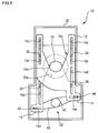
- FIG. 5 is a front view of the aperture stop mechanism 10 when the two aperture blades 14 and 16 are attached to the base unit 12.
- the aperture blade 16 is attached to the base plate 20.
- the guide pin 24 is inserted into the guide hole 16b
- the guide pin 26 is inserted into the guide hole 16c
- the guide pin 30 is inserted into the guide hole 16d.
- the aperture blade 16 can be moved in the vertical direction, and the movement in the horizontal direction is limited.
- the connecting pin 46 of the swing rod 40 is inserted into the connecting hole 16e.
- the aperture blade 14 is attached to the base plate 20 so as to be superposed on the aperture blade 16.
- the guide pin 24 is inserted into the guide hole 14b
- the guide pin 26 is inserted into the guide hole 14c
- the guide pin 28 is inserted into the guide hole 14d.
- the aperture blade 14 can be moved in the vertical direction, and the movement in the horizontal direction is limited.
- the connecting pin 44 of the swing rod 40 is inserted into the connecting hole 14e.
- the recesses 14a and 16a are opened to face each other.
- a single light passage opening 50 into which light utilized for imaging is introduced is constituted of the recesses 14a and 16a as the edge portions.
- the drive mechanism 22 swings the swing rod 40 to thereby drive the two aperture blades 14 and 16 in directions opposite to each other in parallel with the vertical direction so that the aperture blades 14 and 16 are approached to and spaced apart from each other, so that the aperture area of the light passage opening 50 is changed.
- the two aperture blades 14 and 16 may be each provided movably so as to curve, for example. Also in this case, the drive mechanism 22 drives the two aperture blades 14 and 16 in directions different from each other, whereby the aperture area of the light passage opening 50 may be changed.
- the drive mechanism 22 drives the two aperture blades 14 and 16 so that the aperture area of the light passage opening 50 is adjusted within a predetermined range. Specifically, the drive mechanism 22 drives the two aperture blades 14 and 16 from a minimum aperture position where the aperture area of the light passage opening 50 is minimum to a maximum aperture position where the aperture area of the light passage opening 50 is maximum.
- FIG. 6A is a view showing a method of determining a shape of the recess 14a.
- the pair of first edge portions 14f is formed so that an interval between the first edge portions 14f is the same as or slightly larger than the fixed aperture hole 20a.
- the pair of second edge portions 14g is formed so that the second edge portions 14g form 45°. Accordingly, the pair of second edge portions 14g is inclined at 22. 5° with respect to the vertical direction.
- the pair of second edge portions 14g is provided at a position circumscribed with the fixed aperture hole 20a when the aperture blade 14 is located at the maximum aperture position.
- FIG. 6B is a view showing the method of determining the shape of the recess 14a.
- a virtual circle C1 having the aperture area for realizing the most frequently used F value is inscribed with the pair of second edge portions 14g determined in FIG. 6A .
- the most frequently used F value is 4. It will be understood that the F value at this time is not limited to 4.
- the pair of third edge portions 14h is formed so that the third edge portions form an interior angle of 135°. Accordingly, the pair of third edge portions 14h is inclined at 67.5° with respect to the vertical direction and formed so that the third edge portions 14h and the second edge portions 14g form an interior angle of 135°.
- the pair of third edge portions 14h is formed to be circumscribed with the virtual circle C1. Thus, each shape of the pair of first edge portions 14f, the pair of second edge portions 14g, and the pair of third edge portions 14h is determined.
- the recess 16a is formed into the same shape as the recess 14a except that the opening direction is opposite. Accordingly, the pair of second edge portions 16g is inclined at 22. 5° with respect to the vertical direction, and the pair of third edge portions 16h is inclined at 67. 5° with respect to the vertical direction.
- the pair of second edge portions 16g is similar to the pair of second edge portions 14g in that the pair of second edge portions 16g is provided to be circumscribed with the fixed aperture hole 20a when the aperture blade 16 is located at the maximum aperture position.
- the recess 16a may be formed into a shape different from the recess 14a.
- FIGS. 7A to 7E are views showing a change of the shape of the light passage opening 50 when the two aperture blades 14 and 16 are approached to each other. For ease of understanding, each shape of the two aperture blades 14 and 16 is schematically shown.
- FIG. 7A is a front view of the aperture stop mechanism 10 when the two aperture blades 14 and 16 are located at the maximum aperture position to which the two aperture blades 14 and 16 move the most so that the light amount passing through the light passage opening 50 is maximum.
- the aperture area of the light passage opening 50 is the aperture area of the fixed aperture hole 20a.
- FIG. 7B is a front view of the aperture mechanism 10 when each of the two aperture blades 14 and 16 is approached to each other by a predetermined distance from the maximum aperture position.
- a portion of the pair of second edge portions 14g and a portion of the pair of second edge portions 16g are located inside the fixed aperture hole 20a, and a part of light to be passed through the fixed aperture hole 20a is shielded.
- the pair of third edge portions 14h and the pair of third edge portions 16h remain located outside the fixed aperture hole 20a.
- the light passage opening 50 at this time is defined by the pair of second edge portions 14g, the pair of the second edge portions 16g, and the fixed aperture hole 20a.
- FIG. 7C is a front view of the aperture mechanism 10 when each of the two aperture blades 14 and 16 is further approached to each other by a predetermined distance from the state of FIG. 7B .
- the pair of third edge portions 14h and the pair of third edge portions 16h are located inside the fixed aperture hole 20a.
- the boundaries constituted of the second edge portions 14g and the second edge portions 16g are longer than the third edge portion 14h and the third edge portion 16h.
- the light passage opening 50 has a flat shape whose width in the vertical direction is larger than the width in the horizontal direction.
- FIG. 7D is a front view of the aperture mechanism 10 when each of the two aperture blades 14 and 16 is further approached to each other by a predetermined distance from the state of FIG. 7C .
- the flatness of the light passage opening 50 is gradually reduced, and the width in the vertical direction is equal to the width in the horizontal direction.
- FIG. 7D shows the state at this time.
- the boundaries constituted of the second edge portion 14g and the second edge portion 16g have the same length as the third edge portion 14h and the third edge portion 16h. Accordingly, in the light passage opening 50, eight edge portions constituting the boundary have the same length, and since the eight edge portions form 135° with the adjacent edge portions, the light passage opening 50 is a regular octagon.
- the regular octagon is formed to be circumscribed with the virtual circle C1.
- the light passage opening 50 can have the shape closest to the virtual circle C1. It will be understood that the shape of the light passage opening 50 at this time is not limited to the regular octagon, and the shape may be an octagon other than the regular octagon, for example.
- the boundaries constituting the light passage opening 50 are constituted of curved lines, especially when outside is bright, an influence on image quality called "ghost" easily occurs.
- the boundaries of the light passage opening 50 are constituted thus, whereby the ghost can be suppressed.
- the two aperture blades 14 and 16 may be formed so that the light passage opening 50 has the shape closest to the virtual circle C1 for example when an F value larger than the most frequently used F value is realized. According to this constitution, the flatness of the light passage opening 50 can be reduced when outside is bright, and the influence on image quality due to the flatness of the light passage opening 50 can be suppressed.
- the two aperture blades 14 and 16 may be formed so that the light passage opening 50 has the shape closest to the virtual circle C1 when an F value smaller than the most frequently used F value is realized.
- FIG. 7E is a front view of the aperture stop mechanism 10 when the two aperture blades 14 and 16 are located at the minimum aperture position.
- the light passage opening 50 becomes flat so that the width in the horizontal direction is longer than the width in the vertical direction. Even when the two aperture blades 14 and 16 are located at the minimum aperture position thus, the light passage opening 50 has a flat shape. Even when the two aperture blades 14 and 16 reach the minimum aperture position thus, the light passage opening 50 surrounded by the boundary constituted of the eight straight lines is constituted of the edge portions of the two aperture blades 14 and 16.
- the boundaries of the light passage opening 50 are constituted of the eight straight lines when the two aperture blades 14 and 16 are located at the minimum aperture position, whereby it turns out that in comparison with a case where a diamond-shaped light passage opening is constituted of four straight lines, unnaturalness of a blurred image of the background can be substantially reduced. Accordingly, according to the aperture stop mechanism 10, the unnaturalness of the blurred image of the background and the ghost can be suitably suppressed.
- the boundaries thereof may include not only straight lines but also curved lines.
- a connecting portion of the pair of third edge portions 14h and a connecting portion of the pair of third edge portions 16h may be curved lines.
- a connecting portion between the second edge portion 14g and the third edge portions 14h and a connecting portion between the second edge portion 16g and the third edge portions 16h may be curved lines.
- the drive mechanism 22 moves the two aperture blades 14 and 16 to the minimum aperture position.
- the predetermined value of the F value at this time is a value of not less than 5 and not more than 6.
- the electronic control unit is constituted of microcomputer, ROM, RAM, and so on.
- the electronic control unit adjusts the storage time of the imaging device thus and thereby substantially adjusts the amount of light passing through the light passage opening 50 and utilized for imaging.
- the electronic control unit functions as light amount adjustment means.
- Such an exposure adjustment according to control of the imaging device is called an "electronic shutter".
- the imaging apparatus mounted with the aperture stop mechanism 10 has mechanical light amount adjustment means according to the aperture stop mechanism 10 and the electronic shutter.
- the electronic control unit detects brightness of outside utilizing a detection signal from the imaging device.
- the electronic control unit sets the F value to be realized utilizing the detected brightness of outside.
- the drive mechanism 22 drives the two aperture blades 14 and 16 between the maximum aperture position and the minimum aperture position and adjusts an actual F value by means of the mechanical light amount adjustment means according to the aperture stop mechanism 10.
- the drive mechanism 22 moves the two aperture blades 14 and 16 to the minimum aperture position and avoids further adjustment of the F value in the mechanical light amount adjustment means according to the aperture stop mechanism 10.
- the electronic control unit adjusts the storage time of the imaging device so as to substantially realize the F value set larger than the predetermined value.
- the aperture stop mechanism 10 as the mechanical light amount adjustment means and the electronic shutter are used in combination, whereby this constitution can correspond to a large F value while suppressing the flatness ratio of the light passage opening 50 at the minimum aperture position.
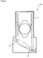
- FIG. 8 is a view showing the shape of the light passage opening 50 when the two aperture blades 14 and 16 are located at the minimum aperture position. At this time, the width in the horizontal direction of the light passage opening 50 is maximum.
- the two aperture blades 14 and 16 are each formed so that the flatness ratio of the light passage opening 50 obtained by dividing a horizontal direction length L12 at this time by a vertical direction length L11 is more than 1 and not more than 1.4.
- the flatness ratio of the light passage opening 50 is set to such a value when the two aperture blades 14 and 16 are located at the minimum aperture position, whereby it turns out that while the unnaturalness of the blurred image of the background is suppressed, smear and so on are suppressed even if a large F value is set, and smooth switching to the electronic shutter can be performed.
- FIG. 9 is a front view of an aperture stop mechanism 100 according to the second embodiment.
- the configurations of the aperture stop mechanism 100 and an imaging apparatus mounted with the aperture stop mechanism 100 are similar to those of the first embodiment.
- components similar to those in the first embodiment are denoted by the same reference numerals, and descriptions thereof are omitted.
- the aperture stop mechanism 100 has a base unit 12 and two aperture blades 114 and 116.
- the two aperture blades 114 and 116 are provided movable in a vertical direction so as to be spaced apart from and approached to each other.
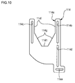
- FIG. 10 is a front view of an aperture blade 114.
- the aperture blade 114 is formed into a plate shape having a recess 114a formed so as to be incised.
- the aperture blade 114 has long guide holes 114b, 114c, and 114d and a connecting hole 114e.
- the shape and arrangement are similar to those of the guide holes 14b, 14c, and 14d and the connecting hole 14e according to the first embodiment.
- a pair of first edge portions 114f is formed similarly to the pair of first edge portions 14f.
- the recess 114a is provided between the guide holes 114b and 114c.
- the recess 114a includes a pair of second edge portions 114g and a pair of third edge portions 114h.
- the second edge portions 114g as a pair are each formed linearly and have the same length, and each one end is connected to each of the pair of first edge portions 114f.
- Each of the pair of second edge portions 114g is inclined at a predetermined angle with respect to the vertical direction so as to approach to each other as they approach the other end.
- the third edge portion 114h is formed extending in the horizontal direction, and the both ends are connected to the respective other ends of the second edge portions 114g as a pair.
- the recess 114a is formed symmetrically around a line passing through the midpoint of the third edge portion 114h and parallel to the vertical direction.
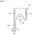
- FIG. 11 is a front view of the aperture blade 116.
- the aperture blade 116 is formed into a plate shape having a recess 116a formed so as to be incised.
- the aperture blade 116 has long guide holes 116b, 116c, and 116d and a connecting hole 116e.
- the shape and arrangement of the guide holes 116b, 116c, 116d and the connecting hole 116e are similar to those of the guide holes 14b, 14c, and 14d and the connecting hole 14e according to the first embodiment.
- the first edge portion 116f is formed similarly to the pair of first edge portions 16f.
- the recess 116a is provided between the guide holes 116b and 116c.
- the recess 116a includes a pair of second edge portions 116g and a third edge portion 116h.
- the pair of second edge portions 116g its one end is connected to an end of the first edge portion 116f.
- the second edge portions 116g as a pair are formed linearly, have the same length, and are inclined at a predetermined angle with respect to the vertical direction so as to approach to each other as they approach the other end.
- the third edge portion 116h is formed extending in the horizontal direction, and the both ends are connected to the respective other ends of the second edge portions 116g as a pair.
- the recess 116a is formed symmetrically around a line passing through the midpoint of the third edge portion 116h and parallel to the vertical direction.
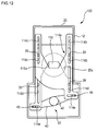
- FIG. 12 is a front view of the aperture stop mechanism 10 when the two aperture blades 114 and 116 are attached to the base unit 12.
- a method of attaching the two aperture blades 114 and 116 to the base unit 12 is similar to the method of attaching the two aperture blades 14 and 16.
- the recesses 114a and 116a are opened to face each other.
- a single light passage opening 150 into which light utilized in imaging is introduced is constituted of both the recesses 114a and 116a as the respective edge portions of the two aperture blades 114 and 116.
- a drive mechanism 22 swings a swing rod 40 to thereby drive the two aperture blades 114 and 116 in directions opposite to each other in parallel with the vertical direction so that the aperture blades 114 and 116 are approached to and spaced apart from each other, so that the aperture area of the light passage opening 150 is changed.
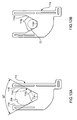
- FIG. 13A is a view showing a method of determining the shape of the recess 114a.
- the pair of first edge portions 114f is formed so that an interval between the first edge portions 114f is the same as or slightly larger than a fixed aperture hole 20a.
- the pair of second edge portions 114g is formed so that the second edge portions 114g form 60°. Accordingly, the pair of second edge portions 114g is each inclined at 30° with respect to the vertical direction.
- the pair of second edge portions 114g is each provided at a position circumscribed with the fixed aperture hole 20a when the aperture blade 114 is located at the maximum aperture position.
- FIG. 13B is a view showing the method of determining the shape of the recess 114a.
- a virtual circle C1 having the aperture area for realizing the most frequently used F value is inscribed with the pair of second edge portions 114g determined in FIG. 13A .
- the third edge portion 114h is formed to be circumscribed with the virtual circle C1 while extending in the horizontal direction.
- each shape of the pair of first edge portions 114f, the pair of second edge portions 114g, and the pair of third edge portions 114h is determined.
- the recess 116a is formed into the same shape as the recess 114a except that the opening direction is opposite. Accordingly, the pair of second edge portions 116g is inclined at 30° with respect to the vertical direction, and the third edge portion 116h is formed extending in the horizontal direction.
- the pair of second edge portions 116g is similar to the pair of second edge portions 114g in that the pair of second edge portions 116g is provided to be circumscribed with the fixed aperture hole 20a when the aperture blade 116 is located at the maximum aperture position.
- the recess 116a may be formed into a shape different from the recess 114a.
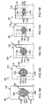
- FIGS. 14A to 14E are views showing a change of the shape of the light passage opening 150 when the two aperture blades 114 and 116 are approached to each other. For ease of understanding, each shape of the two aperture blades 114 and 116 is schematically shown.
- FIG. 14A is a front view of the aperture stop mechanism 10 when the two aperture blades 114 and 116 are located at the maximum aperture position to which the two aperture blades 114 and 116 move the most so that the light amount passing through the light passage opening 50 is maximum.
- the aperture area of the light passage opening 150 is the aperture area of the fixed aperture hole 20a.
- FIG. 14B is a front view of the aperture mechanism 10 when the two aperture blades 114 and 116 are approached to each other by a predetermined distance from the maximum aperture position.
- a portion of the pair of second edge portions 114g and a portion of the pair of the second edge portions 116g are located inside the fixed aperture hole 20a, and a part of light to be passed through the fixed aperture hole 20a is shielded.
- the third edge portion 114h and the third edge portion 116h remain located outside the fixed aperture hole 20a.
- the light passage opening 50 at this time is defined by the pair of second edge portions 114g, the pair of the second edge portions 116g, and the fixed aperture hole 20a.
- FIG. 14C is a front view of the aperture mechanism 10 when the two aperture blades 114 and 116 are further approached to each other by a predetermined distance from the state of FIG. 14B .
- the third edge portion 114h and the third edge portion 116h are located inside the fixed aperture hole 20a.
- the boundaries constituted of the second edge portions 114g and the second edge portions 116g are longer than the third edge portion 114h and the third edge portion 116h.
- the light passage opening 150 has a flat shape whose width in the vertical direction is larger than the width in the horizontal direction.
- FIG. 14D is a front view of the aperture mechanism 10 when the two aperture blades 114 and 116 are further approached to each other by a predetermined distance from the state of FIG. 14C .
- the flatness of the light passage opening 150 is gradually reduced, and the light passage opening 150 has a shape circumscribed with a virtual circle C1.
- FIG. 14D shows the state at this time.
- the boundaries constituted of the second edge portion 114g and the second edge portion 116g have the same length as the third edge portion 114h and the third edge portion 116h. Accordingly, in the light passage opening 150, six edge portions constituting the boundary have the same length, and since the six edge portions form 120° with the adjacent edge portions, the light passage opening 150 is a regular hexagon.
- the regular hexagon is formed to be circumscribed with the virtual circle C1.
- the light passage opening 150 can have the shape closest to the virtual circle C1. It will be understood that the shape of the light passage opening 150 at this time is not limited to the regular hexagon, and the shape may be a hexagon other than the regular hexagon, for example.
- the two aperture blades 114 and 116 may be formed so that the light passage opening 150 has the shape closest to the virtual circle C1 when an F value larger than the most frequently used F value is realized, for example.
- the two aperture blades 114 and 116 may be formed so that the light passage opening 150 has the shape closest to the virtual circle C1 when an F value smaller than the most frequently used F value is realized.
- FIG. 14E is a front view of the aperture stop mechanism 10 when the two aperture blades 114 and 116 are located at the minimum aperture position.
- the light passage opening 150 becomes flat so that the width in the horizontal direction is longer than the width in the vertical direction.
- the light passage opening 150 has a flat shape.
- the two aperture blades 114 and 116 are provided so as to form the light passage opening 150, surrounded by the boundaries including six straight lines, with the edge portions of the two aperture blades 114 and 116 when the two aperture blades 114 and 116 reach the minimum aperture position.
- the boundaries of the light passage opening 150 are constituted of the six straight lines when the two aperture blades 114 and 116 are located at the minimum aperture position, whereby it turns out that in comparison with a case where a diamond-shaped light passage opening is constituted of four straight lines, unnaturalness of a so-called blurred image of the background can be substantially reduced.
- the boundaries thereof may include not only straight lines but also curved lines.
- a connecting portion between the second edge portion 114g and the third edge portions 114h and a connecting portion between the second edge portion 116g and the third edge portions 116h may be curved lines.
- the drive mechanism 22 moves the two aperture blades 114 and 116 to the minimum aperture position and avoids further adjustment of the F value in the mechanical light amount adjustment means according to the aperture stop mechanism 100.
- the electronic control unit adjusts the storage time of the imaging device so as to substantially realize the F value set larger than the predetermined value.
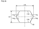
- FIG. 15 is a view showing the shape of the light passage opening 150 when the two aperture blades 114 and 116 are located at the minimum aperture position.
- the width in the vertical direction of the light passage opening 150 is minimum, and the width in the horizontal direction is maximum.
- the two aperture blades 114 and 116 are each formed so that the flatness ratio of the light passage opening 150 obtained by dividing a horizontal direction length L22 at this time by a vertical direction length L21 is more than 1 and not more than 1.4.
- the flatness ratio of the light passage opening 150 is set to such a value, whereby while unnaturalness of blur of the background is suppressed, smooth switching to the electronic shutter can be performed.
- FIG. 16 is a front view of an aperture stop mechanism 200 according to the third embodiment. Unless particularly referred to, the configurations of the aperture stop mechanism 200 and an imaging apparatus mounted with the aperture stop mechanism 200 are similar to those of the first embodiment. Hereinafter, components similar to those in the above embodiments are denoted by the same reference numerals, and descriptions thereof are omitted.
- the aperture stop mechanism 200 has a base unit 12 and two aperture blades 214 and 216.
- the two aperture blades 214 and 216 are provided movable in a vertical direction so as to be spaced apart from and approached to each other.
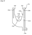
- FIG. 17 is a front view of the aperture blade 214.
- the aperture blade 214 is formed into a plate shape having a recess 214a formed so as to be incised.
- the aperture blade 214 has long guide holes 214b, 214c, and 214d and a connecting hole 214e.
- the shape and arrangement are similar to those of the guide holes 14b, 14c, and 14d and the connecting hole 14e according to the first embodiment.
- a pair of first edge portions 214f is formed similarly to the pair of first edge portions 14f.
- the recess 214a is provided between the guide holes 214b and 214c.
- the recess 214a includes a pair of second edge portions 214g, a pair of third edge portions 214h, and a fourth edge portion 214i.
- the second edge portions 214g as a pair are each formed linearly and have the same length, and each one end is connected to each end of the pair of first edge portions 214f.
- Each of the pair of second edge portions 214g is inclined at a predetermined angle with respect to the vertical direction so as to approach to each other as they approach to the other end.
- the third edge portions 214h as a pair are each formed linearly and have the same length, and each one end is connected to the other end of each of the pair of the second edge portions 214g.
- Each of the pair of third edge portions 214h is inclined at a predetermined angle with respect to the vertical direction so as to approach each other as they approach the other end.
- the inclination angle of the third edge portion 214h with respect to the vertical direction is larger than the inclination angle of the second edge portion 214g with respect to the vertical direction.
- the fourth edge portions 214i is formed extending in the horizontal direction, and the both ends are connected to the respective other ends of the third edge portions 214h as a pair.
- the recess 214a is formed symmetrically around a line passing through the midpoint of the fourth edge portion 214i and parallel to the vertical direction.
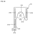
- FIG. 18 is a front view of the aperture blade 216.
- the aperture blade 216 is formed into a plate shape having a recess 216a formed so as to be incised.
- the aperture blade 216 has long guide holes 216b, 216c, and 216d and a connecting hole 216e.
- the shape and arrangement are similar to those of the guide holes 14b, 14c, and 14d and the connecting hole 14e according to the first embodiment.
- the first edge portion 216f is formed similarly to the pair of first edge portions 16f.
- the recess 216a is provided between the guide holes 216b and 216c.
- the recess 216a includes a pair of second edge portions 216g and the fourth edge portion 216i.
- the pair of second edge portions 216g its one end is connected to an end of the first edge portion 216f.
- the second edge portions 216g as a pair are each formed linearly, have the same length, and are inclined at a predetermined angle with respect to the vertical direction so as to approach to each other as they approach to the other end.
- the third edge portions 216h as a pair are each formed linearly and have the same length, and each one end is connected to the other end of each of the pair of the second edge portions 216g.
- Each of the pair of third edge portions 216h is inclined at a predetermined angle with respect to the vertical direction so as to approach to each other as they approach to the other end.
- the inclination angle of the third edge portion 216h with respect to the vertical direction is larger than the inclination angle of the second edge portion 216g with respect to the vertical direction.
- the fourth edge portion 216i is formed extending in the horizontal direction, and the both ends are connected to the respective other ends of the third edge portions 216h as a pair.
- the recess 216a is formed symmetrically around a line passing through the midpoint of the fourth edge portion 216i and parallel to the vertical direction.
- FIG. 19 is a front view of the aperture stop mechanism 10 when the two aperture blades 214 and 216 are attached to a base unit 12.
- a method of attaching the two aperture blades 214 and 216 to the base unit 12 is similar to the method of attaching the two aperture blades 14 and 16.
- the recesses 214a and 216a are opened to face each other.
- a single light passage opening 250 into which light utilized in imaging is introduced is constituted of both the recesses 214a and 216a as the respective edge portions of the two aperture blades 214 and 216.
- a drive mechanism 22 swings a swing rod 40 to thereby drive the two aperture blades 114 and 116 in directions opposite to each other in parallel with the vertical direction so that the aperture blades 114 and 116 are approached to and spaced apart from each other, so that the aperture area of the light passage opening 250 is changed.
- FIG. 20A is a view showing a method of determining the shape of the recess 214a.
- the pair of first edge portions 214f is formed so that an interval between the first edge portions 214f is the same as or slightly larger than a fixed aperture hole 20a.
- the pair of second edge portions 214g is formed so that the second edge portions 214g form 36°. Accordingly, the pair of second edge portions 214g is each inclined at 18° with respect to the vertical direction.
- the pair of second edge portions 214g is each provided at a position circumscribed with the fixed aperture hole 20a when the aperture blade 214 is located at the maximum aperture position.
- FIG. 20B is a view showing the method of determining the shape of the recess 214a.
- a virtual circle C1 having the aperture area for realizing the most frequently used F value is inscribed with the pair of second edge portions 214g determined in FIG. 20A .
- the pair of third edge portions 214h is formed so that the third edge portions 214h form 108°. Accordingly, the pair of third edge portions 214h is each inclined at 54° with respect to the vertical direction and formed so that the third edge portions 214h and the second edge portion 214g form an interior angle of 144°.
- the pair of third edge portions 214h is each formed to be circumscribed with the virtual circle C1.
- the fourth edge portion 214i is formed to be circumscribed with the virtual circle C1 while extending in the horizontal direction. Since the pair of third edge portions 214h and the fourth edge portion 214i are circumscribed with the same virtual circle C1 thus, the third edge portions 214h as a pair and the fourth edge portion 214i have the same length.
- each shape of the pair of first edge portions 214f, the pair of second edge portions 214g, the pair of third edge portions 214h, and the fourth edge portion 214i is determined.
- the recess 216a is formed into the same shape as the recess 214a except that the opening direction is opposite. Accordingly, the pair of second edge portions 216g is each inclined at 18° with respect to the vertical direction, the pair of third edge portions 216h is each inclined at 54° with respect to the vertical direction, and the fourth edge portion 216i is formed extending in the horizontal direction. The third edge portions 216h as a pair and the fourth edge portion 216i have the same length.
- the pair of second edge portions 216g is similar to the pair of second edge portions 214g in that the pair of second edge portions 216g is provided to be circumscribed with the fixed aperture hole 20a when the aperture blade 216 is located at the maximum aperture position.
- the recess 216a may be formed into a shape different from the recess 214a.
- FIGS. 21A to 21E are views showing a change of the shape of the light passage opening 250 when the two aperture blades 214 and 216 are approached to each other. For ease of understanding, each shape of the two aperture blades 214 and 216 is schematically shown.
- FIG. 21A is a front view of the aperture stop mechanism 10 when the two aperture blades 214 and 216 are located at the maximum aperture position to which the two aperture blades 214 and 216 move the most so that the light amount passing through the light passage opening 50 is maximum.
- the aperture area of the light passage opening 250 is the aperture area of the fixed aperture hole 20a.
- FIG. 21B is a front view of the aperture mechanism 10 when the two aperture blades 214 and 216 are approached to each other by a predetermined distance from the maximum aperture position.
- a portion of the pair of second edge portions 214g and a portion of the pair of the second edge portions 216g are located inside the fixed aperture hole 20a, and a part of light to be passed through the fixed aperture hole 20a is shielded.
- the third edge portion 214h, the fourth edge portion 214i, the third edge portion 216h, and the fourth edge portion 216i remain located outside the fixed aperture hole 20a.
- the light passage opening 50 at this time is defined by the pair of second edge portions 214g, the pair of second edge portions 216g, and the fixed aperture hole 20a.
- FIG. 21C is a front view of the aperture mechanism 10 when the two aperture blades 214 and 216 are further approached to each other by a predetermined distance from the state of FIG. 21B .
- the third edge portion 214h, the fourth edge portion 214i, the third edge portion 216h, and the fourth edge portion 216i are located inside the fixed aperture hole 20a.
- the third edge portion 214h, the fourth edge portion 214i, the third edge portion 216h, and the fourth edge portion 216i first enter inside the fixed aperture hole 20a, among the boundaries constituting the light passage opening 250, the boundaries constituted of the second edge portions 214g and the second edge portions 216g are longer than the third edge portion 214h and so on.
- the light passage opening 250 has a flat shape whose width in the vertical direction is larger than the width in the horizontal direction.
- FIG. 21D is a front view of the aperture mechanism 10 when the two aperture blades 214 and 216 are further approached to each other by a predetermined distance from the state of FIG. 21C .
- the flatness of the light passage opening 250 is gradually reduced, and the light passage opening 250 has a shape circumscribed with a virtual circle C1.
- the width in the vertical direction of the light passage opening 250 is the same as the width in the horizontal direction, and the flatness ratio is minimum.
- FIG. 21D shows the state at this time.
- the boundaries constituted of the second edge portion 214g and the second edge portion 216g have the same length as the third edge portion 214h and so on. Accordingly, in the light passage opening 250, ten edge portions constituting the boundary have the same length, and since the ten edge portions form 144° with the adj acent edge portions, the light passage opening 250 is a regular decagon.
- the regular decagon is formed to be circumscribed with the virtual circle C1.
- the light passage opening 250 can have the shape closest to the virtual circle C1. It will be understood that the shape of the light passage opening 250 at this time is not limited to the regular decagon, and the shape may be a decagon other than the regular decagon, for example.
- the two aperture blades 214 and 216 may be formed so that the light passage opening 250 has the shape closest to the virtual circle C1 for example when an F value larger than the most frequently used F value is realized.
- the two aperture blades 214 and 216 may be formed so that the light passage opening 250 has the shape closest to the virtual circle C1 when an F value smaller than the most frequently used F value is realized.
- FIG. 21E is a front view of the aperture stop mechanism 10 when the two aperture blades 214 and 216 are located at the minimum aperture position.
- the light passage opening 250 becomes flat so that the width in the horizontal direction is longer than the width in the vertical direction.
- the light passage opening 250 has a flat shape.
- the light passage opening 250 surrounded by the boundaries including ten straight lines is constituted of the edge portions of the two aperture blades 214 and 216.
- the boundaries of the light passage opening 250 are constituted of the ten straight lines when the two aperture blades 214 and 216 are located at the minimum aperture position, whereby it turns out that in comparison with a case where a diamond-shaped light passage opening is constituted of four straight lines, unnaturalness of a so-called blurred image of the background can be substantially reduced.
- the boundaries thereof may include not only straight lines but also curved lines.
- a connecting portion between the second edge portion 214g and the fourth edge portion 214i and a connecting portion between the second edge portion 216g and the fourth edge portion 216i may be curved lines.
- the drive mechanism 22 moves the two aperture blades 214 and 216 to the minimum aperture position and avoids further adjustment of the F value in the mechanical light amount adjustment means according to the aperture stop mechanism 200.
- the electronic control unit adj usts the storage time of the imaging device so as to substantially realize the F value set larger than the predetermined value.
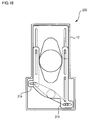
- FIG. 22 is a view showing the shape of the light passage opening 250 when the two aperture blades 214 and 216 are located at the minimum aperture position.
- the width in the vertical direction of the light passage opening 250 is minimum, and the width in the horizontal direction is maximum.
- the two aperture blades 214 and 216 are each formed so that the flatness ratio of the light passage opening 250 obtained by dividing a horizontal direction length L32 at this time by a vertical direction length L31 is more than 1 and not more than 1.4.
- the flatness ratio of the light passage opening 250 is set to such a value, whereby while unnaturalness of blur of the background is suppressed, smooth switching to the electronic shutter can be performed.
- the present invention is not limited to the above embodiments, and a suitable combination of the components of the above embodiments is effective as an embodiment of the present invention. Modifications such as various design changes may be added to each embodiment based on the knowledge of those skilled in the art, and the embodiment to which the modifications are added is also included in the range of the invention.
- two aperture blades are provided so as to form a single light passage opening, surrounded by boundaries including five or more straight lines, with the respective edge portions of the two aperture blades.
- the two aperture blades may be provided so as to form the single light passage opening, surrounded by boundaries including five straight lines, with the respective edge portions of the two aperture blades or may be provided so as to form the single light passage opening, surrounded by boundaries including seven straight lines, with the respective edge portions of the two aperture blades.
- the single light passage opening surrounded by boundaries including five or more straight lines is constituted of the respective edge portions of the two aperture blades, whereby in comparison with the case where a light passage opening surrounded by a diamond-shaped boundary comprising four straight lines, unnaturalness of a blurred image of the background can be suppressed.
- the two aperture blades may be provided so as to form the single light passage opening, surrounded by boundaries including five or more straight lines, with the respective edge portions of the two aperture blades when the two aperture blades are located at the minimum aperture position.
- the electronic control unit may adjust the amount of light utilized in imaging by adjusting the storage time of the imaging device.
- an ND (Neutral Density) filter is provided instead of an electronic shutter. Also in this case, the ND filter is provided so as to adjust the amount of light utilized in imaging when the two aperture blades are located at the minimum aperture position. Since the configuration of the ND filter is well-known, the description will be omitted. Even if the ND filter is used thus, the light amount can be adjusted when the two aperture blades are located at the minimum aperture position.
- Aperture stop mechanism 12 Base unit, 14 Aperture blade, 14a Recess, 14f First edge portion, 14g Second edge portion, 14h Third edge portion, 16 Aperture blade, 16a Recess, 16e Connecting hole, 16f First edge portion, 16g Second edge portion, 16h Third edge portion, 20 Base plate, 20a Fixed aperture hole, 22 Drive mechanism, 50 Light passage opening, 100 Aperture stop mechanism, 114 Aperture blade, 116 Aperture blade, 150 Light passage opening, 200 Aperture stop mechanism, 214 Aperture blade, 216 Aperture blade, 250 Light passage opening
- the present invention is available for an aperture stop mechanism, and available particularly for an aperture stop mechanism which drives two aperture blades and adjusts an aperture area of a light passage opening into which light for imaging is introduced.
Landscapes
- Physics & Mathematics (AREA)
- General Physics & Mathematics (AREA)
- Diaphragms For Cameras (AREA)
- Shutters For Cameras (AREA)
Abstract
Description
- The present invention relates to an aperture stop mechanism, and relates particularly to an aperture stop mechanism which drives two aperture blades and adjusts an aperture area of a light passage opening into which light for imaging is introduced.
- In the related art, there has been known an aperture stop mechanism which forms a light passage opening using two aperture blades and moves the two aperture blades in a direction of being approached to and spaced apart from each other to thereby adjust an aperture area of the light passage opening and, thus, to adjust light amount (for example, see Patent Literature 1 or 2). Further, there has been known a technique for minimizing the aperture area of the light passage opening and then adjusting exposure with an electronic shutter (for example, see Patent Literature 3).
-
- Patent Literature 1: Japanese Patent Application Laid-Open No.
2002-182264 - Patent Literature 2: Japanese Patent Application Laid-Open No.
2000-111970 - Patent Literature 3: Japanese Patent Application Laid-Open No.
8-237544 - In the aperture stop mechanisms described in the Patent Literature 1 or 2, when the aperture area of the light passage opening is reduced, the shape of the light passage opening is a diamond shape. If the shape of the light passage opening is a diamond shape, for example when photographing is performed so that the background is defocused to make a subject prominent, a blurred image of the background has a diamond shape, so that the background may become unnatural. Meanwhile, in order to avoid such a phenomenon, as described in the Patent Literature 3, there is considered a technique for switching to adjustment of exposure using an electronic shutter before the aperture area of the light passage opening is reduced so small. However, if the switching to the electronic shutter is performed before the aperture area of the light passage opening is reduced so small, strong light is applied to an imaging device, and this may cause influence on image quality such as smear.
- The present invention has been made in order to solve the above problem and it is therefore an object of the present invention to provide an aperture stop mechanism which suppresses unnaturalness of a blurred image of the background.
- In order to solve the above problem, an aperture stop mechanism in an embodiment of the present invention comprises two aperture blades and a drive mechanism. The two aperture blades are arranged so as to overlap each other and form a single light passage opening into which light utilized in imaging is introduced with the respective edge portions of the two aperture blades. The drive mechanism drives the two aperture blades in directions different from each other and thereby changes the aperture area of the light passage opening. The two aperture blades are provided so as to form the single light passage opening, surrounded by boundaries including five or more straight lines, with the respective edge portions of the two aperture blades.
- The present invention can provide an aperture stop mechanism which suppresses unnaturalness of a blurred image of the background.
-
-
FIG. 1 is a front view of an aperture stop mechanism according to a first embodiment; -
FIG. 2 is a front view of a base unit; -
FIG. 3 is a front view of an aperture blade; -
FIG. 4 is a front view of an aperture blade; -
FIG. 5 is a front view of the aperture stop mechanism when the two aperture blades are attached to the base unit; -
FIGS. 6A and 6B are views showing a method of determining a shape of a recess; -
FIGS. 7A to 7E are views showing a change of the shape of the light passage opening when the two aperture blades are approached to each other; -
FIG. 8 is a view showing the shape of the light passage opening when the two aperture blades are located at a minimum aperture position; -
FIG. 9 is a front view of an aperture stop mechanism according to a second embodiment; -
FIG. 10 is a front view of an aperture blade; -
FIG. 11 is a front view of an aperture blade; -
FIG. 12 is a front view of an aperture stop mechanism when the two aperture blades are attached to a base unit; -
FIGS. 13A and 13B are views showing a method of determining a shape of a recess; -
FIGS. 14A to 14E are views showing a change of a shape of a light passage opening when the two aperture blades are approached to each other; -
FIG. 15 is a view showing the shape of the light passage opening when the two aperture blades are located at the minimum aperture position; -
FIG. 16 is a front view of an aperture stop mechanism according to a third embodiment; -
FIG. 17 is a front view of an aperture blade; -
FIG. 18 is a front view of an aperture blade; -
FIG. 19 is a front view of the aperture stop mechanism when the two aperture blades are attached to a base unit; -
FIGS. 20A and 20B are views showing a method of determining a shape of a recess; -
FIGS. 21A to 21E are views showing a change of a shape of a light passage opening when the two aperture blades are approached to each other; and -
FIG. 22 is a view showing the shape of the light passage opening when the two aperture blades are located at the minimum aperture position. - Hereinafter, embodiments of the present invention (hereinafter referred to as embodiments) will be described in detail with reference to the drawings.
-
FIG. 1 is a front view of anaperture stop mechanism 10 according to the first embodiment. Theaperture stop mechanism 10 has abase unit 12 and twoaperture blades aperture blades FIG. 1 so as to be spaced apart from and approached to each other. Hereinafter, for ease of understanding, the direction in which each of the twoaperture blades aperture blades -
FIG. 2 is a front view of thebase unit 12. Thebase unit 12 has abase plate 20, adrive mechanism 22, andguide pins base plate 20 is formed into a substantially rectangular plate shape extending in the vertical direction, and an edge portion is vertically bent to provide a flange. Afixed aperture hole 20a which is a circular opening portion is provided at the substantially center of thebase plate 20. - The
drive mechanism 22 has aswing rod 40, aswing shaft 42, and connectingpins swing shaft 42 is attached near an end of theguide pin 30. The center of theswing rod 40 is swingably supported by theswing shaft 42. The connecting pins 44 and 46 are provided at the respective ends of theswing rod 40 so that the axial direction is vertical to thebase plate 20. - The guide pins 24, 26, 28, and 30 are each provided around the fixed
aperture hole 20a and arranged on thebase plate 20 so that the axial directions protrude so as to face perpendicular with respect to thebase plate 20. Specifically, the guide pins 24 and 26 and the guide pins 28 and 30 are respectively arranged to be aligned in the horizontal direction. The guide pins 28 and 30 are arranged at a position near thedrive mechanism 22 in comparison with the guide pins 24 and 26. The guide pins 24 and 28 are arranged to be aligned with the connectingpin 44 in the vertical direction. The guide pins 26 and 30 are arranged to be aligned with the connectingpin 46 in the vertical direction. -
FIG. 3 is a front view of theaperture blade 14. Theaperture blade 14 is formed into a plate shape having arecess 14a formed so as to be incised. Theaperture blade 14 haslong guide holes hole 14e. - The guide holes 14b, 14c, and 14d are each provided extending in the vertical direction. The guide holes 14b and 14d and the connecting
hole 14e are arranged to be aligned in the vertical direction in this order. The guide holes 14b and 14d are formed extending on the same straight line. The connectinghole 14e is formed extending in the horizontal direction. The guide holes 14c and 14b are formed to be aligned in the horizontal direction. - The
recess 14a is provided between the guide holes 14b and 14c. A pair offirst edge portions 14f is, at its one end, connected to therecess 14a and formed extending in parallel with the vertical direction. - The
recess 14a includes a pair ofsecond edge portions 14g and a pair ofthird edge portions 14h. Thesecond edge portions 14g as a pair are each formed linearly and have the same length. Each one end of the pair ofsecond edge portions 14g is connected to each one end of the pair offirst edge portions 14f extending in parallel with the vertical direction. Each of the pair ofsecond edge portions 14g is inclined at a predetermined angle with respect to the vertical direction so as to approach to each other as they approach to the other end. - The
third edge portions 14h as a pair are each formed linearly and have the same length, and each one end is connected to the other end of each of the pair ofsecond edge portions 14g. The other ends of thethird edge portions 14h as a pair are connected to each other. Each of the pair ofthird edge portions 14h is inclined at a predetermined angle with respect to the vertical direction so as to approach to each other as they approach to the other end. At this time, the inclination angle of thethird edge portion 14h with respect to the vertical direction is larger than the inclination angle of thesecond edge portion 14g with respect to the vertical direction. Thus, therecess 14a is formed symmetrically around a line passing through an intersection P1 of the pair ofthird edge portions 14h and parallel to the vertical direction. -
FIG. 4 is a front view of theaperture blade 16. Theaperture blade 16 is formed into a plate shape having arecess 16a formed so as to be incised. Theaperture blade 16 haslong guide holes hole 16e. - The guide holes 16b, 16c, and 16d are each provided extending in the vertical direction. The guide holes 16c and 16d and the connecting
hole 16e are formed to be aligned in the vertical direction in this order. The guide holes 16b and 16d are formed extending on the same straight line. The connectinghole 16e is formed extending in the horizontal direction. Theguide hole 16b is formed to be aligned with theguide hole 16c in the horizontal direction. - The
recess 16a is provided between the guide holes 16b and 16c. Therecess 16a includes a pair ofsecond edge portions 16g and a pair ofthird edge portions 16h. - The inside of the
guide hole 16d has a first edge portion 16f extending in the vertical direction. In one of the pair ofsecond edge portions 16g, its one end is connected to an end of the first edge portion 16f. Thesecond edge portions 16g as a pair are each formed linearly, have the same length, and are inclined at a predetermined angle with respect to the vertical direction so as to approach to each other as they approach to the other end. - The
third edge portions 16h as a pair are each formed linearly and have the same length, and each one end of thethird edge portions 16h is connected to the other end of each of the pair ofsecond edge portions 16g. In the pair ofthird edge portions 16h, the other ends are connected to each other. Each of the pair ofthird edge portions 16h is inclined at a predetermined angle with respect to the vertical direction so as to approach to each other as they approach to the other end. At this time, the inclination angle of thethird edge portion 16h with respect to the vertical direction is larger than the inclination angle of thesecond edge portion 16g with respect to the vertical direction. Thus, therecess 16a is formed symmetrically around a line passing through an intersection P2 of the pair ofthird edge portions 16h and parallel to the vertical direction. -
FIG. 5 is a front view of theaperture stop mechanism 10 when the twoaperture blades base unit 12. First, theaperture blade 16 is attached to thebase plate 20. At this time, theguide pin 24 is inserted into theguide hole 16b, theguide pin 26 is inserted into theguide hole 16c, and theguide pin 30 is inserted into theguide hole 16d. According to this constitution, theaperture blade 16 can be moved in the vertical direction, and the movement in the horizontal direction is limited. The connectingpin 46 of theswing rod 40 is inserted into the connectinghole 16e. - Next, the
aperture blade 14 is attached to thebase plate 20 so as to be superposed on theaperture blade 16. At this time, theguide pin 24 is inserted into theguide hole 14b, theguide pin 26 is inserted into theguide hole 14c, and theguide pin 28 is inserted into theguide hole 14d. According to this constitution, theaperture blade 14 can be moved in the vertical direction, and the movement in the horizontal direction is limited. The connectingpin 44 of theswing rod 40 is inserted into the connectinghole 14e. - When the two
aperture blades base unit 12, therecesses aperture blades light passage opening 50 into which light utilized for imaging is introduced is constituted of therecesses drive mechanism 22 swings theswing rod 40 to thereby drive the twoaperture blades aperture blades light passage opening 50 is changed. - The two
aperture blades drive mechanism 22 drives the twoaperture blades light passage opening 50 may be changed. - The
drive mechanism 22 drives the twoaperture blades light passage opening 50 is adjusted within a predetermined range. Specifically, thedrive mechanism 22 drives the twoaperture blades light passage opening 50 is minimum to a maximum aperture position where the aperture area of thelight passage opening 50 is maximum. -
FIG. 6A is a view showing a method of determining a shape of therecess 14a. The pair offirst edge portions 14f is formed so that an interval between thefirst edge portions 14f is the same as or slightly larger than the fixedaperture hole 20a. The pair ofsecond edge portions 14g is formed so that thesecond edge portions 14g form 45°. Accordingly, the pair ofsecond edge portions 14g is inclined at 22. 5° with respect to the vertical direction. The pair ofsecond edge portions 14g is provided at a position circumscribed with the fixedaperture hole 20a when theaperture blade 14 is located at the maximum aperture position. - As with
FIG. 6A, FIG. 6B is a view showing the method of determining the shape of therecess 14a. A virtual circle C1 having the aperture area for realizing the most frequently used F value is inscribed with the pair ofsecond edge portions 14g determined inFIG. 6A . In the first embodiment, the most frequently used F value is 4. It will be understood that the F value at this time is not limited to 4. - The pair of
third edge portions 14h is formed so that the third edge portions form an interior angle of 135°. Accordingly, the pair ofthird edge portions 14h is inclined at 67.5° with respect to the vertical direction and formed so that thethird edge portions 14h and thesecond edge portions 14g form an interior angle of 135°. The pair ofthird edge portions 14h is formed to be circumscribed with the virtual circle C1. Thus, each shape of the pair offirst edge portions 14f, the pair ofsecond edge portions 14g, and the pair ofthird edge portions 14h is determined. - The
recess 16a is formed into the same shape as therecess 14a except that the opening direction is opposite. Accordingly, the pair ofsecond edge portions 16g is inclined at 22. 5° with respect to the vertical direction, and the pair ofthird edge portions 16h is inclined at 67. 5° with respect to the vertical direction. The pair ofsecond edge portions 16g is similar to the pair ofsecond edge portions 14g in that the pair ofsecond edge portions 16g is provided to be circumscribed with the fixedaperture hole 20a when theaperture blade 16 is located at the maximum aperture position. Therecess 16a may be formed into a shape different from therecess 14a. -
FIGS. 7A to 7E are views showing a change of the shape of thelight passage opening 50 when the twoaperture blades aperture blades -
FIG. 7A is a front view of theaperture stop mechanism 10 when the twoaperture blades aperture blades light passage opening 50 is maximum. When the twoaperture blades aperture hole 20a according to the twoaperture blades light passage opening 50 is the aperture area of the fixedaperture hole 20a. -
FIG. 7B is a front view of theaperture mechanism 10 when each of the twoaperture blades second edge portions 14g and a portion of the pair ofsecond edge portions 16g are located inside the fixedaperture hole 20a, and a part of light to be passed through the fixedaperture hole 20a is shielded. However, the pair ofthird edge portions 14h and the pair ofthird edge portions 16h remain located outside the fixedaperture hole 20a. Thus, the light passage opening 50 at this time is defined by the pair ofsecond edge portions 14g, the pair of thesecond edge portions 16g, and the fixedaperture hole 20a. -
FIG. 7C is a front view of theaperture mechanism 10 when each of the twoaperture blades FIG. 7B . At this time, the pair ofthird edge portions 14h and the pair ofthird edge portions 16h are located inside the fixedaperture hole 20a. However, when the pair ofthird edge portions 14h and the pair of thethird edge portions 16h first enter inside the fixedaperture hole 20a, among the boundaries constituting thelight passage opening 50, the boundaries constituted of thesecond edge portions 14g and thesecond edge portions 16g are longer than thethird edge portion 14h and thethird edge portion 16h. Thus, thelight passage opening 50 has a flat shape whose width in the vertical direction is larger than the width in the horizontal direction. -
FIG. 7D is a front view of theaperture mechanism 10 when each of the twoaperture blades FIG. 7C . When the twoaperture blades light passage opening 50 is gradually reduced, and the width in the vertical direction is equal to the width in the horizontal direction.FIG. 7D shows the state at this time. - At this time, among the boundaries constituting the
light passage opening 50, the boundaries constituted of thesecond edge portion 14g and thesecond edge portion 16g have the same length as thethird edge portion 14h and thethird edge portion 16h. Accordingly, in thelight passage opening 50, eight edge portions constituting the boundary have the same length, and since the eight edge portions form 135° with the adjacent edge portions, thelight passage opening 50 is a regular octagon. The regular octagon is formed to be circumscribed with the virtual circle C1. - When the most frequently used F value is realized thus, the
light passage opening 50 can have the shape closest to the virtual circle C1. It will be understood that the shape of the light passage opening 50 at this time is not limited to the regular octagon, and the shape may be an octagon other than the regular octagon, for example. - If the boundaries constituting the
light passage opening 50 are constituted of curved lines, especially when outside is bright, an influence on image quality called "ghost" easily occurs. The boundaries of thelight passage opening 50 are constituted thus, whereby the ghost can be suppressed. - The two
aperture blades light passage opening 50 has the shape closest to the virtual circle C1 for example when an F value larger than the most frequently used F value is realized. According to this constitution, the flatness of thelight passage opening 50 can be reduced when outside is bright, and the influence on image quality due to the flatness of thelight passage opening 50 can be suppressed. The twoaperture blades light passage opening 50 has the shape closest to the virtual circle C1 when an F value smaller than the most frequently used F value is realized. -
FIG. 7E is a front view of theaperture stop mechanism 10 when the twoaperture blades aperture blades FIG. 7D , thelight passage opening 50 becomes flat so that the width in the horizontal direction is longer than the width in the vertical direction. Even when the twoaperture blades light passage opening 50 has a flat shape. Even when the twoaperture blades aperture blades - For example when the light passage opening has a diamond shape surrounded by four straight lines, a blurred image of the background has a diamond shape for example when photographing is performed so that the background is defocused to make a subject prominent, so that the background image may become unnatural. As a result of the experiment performed by the inventor of the present invention, the boundaries of the
light passage opening 50 are constituted of the eight straight lines when the twoaperture blades aperture stop mechanism 10, the unnaturalness of the blurred image of the background and the ghost can be suitably suppressed. - In the
light passage opening 50, the boundaries thereof may include not only straight lines but also curved lines. For example, a connecting portion of the pair ofthird edge portions 14h and a connecting portion of the pair ofthird edge portions 16h may be curved lines. Further, a connecting portion between thesecond edge portion 14g and thethird edge portions 14h and a connecting portion between thesecond edge portion 16g and thethird edge portions 16h may be curved lines. - In the first embodiment, when the F value to be realized is not more than a predetermined value, the
drive mechanism 22 moves the twoaperture blades - An imaging apparatus such as a camera and a video mounted with the
aperture stop mechanism 10 comprises an imaging device (not shown) such as a CCD (Charge Coupled Device) image sensor and a CMOS (Complementary Metal Oxide Semiconductor) image sensor and an electronic control unit (not shown) which adjusts storage time for exposing the imaging device to store electricity. The electronic control unit is constituted of microcomputer, ROM, RAM, and so on. The electronic control unit adjusts the storage time of the imaging device thus and thereby substantially adjusts the amount of light passing through thelight passage opening 50 and utilized for imaging. Thus, the electronic control unit functions as light amount adjustment means. Such an exposure adjustment according to control of the imaging device is called an "electronic shutter". The imaging apparatus mounted with theaperture stop mechanism 10 has mechanical light amount adjustment means according to theaperture stop mechanism 10 and the electronic shutter. - The electronic control unit detects brightness of outside utilizing a detection signal from the imaging device. The electronic control unit sets the F value to be realized utilizing the detected brightness of outside. When the set F value is not more than a predetermined value, the
drive mechanism 22 drives the twoaperture blades aperture stop mechanism 10. When the set F value is larger than the predetermined value, thedrive mechanism 22 moves the twoaperture blades aperture stop mechanism 10. At this time, the electronic control unit adjusts the storage time of the imaging device so as to substantially realize the F value set larger than the predetermined value. Theaperture stop mechanism 10 as the mechanical light amount adjustment means and the electronic shutter are used in combination, whereby this constitution can correspond to a large F value while suppressing the flatness ratio of the light passage opening 50 at the minimum aperture position. -
FIG. 8 is a view showing the shape of thelight passage opening 50 when the twoaperture blades light passage opening 50 is maximum. The twoaperture blades light passage opening 50 obtained by dividing a horizontal direction length L12 at this time by a vertical direction length L11 is more than 1 and not more than 1.4. As a result of the experiment performed by the inventor of the present invention, the flatness ratio of thelight passage opening 50 is set to such a value when the twoaperture blades -
FIG. 9 is a front view of anaperture stop mechanism 100 according to the second embodiment. Unless particularly referred to, the configurations of theaperture stop mechanism 100 and an imaging apparatus mounted with theaperture stop mechanism 100 are similar to those of the first embodiment. Hereinafter, components similar to those in the first embodiment are denoted by the same reference numerals, and descriptions thereof are omitted. - The
aperture stop mechanism 100 has abase unit 12 and twoaperture blades aperture blades -
FIG. 10 is a front view of anaperture blade 114. Theaperture blade 114 is formed into a plate shape having arecess 114a formed so as to be incised. Theaperture blade 114 haslong guide holes hole 114e. However, the shape and arrangement are similar to those of the guide holes 14b, 14c, and 14d and the connectinghole 14e according to the first embodiment. A pair offirst edge portions 114f is formed similarly to the pair offirst edge portions 14f. - The
recess 114a is provided between the guide holes 114b and 114c. Therecess 114a includes a pair ofsecond edge portions 114g and a pair ofthird edge portions 114h. Thesecond edge portions 114g as a pair are each formed linearly and have the same length, and each one end is connected to each of the pair offirst edge portions 114f. Each of the pair ofsecond edge portions 114g is inclined at a predetermined angle with respect to the vertical direction so as to approach to each other as they approach the other end. Thethird edge portion 114h is formed extending in the horizontal direction, and the both ends are connected to the respective other ends of thesecond edge portions 114g as a pair. Thus, therecess 114a is formed symmetrically around a line passing through the midpoint of thethird edge portion 114h and parallel to the vertical direction. -
FIG. 11 is a front view of theaperture blade 116. Theaperture blade 116 is formed into a plate shape having arecess 116a formed so as to be incised. Theaperture blade 116 haslong guide holes hole 116e. The shape and arrangement of the guide holes 116b, 116c, 116d and the connectinghole 116e are similar to those of the guide holes 14b, 14c, and 14d and the connectinghole 14e according to the first embodiment. Thefirst edge portion 116f is formed similarly to the pair of first edge portions 16f. - The
recess 116a is provided between the guide holes 116b and 116c. Therecess 116a includes a pair ofsecond edge portions 116g and athird edge portion 116h. - In one of the pair of
second edge portions 116g, its one end is connected to an end of thefirst edge portion 116f. Thesecond edge portions 116g as a pair are formed linearly, have the same length, and are inclined at a predetermined angle with respect to the vertical direction so as to approach to each other as they approach the other end. Thethird edge portion 116h is formed extending in the horizontal direction, and the both ends are connected to the respective other ends of thesecond edge portions 116g as a pair. Thus, therecess 116a is formed symmetrically around a line passing through the midpoint of thethird edge portion 116h and parallel to the vertical direction. -
FIG. 12 is a front view of theaperture stop mechanism 10 when the twoaperture blades base unit 12. A method of attaching the twoaperture blades base unit 12 is similar to the method of attaching the twoaperture blades aperture blades base unit 12, therecesses aperture blades light passage opening 150 into which light utilized in imaging is introduced is constituted of both therecesses aperture blades drive mechanism 22 swings aswing rod 40 to thereby drive the twoaperture blades aperture blades light passage opening 150 is changed. -
FIG. 13A is a view showing a method of determining the shape of therecess 114a. The pair offirst edge portions 114f is formed so that an interval between thefirst edge portions 114f is the same as or slightly larger than a fixedaperture hole 20a. The pair ofsecond edge portions 114g is formed so that thesecond edge portions 114g form 60°. Accordingly, the pair ofsecond edge portions 114g is each inclined at 30° with respect to the vertical direction. The pair ofsecond edge portions 114g is each provided at a position circumscribed with the fixedaperture hole 20a when theaperture blade 114 is located at the maximum aperture position. - As with
FIG. 13A, FIG. 13B is a view showing the method of determining the shape of therecess 114a. A virtual circle C1 having the aperture area for realizing the most frequently used F value is inscribed with the pair ofsecond edge portions 114g determined inFIG. 13A . - The
third edge portion 114h is formed to be circumscribed with the virtual circle C1 while extending in the horizontal direction. Thus, each shape of the pair offirst edge portions 114f, the pair ofsecond edge portions 114g, and the pair ofthird edge portions 114h is determined. - The
recess 116a is formed into the same shape as therecess 114a except that the opening direction is opposite. Accordingly, the pair ofsecond edge portions 116g is inclined at 30° with respect to the vertical direction, and thethird edge portion 116h is formed extending in the horizontal direction. The pair ofsecond edge portions 116g is similar to the pair ofsecond edge portions 114g in that the pair ofsecond edge portions 116g is provided to be circumscribed with the fixedaperture hole 20a when theaperture blade 116 is located at the maximum aperture position. Therecess 116a may be formed into a shape different from therecess 114a. -
FIGS. 14A to 14E are views showing a change of the shape of thelight passage opening 150 when the twoaperture blades aperture blades -
FIG. 14A is a front view of theaperture stop mechanism 10 when the twoaperture blades aperture blades light passage opening 50 is maximum. When the twoaperture blades aperture hole 20a according to the twoaperture blades light passage opening 150 is the aperture area of the fixedaperture hole 20a. -
FIG. 14B is a front view of theaperture mechanism 10 when the twoaperture blades second edge portions 114g and a portion of the pair of thesecond edge portions 116g are located inside the fixedaperture hole 20a, and a part of light to be passed through the fixedaperture hole 20a is shielded. However, thethird edge portion 114h and thethird edge portion 116h remain located outside the fixedaperture hole 20a. Thus, the light passage opening 50 at this time is defined by the pair ofsecond edge portions 114g, the pair of thesecond edge portions 116g, and the fixedaperture hole 20a. -
FIG. 14C is a front view of theaperture mechanism 10 when the twoaperture blades FIG. 14B . At this time, thethird edge portion 114h and thethird edge portion 116h are located inside the fixedaperture hole 20a. However, when thethird edge portion 114h and thethird edge portion 116h first enter inside the fixedaperture hole 20a, among the boundaries constituting thelight passage opening 150, the boundaries constituted of thesecond edge portions 114g and thesecond edge portions 116g are longer than thethird edge portion 114h and thethird edge portion 116h. Thus, thelight passage opening 150 has a flat shape whose width in the vertical direction is larger than the width in the horizontal direction. -
FIG. 14D is a front view of theaperture mechanism 10 when the twoaperture blades FIG. 14C . When the twoaperture blades light passage opening 150 is gradually reduced, and thelight passage opening 150 has a shape circumscribed with a virtual circle C1.FIG. 14D shows the state at this time. - At this time, among the boundaries constituting the
light passage opening 150, the boundaries constituted of thesecond edge portion 114g and thesecond edge portion 116g have the same length as thethird edge portion 114h and thethird edge portion 116h. Accordingly, in thelight passage opening 150, six edge portions constituting the boundary have the same length, and since the six edge portions form 120° with the adjacent edge portions, thelight passage opening 150 is a regular hexagon. The regular hexagon is formed to be circumscribed with the virtual circle C1. - When the most frequently used F value is realized thus, the
light passage opening 150 can have the shape closest to the virtual circle C1. It will be understood that the shape of thelight passage opening 150 at this time is not limited to the regular hexagon, and the shape may be a hexagon other than the regular hexagon, for example. - The two
aperture blades light passage opening 150 has the shape closest to the virtual circle C1 when an F value larger than the most frequently used F value is realized, for example. The twoaperture blades light passage opening 150 has the shape closest to the virtual circle C1 when an F value smaller than the most frequently used F value is realized. -
FIG. 14E is a front view of theaperture stop mechanism 10 when the twoaperture blades aperture blades FIG. 14D , thelight passage opening 150 becomes flat so that the width in the horizontal direction is longer than the width in the vertical direction. When the twoaperture blades light passage opening 150 has a flat shape. - The two
aperture blades light passage opening 150, surrounded by the boundaries including six straight lines, with the edge portions of the twoaperture blades aperture blades light passage opening 150 are constituted of the six straight lines when the twoaperture blades - In the
light passage opening 150, the boundaries thereof may include not only straight lines but also curved lines. For example, a connecting portion between thesecond edge portion 114g and thethird edge portions 114h and a connecting portion between thesecond edge portion 116g and thethird edge portions 116h may be curved lines. - Even in the second embodiment, when the set F value is larger than the predetermined value, the
drive mechanism 22 moves the twoaperture blades aperture stop mechanism 100. At this time, the electronic control unit adjusts the storage time of the imaging device so as to substantially realize the F value set larger than the predetermined value. -
FIG. 15 is a view showing the shape of thelight passage opening 150 when the twoaperture blades light passage opening 150 is minimum, and the width in the horizontal direction is maximum. The twoaperture blades light passage opening 150 obtained by dividing a horizontal direction length L22 at this time by a vertical direction length L21 is more than 1 and not more than 1.4. The flatness ratio of thelight passage opening 150 is set to such a value, whereby while unnaturalness of blur of the background is suppressed, smooth switching to the electronic shutter can be performed. -
FIG. 16 is a front view of anaperture stop mechanism 200 according to the third embodiment. Unless particularly referred to, the configurations of theaperture stop mechanism 200 and an imaging apparatus mounted with theaperture stop mechanism 200 are similar to those of the first embodiment. Hereinafter, components similar to those in the above embodiments are denoted by the same reference numerals, and descriptions thereof are omitted. - The
aperture stop mechanism 200 has abase unit 12 and twoaperture blades aperture blades -
FIG. 17 is a front view of theaperture blade 214. Theaperture blade 214 is formed into a plate shape having arecess 214a formed so as to be incised. Theaperture blade 214 haslong guide holes hole 214e. However, the shape and arrangement are similar to those of the guide holes 14b, 14c, and 14d and the connectinghole 14e according to the first embodiment. A pair offirst edge portions 214f is formed similarly to the pair offirst edge portions 14f. - The
recess 214a is provided between the guide holes 214b and 214c. Therecess 214a includes a pair ofsecond edge portions 214g, a pair ofthird edge portions 214h, and afourth edge portion 214i. - The
second edge portions 214g as a pair are each formed linearly and have the same length, and each one end is connected to each end of the pair offirst edge portions 214f. Each of the pair ofsecond edge portions 214g is inclined at a predetermined angle with respect to the vertical direction so as to approach to each other as they approach to the other end. Thethird edge portions 214h as a pair are each formed linearly and have the same length, and each one end is connected to the other end of each of the pair of thesecond edge portions 214g. Each of the pair ofthird edge portions 214h is inclined at a predetermined angle with respect to the vertical direction so as to approach each other as they approach the other end. At this time, the inclination angle of thethird edge portion 214h with respect to the vertical direction is larger than the inclination angle of thesecond edge portion 214g with respect to the vertical direction. Thefourth edge portions 214i is formed extending in the horizontal direction, and the both ends are connected to the respective other ends of thethird edge portions 214h as a pair. Thus, therecess 214a is formed symmetrically around a line passing through the midpoint of thefourth edge portion 214i and parallel to the vertical direction. -
FIG. 18 is a front view of theaperture blade 216. Theaperture blade 216 is formed into a plate shape having arecess 216a formed so as to be incised. Theaperture blade 216 haslong guide holes hole 216e. However, the shape and arrangement are similar to those of the guide holes 14b, 14c, and 14d and the connectinghole 14e according to the first embodiment. Thefirst edge portion 216f is formed similarly to the pair of first edge portions 16f. - The
recess 216a is provided between the guide holes 216b and 216c. Therecess 216a includes a pair ofsecond edge portions 216g and thefourth edge portion 216i. - In one of the pair of
second edge portions 216g, its one end is connected to an end of thefirst edge portion 216f. Thesecond edge portions 216g as a pair are each formed linearly, have the same length, and are inclined at a predetermined angle with respect to the vertical direction so as to approach to each other as they approach to the other end. Thethird edge portions 216h as a pair are each formed linearly and have the same length, and each one end is connected to the other end of each of the pair of thesecond edge portions 216g. Each of the pair ofthird edge portions 216h is inclined at a predetermined angle with respect to the vertical direction so as to approach to each other as they approach to the other end. At this time, the inclination angle of thethird edge portion 216h with respect to the vertical direction is larger than the inclination angle of thesecond edge portion 216g with respect to the vertical direction. Thefourth edge portion 216i is formed extending in the horizontal direction, and the both ends are connected to the respective other ends of thethird edge portions 216h as a pair. Thus, therecess 216a is formed symmetrically around a line passing through the midpoint of thefourth edge portion 216i and parallel to the vertical direction. -
FIG. 19 is a front view of theaperture stop mechanism 10 when the twoaperture blades base unit 12. A method of attaching the twoaperture blades base unit 12 is similar to the method of attaching the twoaperture blades aperture blades base unit 12, therecesses aperture blades light passage opening 250 into which light utilized in imaging is introduced is constituted of both therecesses aperture blades drive mechanism 22 swings aswing rod 40 to thereby drive the twoaperture blades aperture blades light passage opening 250 is changed. -
FIG. 20A is a view showing a method of determining the shape of therecess 214a. The pair offirst edge portions 214f is formed so that an interval between thefirst edge portions 214f is the same as or slightly larger than a fixedaperture hole 20a. The pair ofsecond edge portions 214g is formed so that thesecond edge portions 214g form 36°. Accordingly, the pair ofsecond edge portions 214g is each inclined at 18° with respect to the vertical direction. The pair ofsecond edge portions 214g is each provided at a position circumscribed with the fixedaperture hole 20a when theaperture blade 214 is located at the maximum aperture position. - As with
FIG. 20A, FIG. 20B is a view showing the method of determining the shape of therecess 214a. A virtual circle C1 having the aperture area for realizing the most frequently used F value is inscribed with the pair ofsecond edge portions 214g determined inFIG. 20A . - The pair of
third edge portions 214h is formed so that thethird edge portions 214h form 108°. Accordingly, the pair ofthird edge portions 214h is each inclined at 54° with respect to the vertical direction and formed so that thethird edge portions 214h and thesecond edge portion 214g form an interior angle of 144°. The pair ofthird edge portions 214h is each formed to be circumscribed with the virtual circle C1. Thefourth edge portion 214i is formed to be circumscribed with the virtual circle C1 while extending in the horizontal direction. Since the pair ofthird edge portions 214h and thefourth edge portion 214i are circumscribed with the same virtual circle C1 thus, thethird edge portions 214h as a pair and thefourth edge portion 214i have the same length. Thus, each shape of the pair offirst edge portions 214f, the pair ofsecond edge portions 214g, the pair ofthird edge portions 214h, and thefourth edge portion 214i is determined. - The
recess 216a is formed into the same shape as therecess 214a except that the opening direction is opposite. Accordingly, the pair ofsecond edge portions 216g is each inclined at 18° with respect to the vertical direction, the pair ofthird edge portions 216h is each inclined at 54° with respect to the vertical direction, and thefourth edge portion 216i is formed extending in the horizontal direction. Thethird edge portions 216h as a pair and thefourth edge portion 216i have the same length. The pair ofsecond edge portions 216g is similar to the pair ofsecond edge portions 214g in that the pair ofsecond edge portions 216g is provided to be circumscribed with the fixedaperture hole 20a when theaperture blade 216 is located at the maximum aperture position. Therecess 216a may be formed into a shape different from therecess 214a. -
FIGS. 21A to 21E are views showing a change of the shape of thelight passage opening 250 when the twoaperture blades aperture blades -
FIG. 21A is a front view of theaperture stop mechanism 10 when the twoaperture blades aperture blades light passage opening 50 is maximum. When the twoaperture blades aperture hole 20a according to the twoaperture blades light passage opening 250 is the aperture area of the fixedaperture hole 20a. -
FIG. 21B is a front view of theaperture mechanism 10 when the twoaperture blades second edge portions 214g and a portion of the pair of thesecond edge portions 216g are located inside the fixedaperture hole 20a, and a part of light to be passed through the fixedaperture hole 20a is shielded. However, thethird edge portion 214h, thefourth edge portion 214i, thethird edge portion 216h, and thefourth edge portion 216i remain located outside the fixedaperture hole 20a. Thus, the light passage opening 50 at this time is defined by the pair ofsecond edge portions 214g, the pair ofsecond edge portions 216g, and the fixedaperture hole 20a. -
FIG. 21C is a front view of theaperture mechanism 10 when the twoaperture blades FIG. 21B . At this time, thethird edge portion 214h, thefourth edge portion 214i, thethird edge portion 216h, and thefourth edge portion 216i are located inside the fixedaperture hole 20a. However, when thethird edge portion 214h, thefourth edge portion 214i, thethird edge portion 216h, and thefourth edge portion 216i first enter inside the fixedaperture hole 20a, among the boundaries constituting thelight passage opening 250, the boundaries constituted of thesecond edge portions 214g and thesecond edge portions 216g are longer than thethird edge portion 214h and so on. Thus, thelight passage opening 250 has a flat shape whose width in the vertical direction is larger than the width in the horizontal direction. -
FIG. 21D is a front view of theaperture mechanism 10 when the twoaperture blades FIG. 21C . When the twoaperture blades light passage opening 250 is gradually reduced, and thelight passage opening 250 has a shape circumscribed with a virtual circle C1. At this time, the width in the vertical direction of thelight passage opening 250 is the same as the width in the horizontal direction, and the flatness ratio is minimum.FIG. 21D shows the state at this time. - At this time, among the boundaries constituting the
light passage opening 250, the boundaries constituted of thesecond edge portion 214g and thesecond edge portion 216g have the same length as thethird edge portion 214h and so on. Accordingly, in thelight passage opening 250, ten edge portions constituting the boundary have the same length, and since the ten edge portions form 144° with the adj acent edge portions, thelight passage opening 250 is a regular decagon. The regular decagon is formed to be circumscribed with the virtual circle C1. - When the most frequently used F value is realized thus, the
light passage opening 250 can have the shape closest to the virtual circle C1. It will be understood that the shape of thelight passage opening 250 at this time is not limited to the regular decagon, and the shape may be a decagon other than the regular decagon, for example. - The two
aperture blades light passage opening 250 has the shape closest to the virtual circle C1 for example when an F value larger than the most frequently used F value is realized. The twoaperture blades light passage opening 250 has the shape closest to the virtual circle C1 when an F value smaller than the most frequently used F value is realized. -
FIG. 21E is a front view of theaperture stop mechanism 10 when the twoaperture blades aperture blades FIG. 21D , thelight passage opening 250 becomes flat so that the width in the horizontal direction is longer than the width in the vertical direction. When the twoaperture blades light passage opening 250 has a flat shape. - Even when the two
aperture blades light passage opening 250 surrounded by the boundaries including ten straight lines is constituted of the edge portions of the twoaperture blades light passage opening 250 are constituted of the ten straight lines when the twoaperture blades - In the
light passage opening 250, the boundaries thereof may include not only straight lines but also curved lines. For example, a connecting portion between thesecond edge portion 214g and thefourth edge portion 214i and a connecting portion between thesecond edge portion 216g and thefourth edge portion 216i may be curved lines. - Even in the third embodiment, when the set F value is larger than the predetermined value, the
drive mechanism 22 moves the twoaperture blades aperture stop mechanism 200. At this time, the electronic control unit adj usts the storage time of the imaging device so as to substantially realize the F value set larger than the predetermined value. -
FIG. 22 is a view showing the shape of thelight passage opening 250 when the twoaperture blades light passage opening 250 is minimum, and the width in the horizontal direction is maximum. The twoaperture blades light passage opening 250 obtained by dividing a horizontal direction length L32 at this time by a vertical direction length L31 is more than 1 and not more than 1.4. The flatness ratio of thelight passage opening 250 is set to such a value, whereby while unnaturalness of blur of the background is suppressed, smooth switching to the electronic shutter can be performed. - The present invention is not limited to the above embodiments, and a suitable combination of the components of the above embodiments is effective as an embodiment of the present invention. Modifications such as various design changes may be added to each embodiment based on the knowledge of those skilled in the art, and the embodiment to which the modifications are added is also included in the range of the invention.
- In a certain variation, two aperture blades are provided so as to form a single light passage opening, surrounded by boundaries including five or more straight lines, with the respective edge portions of the two aperture blades. For example, the two aperture blades may be provided so as to form the single light passage opening, surrounded by boundaries including five straight lines, with the respective edge portions of the two aperture blades or may be provided so as to form the single light passage opening, surrounded by boundaries including seven straight lines, with the respective edge portions of the two aperture blades. The single light passage opening surrounded by boundaries including five or more straight lines is constituted of the respective edge portions of the two aperture blades, whereby in comparison with the case where a light passage opening surrounded by a diamond-shaped boundary comprising four straight lines, unnaturalness of a blurred image of the background can be suppressed.
- Also in this case, the two aperture blades may be provided so as to form the single light passage opening, surrounded by boundaries including five or more straight lines, with the respective edge portions of the two aperture blades when the two aperture blades are located at the minimum aperture position. When the two aperture blades are located at the minimum aperture position, the electronic control unit may adjust the amount of light utilized in imaging by adjusting the storage time of the imaging device.
- In another variation, an ND (Neutral Density) filter is provided instead of an electronic shutter. Also in this case, the ND filter is provided so as to adjust the amount of light utilized in imaging when the two aperture blades are located at the minimum aperture position. Since the configuration of the ND filter is well-known, the description will be omitted. Even if the ND filter is used thus, the light amount can be adjusted when the two aperture blades are located at the minimum aperture position.
- 10 Aperture stop mechanism, 12 Base unit, 14 Aperture blade, 14a Recess, 14f First edge portion, 14g Second edge portion, 14h Third edge portion, 16 Aperture blade, 16a Recess, 16e Connecting hole, 16f First edge portion, 16g Second edge portion, 16h Third edge portion, 20 Base plate, 20a Fixed aperture hole, 22 Drive mechanism, 50 Light passage opening, 100 Aperture stop mechanism, 114 Aperture blade, 116 Aperture blade, 150 Light passage opening, 200 Aperture stop mechanism, 214 Aperture blade, 216 Aperture blade, 250 Light passage opening
- The present invention is available for an aperture stop mechanism, and available particularly for an aperture stop mechanism which drives two aperture blades and adjusts an aperture area of a light passage opening into which light for imaging is introduced.
Claims (6)
- An aperture stop mechanism comprising:two aperture blades operative to be arranged so as to overlap each other and form a single light passage opening, into which light utilized in imaging is introduced, with the respective edge portions of the two aperture blades; anda drive mechanism operative to drive the two aperture blades in directions different from each other and thereby change an aperture area of the light passage opening, whereinthe two aperture blades are provided so as to form the single light passage opening, surrounded by boundaries including five or more straight lines, with the respective edge portions of the two aperture blades.
- The aperture stop mechanism according to claim 1, wherein the two aperture blades are provided so as to form a single light passage opening, surrounded by boundaries including six, eight, or ten straight lines, with the respective edge portions of the two aperture blades.
- The aperture stop mechanism according to claim 1, wherein
the two aperture blades form a single light passage opening, surrounded by boundaries including n (n = 6, 8, 10) straight lines, with the respective edge portions of the two aperture blades and, at the same time, are provided so that the light passage opening is a regular n-polygon at a predetermined proximate position between the two aperture blades. - The aperture stop mechanism according to any one of claims 1 to 3, wherein
the drive mechanism drives the two aperture blades so as to adjust an aperture area of the light passage opening within a predetermined range, the two aperture blades are provided so as to form a single light passage opening, surrounded by boundaries including five or more straight lines, with the respective edge portions of the two aperture blades when the two aperture blades are located at a minimum aperture position where the aperture area of the light passage opening is minimum within the predetermined range. - The aperture stop mechanism according to claim 4, further comprising light amount adjustment means operative to adjust an amount of light passing through the light passage opening and utilized in imaging, the light amount adjustment means adjusting the amount of light utilized in imaging when the two aperture blades are located at the minimum aperture position.
- The aperture stop mechanism according to claim 4, wherein
the two aperture blades are provided so that when the two aperture blades are located at the minimum aperture position, a flatness ratio obtained by dividing the maximum width of the light passage opening by a width in a direction perpendicular to the direction of the maximum width is more than 1 and not more than 1.4.
Applications Claiming Priority (2)
| Application Number | Priority Date | Filing Date | Title |
|---|---|---|---|
| JP2009270459A JP2011112946A (en) | 2009-11-27 | 2009-11-27 | Diaphragm mechanism |
| PCT/JP2010/006923 WO2011065017A1 (en) | 2009-11-27 | 2010-11-26 | Aperture mechanism |
Publications (3)
| Publication Number | Publication Date |
|---|---|
| EP2506072A1 true EP2506072A1 (en) | 2012-10-03 |
| EP2506072A4 EP2506072A4 (en) | 2016-03-16 |
| EP2506072B1 EP2506072B1 (en) | 2018-02-28 |
Family
ID=44066122
Family Applications (1)
| Application Number | Title | Priority Date | Filing Date |
|---|---|---|---|
| EP10832866.7A Active EP2506072B1 (en) | 2009-11-27 | 2010-11-26 | Aperture mechanism |
Country Status (5)
| Country | Link |
|---|---|
| US (1) | US8657510B2 (en) |
| EP (1) | EP2506072B1 (en) |
| JP (1) | JP2011112946A (en) |
| CN (1) | CN102667607A (en) |
| WO (1) | WO2011065017A1 (en) |
Cited By (2)
| Publication number | Priority date | Publication date | Assignee | Title |
|---|---|---|---|---|
| US10809595B2 (en) | 2015-02-27 | 2020-10-20 | Nidec Copal Corporation | Blade driving device |
| EP4506752A1 (en) | 2023-08-09 | 2025-02-12 | Yuk Sum Chan | Aperture stop mechanism and lens module |
Families Citing this family (12)
| Publication number | Priority date | Publication date | Assignee | Title |
|---|---|---|---|---|
| JP2011112946A (en) * | 2009-11-27 | 2011-06-09 | Victor Co Of Japan Ltd | Diaphragm mechanism |
| JP6091048B2 (en) * | 2011-02-09 | 2017-03-08 | キヤノン株式会社 | Light amount adjusting device and imaging device having the same |
| CN104106003A (en) * | 2012-02-01 | 2014-10-15 | 株式会社尼康 | Imaging device |
| KR101726694B1 (en) * | 2012-11-12 | 2017-04-13 | 한화테크윈 주식회사 | Imaging device |
| CN104035263A (en) * | 2013-03-08 | 2014-09-10 | Jvc建伍株式会社 | Light quantity adjusting device and imaging apparatus |
| JP2015100067A (en) * | 2013-11-20 | 2015-05-28 | パナソニックIpマネジメント株式会社 | Control method of diaphragm mechanism and camera device |
| KR102145955B1 (en) * | 2014-02-13 | 2020-08-19 | 한화테크윈 주식회사 | Iris |
| KR101664194B1 (en) * | 2014-08-14 | 2016-10-11 | 마이크로엑츄에이터(주) | Shutter and iris apparatus for mobile devices |
| US10564515B2 (en) | 2015-02-27 | 2020-02-18 | Nidec Copal Corporation | Blade driving device |
| CN107065170B (en) * | 2017-05-12 | 2019-07-05 | 重庆金山医疗器械有限公司 | Fujinon electronic video endoscope light source optical path control system |
| CN108896191A (en) * | 2018-08-03 | 2018-11-27 | 烟台艾睿光电科技有限公司 | A kind of diaphragm and infrared thermal imager for infrared thermal imager |
| DE102019128573A1 (en) * | 2019-10-23 | 2021-04-29 | Arnold & Richter Cine Technik Gmbh & Co. Betriebs Kg | Lens hood for a cinematographic camera system |
Family Cites Families (23)
| Publication number | Priority date | Publication date | Assignee | Title |
|---|---|---|---|---|
| JPH063520B2 (en) * | 1985-10-30 | 1994-01-12 | キヤノン株式会社 | Diaphragm device |
| US4797700A (en) * | 1985-06-28 | 1989-01-10 | Canon Kabushiki Kaisha | Diaphragm device |
| US4727389A (en) * | 1986-02-07 | 1988-02-23 | W. Haking Enterprises Limited | Automatic focus and exposure controlled camera |
| US4884091A (en) * | 1987-10-08 | 1989-11-28 | Nippon Seimitsu Kogyo Kabushiki Kaisha | Exposure control device in a camera |
| JPH055926A (en) * | 1991-06-28 | 1993-01-14 | Sony Corp | Iris drive mechanism |
| JP3182285B2 (en) | 1994-03-18 | 2001-07-03 | シャープ株式会社 | Electronic camera device |
| JPH08237544A (en) | 1995-02-24 | 1996-09-13 | Fuji Photo Film Co Ltd | Exposure control method for video camera |
| JPH09197475A (en) * | 1996-01-19 | 1997-07-31 | Konica Corp | Diaphragm device |
| JPH10301159A (en) * | 1997-04-25 | 1998-11-13 | Victor Co Of Japan Ltd | Diaphragm device |
| US7567286B2 (en) * | 1998-02-02 | 2009-07-28 | Canon Kabushiki Kaisha | Image pickup apparatus |
| JP2000111970A (en) * | 1998-10-08 | 2000-04-21 | Canon Inc | Aperture mechanism |
| JP2001147460A (en) * | 1999-11-18 | 2001-05-29 | Sony Corp | Diaphragm device and electronic equipment having the diaphragm device |
| JP4209567B2 (en) | 1999-11-19 | 2009-01-14 | 株式会社アマダ | Tool path data creating method and computer readable storage medium storing tool path data creating program |
| JP2002182264A (en) | 2000-12-15 | 2002-06-26 | Canon Inc | Light amount adjusting device, optical device and photographing device |
| WO2003038516A1 (en) * | 2001-10-12 | 2003-05-08 | Canon Kabushiki Kaisha | Light quantity regulating device and optical system having it and photographing device |
| JP2003344895A (en) | 2002-05-28 | 2003-12-03 | Victor Co Of Japan Ltd | Diaphragm for photographic lens |
| JP4599025B2 (en) * | 2002-08-08 | 2010-12-15 | キヤノン株式会社 | Imaging device |
| CN1731266A (en) * | 2003-08-05 | 2006-02-08 | 佳能株式会社 | Light quantity adjusting member, manufacturing method thereof, light quantity adjusting device, and photographing device |
| JP2007101709A (en) | 2005-09-30 | 2007-04-19 | Canon Electronics Inc | Nd filter, method for manufacturing nd filter, and light quantity attenuation device |
| JP2007114283A (en) * | 2005-10-18 | 2007-05-10 | Ricoh Co Ltd | Image input device |
| JP4875374B2 (en) * | 2006-02-17 | 2012-02-15 | キヤノン電子株式会社 | Light control device |
| JP4510783B2 (en) * | 2006-05-23 | 2010-07-28 | キヤノン株式会社 | Optical equipment |
| JP2011112946A (en) * | 2009-11-27 | 2011-06-09 | Victor Co Of Japan Ltd | Diaphragm mechanism |
-
2009
- 2009-11-27 JP JP2009270459A patent/JP2011112946A/en active Pending
-
2010
- 2010-11-26 US US13/512,244 patent/US8657510B2/en active Active
- 2010-11-26 CN CN2010800535656A patent/CN102667607A/en active Pending
- 2010-11-26 EP EP10832866.7A patent/EP2506072B1/en active Active
- 2010-11-26 WO PCT/JP2010/006923 patent/WO2011065017A1/en not_active Ceased
Non-Patent Citations (1)
| Title |
|---|
| See references of WO2011065017A1 * |
Cited By (3)
| Publication number | Priority date | Publication date | Assignee | Title |
|---|---|---|---|---|
| US10809595B2 (en) | 2015-02-27 | 2020-10-20 | Nidec Copal Corporation | Blade driving device |
| US11561456B2 (en) | 2015-02-27 | 2023-01-24 | Nidec Copal Corporation | Blade driving device for high resolution imaging apparatus |
| EP4506752A1 (en) | 2023-08-09 | 2025-02-12 | Yuk Sum Chan | Aperture stop mechanism and lens module |
Also Published As
| Publication number | Publication date |
|---|---|
| WO2011065017A1 (en) | 2011-06-03 |
| US8657510B2 (en) | 2014-02-25 |
| EP2506072B1 (en) | 2018-02-28 |
| JP2011112946A (en) | 2011-06-09 |
| US20120288271A1 (en) | 2012-11-15 |
| CN102667607A (en) | 2012-09-12 |
| EP2506072A4 (en) | 2016-03-16 |
Similar Documents
| Publication | Publication Date | Title |
|---|---|---|
| EP2506072B1 (en) | Aperture mechanism | |
| JP5173979B2 (en) | Aperture device, lens barrel having the same, and imaging device | |
| US11976949B2 (en) | Optical-path folding-element with an extended two degree of freedom rotation range | |
| TWI444755B (en) | Camera blade shutter module | |
| EP3696587B1 (en) | Auto focus and optical image stabilization in a compact folded camera | |
| DE102020110179A1 (en) | AUTOFOCUS DEVICE AND CAMERA MODULE WITH THE SAME | |
| EP1860493B1 (en) | Optical apparatus | |
| EP2214055B1 (en) | Vibration-Proof Lens Unit and Image Capturing Apparatus | |
| US20200358942A1 (en) | Image stabilization apparatus, image stabilization control method, and computer-readable storage medium | |
| JP2012078450A (en) | Shake correction device, lens barrel, and optical instrument | |
| US20150381894A1 (en) | Photographing apparatus | |
| US11272109B2 (en) | Blur correction control apparatus, method, and storage medium | |
| WO2014141914A1 (en) | Photography device and photography control system | |
| JP5143177B2 (en) | Optical apparatus and light amount adjusting device | |
| JP2012013896A (en) | Optical instrument | |
| DE10017357A1 (en) | Device for correcting the trembling of a focused image | |
| JP7014311B2 (en) | Shutter device and image pickup device | |
| JP4464184B2 (en) | Optical filter | |
| JP3158753B2 (en) | Lens drive | |
| JP2017116718A (en) | Ghost reduction device, imaging device including the same, ghost reduction method, and imaging optical system | |
| JP4250516B2 (en) | Light amount adjusting device, optical device and photographing device | |
| JP5087847B2 (en) | Optical viewfinder device and electronic camera | |
| JP2005049531A5 (en) | ||
| JP2007256565A (en) | Imaging device | |
| JPH11258652A (en) | Optical device |
Legal Events
| Date | Code | Title | Description |
|---|---|---|---|
| PUAI | Public reference made under article 153(3) epc to a published international application that has entered the european phase |
Free format text: ORIGINAL CODE: 0009012 |
|
| 17P | Request for examination filed |
Effective date: 20120627 |
|
| AK | Designated contracting states |
Kind code of ref document: A1 Designated state(s): AL AT BE BG CH CY CZ DE DK EE ES FI FR GB GR HR HU IE IS IT LI LT LU LV MC MK MT NL NO PL PT RO RS SE SI SK SM TR |
|
| DAX | Request for extension of the european patent (deleted) | ||
| RA4 | Supplementary search report drawn up and despatched (corrected) |
Effective date: 20160217 |
|
| RIC1 | Information provided on ipc code assigned before grant |
Ipc: G03B 9/14 20060101ALI20160211BHEP Ipc: G03B 9/02 20060101AFI20160211BHEP |
|
| RAP1 | Party data changed (applicant data changed or rights of an application transferred) |
Owner name: JVC KENWOOD CORPORATION |
|
| GRAP | Despatch of communication of intention to grant a patent |
Free format text: ORIGINAL CODE: EPIDOSNIGR1 |
|
| INTG | Intention to grant announced |
Effective date: 20171009 |
|
| GRAS | Grant fee paid |
Free format text: ORIGINAL CODE: EPIDOSNIGR3 |
|
| GRAA | (expected) grant |
Free format text: ORIGINAL CODE: 0009210 |
|
| AK | Designated contracting states |
Kind code of ref document: B1 Designated state(s): AL AT BE BG CH CY CZ DE DK EE ES FI FR GB GR HR HU IE IS IT LI LT LU LV MC MK MT NL NO PL PT RO RS SE SI SK SM TR |
|
| REG | Reference to a national code |
Ref country code: GB Ref legal event code: FG4D Ref country code: CH Ref legal event code: EP |
|
| REG | Reference to a national code |
Ref country code: AT Ref legal event code: REF Ref document number: 974774 Country of ref document: AT Kind code of ref document: T Effective date: 20180315 |
|
| REG | Reference to a national code |
Ref country code: IE Ref legal event code: FG4D |
|
| REG | Reference to a national code |
Ref country code: DE Ref legal event code: R096 Ref document number: 602010048903 Country of ref document: DE |
|
| REG | Reference to a national code |
Ref country code: NL Ref legal event code: MP Effective date: 20180228 |
|
| REG | Reference to a national code |
Ref country code: LT Ref legal event code: MG4D |
|
| REG | Reference to a national code |
Ref country code: AT Ref legal event code: MK05 Ref document number: 974774 Country of ref document: AT Kind code of ref document: T Effective date: 20180228 |
|
| PG25 | Lapsed in a contracting state [announced via postgrant information from national office to epo] |
Ref country code: ES Free format text: LAPSE BECAUSE OF FAILURE TO SUBMIT A TRANSLATION OF THE DESCRIPTION OR TO PAY THE FEE WITHIN THE PRESCRIBED TIME-LIMIT Effective date: 20180228 Ref country code: CY Free format text: LAPSE BECAUSE OF FAILURE TO SUBMIT A TRANSLATION OF THE DESCRIPTION OR TO PAY THE FEE WITHIN THE PRESCRIBED TIME-LIMIT Effective date: 20180228 Ref country code: LT Free format text: LAPSE BECAUSE OF FAILURE TO SUBMIT A TRANSLATION OF THE DESCRIPTION OR TO PAY THE FEE WITHIN THE PRESCRIBED TIME-LIMIT Effective date: 20180228 Ref country code: NL Free format text: LAPSE BECAUSE OF FAILURE TO SUBMIT A TRANSLATION OF THE DESCRIPTION OR TO PAY THE FEE WITHIN THE PRESCRIBED TIME-LIMIT Effective date: 20180228 Ref country code: FI Free format text: LAPSE BECAUSE OF FAILURE TO SUBMIT A TRANSLATION OF THE DESCRIPTION OR TO PAY THE FEE WITHIN THE PRESCRIBED TIME-LIMIT Effective date: 20180228 Ref country code: NO Free format text: LAPSE BECAUSE OF FAILURE TO SUBMIT A TRANSLATION OF THE DESCRIPTION OR TO PAY THE FEE WITHIN THE PRESCRIBED TIME-LIMIT Effective date: 20180528 Ref country code: HR Free format text: LAPSE BECAUSE OF FAILURE TO SUBMIT A TRANSLATION OF THE DESCRIPTION OR TO PAY THE FEE WITHIN THE PRESCRIBED TIME-LIMIT Effective date: 20180228 |
|
| PG25 | Lapsed in a contracting state [announced via postgrant information from national office to epo] |
Ref country code: AT Free format text: LAPSE BECAUSE OF FAILURE TO SUBMIT A TRANSLATION OF THE DESCRIPTION OR TO PAY THE FEE WITHIN THE PRESCRIBED TIME-LIMIT Effective date: 20180228 Ref country code: GR Free format text: LAPSE BECAUSE OF FAILURE TO SUBMIT A TRANSLATION OF THE DESCRIPTION OR TO PAY THE FEE WITHIN THE PRESCRIBED TIME-LIMIT Effective date: 20180529 Ref country code: BG Free format text: LAPSE BECAUSE OF FAILURE TO SUBMIT A TRANSLATION OF THE DESCRIPTION OR TO PAY THE FEE WITHIN THE PRESCRIBED TIME-LIMIT Effective date: 20180528 Ref country code: SE Free format text: LAPSE BECAUSE OF FAILURE TO SUBMIT A TRANSLATION OF THE DESCRIPTION OR TO PAY THE FEE WITHIN THE PRESCRIBED TIME-LIMIT Effective date: 20180228 Ref country code: LV Free format text: LAPSE BECAUSE OF FAILURE TO SUBMIT A TRANSLATION OF THE DESCRIPTION OR TO PAY THE FEE WITHIN THE PRESCRIBED TIME-LIMIT Effective date: 20180228 Ref country code: RS Free format text: LAPSE BECAUSE OF FAILURE TO SUBMIT A TRANSLATION OF THE DESCRIPTION OR TO PAY THE FEE WITHIN THE PRESCRIBED TIME-LIMIT Effective date: 20180228 |
|
| REG | Reference to a national code |
Ref country code: FR Ref legal event code: PLFP Year of fee payment: 9 |
|
| PG25 | Lapsed in a contracting state [announced via postgrant information from national office to epo] |
Ref country code: RO Free format text: LAPSE BECAUSE OF FAILURE TO SUBMIT A TRANSLATION OF THE DESCRIPTION OR TO PAY THE FEE WITHIN THE PRESCRIBED TIME-LIMIT Effective date: 20180228 Ref country code: AL Free format text: LAPSE BECAUSE OF FAILURE TO SUBMIT A TRANSLATION OF THE DESCRIPTION OR TO PAY THE FEE WITHIN THE PRESCRIBED TIME-LIMIT Effective date: 20180228 Ref country code: PL Free format text: LAPSE BECAUSE OF FAILURE TO SUBMIT A TRANSLATION OF THE DESCRIPTION OR TO PAY THE FEE WITHIN THE PRESCRIBED TIME-LIMIT Effective date: 20180228 Ref country code: IT Free format text: LAPSE BECAUSE OF FAILURE TO SUBMIT A TRANSLATION OF THE DESCRIPTION OR TO PAY THE FEE WITHIN THE PRESCRIBED TIME-LIMIT Effective date: 20180228 Ref country code: EE Free format text: LAPSE BECAUSE OF FAILURE TO SUBMIT A TRANSLATION OF THE DESCRIPTION OR TO PAY THE FEE WITHIN THE PRESCRIBED TIME-LIMIT Effective date: 20180228 |
|
| REG | Reference to a national code |
Ref country code: DE Ref legal event code: R097 Ref document number: 602010048903 Country of ref document: DE |
|
| PG25 | Lapsed in a contracting state [announced via postgrant information from national office to epo] |
Ref country code: DK Free format text: LAPSE BECAUSE OF FAILURE TO SUBMIT A TRANSLATION OF THE DESCRIPTION OR TO PAY THE FEE WITHIN THE PRESCRIBED TIME-LIMIT Effective date: 20180228 Ref country code: SM Free format text: LAPSE BECAUSE OF FAILURE TO SUBMIT A TRANSLATION OF THE DESCRIPTION OR TO PAY THE FEE WITHIN THE PRESCRIBED TIME-LIMIT Effective date: 20180228 Ref country code: CZ Free format text: LAPSE BECAUSE OF FAILURE TO SUBMIT A TRANSLATION OF THE DESCRIPTION OR TO PAY THE FEE WITHIN THE PRESCRIBED TIME-LIMIT Effective date: 20180228 Ref country code: SK Free format text: LAPSE BECAUSE OF FAILURE TO SUBMIT A TRANSLATION OF THE DESCRIPTION OR TO PAY THE FEE WITHIN THE PRESCRIBED TIME-LIMIT Effective date: 20180228 |
|
| PLBE | No opposition filed within time limit |
Free format text: ORIGINAL CODE: 0009261 |
|
| STAA | Information on the status of an ep patent application or granted ep patent |
Free format text: STATUS: NO OPPOSITION FILED WITHIN TIME LIMIT |
|
| 26N | No opposition filed |
Effective date: 20181129 |
|
| PG25 | Lapsed in a contracting state [announced via postgrant information from national office to epo] |
Ref country code: SI Free format text: LAPSE BECAUSE OF FAILURE TO SUBMIT A TRANSLATION OF THE DESCRIPTION OR TO PAY THE FEE WITHIN THE PRESCRIBED TIME-LIMIT Effective date: 20180228 |
|
| REG | Reference to a national code |
Ref country code: CH Ref legal event code: PL |
|
| PG25 | Lapsed in a contracting state [announced via postgrant information from national office to epo] |
Ref country code: MC Free format text: LAPSE BECAUSE OF FAILURE TO SUBMIT A TRANSLATION OF THE DESCRIPTION OR TO PAY THE FEE WITHIN THE PRESCRIBED TIME-LIMIT Effective date: 20180228 Ref country code: LU Free format text: LAPSE BECAUSE OF NON-PAYMENT OF DUE FEES Effective date: 20181126 |
|
| REG | Reference to a national code |
Ref country code: BE Ref legal event code: MM Effective date: 20181130 |
|
| REG | Reference to a national code |
Ref country code: IE Ref legal event code: MM4A |
|
| PG25 | Lapsed in a contracting state [announced via postgrant information from national office to epo] |
Ref country code: CH Free format text: LAPSE BECAUSE OF NON-PAYMENT OF DUE FEES Effective date: 20181130 Ref country code: LI Free format text: LAPSE BECAUSE OF NON-PAYMENT OF DUE FEES Effective date: 20181130 |
|
| PG25 | Lapsed in a contracting state [announced via postgrant information from national office to epo] |
Ref country code: IE Free format text: LAPSE BECAUSE OF NON-PAYMENT OF DUE FEES Effective date: 20181126 |
|
| PG25 | Lapsed in a contracting state [announced via postgrant information from national office to epo] |
Ref country code: BE Free format text: LAPSE BECAUSE OF NON-PAYMENT OF DUE FEES Effective date: 20181130 |
|
| PG25 | Lapsed in a contracting state [announced via postgrant information from national office to epo] |
Ref country code: MT Free format text: LAPSE BECAUSE OF NON-PAYMENT OF DUE FEES Effective date: 20181126 |
|
| PG25 | Lapsed in a contracting state [announced via postgrant information from national office to epo] |
Ref country code: TR Free format text: LAPSE BECAUSE OF FAILURE TO SUBMIT A TRANSLATION OF THE DESCRIPTION OR TO PAY THE FEE WITHIN THE PRESCRIBED TIME-LIMIT Effective date: 20180228 |
|
| PG25 | Lapsed in a contracting state [announced via postgrant information from national office to epo] |
Ref country code: PT Free format text: LAPSE BECAUSE OF FAILURE TO SUBMIT A TRANSLATION OF THE DESCRIPTION OR TO PAY THE FEE WITHIN THE PRESCRIBED TIME-LIMIT Effective date: 20180228 |
|
| PG25 | Lapsed in a contracting state [announced via postgrant information from national office to epo] |
Ref country code: MK Free format text: LAPSE BECAUSE OF NON-PAYMENT OF DUE FEES Effective date: 20180228 Ref country code: HU Free format text: LAPSE BECAUSE OF FAILURE TO SUBMIT A TRANSLATION OF THE DESCRIPTION OR TO PAY THE FEE WITHIN THE PRESCRIBED TIME-LIMIT; INVALID AB INITIO Effective date: 20101126 |
|
| PG25 | Lapsed in a contracting state [announced via postgrant information from national office to epo] |
Ref country code: IS Free format text: LAPSE BECAUSE OF FAILURE TO SUBMIT A TRANSLATION OF THE DESCRIPTION OR TO PAY THE FEE WITHIN THE PRESCRIBED TIME-LIMIT Effective date: 20180628 |
|
| PGFP | Annual fee paid to national office [announced via postgrant information from national office to epo] |
Ref country code: FR Payment date: 20250930 Year of fee payment: 16 |
|
| PGFP | Annual fee paid to national office [announced via postgrant information from national office to epo] |
Ref country code: DE Payment date: 20250930 Year of fee payment: 16 |
|
| PGFP | Annual fee paid to national office [announced via postgrant information from national office to epo] |
Ref country code: GB Payment date: 20251001 Year of fee payment: 16 |