EP2505521A1 - Fördereinrichtung für pulverförmiges und/oder granuliertes Gut sowie Gemische dieses Gutes mit Flüssigkeiten - Google Patents
Fördereinrichtung für pulverförmiges und/oder granuliertes Gut sowie Gemische dieses Gutes mit Flüssigkeiten Download PDFInfo
- Publication number
- EP2505521A1 EP2505521A1 EP12160905A EP12160905A EP2505521A1 EP 2505521 A1 EP2505521 A1 EP 2505521A1 EP 12160905 A EP12160905 A EP 12160905A EP 12160905 A EP12160905 A EP 12160905A EP 2505521 A1 EP2505521 A1 EP 2505521A1
- Authority
- EP
- European Patent Office
- Prior art keywords
- tube
- conveying device
- lifting
- conveying
- mobile frame
- Prior art date
- Legal status (The legal status is an assumption and is not a legal conclusion. Google has not performed a legal analysis and makes no representation as to the accuracy of the status listed.)
- Granted
Links
Images
Classifications
-
- B—PERFORMING OPERATIONS; TRANSPORTING
- B65—CONVEYING; PACKING; STORING; HANDLING THIN OR FILAMENTARY MATERIAL
- B65G—TRANSPORT OR STORAGE DEVICES, e.g. CONVEYORS FOR LOADING OR TIPPING, SHOP CONVEYOR SYSTEMS OR PNEUMATIC TUBE CONVEYORS
- B65G69/00—Auxiliary measures taken, or devices used, in connection with loading or unloading
- B65G69/18—Preventing escape of dust
- B65G69/181—Preventing escape of dust by means of sealed systems
-
- B—PERFORMING OPERATIONS; TRANSPORTING
- B65—CONVEYING; PACKING; STORING; HANDLING THIN OR FILAMENTARY MATERIAL
- B65B—MACHINES, APPARATUS OR DEVICES FOR, OR METHODS OF, PACKAGING ARTICLES OR MATERIALS; UNPACKING
- B65B1/00—Packaging fluent solid material, e.g. powders, granular or loose fibrous material, loose masses of small articles, in individual containers or receptacles, e.g. bags, sacks, boxes, cartons, cans, or jars
- B65B1/30—Devices or methods for controlling or determining the quantity or quality or the material fed or filled
- B65B1/32—Devices or methods for controlling or determining the quantity or quality or the material fed or filled by weighing
-
- B—PERFORMING OPERATIONS; TRANSPORTING
- B65—CONVEYING; PACKING; STORING; HANDLING THIN OR FILAMENTARY MATERIAL
- B65G—TRANSPORT OR STORAGE DEVICES, e.g. CONVEYORS FOR LOADING OR TIPPING, SHOP CONVEYOR SYSTEMS OR PNEUMATIC TUBE CONVEYORS
- B65G11/00—Chutes
- B65G11/12—Chutes pivotable
- B65G11/126—Chutes pivotable for bulk
-
- B—PERFORMING OPERATIONS; TRANSPORTING
- B65—CONVEYING; PACKING; STORING; HANDLING THIN OR FILAMENTARY MATERIAL
- B65G—TRANSPORT OR STORAGE DEVICES, e.g. CONVEYORS FOR LOADING OR TIPPING, SHOP CONVEYOR SYSTEMS OR PNEUMATIC TUBE CONVEYORS
- B65G11/00—Chutes
- B65G11/18—Supports or mountings
- B65G11/186—Supports or mountings for bulk
-
- B—PERFORMING OPERATIONS; TRANSPORTING
- B65—CONVEYING; PACKING; STORING; HANDLING THIN OR FILAMENTARY MATERIAL
- B65B—MACHINES, APPARATUS OR DEVICES FOR, OR METHODS OF, PACKAGING ARTICLES OR MATERIALS; UNPACKING
- B65B2210/00—Specific aspects of the packaging machine
- B65B2210/06—Sterilising or cleaning machinery or conduits
Definitions
- the invention relates to a conveyor for a mixture of free-flowing finely divided solids, in particular for powdery and / or granular (mixed) good, especially plastic granules with a liquid.
- the subject of the invention is a vertically arranged and flexibly mountable telescopic tube for conveying a mixture of preferably polymer granules with a liquid, e.g. for rinsing a contaminated conveyor.
- thermoplastics in the reactor granular product is plasticized in an extruder and formed into individual strands, which are cut into granules by means of a knife rotating in the granulating.
- this product can be compounded with other components.
- Compounding in polymer processing is the preparation of the finished plastics molding compound, the compound, from the plastic raw materials with the addition of fillers and reinforcing agents, plasticizers, adhesion promoters, lubricants, stabilizers, etc.
- the compounding takes place predominantly in extruders and comprises the processing operations conveying , Melting, dispersing, mixing, degassing and pressure build-up.
- the melt is then pressed through the openings of a nozzle plate, so that in the case of strand pelletizing first melt strands are produced, which then result in the granulation cylinder granules or cut in the case of Kopfgranulierung directly at the exit to the nozzle plate and then lenses - or spherical granules result.
- the granulation can be carried out, for example, in a liquid stream which cools the granules and largely avoids agglomeration. Subsequently, the granules are dried and sieved.
- the product is usually pneumatically conveyed to a silo or bunker. Then the silos or bunkers are removed from the bulk material and filled into containers or silo vehicles, or there is a bagging of the bulk material in big bags, octabins or sacks.
- dusts / coverings may e.g. caused by abrasion, which in addition to the bulk material can cause contamination even with a bulk material change.
- Typical bulk materials include, building materials, such as topsoil, sand, gravel, gravel, cement, other mineral goods, such as ore, road salt, and food, such as cereals, sugar, table salt, coffee, flour, and powdery goods such as pigments, fillers, granules , Pellets etc.
- the demand for flexibility is getting higher, so that in a bottling plant devices are interchangeable as needed.
- a sifter dedusting unit
- the investment costs are not insignificant, so that a flexible solution for use, for example, a delivery pipe at different locations of a system is made possible.
- the object of the present invention is therefore to eliminate the disadvantages of the prior art.
- the telescopic tube is not a rigid tube, but consists of two or more tube segments - which need not necessarily have a cylindrical shape, but may also have a polygonal cross-section - which are composed and can be moved into each other (see Fig. 1 ). In this way, a delivery pipe, the length of which can be varied by telescoping telescoping or pulling apart of the interconnected pipe segments.
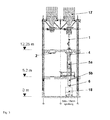
- an emptied but previously granulate-conducting silo (17) is connected to a rigid solid conveying pipe (1) and its pipe outlet flange ends in a telescopic conveying pipe (5a, 5b). Its tube outlet flange (6) extends into a collecting filter carriage (18) for rinsing solutions.
- About the silo (17) can now begin the rinsing process preferably with pure water, which is collected in the bottom filter carriage (18) as a rinse solution. In this way, over a distance of three building stages away a stable but quickly and flexibly mountable pipe joint can be installed, which meets the tightness requirements and the rinse water safely and without leakage in a filter car on the lowest building stage derived.
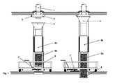
- the telescopic conveyor tube (5a, 5b) itself is positioned manually by means of a ceiling centering (2).
- the driven hopper (4) which is controlled from the lower stage, moves close to the ceiling centering (2), so that the necessary tightness is created for the flushing process.
- An initiator (3) on the ceiling centering (2) detects a correct coupling of the flushing funnel, whereby only then is a flushing release issued.
- the flushing hose (5b) moves with the outlet flange (6) through the bottom opening into the collecting filter carriage (18).
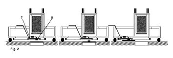
- the bottom cover is previously moved by means of an integrated carriage (7, Fig. 2 ) and a lifting magnet (8) lifted from the bottom opening and offset.
- the mobile telescopic conveyor tube (5a, 5b) is braked and therefore not movable. The brake can only be released again when the initiator on the lifting magnet (8) does not detect a bottom cover.
- the flushing hose (5b) is preferably foldable and extendable. This is known, for example, under compact hose or loading hose.
- the flanges or mating flanges of the telescopic conveying tube according to the invention may optionally additionally contain sensors in a preferred embodiment, as exemplified in US Pat Fig. 1 shown initiator (3), which indicate the position of the flange of a docking device by a so-called initiator query and thus automatically detect a correct docking safely.
- initiators are commercially available devices and are described, for example, under the name NCB15-30GM40-N0-V1. from the company Pepperl and Fuchs. distributed.
- the telescopic conveying tube according to the invention is generally not easily manageable, in particular not during the docking maneuvers, which require high precision.
- the telescopic conveying tube is brought in a preferred embodiment by means of a mobile frame in the desired working position, as exemplified in Fig. 1 , shown schematically.
- the telescopic tube can be with the help of the mobile frame described above ( Fig. 1 ) easily dock and lower the flushing hose through a bottom opening, so that equipment and facilities over a distance of more than one stage height can be securely connected to each other.
- the working platform according to the invention is suitable for moving the telescopic conveying tube from one place to another. Since this work platform can be moved, can be mounted in this way, the telescopic conveyor tube very flexible to different filling position.
- the lifting and lowering devices (in particular the mobile telescopic part) can be supported in a preferred embodiment mechanically, electrically, for example by pneumatic actuators.
- the entire frame can preferably be moved by electric, possibly movable drives.
- Transportable, ie independently movable drives that can be decoupled from the transported goods have the advantage that they can be used for different transport tasks.
- This so-called small tractor or movers can be positively connected to a hoist including an adapter boom to the frame of the work platform.
- the operator can accelerate, decelerate and steer the work platform via a powered rotatable ground wheel of the mover. But it can also be fixed to me the work platform connected drives are used.
- a separate lifting traversing device (7) for example, with electric load magnet (8) is used.
- the initiators are commercially available devices.
- a lid lifting device (7 and 8) is preferably fixedly connected to the mobile frame for the telescopic conveyor tube, with the aid of which existing lid can be raised in floor openings of building stages and optionally put aside so that the flushing hose through the vacant bottom opening can be passed through.
- the lid lifting device (7 and 8) is integrated in the mobile frame so that the lifting mechanism becomes effective directly under the hose outlet flange.
- the construction and operation of such a lid lifting device is characterized by the Fig. 2 , illustrated.
- This lid lifting device (7 and 8) can in principle also be used as a separate, possibly mobile device.
Landscapes
- Engineering & Computer Science (AREA)
- Mechanical Engineering (AREA)
- Quality & Reliability (AREA)
- Filling Or Emptying Of Bunkers, Hoppers, And Tanks (AREA)
- Auxiliary Methods And Devices For Loading And Unloading (AREA)
- Cleaning In General (AREA)
- Loading Or Unloading Of Vehicles (AREA)
Abstract
Description
- Die Erfindung betrifft eine Fördereinrichtung für ein Gemisch aus rieselfähige feinteilige Feststoffe, insbesondere für pulverförmiges und/oder granulatartiges (Misch-)gut, insbesondere Kunststoffgranulat mit einer Flüssigkeit. Insbesondere ist der Gegenstand der Erfindung ein senkrecht angeordnetes und flexibel montierbares Teleskop-Rohr zur Förderung von einem Gemisch aus vorzugsweise Polymer-Granulaten mit einer Flüssigkeit z.B. zum Spülen einer kontaminierten Fördereinrichtung.
- Das bei der Herstellung thermoplastischer Kunststoffen im Reaktor anfallende grießförmige Produkt wird in einem Extruder plastifiziert und zu Einzelsträngen ausgeformt, die mittels eines im Granulierwerkzeug rotierenden Messers zu Granulaten geschnitten werden. Dieses Produkt kann in einem weiteren Schritt durch Compoundierung mit weiteren Komponenten versehen werden.
- Als Compoundieren bezeichnet man in der Polymeraufbereitung die Herstellung der fertigen Kunststoff-Formmasse, dem Compound, aus den Kunststoffrohstoffen unter Zugabe von Füll- und Verstärkungsstoffen, Weichmachern, Haftvermittlern, Gleitmitteln, Stabilisatoren etc.. Die Compoundierung erfolgt überwiegend in Extrudern und umfasst die Verfahrensoperationen Fördern, Aufschmelzen, Dispergieren, Mischen, Entgasen und Druckaufbau.
- Bei der Granulierung wird die Schmelze dann durch die Öffnungen einer Düsenplatte gepresst, so dass anschließend im Falle einer Stranggranulierung zunächst Schmelzestränge erzeugt werden, die dann bei der Granulierung Zylindergranulat ergeben oder aber im Falle einer Kopfgranulierung direkt am Austritt an der Düsenplatte geschnitten werden und dann Linsen- oder Kugelgranulat ergeben. Die Granulierung kann beispielsweise in einem Flüssigkeitsstrom erfolgen, der die Granulate kühlt und ein Agglomerieren weitgehend vermeidet. Anschließend wird das Granulat getrocknet und gesiebt.
- Im Anschluss zur Granulierung nach der Herstellung oder nach der Compoundierung wird in der Regel das Produkt pneumatisch zu einem Silo oder Bunker gefördert. Anschließend wird den Silos oder Bunker das Schüttgut entnommen und in Container oder Silofahrzeuge gefüllt, oder es erfolgt eine Absackung des Schüttgutes in Big Bags, Oktabins oder Säcke. Bei jedem dieser Schritte können Stäube/Beläge z.B. durch Abrieb entstehen, die zusätzlich zum Schüttgut selbst dann bei einem Schüttgutwechsel eine Kontamination verursachen können.
- Typische Schüttgüter sind z.B., Baustoffe, wie Oberboden, Sand, Kies, Schotter, Zement, andere mineralische Güter, wie Erz, Streusalz, und Lebensmittel, wie Getreide, Zucker, Speisesalz, Kaffee, Mehl, sowie pulverförmige Güter wie Pigmente, Füllstoffe, Granulate, Pellets usw.
- Gleichzeitig wird die Forderung nach Flexibilität immer höher, so dass in einer Abfüllanlage Geräte je nach Bedarf austauschbar sind. Beispielsweise kann bei einem Schüttgut der Bedarf nach einem Sichter (Entstaubungseinheit) bestehen, um feine Partikel zu entfernen, wobei für andere Schüttgüter nur ein Förderrohr notwendig ist. Zudem sind die Investitionskosten nicht unerheblich, so dass eine flexible Lösung zum Einsatz beispielsweise eines Förderrohres an verschiedenen Orten einer Anlage ermöglicht wird.
-
DE 195 272 40 C1 beschreibt eine Fördereinrichtung, wobei ein Abschnitt der Förderleitung zwischen zwei starr zueinander beabstandeten Widerlagern auswechselbar angeordnet ist und der auswechselbare Förderleitungsabschnitt unter Wirkung einer Spannfeder teleskopierbar ausgebildet ist und sich die Enden der Teleskopanordnung an den Widerlagern abstützen. Nachteilig ist der konstruktionsbedingte entsprechende Aufwand für die Reinigung zur Vermeidung von Kontamination sobald ein anderer Feststoff befördert wird, insbesondere im Rohr-Flanschbereich und im Rohr-Innenverlauf. - Die Forderung nach leichter Auswaschbarkeit von Puffer- und Fördereinrichtungen vor dem Befüllen bzw. Befördern eines anderen Schüttguttyps wird jedoch zunehmend häufiger gestellt.
- Da der bisherige Stand der Technik keine hinreichende Lösung zu diesem Problem ermöglicht, war es Aufgabe der vorliegenden Erfindung, eine Fördereinrichtung bereitzustellen, das eine Verbindung zwischen verschiedenen Ebenen, die auf unterschiedlicher Höhe senkrecht übereinander angeordnet sind, ermöglicht, Dabei gilt es, ein Feststoff-Flüssigkeitsgemisch aus Reinigungsprozessen aus unterschiedlichen Bereichen einer Ebene in die darunterliegenden Ebenen weiterzuleiten. Diese Teleskop-Förderrohre sollten insbesondere an unterschiedlichen Positionen innerhalb eines zu spülendes Abfüllgebäudes einsetzbar sein, und zu diesem Zweck austauschbar und leicht aber dennoch sicher montierbar sein.
- Die Aufgabe der vorliegenden Erfindung ist es daher, die Nachteile des Standes der Technik zu beheben.
- Die gestellte Aufgabe wurde durch Bereitstellen einer Fördervorrichtung gelöst, die ein teleskopierbares Förderrohr beinhaltet und die folgenden Merkmale aufweist:
- a) Anordnung des Teleskoprohres (5a) auf einem mobilen Rahmen zum Transport des Rohres an unterschiedliche Reinigungsstellen auf der Bühne, wobei der mobile Rahmen Hub-/Senkeinrichtung zur Positionierung des Rohres an unterschiedlichen Andockvorrichtungen auf einer Bühne enthält
- b) Trichter (4) am Teleskoprohreingang mit Andockkragen zum Aufsetzen auf die Deckenzentrierung (2)
- c) Deckenzentrierung (2) mit Initiator (3) zur automatisierten Erkennung einer Trichterandockung
- d) Spülschlauch (5b) mit Hub-Senkvorrichtung
- e) eine Hebe-Verfahrvornchtung (7, 8) zur sicheren Entnahme des Bodendeckels
- Das Teleskop-Förderrohr ist kein starres Rohr, sondern besteht aus zwei oder mehreren Rohrsegmenten - die nicht zwangsläufig eine zylindrische Form aufweisen müssen, sondern auch einen vieleckigen Querschnitt aufweisen können - die zusammengesetzt sind und sich in einander verschieben lassen (siehe
Fig. 1 ). Auf diese Weise entsteht ein Förderrohr, dessen Länge sich durch teleskopartiges Ineinanderschieben oder Auseinanderziehen der miteinander in Verbindung stehenden Rohrsegmente variieren lässt. - Ein möglicher Arbeitsvorgang, der durch das erfindungsgemäße Teleskop-Förderrohr (
Fig. 1 ) wirkungsvoll unterstützt wird, wird nachfolgend am Beispiel der Silo-Spülung erläutert (siehe auchFig. 3 ). - Hier wird beispielsweise ein entleertes aber zuvor Granulat-führendes Silo (17) mit einem starren Feststoff-Förderrohr (1) verbunden und dessen Rohr-Auslaufflansch in ein Teleskop-Förderrohr (5a, 5b) endet. Dessen Rohr-Auslaufflansch (6) reicht bis in einem Auffangfilterwagen (18) für Spüllösungen. Über das Silo (17) kann nun der Spülprozess vorzugsweise mit reinem Wasser beginnen, das im untersten Filterwagen (18) als Spüllösung aufgefangen wird. Auf diese Weise lässt sich über eine Distanz von drei Gebäude-Bühnen hinweg eine stabile aber dennoch schnell und flexibel montierbare Rohrverbindung installieren, die den Dichtheits-Anforderungen genügt und das Spülwasser sicher und ohne Leckagen in einen Filterwagen auf der untersten Gebäudebühne ableitet.
- Das Teleskop-Förderrohr (5a, 5b) selbst wird manuell mit Hilfe einer Deckenzentrierung (2) positioniert. Dabei verfährt der angetriebene und von der unteren Bühne aus gesteuerte Trichter (4) dicht auf die Deckenzentrierung (2) auf, so dass für den Spülprozess die notwendige Dichtheit entsteht. Ein Initiator (3) an der Deckenzentrierung (2) erkennt eine korrekte Ankopplung des Spültrichters, wodurch erst dann eine Spülfreigabe erteilt wird. Ebenso verfährt der Spülschlauch (5b) mit dem Auslaufflansch (6) durch die Bodenöffnung bis in den Auffangfilterwagen (18). Der Bodendeckel wird zuvor mittels eines integrierten Verfahrwagens (7,
Fig. 2 ) und einem Hub-Magneten (8) aus der Bodenöffnung gehoben und versetzt. Zur Sicherung vor Personenabstürzen ist das mobile Teleskop-Förderrohr (5a, 5b) gebremst und somit nicht verfahrbar. Die Bremse lässt sich erst wieder lösen, wenn der Initiator am Hub-Magnet (8) keinen Bodendeckel erkennt. - Diese Anordnung hat gegenüber den sonst üblicherweise verwendeten flexiblen Schläuchen enorme Vorteile hinsichtlich der Anforderungen an Arbeitssicherheit an Sauberkeit und an Flexibilität, wobei Flexibilität insbesondere die schnelle Montage bedeutet.
- Der Spülschlauch (5b) ist bevorzugt faltbar und ausfahrbar. Dieser ist beispielsweise auch unter kompakter Schlauch oder Verladeschlauch bekannt.
- Die Flansche oder Gegenflansche des erfindungsgemäßen Teleskop-Förderrohres können gegebenenfalls in einer bevorzugten Ausführungsform zusätzlich Sensoren enthalten, wie der beispielhaft in
Fig. 1 gezeigte Initiator (3), die die Stellung des Flansches einer Andockvorrichtung durch eine sogenannte Initiator-Abfrage anzeigen und somit einen korrekten Andockvorgang automatisiert sicher erkennen lassen. Solche Initiatoren sind handelsübliche Geräte und werden beispielsweise unter der Bezeichnung NCB15-30GM40-N0-V1. von der Fa. Pepperl und Fuchs. vertrieben. - Im Kontext der vorliegenden Anmeldung werden die Begriffe Sensor und Initiator gleichbedeutend verwendet.
- Das erfindungsgemäße Teleskop-Förderrohr ist aufgrund seiner Abmessungen und seines Eigengewichtes in der Regel nicht ohne weiteres manuell handhabbar, insbesondere nicht während den Andock-Manövern, die eine hohe Präzision erfordern. Um diese Handhabung zu erleichtern, wird das Teleskop-Förderrohr in einer bevorzugten Ausführungsform mit Hilfe eines mobilen Rahmens in die gewünschte Arbeitsposition gebracht, wie beispielhaft in
Fig. 1 . schematisch dargestellt. - Das teleskopartige Förderrohr lässt sich mit Hilfe des oben beschriebenen mobilen Rahmens (
Fig. 1 ) problemlos andocken und den Spülschlauch durch eine Bodenöffnung hindurch absenken, so dass auch Apparate und Einrichtungen über eine Distanz von mehr als einer Bühnenhöhe sicher mit einander verbunden werden können. - Die erfindungsgemäße Arbeitsplattform ist dazu geeignet, das Teleskop-Förderrohr von einem Ort zum Anderen zu bewegen. Da diese Arbeitsplattform verfahren werden kann, lässt sich auf diese Weise das Teleskop-Förderrohr sehr flexibel an unterschiedliche Abfüll-Position montieren. Die Hebe- und Senk-Vorrichtungen (insbesondere der mobile teleskopierbare Teil) können in einer bevorzugten Ausführungsform mechanisch, elektrisch beispielsweise durch pneumatische Antriebe unterstützt werden.
- Optional kann der gesamte Rahmen vorzugsweise durch elektrische, gegebenenfalls ortsbewegliche Antriebe bewegt werden. Ortsbewegliche, d.h. eigenständig verfahrbare vom Transportgut entkoppelbare Antriebe haben den Vorteil, dass Sie für unterschiedliche Transportaufgaben eingesetzt werden können. Dieser sogenannte Kleinschlepper oder Mover läßt sich mit einem Hubwerk inkl. einem Adaptionsausleger an den Rahmen der Arbeitsplattform formschlüssig verbinden. Somit kann der Bediener über ein angetriebenes drehbares Bodenrad des Movers die Arbeitsplattform beschleunigen, abbremsen und lenken. Es können aber auch fest mir der Arbeitsplattform verbundene Antriebe verwendet werden.
- Zur weiteren Arbeitssicherheit wird in einer weiteren bevorzugten Ausführungsform für das Öffnen des Bodendeckels (wenn vorhanden) zur Absicherung der Bodenöffnung eine separate Hebe-Verfahrvorrichtung (7) beispielsweise mit elektrischem Lastmagnet (8) eingesetzt. Die Initiatoren sind handelsübliche Geräte.
- So ist bevorzugt eine Deckelhebe-Vorrichtung (7 und 8) mit dem mobilen Rahmen für das Teleskop-Förderrohr fest verbunden, mit deren Hilfe vorhandene Deckel in Bodenöffnungen von Gebäudebühnen angehoben und gegebenenfalls bei Seite gelegt werden können, damit der Spülschlauch durch die frei gewordene Bodenöffnung hindurch geführt werden kann. Die Deckelhebe-Vorrichtung (7 und 8) ist dabei so in dem mobilen Rahmen integriert, dass der Hebemechanismus direkt unter dem Schlauch-Auslaufflansch wirksam wird. Die Konstruktion und Funktionsweise einer solchen Deckelhebe-Vorrichtung wird durch die
Fig. 2 . veranschaulicht. - Diese Deckelhebe-Vorrichtung (7 und 8) kann grundsätzlich auch als separate, gegebenenfalls mobile Vorrichtung verwendet werden.
- Die Merkmale des erfindungsgemäßen Teleskop-Förderrohres werden in den
Figuren 1. bis 3 . veranschaulicht, ohne sie dadurch auf den Inhalt dieser Figuren einzuschränken. -
Fig. 1 . zeigt ein Teleskop-Förderrohr im eingefahrenden - und im angedockten Zustand -
Fig. 2 . zeigt eine Bodendeckel Hebe- und Verfahrvorrichtung mit den einzelnen Arbeitsschritten -
Fig. 3 . zeigt den Einsatz eines Teleskop-Förderrohrs am Beispiel einer Silo-Spülung
Claims (13)
- Fördervorrichtung, die ein teleskopierbares Förderrohr und wenigstens folgende Merkmale beinhalteta) Anordnung des Teleskoprohres (5a) auf einem mobilen Rahmen zum Transport des Rohres an unterschiedliche Reinigungsstellen auf der Bühne, wobei der mobile Rahmen Hub-/Senkeinrichtung zur Positionierung des Rohres an unterschiedlichen Andockvorrichtungen auf einer Bühne enthältb) Trichter (4) am Teleskoprohreingang mit Andockkragen zum Aufsetzen auf Deckenzentrierung (2)c) Deckenzentrierung (2) mit Initiator (3) zur automatisierten Erkennung einer Trichterandockungd) Spülschlauch (5b) mit Hub-Senkvorrichtunge) eine Hebe-Verfahrvorrichtung (7, 8) zur sicheren Entnahme des Bodendeckels
- Fördervorrichtung gemäß Anspruch 1, dadurch gekennzeichnet, dass Sensoren an einem oder beiden Flanschen oder Gegenflanschen des Förderrohres angebracht sind.
- Fördervorrichtung gemäß Anspruch 2, dadurch gekennzeichnet, dass der Sensor ein korrektes Andocken des Flansches erkennt und die Spülfreigabe übermittelt.
- Fördervorrichtung gemäß einem der Ansprüche 1 bis 3, dadurch gekennzeichnet, dass das Rohr auf einem mobilen Rahmen zum Transport des Rohres an unterschiedliche Abfüllstellen auf der Bühne angeordnet ist, wobei der mobile Rahmen Hebe- und Senk-Einrichtungen zur Positionierung des Rohres an unterschiedlichen Andockvorrichtungen auf einer Bühne enthält.
- Fördervorrichtung gemäß Anspruch 4 dadurch gekennzeichnet, dass Hebe-, Senk-Einrichtungen durch pneumatische Antriebe unterstützt werden.
- Fördereinrichtung gemäß Anspruch 4 oder 5, dadurch gekennzeichnet, dass eine Hebe-Verfahrvorrichtung (8) zur sicheren Entnahme des Bodendeckels an dem mobilen Rahmen vorhanden ist.
- Fördervorrichtung gemäß Anspruch 6, dadurch gekennzeichnet, dass bei einer Deckelentnahme der mobile Rahmen gebremst ist.
- Fördervorrichtung gemäß Anspruch 6 oder 7, dadurch gekennzeichnet, dass die Bremse erst gelöst wird, wenn der Initiator am Hub-Magneten keinen Bodendeckel erkennt.
- Fördervorrichtung gemäß einem der Ansprüche 1 bis 8., dadurch gekennzeichnet, dass Arbeitsplattform durch elektrische, gegebenenfalls ortsbewegliche Antriebe bewegt werden.
- Fördervorrichtung gemäß einem der Ansprüche 1 bis 9, dadurch gekennzeichnet, dass durch die Deckenzentrierung (2) die Positionierung des Teleskop-Rohres erfolgt
- Fördervorrichtung gemäß dem Anspruchs 10, dadurch gekennzeichnet, dass durch das Aufliegen des Trichters (4) auf die Deckenzentrierung (2) eine Abdichtung erfolgt.
- Verwendung einer Fördereinrichtung gemäß einem der Ansprüche 1 bis 11 zur Förderung von Schüttgut oder Gemische von Schüttgut und Flüssigkeiten.
- Verwendung einer Fördereinrichtung gemäß Anspruch 12 zur Förderung von Polycarbonat-Granulat oder Gemische von Polycarbonat-Granulat und Flüssigkeiten.
Priority Applications (1)
| Application Number | Priority Date | Filing Date | Title |
|---|---|---|---|
| EP20120160905 EP2505521B1 (de) | 2011-03-30 | 2012-03-23 | Fördereinrichtung für pulverförmiges und/oder granuliertes Gut sowie Gemische dieses Gutes mit Flüssigkeiten |
Applications Claiming Priority (2)
| Application Number | Priority Date | Filing Date | Title |
|---|---|---|---|
| EP11160515 | 2011-03-30 | ||
| EP20120160905 EP2505521B1 (de) | 2011-03-30 | 2012-03-23 | Fördereinrichtung für pulverförmiges und/oder granuliertes Gut sowie Gemische dieses Gutes mit Flüssigkeiten |
Publications (2)
| Publication Number | Publication Date |
|---|---|
| EP2505521A1 true EP2505521A1 (de) | 2012-10-03 |
| EP2505521B1 EP2505521B1 (de) | 2015-01-07 |
Family
ID=44519904
Family Applications (1)
| Application Number | Title | Priority Date | Filing Date |
|---|---|---|---|
| EP20120160905 Not-in-force EP2505521B1 (de) | 2011-03-30 | 2012-03-23 | Fördereinrichtung für pulverförmiges und/oder granuliertes Gut sowie Gemische dieses Gutes mit Flüssigkeiten |
Country Status (5)
| Country | Link |
|---|---|
| US (1) | US9051135B2 (de) |
| EP (1) | EP2505521B1 (de) |
| CN (1) | CN102729360B (de) |
| ES (1) | ES2534127T3 (de) |
| RU (1) | RU2012111694A (de) |
Cited By (1)
| Publication number | Priority date | Publication date | Assignee | Title |
|---|---|---|---|---|
| DE102013003113A1 (de) * | 2013-02-25 | 2014-08-28 | Pelletron Corp. | Autonom arbeitender mobiler Sichter |
Families Citing this family (9)
| Publication number | Priority date | Publication date | Assignee | Title |
|---|---|---|---|---|
| ES2533849T3 (es) * | 2011-03-30 | 2015-04-15 | Bayer Intellectual Property Gmbh | Dispositivo de transporte para producto pulverulento y/o granulado |
| CN104444453B (zh) * | 2014-12-04 | 2016-08-24 | 广东宏工物料自动化系统有限公司 | 移动混料仓定位装置 |
| CN105564924B (zh) * | 2016-03-04 | 2018-03-23 | 神华集团有限责任公司 | 高温固体物料的密闭输送方法 |
| RU2634007C1 (ru) * | 2016-12-28 | 2017-10-23 | Игорь Феликсович Шлегель | Устройство для объемного дозирования сыпучих материалов |
| RU2689080C1 (ru) * | 2018-03-21 | 2019-05-23 | Общество с ограниченной ответственностью "РэилМатик" | Автоматический погрузо-разгрузочный мобильный комплекс |
| CN109091967A (zh) * | 2018-09-30 | 2018-12-28 | 亚都科技集团有限公司 | 一种滤芯结构及空气净化器 |
| WO2020210830A1 (en) * | 2019-04-11 | 2020-10-15 | Henery Drew P | Conduit access |
| CN111776638A (zh) * | 2020-07-20 | 2020-10-16 | 芜湖华洁环保设备有限公司 | 一种输送机角度可调节的螺旋式输送机 |
| CN114313906B (zh) * | 2021-12-01 | 2024-07-05 | 中国石油化工集团有限公司 | 自动连续的无尘供砂装置 |
Citations (6)
| Publication number | Priority date | Publication date | Assignee | Title |
|---|---|---|---|---|
| US4125195A (en) * | 1977-03-23 | 1978-11-14 | Edc Inc. | Dry rock loading spout system |
| DE19527240C1 (de) | 1995-07-26 | 1996-09-26 | Ambos & Langbein Elektro Elekt | Fördereinrichtung für pulverförmiges und/oder granuliertes Gut, insbesondere für eine kunststoffverarbeitende Maschine |
| US5881780A (en) * | 1997-08-05 | 1999-03-16 | Dcl, Inc. | Apapratus for and method of locating the center of an opening in a vehicle |
| EP1475348A1 (de) * | 2003-05-08 | 2004-11-10 | Firma Haver & Boecker | Ferngesteuerte Vorrichtung und Verfahren zum Beladen von Fahrzeugen mit Schüttgütern |
| DE202005016035U1 (de) * | 2005-10-10 | 2006-01-26 | Alfred Bolz Gerätebau GmbH | Transfervorrichtung für die Bereitstellung von Prozessstoffen und die Befüllung von Prozessgeräten |
| EP2070850A1 (de) * | 2007-12-10 | 2009-06-17 | René Brunone | Beladeanlage von Produkten, die auf verschiedene Kübeln verteilt sind |
Family Cites Families (11)
| Publication number | Priority date | Publication date | Assignee | Title |
|---|---|---|---|---|
| US3430639A (en) * | 1966-11-08 | 1969-03-04 | Pomona Valley Creamery | Cleaning means for liquid dispensers |
| US3944090A (en) * | 1974-10-04 | 1976-03-16 | Robert J. Flood | Method for loading grain cars |
| BR8100132A (pt) * | 1980-01-11 | 1981-07-28 | Delbag Luftfilter Gmbh | Elementos de filtracao |
| DE4319095C2 (de) * | 1993-06-08 | 1995-04-20 | Siemens Ag | Vorrichtung zur Dekontamination einer radioaktiv kontaminierten Oberfläche |
| ITBO20030454A1 (it) * | 2003-07-30 | 2005-01-31 | Vima Impianti S R L | Apparato per il trasferimento di materiale incoerente. |
| DE102007044181B4 (de) * | 2007-09-15 | 2009-05-28 | Uhde Gmbh | Füllteleskop zum Befüllen von Koksöfen |
| CN201587056U (zh) * | 2009-11-30 | 2010-09-22 | 安阳塑化股份有限公司 | 分布控制pe粒料气力配送系统用分离过滤装置 |
| EP2505273A1 (de) * | 2011-03-30 | 2012-10-03 | Bayer MaterialScience AG | Mobile Zellenradschleuse |
| ES2533847T3 (es) * | 2011-03-30 | 2015-04-15 | Bayer Intellectual Property Gmbh | Dispositivo de transporte para producto pulverulento y/o granulado |
| IN2012DE00853A (de) * | 2011-03-30 | 2015-08-28 | Bayer Materialscience Ag | |
| ES2533849T3 (es) * | 2011-03-30 | 2015-04-15 | Bayer Intellectual Property Gmbh | Dispositivo de transporte para producto pulverulento y/o granulado |
-
2012
- 2012-03-23 ES ES12160905.1T patent/ES2534127T3/es active Active
- 2012-03-23 EP EP20120160905 patent/EP2505521B1/de not_active Not-in-force
- 2012-03-26 US US13/429,914 patent/US9051135B2/en not_active Expired - Fee Related
- 2012-03-27 RU RU2012111694/05A patent/RU2012111694A/ru not_active Application Discontinuation
- 2012-03-28 CN CN201210085649.9A patent/CN102729360B/zh not_active Expired - Fee Related
Patent Citations (6)
| Publication number | Priority date | Publication date | Assignee | Title |
|---|---|---|---|---|
| US4125195A (en) * | 1977-03-23 | 1978-11-14 | Edc Inc. | Dry rock loading spout system |
| DE19527240C1 (de) | 1995-07-26 | 1996-09-26 | Ambos & Langbein Elektro Elekt | Fördereinrichtung für pulverförmiges und/oder granuliertes Gut, insbesondere für eine kunststoffverarbeitende Maschine |
| US5881780A (en) * | 1997-08-05 | 1999-03-16 | Dcl, Inc. | Apapratus for and method of locating the center of an opening in a vehicle |
| EP1475348A1 (de) * | 2003-05-08 | 2004-11-10 | Firma Haver & Boecker | Ferngesteuerte Vorrichtung und Verfahren zum Beladen von Fahrzeugen mit Schüttgütern |
| DE202005016035U1 (de) * | 2005-10-10 | 2006-01-26 | Alfred Bolz Gerätebau GmbH | Transfervorrichtung für die Bereitstellung von Prozessstoffen und die Befüllung von Prozessgeräten |
| EP2070850A1 (de) * | 2007-12-10 | 2009-06-17 | René Brunone | Beladeanlage von Produkten, die auf verschiedene Kübeln verteilt sind |
Cited By (2)
| Publication number | Priority date | Publication date | Assignee | Title |
|---|---|---|---|---|
| DE102013003113A1 (de) * | 2013-02-25 | 2014-08-28 | Pelletron Corp. | Autonom arbeitender mobiler Sichter |
| DE102013003113B4 (de) * | 2013-02-25 | 2016-05-12 | Pelletron Corp. | Autonom arbeitender mobiler Sichter |
Also Published As
| Publication number | Publication date |
|---|---|
| CN102729360A (zh) | 2012-10-17 |
| CN102729360B (zh) | 2016-09-28 |
| ES2534127T3 (es) | 2015-04-17 |
| EP2505521B1 (de) | 2015-01-07 |
| US20120251249A1 (en) | 2012-10-04 |
| US9051135B2 (en) | 2015-06-09 |
| RU2012111694A (ru) | 2013-10-10 |
Similar Documents
| Publication | Publication Date | Title |
|---|---|---|
| EP2505521B1 (de) | Fördereinrichtung für pulverförmiges und/oder granuliertes Gut sowie Gemische dieses Gutes mit Flüssigkeiten | |
| EP2505519B1 (de) | Fördereinrichtung für pulverförmiges und/oder granuliertes Gut | |
| EP2505520B1 (de) | Fördervorrichtung für pulverförmiges und/oder granuliertes Gut | |
| EP2505272B1 (de) | Mobiler Sichter | |
| EP1619124B1 (de) | Vorrichtung zum Abfüllen pulverartigen Haufwerks sowie damit durchführbares Verfahren | |
| DE69121529T2 (de) | Anhänger für Containertransport | |
| DE2235747A1 (de) | Verfahren und vorrichtung zum verladen von schuettgut | |
| EP2564946A1 (de) | Verfahren zum Reinigen von Dosiervorrichtungen, die zum Beschicken von Vorrichtungen - zum Beispiel Extruder, Spritzgussmaschinen oder dergleichen - mit Schüttgütern - Pelletts, Spänen, Granulaten, Pulvern, Flakes, Körnen, Mehl oder dergleichen - dienen, und Vorrichtung zur Durchführung eines derartigen Verfahrens und Steuerung für die Reinigung einer derartigen Dosiervorrichtung | |
| EP0288799B1 (de) | In einem Stapelgerüst angeordneter Container | |
| EP2505273A1 (de) | Mobile Zellenradschleuse | |
| DE102013008310A1 (de) | Autonom arbeitender mobiler Sichter mit nachgeschalteter Abfüllanlage von Gebinden | |
| DE7730505U1 (de) | Mobile entladevorrichtung fuer massengut | |
| DE2528483C3 (de) | Vorrichtung zum Entladen von mit schlecht fließendem, brückenbildendem Schüttgut beladenen Schiffen | |
| DE3390175T1 (de) | Apparat und Verfahren zum Entladen von Schüttgütern | |
| DE102010031769B4 (de) | Dosiervorrichtung für den Schüttgut-Inhalt von Großtaschen | |
| AT515165A1 (de) | Ladeeinrichtung einer Fertigbetonmischanlage | |
| DE60105121T2 (de) | Vorrichtung zum Entleeren eines Fasses | |
| EP2059375B1 (de) | Verfahren und vorrichtung zum betontransport auf schienen | |
| EP0117922B1 (de) | Vorrichtung zum Fördern von staubförmigen bis grobkörnigen Gütern, insbesondere Dammbaustoffen im Untertagebergbau | |
| EP1997753B1 (de) | Verfahren und Anordnung zum Entladen von rieselfähigen Medien aus Tanklastzügen | |
| DE10144121A1 (de) | Baustoffbunker für Untertage | |
| DE19639856C2 (de) | Verfahren und Vorrichtung zum Fördern von Feinstoffen als Zuschlag in körnigen Produkten | |
| EP0427931A1 (de) | Vorrichtung zum Entleeren von Schüttgut enthaltenden Silos | |
| DE102005008663A1 (de) | Schüttguttransportvorrichtung | |
| DE202020101553U1 (de) | Wechsel-Adapter, Handhabungs-Einheit mit Wechseladapter |
Legal Events
| Date | Code | Title | Description |
|---|---|---|---|
| PUAI | Public reference made under article 153(3) epc to a published international application that has entered the european phase |
Free format text: ORIGINAL CODE: 0009012 |
|
| AK | Designated contracting states |
Kind code of ref document: A1 Designated state(s): AL AT BE BG CH CY CZ DE DK EE ES FI FR GB GR HR HU IE IS IT LI LT LU LV MC MK MT NL NO PL PT RO RS SE SI SK SM TR |
|
| AX | Request for extension of the european patent |
Extension state: BA ME |
|
| 17P | Request for examination filed |
Effective date: 20130403 |
|
| RAP1 | Party data changed (applicant data changed or rights of an application transferred) |
Owner name: BAYER INTELLECTUAL PROPERTY GMBH |
|
| GRAP | Despatch of communication of intention to grant a patent |
Free format text: ORIGINAL CODE: EPIDOSNIGR1 |
|
| INTG | Intention to grant announced |
Effective date: 20140808 |
|
| GRAS | Grant fee paid |
Free format text: ORIGINAL CODE: EPIDOSNIGR3 |
|
| GRAA | (expected) grant |
Free format text: ORIGINAL CODE: 0009210 |
|
| AK | Designated contracting states |
Kind code of ref document: B1 Designated state(s): AL AT BE BG CH CY CZ DE DK EE ES FI FR GB GR HR HU IE IS IT LI LT LU LV MC MK MT NL NO PL PT RO RS SE SI SK SM TR |
|
| REG | Reference to a national code |
Ref country code: GB Ref legal event code: FG4D Free format text: NOT ENGLISH |
|
| REG | Reference to a national code |
Ref country code: CH Ref legal event code: EP |
|
| REG | Reference to a national code |
Ref country code: IE Ref legal event code: FG4D Free format text: LANGUAGE OF EP DOCUMENT: GERMAN |
|
| REG | Reference to a national code |
Ref country code: AT Ref legal event code: REF Ref document number: 705532 Country of ref document: AT Kind code of ref document: T Effective date: 20150215 |
|
| REG | Reference to a national code |
Ref country code: DE Ref legal event code: R096 Ref document number: 502012002011 Country of ref document: DE Effective date: 20150219 |
|
| REG | Reference to a national code |
Ref country code: NL Ref legal event code: T3 |
|
| REG | Reference to a national code |
Ref country code: ES Ref legal event code: FG2A Ref document number: 2534127 Country of ref document: ES Kind code of ref document: T3 Effective date: 20150417 |
|
| REG | Reference to a national code |
Ref country code: LT Ref legal event code: MG4D |
|
| PG25 | Lapsed in a contracting state [announced via postgrant information from national office to epo] |
Ref country code: NO Free format text: LAPSE BECAUSE OF FAILURE TO SUBMIT A TRANSLATION OF THE DESCRIPTION OR TO PAY THE FEE WITHIN THE PRESCRIBED TIME-LIMIT Effective date: 20150407 Ref country code: HR Free format text: LAPSE BECAUSE OF FAILURE TO SUBMIT A TRANSLATION OF THE DESCRIPTION OR TO PAY THE FEE WITHIN THE PRESCRIBED TIME-LIMIT Effective date: 20150107 Ref country code: LT Free format text: LAPSE BECAUSE OF FAILURE TO SUBMIT A TRANSLATION OF THE DESCRIPTION OR TO PAY THE FEE WITHIN THE PRESCRIBED TIME-LIMIT Effective date: 20150107 Ref country code: BG Free format text: LAPSE BECAUSE OF FAILURE TO SUBMIT A TRANSLATION OF THE DESCRIPTION OR TO PAY THE FEE WITHIN THE PRESCRIBED TIME-LIMIT Effective date: 20150407 Ref country code: FI Free format text: LAPSE BECAUSE OF FAILURE TO SUBMIT A TRANSLATION OF THE DESCRIPTION OR TO PAY THE FEE WITHIN THE PRESCRIBED TIME-LIMIT Effective date: 20150107 Ref country code: SE Free format text: LAPSE BECAUSE OF FAILURE TO SUBMIT A TRANSLATION OF THE DESCRIPTION OR TO PAY THE FEE WITHIN THE PRESCRIBED TIME-LIMIT Effective date: 20150107 |
|
| PG25 | Lapsed in a contracting state [announced via postgrant information from national office to epo] |
Ref country code: PL Free format text: LAPSE BECAUSE OF FAILURE TO SUBMIT A TRANSLATION OF THE DESCRIPTION OR TO PAY THE FEE WITHIN THE PRESCRIBED TIME-LIMIT Effective date: 20150107 Ref country code: LV Free format text: LAPSE BECAUSE OF FAILURE TO SUBMIT A TRANSLATION OF THE DESCRIPTION OR TO PAY THE FEE WITHIN THE PRESCRIBED TIME-LIMIT Effective date: 20150107 Ref country code: IS Free format text: LAPSE BECAUSE OF FAILURE TO SUBMIT A TRANSLATION OF THE DESCRIPTION OR TO PAY THE FEE WITHIN THE PRESCRIBED TIME-LIMIT Effective date: 20150507 Ref country code: RS Free format text: LAPSE BECAUSE OF FAILURE TO SUBMIT A TRANSLATION OF THE DESCRIPTION OR TO PAY THE FEE WITHIN THE PRESCRIBED TIME-LIMIT Effective date: 20150107 Ref country code: GR Free format text: LAPSE BECAUSE OF FAILURE TO SUBMIT A TRANSLATION OF THE DESCRIPTION OR TO PAY THE FEE WITHIN THE PRESCRIBED TIME-LIMIT Effective date: 20150408 |
|
| REG | Reference to a national code |
Ref country code: DE Ref legal event code: R097 Ref document number: 502012002011 Country of ref document: DE |
|
| PG25 | Lapsed in a contracting state [announced via postgrant information from national office to epo] |
Ref country code: MC Free format text: LAPSE BECAUSE OF FAILURE TO SUBMIT A TRANSLATION OF THE DESCRIPTION OR TO PAY THE FEE WITHIN THE PRESCRIBED TIME-LIMIT Effective date: 20150107 Ref country code: CZ Free format text: LAPSE BECAUSE OF FAILURE TO SUBMIT A TRANSLATION OF THE DESCRIPTION OR TO PAY THE FEE WITHIN THE PRESCRIBED TIME-LIMIT Effective date: 20150107 Ref country code: SK Free format text: LAPSE BECAUSE OF FAILURE TO SUBMIT A TRANSLATION OF THE DESCRIPTION OR TO PAY THE FEE WITHIN THE PRESCRIBED TIME-LIMIT Effective date: 20150107 Ref country code: DK Free format text: LAPSE BECAUSE OF FAILURE TO SUBMIT A TRANSLATION OF THE DESCRIPTION OR TO PAY THE FEE WITHIN THE PRESCRIBED TIME-LIMIT Effective date: 20150107 Ref country code: EE Free format text: LAPSE BECAUSE OF FAILURE TO SUBMIT A TRANSLATION OF THE DESCRIPTION OR TO PAY THE FEE WITHIN THE PRESCRIBED TIME-LIMIT Effective date: 20150107 Ref country code: RO Free format text: LAPSE BECAUSE OF FAILURE TO SUBMIT A TRANSLATION OF THE DESCRIPTION OR TO PAY THE FEE WITHIN THE PRESCRIBED TIME-LIMIT Effective date: 20150107 Ref country code: LU Free format text: LAPSE BECAUSE OF FAILURE TO SUBMIT A TRANSLATION OF THE DESCRIPTION OR TO PAY THE FEE WITHIN THE PRESCRIBED TIME-LIMIT Effective date: 20150323 |
|
| REG | Reference to a national code |
Ref country code: CH Ref legal event code: PL |
|
| PLBE | No opposition filed within time limit |
Free format text: ORIGINAL CODE: 0009261 |
|
| STAA | Information on the status of an ep patent application or granted ep patent |
Free format text: STATUS: NO OPPOSITION FILED WITHIN TIME LIMIT |
|
| 26N | No opposition filed |
Effective date: 20151008 |
|
| REG | Reference to a national code |
Ref country code: IE Ref legal event code: MM4A |
|
| PG25 | Lapsed in a contracting state [announced via postgrant information from national office to epo] |
Ref country code: CH Free format text: LAPSE BECAUSE OF NON-PAYMENT OF DUE FEES Effective date: 20150331 Ref country code: LI Free format text: LAPSE BECAUSE OF NON-PAYMENT OF DUE FEES Effective date: 20150331 Ref country code: IE Free format text: LAPSE BECAUSE OF NON-PAYMENT OF DUE FEES Effective date: 20150323 |
|
| REG | Reference to a national code |
Ref country code: DE Ref legal event code: R081 Ref document number: 502012002011 Country of ref document: DE Owner name: COVESTRO DEUTSCHLAND AG, DE Free format text: FORMER OWNER: BAYER INTELLECTUAL PROPERTY GMBH, 40789 MONHEIM, DE |
|
| REG | Reference to a national code |
Ref country code: FR Ref legal event code: PLFP Year of fee payment: 5 |
|
| PG25 | Lapsed in a contracting state [announced via postgrant information from national office to epo] |
Ref country code: SI Free format text: LAPSE BECAUSE OF FAILURE TO SUBMIT A TRANSLATION OF THE DESCRIPTION OR TO PAY THE FEE WITHIN THE PRESCRIBED TIME-LIMIT Effective date: 20150107 |
|
| REG | Reference to a national code |
Ref country code: NL Ref legal event code: PD Owner name: COVESTRO DEUTSCHLAND AG; DE Free format text: DETAILS ASSIGNMENT: VERANDERING VAN EIGENAAR(S), OVERDRACHT; FORMER OWNER NAME: BAYER INTELLECTUAL PROPERTY GMBH Effective date: 20160810 |
|
| GBPC | Gb: european patent ceased through non-payment of renewal fee |
Effective date: 20160323 |
|
| REG | Reference to a national code |
Ref country code: FR Ref legal event code: TP Owner name: COVESTRO DEUTSCHLAND AG, DE Effective date: 20161115 |
|
| PG25 | Lapsed in a contracting state [announced via postgrant information from national office to epo] |
Ref country code: MT Free format text: LAPSE BECAUSE OF FAILURE TO SUBMIT A TRANSLATION OF THE DESCRIPTION OR TO PAY THE FEE WITHIN THE PRESCRIBED TIME-LIMIT Effective date: 20150107 |
|
| PG25 | Lapsed in a contracting state [announced via postgrant information from national office to epo] |
Ref country code: GB Free format text: LAPSE BECAUSE OF NON-PAYMENT OF DUE FEES Effective date: 20160323 |
|
| REG | Reference to a national code |
Ref country code: ES Ref legal event code: PC2A Owner name: BAYER MATERIALSCIENCE AG Effective date: 20170125 |
|
| REG | Reference to a national code |
Ref country code: FR Ref legal event code: PLFP Year of fee payment: 6 |
|
| PG25 | Lapsed in a contracting state [announced via postgrant information from national office to epo] |
Ref country code: HU Free format text: LAPSE BECAUSE OF FAILURE TO SUBMIT A TRANSLATION OF THE DESCRIPTION OR TO PAY THE FEE WITHIN THE PRESCRIBED TIME-LIMIT; INVALID AB INITIO Effective date: 20120323 Ref country code: SM Free format text: LAPSE BECAUSE OF FAILURE TO SUBMIT A TRANSLATION OF THE DESCRIPTION OR TO PAY THE FEE WITHIN THE PRESCRIBED TIME-LIMIT Effective date: 20150107 |
|
| PG25 | Lapsed in a contracting state [announced via postgrant information from national office to epo] |
Ref country code: CY Free format text: LAPSE BECAUSE OF FAILURE TO SUBMIT A TRANSLATION OF THE DESCRIPTION OR TO PAY THE FEE WITHIN THE PRESCRIBED TIME-LIMIT Effective date: 20150107 |
|
| PG25 | Lapsed in a contracting state [announced via postgrant information from national office to epo] |
Ref country code: PT Free format text: LAPSE BECAUSE OF FAILURE TO SUBMIT A TRANSLATION OF THE DESCRIPTION OR TO PAY THE FEE WITHIN THE PRESCRIBED TIME-LIMIT Effective date: 20150507 |
|
| PG25 | Lapsed in a contracting state [announced via postgrant information from national office to epo] |
Ref country code: TR Free format text: LAPSE BECAUSE OF FAILURE TO SUBMIT A TRANSLATION OF THE DESCRIPTION OR TO PAY THE FEE WITHIN THE PRESCRIBED TIME-LIMIT Effective date: 20150107 |
|
| REG | Reference to a national code |
Ref country code: ES Ref legal event code: PC2A Owner name: COVESTRO DEUTSCHLAND AG Effective date: 20171219 |
|
| REG | Reference to a national code |
Ref country code: FR Ref legal event code: PLFP Year of fee payment: 7 |
|
| REG | Reference to a national code |
Ref country code: AT Ref legal event code: MM01 Ref document number: 705532 Country of ref document: AT Kind code of ref document: T Effective date: 20170323 |
|
| PG25 | Lapsed in a contracting state [announced via postgrant information from national office to epo] |
Ref country code: MK Free format text: LAPSE BECAUSE OF FAILURE TO SUBMIT A TRANSLATION OF THE DESCRIPTION OR TO PAY THE FEE WITHIN THE PRESCRIBED TIME-LIMIT Effective date: 20150107 |
|
| PG25 | Lapsed in a contracting state [announced via postgrant information from national office to epo] |
Ref country code: AT Free format text: LAPSE BECAUSE OF NON-PAYMENT OF DUE FEES Effective date: 20170323 |
|
| PG25 | Lapsed in a contracting state [announced via postgrant information from national office to epo] |
Ref country code: AL Free format text: LAPSE BECAUSE OF FAILURE TO SUBMIT A TRANSLATION OF THE DESCRIPTION OR TO PAY THE FEE WITHIN THE PRESCRIBED TIME-LIMIT Effective date: 20150107 |
|
| PGFP | Annual fee paid to national office [announced via postgrant information from national office to epo] |
Ref country code: DE Payment date: 20220223 Year of fee payment: 11 |
|
| PGFP | Annual fee paid to national office [announced via postgrant information from national office to epo] |
Ref country code: NL Payment date: 20220301 Year of fee payment: 11 Ref country code: IT Payment date: 20220225 Year of fee payment: 11 Ref country code: FR Payment date: 20220221 Year of fee payment: 11 Ref country code: BE Payment date: 20220301 Year of fee payment: 11 |
|
| PGFP | Annual fee paid to national office [announced via postgrant information from national office to epo] |
Ref country code: ES Payment date: 20220404 Year of fee payment: 11 |
|
| REG | Reference to a national code |
Ref country code: DE Ref legal event code: R119 Ref document number: 502012002011 Country of ref document: DE |
|
| REG | Reference to a national code |
Ref country code: NL Ref legal event code: MM Effective date: 20230401 |
|
| REG | Reference to a national code |
Ref country code: BE Ref legal event code: MM Effective date: 20230331 |
|
| PG25 | Lapsed in a contracting state [announced via postgrant information from national office to epo] |
Ref country code: NL Free format text: LAPSE BECAUSE OF NON-PAYMENT OF DUE FEES Effective date: 20230401 |
|
| PG25 | Lapsed in a contracting state [announced via postgrant information from national office to epo] |
Ref country code: FR Free format text: LAPSE BECAUSE OF NON-PAYMENT OF DUE FEES Effective date: 20230331 Ref country code: DE Free format text: LAPSE BECAUSE OF NON-PAYMENT OF DUE FEES Effective date: 20231003 |
|
| PG25 | Lapsed in a contracting state [announced via postgrant information from national office to epo] |
Ref country code: BE Free format text: LAPSE BECAUSE OF NON-PAYMENT OF DUE FEES Effective date: 20230331 |
|
| PG25 | Lapsed in a contracting state [announced via postgrant information from national office to epo] |
Ref country code: IT Free format text: LAPSE BECAUSE OF NON-PAYMENT OF DUE FEES Effective date: 20230323 |
|
| REG | Reference to a national code |
Ref country code: ES Ref legal event code: FD2A Effective date: 20240508 |
|
| PG25 | Lapsed in a contracting state [announced via postgrant information from national office to epo] |
Ref country code: ES Free format text: LAPSE BECAUSE OF NON-PAYMENT OF DUE FEES Effective date: 20230324 |
|
| PG25 | Lapsed in a contracting state [announced via postgrant information from national office to epo] |
Ref country code: ES Free format text: LAPSE BECAUSE OF NON-PAYMENT OF DUE FEES Effective date: 20230324 |