EP2505361A1 - Liquid circulation system - Google Patents
Liquid circulation system Download PDFInfo
- Publication number
- EP2505361A1 EP2505361A1 EP10833355A EP10833355A EP2505361A1 EP 2505361 A1 EP2505361 A1 EP 2505361A1 EP 10833355 A EP10833355 A EP 10833355A EP 10833355 A EP10833355 A EP 10833355A EP 2505361 A1 EP2505361 A1 EP 2505361A1
- Authority
- EP
- European Patent Office
- Prior art keywords
- pressure
- flow passage
- liquid
- ink
- pressure chamber
- Prior art date
- Legal status (The legal status is an assumption and is not a legal conclusion. Google has not performed a legal analysis and makes no representation as to the accuracy of the status listed.)
- Granted
Links
Images





Classifications
-
- B—PERFORMING OPERATIONS; TRANSPORTING
- B41—PRINTING; LINING MACHINES; TYPEWRITERS; STAMPS
- B41J—TYPEWRITERS; SELECTIVE PRINTING MECHANISMS, i.e. MECHANISMS PRINTING OTHERWISE THAN FROM A FORME; CORRECTION OF TYPOGRAPHICAL ERRORS
- B41J2/00—Typewriters or selective printing mechanisms characterised by the printing or marking process for which they are designed
- B41J2/005—Typewriters or selective printing mechanisms characterised by the printing or marking process for which they are designed characterised by bringing liquid or particles selectively into contact with a printing material
- B41J2/01—Ink jet
- B41J2/17—Ink jet characterised by ink handling
- B41J2/19—Ink jet characterised by ink handling for removing air bubbles
-
- B—PERFORMING OPERATIONS; TRANSPORTING
- B41—PRINTING; LINING MACHINES; TYPEWRITERS; STAMPS
- B41J—TYPEWRITERS; SELECTIVE PRINTING MECHANISMS, i.e. MECHANISMS PRINTING OTHERWISE THAN FROM A FORME; CORRECTION OF TYPOGRAPHICAL ERRORS
- B41J2/00—Typewriters or selective printing mechanisms characterised by the printing or marking process for which they are designed
- B41J2/005—Typewriters or selective printing mechanisms characterised by the printing or marking process for which they are designed characterised by bringing liquid or particles selectively into contact with a printing material
- B41J2/01—Ink jet
- B41J2/17—Ink jet characterised by ink handling
- B41J2/18—Ink recirculation systems
-
- B—PERFORMING OPERATIONS; TRANSPORTING
- B41—PRINTING; LINING MACHINES; TYPEWRITERS; STAMPS
- B41J—TYPEWRITERS; SELECTIVE PRINTING MECHANISMS, i.e. MECHANISMS PRINTING OTHERWISE THAN FROM A FORME; CORRECTION OF TYPOGRAPHICAL ERRORS
- B41J2/00—Typewriters or selective printing mechanisms characterised by the printing or marking process for which they are designed
- B41J2/005—Typewriters or selective printing mechanisms characterised by the printing or marking process for which they are designed characterised by bringing liquid or particles selectively into contact with a printing material
- B41J2/01—Ink jet
- B41J2/17—Ink jet characterised by ink handling
- B41J2/175—Ink supply systems ; Circuit parts therefor
-
- B—PERFORMING OPERATIONS; TRANSPORTING
- B41—PRINTING; LINING MACHINES; TYPEWRITERS; STAMPS
- B41J—TYPEWRITERS; SELECTIVE PRINTING MECHANISMS, i.e. MECHANISMS PRINTING OTHERWISE THAN FROM A FORME; CORRECTION OF TYPOGRAPHICAL ERRORS
- B41J2/00—Typewriters or selective printing mechanisms characterised by the printing or marking process for which they are designed
- B41J2/005—Typewriters or selective printing mechanisms characterised by the printing or marking process for which they are designed characterised by bringing liquid or particles selectively into contact with a printing material
- B41J2/01—Ink jet
- B41J2/17—Ink jet characterised by ink handling
- B41J2/175—Ink supply systems ; Circuit parts therefor
- B41J2/17596—Ink pumps, ink valves
Definitions
- the present invention relates to a liquid circulation system which is mounted on a droplet ejection device.
- ink is supplied to an inkjet head from an ink cartridge which is detachably mounted.
- Some of the inks such as metallic ink, pearl ink, white ink and the like, contain fine particles (pigment or the like) whose specific gravity is different from liquid component.
- the specific gravity of the fine particle which is contained in the ink is large in comparison with that of the liquid component and the fine particle is, for example, structured of metal or ore.
- a cross-sectional area and a volume of piping are changed due to installation of a joint or a sub tank based on arranging layout of piping and functions of an inkjet printer.
- stagnation of ink may occur when a used amount of the ink is small and, as a result, the fine particles are precipitated to cause a malfunction of the printer and thus a desired printed object is not obtained.
- inkjet printer at the time of introducing ink or the like, bubbles stagnated in the middle of piping or in a common ink flow passage of the head are carried to a nozzle together with the ink, which may cause a failure of ejection.
- a method circulating ink may be used in order to solve the problem.
- ink is always moved through circulation of the ink and thus precipitation is prevented by agitating action by the flow. Further, for the bubble, the stagnated bubbles are flowed to a bubble trap or an ink reservoir tank to eliminate the bubbles.
- a pressure at a nozzle portion in the inkjet head gives a large effect to the ejection and thus an ink pressure at the nozzle portion is controlled at a fixed negative pressure and thereby a meniscus in a predetermined shape is formed in the nozzle.
- ink is circulated while adjusting the pressure so as not to affect the meniscus formed in each nozzle (see, for example, Patent Literature 1).
- a water head value (pressure) of ink in the inkjet head is adjusted or the like and the ink supplied to each nozzle is formed in a predetermined shaped meniscus.
- an objective of the present invention is to provide a liquid circulation system in which liquid is appropriately circulated at a low cost without using an expensive pressure sensor while the number of part items is reduced and which is capable of preventing precipitation of fine particles in the liquid and removing bubbles in the liquid flow passage.
- a liquid circulation system in accordance with the present invention is a system which is mounted on a droplet ejection device from which droplets are ejected, and the liquid circulation system includes a droplet ejection head which is formed with a common flow passage communicated with a plurality of nozzles from which the droplets are ejected, a liquid filling container which is filled with liquid that is supplied to the droplet ejection head, a first flow passage through which the liquid is supplied from the liquid filling container to one end part of the common flow passage, a second flow passage through which the liquid is returned from the other end part of the common flow passage to the liquid filling container, a differential pressure generating means structured to pressurize the liquid on one end part side in the common flow passage and depressurize the liquid on the other end part side in the common flow passage, and a pressurization regulator which is disposed between the differential pressure generating means and the one end part of the common flow passage and is structured to maintain the liquid at the one end part in the common flow passage at a first pressure.
- liquid is supplied from a liquid filling container to one end part of the common flow passage of the droplet ejection head through a first flow passage and the liquid is returned from the other end part of the common flow passage to the liquid filling container through the second flow passage. Therefore, the liquid which is filled in the liquid filling container can be circulated through the liquid flow passage passing through the liquid filling container, the first flow passage, the common flow passage and the second flow passage. Further, the differential pressure generating part pressurizes the liquid on one end part side in the common flow passage and depressurizes the liquid on the other end part side in the common flow passage and thereby a differential pressure is generated between both end parts of the common flow passage.
- the ink can be circulated through the ink flow passage passing through the liquid filling container, the first flow passage, the common flow passage and the second flow passage and thus composition such as fine particles contained in the liquid can be agitated and sedimentation and precipitation of the composition such as the fine particles are restrained and bubbles are discharged.
- the pressurization regulator is provided between the differential pressure generating means and the one end part of the common flow passage, even when a pressure generated by the differential pressure generating means is varied, the liquid at the one end part in the common flow passage can be maintained at a predetermined first pressure.
- the pressurization regulator shuts off the flow of the liquid when a liquid pressure at the one end part in the common flow passage becomes higher than the first pressure and flows the liquid when the liquid pressure at the one end part in the common flow passage becomes lower than the first pressure.
- a pressure of the liquid at the one end part in the common flow passage is prevented from becoming lower than the first pressure and the liquid at the one end part in the common flow passage is maintained at the first pressure.
- the liquid circulation system is further provided with a pressure reducing regulator which is disposed between the differential pressure generating means and the other end part of the common flow passage and is structured to maintain the liquid at the other end part in the common flow passage at a second pressure that is lower than the first pressure.
- a pressure reducing regulator is provided between the differential pressure generating means and the other end part of the common flow passage as described above, even when a liquid pressure depressurized by the differential pressure generating means at the other end part of the common flow passage is varied, the liquid at the other end part in the common flow passage can be maintained at a predetermined second pressure.
- the pressure reducing regulator shuts off the flow of the liquid when a liquid pressure at the other end part in the common flow passage becomes lower than the second pressure and flows the liquid when the liquid pressure at the other end part in the common flow passage becomes higher than the second pressure.
- a pressure of the liquid at the other end part in the common flow passage is prevented from becoming higher than the second pressure and the liquid at the other end part in the common flow passage is maintained at the second pressure.
- the pressurization regulator and the pressure reducing regulator are used, even when a differential pressure generating means which is unable to adjust a pressure with a high degree of accuracy is adopted, variation of the pressure applied to the both end parts of the common flow passage is restrained and thus the liquid can be circulated while the meniscus in the nozzle is maintained appropriately.
- the differential pressure generating means is not required to use an expensive member such as a pressure sensor and a complicated control and the pressurization regulator and the pressure reducing regulator are simply and easily structured and thus the cost of the liquid circulation system can be reduced.
- the pressurization regulator is provided with a first pressure chamber into which the liquid is flowed from the liquid filling container through a pressurization side of a differential pressure generating part, a second pressure chamber which is formed with a through hole so as to be communicated with the first pressure chamber and from which the liquid is sent to the one end part of the common flow passage, a diaphragm which separates the second pressure chamber from ambient atmosphere, a valve element which is connected with the diaphragm for opening and closing the through hole, and a pressure control spring which urges the valve element in a direction for closing the through hole.
- a pressure of the second pressure chamber communicated with the one end part of the common flow passage is normally a negative pressure and thus the diaphragm is drawn to the second pressure chamber side by the outside under atmospheric pressure and a force in a direction for opening the valve element is generated.
- a force which is applied to the diaphragm by the liquid pressure of the second pressure chamber which presses the valve element in an open direction becomes smaller than a force of the pressure control spring which presses the valve element in a close direction, the valve element closes the through hole and supply of the liquid is stopped.
- air which is adjusted at a predetermined pressure is introduced into the pressurization regulator and the pressurization regulator opens and closes the liquid flow passage based on comparison of the pressure of the air with a liquid pressure which is discharged to the one end part of the common flow passage.
- supply and stop of the liquid is switched based on a pressure difference between the liquid which is discharged to the one end part of the common flow passage and the air having a predetermined set pressure. Therefore, the liquid pressure at the one end part of the common flow passage can be easily changed by changing the set pressure of the air and thus the degree of freedom of the set pressure is remarkably improved and, even when a plurality of the pressurization regulators is used, the set pressure can be changed simultaneously.
- the pressurization regulator is provided with a first pressure chamber into which the liquid is flowed from the liquid filling container, a second pressure chamber which is formed with a through hole so as to be communicated with the first pressure chamber and from which the liquid is discharged to the one end part of the common flow passage, a third pressure chamber into which air at a predetermined pressure is flowed, a diaphragm which separates the second pressure chamber from the third pressure chamber, and a valve element which is connected with the diaphragm for opening and closing the through hole.
- the valve element closes the through hole and the supply of the liquid is stopped and, when the liquid pressure discharged from the second pressure chamber becomes lower than the pressure of the air which is flowed into the third pressure chamber, the valve element opens the through hole and the supply of the liquid is started again. Therefore, passing and stop of the liquid can be mechanically performed by setting the pressure of the air which is flowed into the third pressure chamber without performing complicated control and thus the liquid pressure at the one end part of the common flow passage can be further surely maintained at the set pressure.
- the pressure reducing regulator is provided with a first pressure chamber into which the liquid returned from the other end part of the common flow passage is flowed, a second pressure chamber which is formed with a through hole so as to be communicated with the first pressure chamber and from which the liquid is discharged to a flow passage communicated with a negative pressure side of the differential pressure generating part, a diaphragm which separates the first pressure chamber from ambient atmosphere, a valve element which is connected with the diaphragm for opening and closing the through hole, and a pressure control spring which urges the valve element in a direction for opening the through hole.
- a pressure of the first pressure chamber communicated with the other end part of the common flow passage is normally a negative pressure and thus the diaphragm is drawn to the first pressure chamber side by the outside under an atmospheric pressure and a force in a direction for closing the valve element is generated.
- a force of the pressure control spring which presses the valve element in an open direction becomes smaller than a force which is applied to the diaphragm by the liquid pressure of the first pressure chamber which presses the valve element in a close direction, the valve element closes the through hole and supply of the liquid is stopped.
- air which is adjusted at a predetermined pressure is introduced into the pressure reducing regulator and the pressure reducing regulator opens and closes a liquid flow passage based on comparison of the pressure of the air with a liquid pressure which is flowed from the other end part of the common flow passage.
- supply and stop of the liquid is switched based on a pressure difference between the liquid which is flowed from the other end part of the common flow passage and the air having a predetermined set pressure. Therefore, the liquid pressure at the other end part of the common flow passage can be easily changed by changing the set pressure of the air and thus the degree of freedom of the set pressure is remarkably improved and, even when a plurality of the pressure reducing regulators is used, the set pressure can be changed simultaneously.
- the pressure reducing regulator is provided with a first pressure chamber into which the liquid is flowed from the other end part of the common flow passage, a second pressure chamber which is formed with a through hole so as to be communicated with the first pressure chamber and from which the liquid is discharged to the liquid filling container, a third pressure chamber into which air at a predetermined pressure is flowed, a diaphragm which separates the second pressure chamber from the third pressure chamber, and a valve element which is connected with the diaphragm for opening and closing the through hole.
- the valve element closes the through hole and the supply of the liquid is stopped and, when the liquid pressure flowed into the first pressure chamber becomes higher than the pressure of the air which is flowed into the third pressure chamber, the valve element opens the through hole and the supply of the liquid is started again. Therefore, passing and stop of the liquid can be mechanically performed by setting the pressure of the air which is flowed into the third pressure chamber without performing complicated control and thus the liquid pressure at the other end part of the common flow passage can be further surely maintained at the set pressure.
- the first pressure and the second pressure are set to be within a range of a designated water head of the droplet ejection head, and the first pressure is a pressure higher by a predetermined pressure than the center value of the designated head value of the droplet ejection head and the second pressure is a pressure lower by a predetermined pressure than a center value of the designated head value.
- a pressure generated by the pressurization regulator at the one end part of the common flow passage and a pressure generated by the pressure reducing regulator at the other end part of the common flow passage are set to be values interposing the center value of the designated head value as described above, an average pressure of the common flow passage can be brought close to the center value of the designated head value and thus the meniscus of the liquid formed in each nozzle of the droplet ejection head can be prevented from being broken.
- the differential pressure generating means pressurizes the liquid on the one end part side in the common flow passage by using a pressurization bellows for pressurizing the liquid and a first tube pump for sending the liquid to a liquid droplet ejection head side, and the differential pressure generating means depressurizes the liquid on the other end part side in the common flow passage by using a pressure reduction bellows for depressurizing the liquid and a second tube pump for sending the liquid to a liquid filling container side.
- a predetermined differential pressure is generated between both end parts of the common flow passage with a simple structure, i.e., a bellows and a tube pump and thus the cost can be further reduced.
- differential pressure generating means may be provided with a differential pressure generating pump which is provided in the first flow passage or the second flow passage for generating a differential pressure.
- a predetermined differential pressure may be also generated between both end parts of the common flow passage by providing a differential pressure generating pump in the first flow passage or the second flow passage as described above.
- the differential pressure generating means pressurizes the liquid on the one end part side in the common flow passage by using a pressurization bellows for pressurizing the liquid and a first tube pump for sending the liquid to a droplet ejection head side and a height difference is provided between the droplet ejection head and the liquid filling container so that a liquid pressure at the other end part in the common flow passage is lower than the liquid pressure at the one end part in the common flow passage.
- a predetermined differential pressure may be also generated between both end parts of the common flow passage by providing the pressurization bellows, the first tube pump and the pressurization regulator in the first flow passage and by providing a height difference between the droplet ejection head and the liquid filling container as described above.
- the liquid is appropriately circulated at a low cost without using an expensive pressure sensor while the number of part items is reduced and thus precipitation of fine particles in the liquid can be prevented and bubbles in the liquid flow passage can be removed.
- a liquid circulation system in accordance with the present invention is applied to an ink circulation system mounted on an inkjet printer which is a droplet ejection device.
- An ink circulation system in accordance with the embodiments is a system in which ink is circulated through an ink flow passage of an inkjet printer.
- ink which is circulated in the ink circulation system for example, metallic ink, pearl ink or white ink is used in which fine particles such as pigment whose specific gravity is different from liquid component are contained.
- the same reference sign is used in the same or corresponding portion.
- FIG. 1 is a schematic structure view showing an ink circulation system in accordance with a first embodiment of the present invention
- Fig. 2 is a schematic cross-sectional view showing an inkjet head.
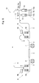
- an ink circulation system 1 in accordance with a first embodiment of the present invention includes an inkjet head 2, an ink cartridge 3, a supply flow passage 4, a return flow passage 5, a tube pump 6, a tube pump 7, a pressurization bellows unit 8, a pressure reduction bellows unit 9, a pressurization regulator 10, a pressure reducing regulator 11, and a high speed circulating flow passage 12.
- the inkjet head 2 is a head for ejecting ink droplets. Therefore, as shown in Fig. 2 , the inkjet head 2 is formed with a number of nozzles 15 and a common ink flow passage 16 which is communicated with all the nozzles 15.
- the common ink flow passage 16 is a flow passage through which ink supplied from the ink cartridge 3 to the inkjet head 2 is flowed.
- the common ink flow passage 16 is communicated with all the nozzles 15 which are formed in the inkjet head 2 and the ink supplied to the inkjet head 2 from the ink cartridge 3 is distributed and supplied to the respective nozzles 15.
- One end of the common ink flow passage 16 is formed with an inlet 16a which introduces the ink supplied from the supply flow passage 4 into the common ink flow passage 16 and the other end of the common ink flow passage 16 is formed with an outlet 16b through which the ink supplied to the common ink flow passage 16 is discharged to the return flow passage 5.
- the inlet 16a and the outlet 16b are formed at both ends of the common ink flow passage 16. Therefore, the ink introduced through the inlet 16a is flowed from the one end of the common ink flow passage 16 to the other end and is discharged through the outlet 16b.
- Each of the nozzles 15 ejects the ink supplied from the common ink flow passage 16 as an ink droplet having a predetermined quantity.
- Each nozzle 15 is formed in a minute tube-like shape.
- Each nozzle 15 is formed with a chamber 15a whose diameter partially becomes large so as to be bulged.
- a piezoelectric element not shown for pressurizing the inside of the chamber 15a is attached in the chamber 15a. When the piezoelectric element is driven to pressurize the inside of the chamber 15a, a predetermined quantity of ink is pushed out from the chamber 15a and an ink droplet having a predetermined size is ejected from a tip end of each nozzle 15.
- a head value of the ink and the like are adjusted so as to prevent leakage of the ink from each nozzle 15 and the ink supplied to the nozzle 15 is held in a negative pressure state.
- the head value of the ink and the like are adjusted to form the ink supplied to each nozzle 15 in a meniscus having a predetermined shape.
- the inkjet head 2 structured as described above is mounted on a carriage not shown which is attached so as to be movable in a scan direction. Further, the inkjet head 2 ejects ink droplets when the carriage is moved in the scan direction and thereby an image or the like is printed on a recording medium which is placed on a platen not shown.
- the ink cartridge 3 is an ink container filled with ink which is supplied to the inkjet head 2.
- the ink cartridge 3 is disposed at an arbitrary height irrespective of a designated head value.
- the supply flow passage 4 is structured of a long and thin tube-like member (tube), which communicates the ink cartridge 3 with the inkjet head 2 and the ink filled in the ink cartridge 3 is supplied to the inkjet head 2 through the supply flow passage 4.
- the tube pump 6, the pressurization bellows unit 8 and the pressurization regulator 10 are attached in the supply flow passage 4 between the ink cartridge 3 and the inkjet head 2.
- the supply flow passage 4 is structured of a flow passage which communicates the ink cartridge 3 with the tube pump 6, a flow passage which communicates the tube pump 6 with the pressurization bellows unit 8, a flow passage which communicates the pressurization bellows unit 8 with the pressurization regulator 10, and a flow passage which communicates the pressurization regulator 10 with the inkjet head 2.
- the return flow passage 5 is structured of a long and thin tube-like member (tube), which communicates the inkjet head 2 with the ink cartridge 3 and the ink filled in the inkjet head 2 is returned to the ink cartridge 3 through the return flow passage 5.
- the pressure reducing regulator 11, the pressure reduction bellows unit 9 and the tube pump 7 are attached in the return flow passage 5 between the inkjet head 2 and the ink cartridge 3. Therefore, the return flow passage 5 is structured of a flow passage which communicates the inkjet head 2 with the pressure reducing regulator 11, a flow passage which communicates the pressure reducing regulator 11 with the pressure reduction bellows unit 9, a flow passage which communicates the pressure reduction bellows unit 9 with the tube pump 7, and a flow passage which communicates the tube pump 7 with the ink cartridge 3.
- the tube pump 6 is a liquid feeding device which sends the ink in the supply flow passage 4 toward the inkjet head 2.
- the tube pump 6 is structured of a built-in tube not shown and a built-in roller which is rotated while crushing the tube.
- the supply flow passage 4 is connected to both ends of the built-in tube. Therefore, the built-in roller is rotated while crushing the built-in tube of the tube pump 6 and thereby the ink supplied to the supply flow passage 4 from the ink cartridge 3 is forcibly sent to the inkjet head 2 side.
- the tube pump 6 is capable of adjusting a flow rate of the ink flowing through the supply flow passage 4 by adjusting the rotation number of the built-in roller.
- the tube pump 7 is a liquid feeding device which sends the ink in the return flow passage 5 toward the ink cartridge 3.
- the tube pump 7 is structured of a built-in tube not shown and a built-in roller which is rotated while crushing the built-in tube.
- the return flow passage 5 is connected to both ends of the built-in tube. Therefore, the built-in roller is rotated while crushing the built-in tube of the tube pump 7 and thereby the ink discharged from the common ink flow passage 16 to the return flow passage 5 is forcibly sent to the ink cartridge 3 side.
- the tube pump 7 is capable of adjusting a flow rate of the ink flowing through the return flow passage 5 by adjusting the rotation number of the built-in roller.
- the pressurization bellows unit 8 is structured of a metal bellows 8a structured of a bellows-like expansion and contraction pipe and a micro switch 8b which is provided on an upper side of the metal bellows 8a and whose "ON/OFF" is switched by expansion and contraction of the metal bellows 8a.
- the pressurization bellows unit 8 is disposed between the tube pump 6 and the pressurization regulator 10.
- the micro switch 8b is interlocked with the tube pump and, when the metal bellows 8a is expanded, the micro switch 8b becomes an "OFF” position and, when the metal bellows 8a is contracted, the micro switch 8b becomes an "ON” position.
- the metal bellows 8a is, for example, structured of stainless steel.
- the metal bellows 8a is expanded by forcibly sending ink into its inside from the tube pump 6.
- the micro switch 8b is turned “OFF” and drive of the tube pump 6 is stopped.
- the expanded metal bellows 8a is contracted by its restoring force and thus the ink flowing through the supply flow passage 4 is pressurized.
- the micro switch 8b is turned “ON” and the drive of the tube pump 6 is started again. In this manner, the ink flowing through the supply flow passage 4 is pressurized by expansion and contraction of the metal bellows 8a.
- the pressurization bellows unit 8 is capable of adjusting a pressure value for pressurizing the ink flowing through the supply flow passage 4 by adjusting a spring constant of the metal bellows 8a.
- the pressurization bellows unit 8 pressurizes the ink flowing through the supply flow passage 4, for example, in a range from 5000 to 20000 Pa ( ⁇ from 500 to 2000mm H 2 O) by setting the spring constant of the metal bellows 8a.
- the pressure reduction bellows unit 9 is structured of a metal bellows 9a structured of a bellows-like expansion and contraction pipe and a micro switch 9b which is provided on an upper side of the metal bellows 9a and whose "ON/OFF" is switched by expansion and contraction of the metal bellows 9a.
- the pressure reduction bellows unit 9 is disposed between the pressure reducing regulator 11 and the tube pump 7.
- the micro switch 9b is interlocked with the tube pump and, when the metal bellows 9a is expanded, the micro switch 9b becomes an "ON" position and, when the metal bellows 9a is contracted, the micro switch 9b becomes an "OFF" position.
- the metal bellows 8a is, for example, structured of stainless steel.
- the metal bellows 9a is contracted by forcibly sucking the ink by the tube pump 7.
- the micro switch 9b is turned “OFF” and the drive of the tube pump 7 is stopped.
- the contracted metal bellows 9a is expanded by its restoring force and the ink flowing through the return flow passage 5 is depressurized.
- the micro switch 9b is turned “ON” and the drive of the tube pump 7 is started again. In this manner, the ink flowing through the return flow passage 5 is depressurized by expansion and contraction of the metal bellows 9a.
- the pressure reduction bellows unit 9 is capable of adjusting a pressure value for depressurizing the ink flowing through the return flow passage 5 by adjusting a spring constant of the metal bellows 9a.
- the pressure reduction bellows unit 9 depressurizes the ink flowing through the return flow passage 5, for example, in a range from -5000 to -20000 Pa by setting a spring constant of the metal bellows 9a.
- the pressurization regulator 10 is disposed between the pressurization bellows unit 8 and the inkjet head 2 and is a regulator so as to maintain an inlet 16a of the common ink flow passage 16 at a predetermined set pressure or more.
- the pressurization regulator 10 is also referred to as a pressurization damper.
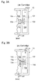
- Fig. 3A and Fig. 3B are views showing a model of the pressurization regulator.
- Fig. 3A shows a state that a valve is closed and
- Fig. 3B shows a state that the valve is opened.
- the pressurization regulator 10 is formed of a first pressure chamber 10a into which the ink supplied from the ink cartridge 3 is flowed, and a second pressure chamber 10b which is covered by a diaphragm 10c and from which the ink is flowed out to the inlet 16a of the common ink flow passage 16. An outside of the diaphragm 10c covering the second pressure chamber 10b is exposed to the atmospheric pressure.
- the pressurization regulator 10 is formed with a through hole 10d which communicates the first pressure chamber 10a with the second pressure chamber 10b to flow the ink from the first pressure chamber 10a to the second pressure chamber 10b.
- a valve element 10e for opening or closing the through hole 10d is inserted into the through hole 10d.
- One end of the valve element 10e is connected with the diaphragm 10c and is movably held by the diaphragm 10c and its other end is formed with a valve 10f for closing the through hole 10d from the first pressure chamber 10a side.
- an O-ring 10h for sealing is attached at a position corresponding to the valve 10f.
- the valve element 10e is urged by a pressure control spring 10g in a direction so that the valve 10f closes the through hole 10d.
- the pressure control spring 10g is capable of being expanded and contracted by an adjusting screw not shown.
- a pressure of the ink flowing into the first pressure chamber 10a is set to be "P1in”
- a pressure of the ink flowing out from the second pressure chamber 10b is set to be “P1out”
- an area of the diaphragm 10c is set to be “A1”
- an urging force of the pressure control spring 10g is set to be “F1”.
- the pressure "P1out” of the ink flowing out from the second pressure chamber 10b is set to be a negative pressure so that a shape of the ink supplied to each nozzle is formed in a predetermined meniscus shape.
- a force obtained by multiplying the "P1out” by the area “A1” is a force acting in a direction for opening the valve element 10e (right direction in Figs. 3A and 3B ).
- the urging force "F1" of the pressure control spring 10g is a force acting in a direction for closing the valve element 10e (left direction in Figs. 3A and 3B ).
- the pressure "P1in” in order to control the pressure "P1in” in a constant pressure by opening and closing the valve 10f, the pressure “P1in” is required to be not less than the pressure "P1out” and it is preferable that the pressure “P1in” is set to be a sufficiently higher value than the pressure "P1out".
- the pressure "P1out” which is maintained by the pressurization regulator 10 becomes a set pressure of the pressurization regulator 10.
- the set pressure of the pressurization regulator 10 is determined based on the urging force "F1" of the pressure control spring 10g and the area “A1" of the diaphragm 10c and thus the set pressure of the pressurization regulator 10 is adjusted by adjusting the strength of the pressure control spring 10g.
- the set pressure of the pressurization regulator 10 is set to be a center value "+ ⁇ " (first pressure) of the designated head value by adjusting the strength of the pressure control spring 10g.
- the pressure "P1out" of the ink outputted from the second pressure chamber 10b by an open-and-close operation of the valve 10f is maintained at the center value "+ ⁇ " of the designated head value and thus an ink pressure of the inlet 16a communicated with the second pressure chamber 10b is also maintained at the center value "+ ⁇ " of designated head value.
- the pressure reducing regulator 11 is disposed between the pressure reduction bellows unit 9 and the inkjet head 2 and is a regulator so that an outlet 16b of the common ink flow passage 16 is maintained at a predetermined set pressure or less.
- the pressure reducing regulator 11 is also referred to as a pressure reducing damper.
- Fig. 4A and Fig. 4B are views showing a model of the pressure reducing regulator.
- Fig. 4A shows a state that a valve is closed and
- Fig. 4B shows a state that the valve is opened.
- the pressure reducing regulator 11 is formed of a first pressure chamber 11a which is covered by a diaphragm 11c and into which the ink returned from the outlet 16b of the inkjet head 2 is flowed, and a second pressure chamber 11b from which the ink is flowed out to the ink cartridge 3.
- An outside of the diaphragm 11c covering the first pressure chamber 11a is exposed to the atmospheric pressure.
- the pressure reducing regulator 11 is formed with a through hole 11d which communicates the first pressure chamber 11a with the second pressure chamber 11b so that the ink is flowed to the second pressure chamber 11b from the first pressure chamber 11a, and the pressure reducing regulator 11 is provided with a valve element 11e for opening and closing the through hole 11d.
- One end of the valve element 11e is connected with the diaphragm 11c and is movably held by the diaphragm 11c and its other end is formed with a valve 11f for closing the through hole 11d from the first pressure chamber 11a side.
- an O-ring 11h for sealing is attached at a position corresponding to the valve 11f.
- the valve element 11e is urged by a pressure control spring 11g in a direction so that the valve 11f opens the through hole 11d.
- the pressure control spring 11g is capable of being expanded and contracted by an adjusting screw not shown.
- a pressure of the ink flowing into the first pressure chamber 11a is set to be "P2in”
- a pressure of the ink flowing out from the second pressure chamber 11b is set to be “P2out”
- an area of the diaphragm 11c is set to be “A2”
- an urging force of the pressure control spring 11g is set to be "F2”.
- the pressure "P2in” of the ink flowing into the first pressure chamber 11a is set to be a negative pressure so that a shape of the ink supplied to each nozzle is formed in a predetermined meniscus shape.
- a force obtained by multiplying the "P2in” by the area “A2” is a force acting in a direction for closing the valve element 11e (right direction in Figs. 4A and 4B ).
- the urging force "F2" of the pressure control spring 11g is a force acting in a direction for opening the valve element 11e (left direction in Figs. 4A and 4B ).
- the pressure "P2out” is required to be not more than the pressure "P2in” and it is preferable that the pressure "P2out” is set to be a sufficiently lower value than the pressure "P2in”.
- the pressure "P2in” which is maintained by the pressure reducing regulator 11 becomes a set pressure of the pressure reducing regulator 11.
- the set pressure of the pressure reducing regulator 11 is determined based on the urging force "F2" of the pressure control spring 11g and the area “A2" of the diaphragm 11c and thus the set pressure of the pressure reducing regulator 11 is adjusted by adjusting the strength of the pressure control spring 11g.
- the set pressure of the pressure reducing regulator 11 is set to be a center value "- ⁇ " (second pressure) of the designated head value by adjusting the strength of the pressure control spring 11g.
- the pressure "P2in” of the ink inputted into the first pressure chamber 11a by an open-and-close operation of the valve 11f is maintained at the center value "- ⁇ " of the designated head value and thus an ink pressure of the outlet 16b communicated with the first pressure chamber 11a is also maintained at the center value "- ⁇ " of designated head value.
- the set pressure of the pressurization regulator 10 is set to be the center value "+ ⁇ " of the designated head value and the set pressure of the pressure reducing regulator 11 is set to be the center value "- ⁇ " of the designated head value and thereby a differential pressure of "2 ⁇ " is generated between both end parts of the common ink flow passage 16 of the inkjet head 2.
- the differential pressure "2 ⁇ " generated by the pressurization regulator 10 and the pressure reducing regulator 11 is set to be a value so that ink is circulated to the extent that fine particles contained in liquid component of the ink are agitated. Further, it is preferable that the differential pressure "2 ⁇ ” is set to be a value within a range of a shape keeping strength of meniscus in which the meniscus shape of the ink formed in each nozzle 15 is not broken.
- the differential pressure "2 ⁇ " generated between both end parts of the common ink flow passage 16 by the pressurization regulator 10 and the pressure reducing regulator 11 is, for example, set to be 100 Pa.
- the set pressure of the pressurization regulator 10 is the center value +50 Pa of the designated head value and the set pressure of the pressure reducing regulator 11 is the center value -50 Pa of the designated head value.
- the pressurization regulator 10 is required to set the pressure "P1in” of the ink flowing into the first pressure chamber 10a to be not less than the pressure "P1out” of the ink outputted from the second pressure chamber 10b and thus a pressure generated by the pressurization bellows unit 8 is, for example, set to be in a range from 5000 to 20000 Pa. Therefore, the pressure "P1in” of the ink which is flowed into the first pressure chamber 10a becomes in a range from 5000 to 20000 Pa.
- the pressure reducing regulator 11 is required to set the pressure "P2out” of the ink outputted from the second pressure chamber 11b to be not more than the pressure "P2in” of the ink flowed into the first pressure chamber 11a and thus a pressure generated by the pressure reduction bellows unit 9 is, for example, set to be in a range from -5000 to -20000 Pa. Therefore, the pressure "P2out" of the ink which is flowed out from the second pressure chamber 11b becomes in a range from -5000 to -20000 Pa.
- a pressure applied to the ink is varied due to hysteresis of the ON/OFF switching of the micro switch 8b.
- the pressurization regulator 10 maintains the pressure "P1out” of the ink outputted from the second pressure chamber 10b at the center value "+ ⁇ " of the designated head value. Therefore, even when pressure variation is occurred by the pressurization bellows unit 8, the pressure of the inlet 16a is maintained at the center value "+ ⁇ " of the designated head value.
- a pressure applied to the ink is varied due to hysteresis of the ON/OFF switching of the micro switch 9b.
- the pressure reducing regulator 11 maintains the pressure "P2in” of the ink flowed into the first pressure chamber 11a at the center value "- ⁇ " of the designated head value. Therefore, even when pressure variation by the pressure reduction bellows unit 9 is occurred, the pressure of the outlet 16b is maintained at the center value "- ⁇ " of the designated head value.
- the high speed circulating flow passage 12 is structured of a long and thin tube-like member (tube), by which the inkjet head 2, the pressurization regulator 10 and the pressure reducing regulator 11 are bypassed.
- the high speed circulating flow passage 12 is a flow passage for forcibly circulating ink at a high speed in an ink flow passage passing through the ink cartridge 3, the tube pump 6, the tube pump 7, the pressurization bellows unit 8 and the pressure reduction bellows unit 9.
- the high speed circulating flow passage 12 is, similarly to the supply flow passage 4 and the return flow passage 5, structured of a long and thin tube-like member (tube).
- One end of the high speed circulating flow passage 12 is connected between the pressurization bellows unit 8 and the pressurization regulator 10 in the supply flow passage 4, and the other end of the high speed circulating flow passage 12 is connected between the pressure reduction bellows unit 9 and the pressure reducing regulator 11 in the return flow passage 5.
- the high speed circulating flow passage 12 is capable of being opened and closed by an electromagnetic valve not shown.
- ink is capable of bypassing the inkjet head 2, the pressurization regulator 10 and the pressure reducing regulator 11 and circulating through the ink flow passage passing through the ink cartridge 3, the tube pump 6, the tube pump 7, the pressurization bellows unit 8 and the pressure reduction bellows unit 9.
- An operation of the ink circulation system 1 includes a normal circulating operation which is performed at a normal time and a high-speed circulating operation and they will be described below successively.
- the normal circulating operation is performed by driving the tube pump 6, the tube pump 7, the micro switch 8b of the pressurization bellows unit 8, and the micro switch 9b of the pressure reduction bellows unit 9 through a control section not shown.
- the high speed circulating flow passage 12 is closed.
- the ink in the supply flow passage 4 is sent toward the inkjet head 2 by the tube pump 6. Further, the ink which is sent out by the tube pump 6 is pressurized, for example, in a range from 5000 to 20000 Pa by the pressurization bellows unit 8. Therefore, the ink which is filled in the ink cartridge 3 is pressure-fed toward the inlet 16a and the ink on the inlet 16a side of the inkjet head 2 in the supply flow passage 4 is pressurized, for example, in a range from 5000 to 20000 Pa.
- the pressurization regulator 10 the ink which is pressure-fed by the tube pump 6 and the pressurization bellows unit 8 is flowed into the first pressure chamber 10a. Then, when the pressure "P1out" of the ink which is flowed out from the second pressure chamber 10b to the inlet 16a becomes not more than the center value "+ ⁇ " of the designated head value, the valve 10f opens the through hole 10d. As a result, the ink flowed into the first pressure chamber 10a is flowed out from the second pressure chamber 10b and supply of the ink to the inlet 16a is performed.
- the pressure "P1out" of the ink which is flowed out from the second pressure chamber 10b to the inlet 16a becomes higher than the center value "+ ⁇ " of the designated head value, the valve 10f closes the through hole 10d. As a result, flow of the ink from the first pressure chamber 10a to the second pressure chamber 10b is shut off and the supply of the ink to the inlet 16a is stopped.
- the ink supplied to the inlet 16a is maintained at the center value "+ ⁇ " of the designated head value, which is the set pressure, by an open-and-close operation of the valve 10f based on the relationship between the pressure "P1out" of the ink flowing out from the second pressure chamber 10b to the inlet 16a and the center value of the designated head value.
- the ink in the return flow passage 5 is sent out to the ink cartridge 3 side by the tube pump 7 and the pressure on the outlet 16b side of the inkjet head 2 in the return flow passage 5 is depressurized, for example, in the range from -5000 to -20000 Pa by the pressure reduction bellows unit 9.
- the ink is sent out by the tube pump 7 and the pressure reduction bellows unit 9 and thereby the pressure of the second pressure chamber 11b is lowered. Then, when the pressure "P2in" of the ink which is flowed into the first pressure chamber 11a from the outlet 16b becomes not less than the center value "- ⁇ " of the designated head value, the valve 11f opens the through hole 11d. Therefore, the ink discharged from the outlet 16b is flowed into the second pressure chamber 11b through the first pressure chamber 11a and is sent out by the tube pump 7 and the pressure reduction bellows unit 9.
- ink is flowed through the common ink flow passage 16 from the inlet 16a to the outlet 16b by the differential pressure of "2 ⁇ " generated between the inlet 16a and the outlet 16b.
- the ink stored in the ink cartridge 3 is circulated through the supply flow passage 4, the tube pump 6, the supply flow passage 4, the pressurization bellows unit 8, the supply flow passage 4, the pressurization regulator 10, the supply flow passage 4, the common ink flow passage 16 of the inkjet head 2, the return flow passage 5, the pressure reducing regulator 11, the return flow passage 5, the pressure reduction bellows unit 9, the return flow passage 5, the tube pump 7, the return flow passage 5 and the ink cartridge 3.
- the high-speed circulating operation is an operation by which ink is filled in the ink flow passage or, by which composition such as fine particles contained in the ink is surly agitated.
- the high-speed circulating operation is performed periodically or at an arbitrary time, for example, when the power of the inkjet printer is turned on or when maintenance is performed.
- an electromagnetic valve for opening and closing the high speed circulating flow passage 12 is driven and controlled to open the high speed circulating flow passage 12.
- the ink is capable of bypassing the inkjet head 2, the pressurization regulator 10 and the pressure reducing regulator 11 and circulating through the ink flow passage passing through the ink cartridge 3, the tube pump 6, the tube pump 7, the pressurization bellows unit 8 and the pressure reduction bellows unit 9.
- the tube pump 6, the tube pump 7, the micro switch 8b of the pressurization bellows unit 8, and the micro switch 9b of the pressure reduction bellows unit 9 are driven and controlled.
- the tube pump 6 and the tube pump 7 are rotated at a higher speed than the normal circulating operation.
- ink is circulated at a high speed through the ink flow passage passing through the ink cartridge 3, the tube pump 6, the tube pump 7, the pressurization bellows unit 8 and the pressure reduction bellows unit 9.
- composition such as fine particles contained in the ink is agitated sufficiently in the ink flow passage passing through the ink cartridge 3, the tube pump 6, the tube pump 7, the pressurization bellows unit 8 and the pressure reduction bellows unit 9 and its sedimentation and precipitation are restrained.
- the differential pressure of both ends of the high speed circulating flow passage 12 becomes large, the differential pressure similar to the normal circulating time can be supplied to the pressurization regulator 10 and the pressure reducing regulator 11.
- the high speed circulating flow passage 12 is opened all the time, the bypassed circulating flow passage is strongly agitated all the time and, in addition, the differential pressure at the normal circulating time is applied to the inkjet head 2 side from the high speed circulating flow passage 12 and thus it is suitable for the ink which is further easily precipitated.
- ink is supplied from the ink cartridge 3 to the inlet 16a of the common ink flow passage 16 through the supply flow passage 4 and the ink is returned from the outlet 16b of the common ink flow passage 16 to the ink cartridge 3 through the return flow passage 5. Therefore, the ink which is stored in the ink cartridge 3 can be circulated through the ink flow passage passing through the ink cartridge 3, the supply flow passage 4, the common ink flow passage 16 and the return flow passage 5.
- the ink on the inkjet head 2 side in the supply flow passage 4 is pressurized by the tube pump 6 and the pressurization bellows unit 8 and the ink on the ink cartridge 3 side in the return flow passage 5 is depressurized by the tube pump 7 and the pressure reduction bellows unit 9 and thereby a differential pressure is generated between both end parts of the common ink flow passage 16. Therefore, the ink can be circulated in the ink flow passage passing through the ink cartridge 3, the supply flow passage 4, the common ink flow passage 16 and the return flow passage 5 and thus composition such as fine particles contained in the ink is agitated and sedimentation and precipitation of the composition such as the fine particles are restrained. Further, air bubbles stagnant in the piping can be flowed to remove appropriately.
- the pressurization regulator 10 is provided between the pressurization bellows unit 8 and the inlet 16a of the common ink flow passage 16, even when a pressure generated by the tube pump 6 and the pressurization bellows unit 8 is varied, the pressure of the ink of the inlet 16a in the common ink flow passage 16 can be maintained at the center value "+ ⁇ " of the designated head value.
- the pressure reducing regulator 11 is provided between the pressure reduction bellows unit 9 and the outlet 16b of the common ink flow passage 16, even when a pressure generated by the tube pump 7 and the pressure reduction bellows unit 9 is varied, the pressure of the ink of the outlet 16b in the common ink flow passage 16 can be maintained at the center value "- ⁇ " of the designated head value.
- a pressure of the second pressure chamber 10b communicated with the inlet 16a is normally a negative pressure and thus the diaphragm 10c is drawn to the second pressure chamber 10b side by the outside under atmospheric pressure and a force in a direction for opening the valve element 10e is generated.
- a force applied to the diaphragm 10c by an ink pressure of the second pressure chamber 10b which presses the valve element 10e in an open direction becomes smaller than a force of the pressure control spring 10g which presses the valve element 10e in a close direction, the valve element 10e closes the through hole 10d and supply of the ink is stopped.
- a pressure of the first pressure chamber 11b communicated with the outlet 16b is normally a negative pressure and thus the diaphragm 11c is drawn to the first pressure chamber 11a side by the outside under atmospheric pressure and a force in a direction for closing the valve element 11e is generated.
- a force applied to the diaphragm 11c by an ink pressure of the first pressure chamber 11a which presses the valve element 11e in a close direction becomes larger than a force of the pressure control spring 11g which presses the valve element 11e in an open direction, the valve element 11e closes the through hole 10d and supply of the ink is stopped.
- the set pressure of the pressurization regulator 10 is set to be the center value "+ ⁇ " of the designated head value and the set pressure of the pressure reducing regulator 11 is set to be the center value "- ⁇ " of the designated head value. Therefore, an average pressure of the common ink flow passage 16 can be brought close to the center value of the designated head value and thus the meniscus of the ink formed in each nozzle 15 can be prevented from being broken.
- the tube pump 6 and the pressurization bellows unit 8 are provided in the supply flow passage 4, ink on the inlet 16a side in the common ink flow passage 16 can be pressurized and, since the tube pump 7 and the pressure reduction bellows unit 9 are provided in the return flow passage 5, ink on the outlet 16b side in the common ink flow passage 16 can be depressurized. Therefore, a predetermined differential pressure is generated between both end parts of the common ink flow passage 16 to circulate the ink with a simple structure such as a bellows unit or a tube pump.
- the ink cartridge 3 can be disposed at an arbitrary height position by using the pressurization bellows unit 8 and the pressure reduction bellows unit 9.
- the ink stored in the ink cartridge 3 is used up, the ink is not supplied to the pressurization bellows unit 8 and thus the micro switch 8b is not switched. Therefore, a state that the ink in the ink cartridge 3 has been used up can be detected by monitoring the switching of the micro switch 8b.
- FIG. 5 is a schematic structure view showing an ink circulation system in accordance with the second embodiment of the present invention.
- the ink circulation system 21 in accordance with the second embodiment includes an inkjet head 2, an ink cartridge 3, a supply flow passage 4, a return flow passage 5, a pressurization regulator 10, a pressure reducing regulator 11, a high speed circulating flow passage 12, and a differential pressure generating pump 22.
- the differential pressure generating pump 22 is structured of a so-called centrifugal pump, which forcibly sends out ink from an input port to an output port to generate a differential pressure between the input port and the output port.
- the input port into which the ink is inputted is connected with the ink cartridge 3 and the output port from which the ink is outputted is connected with the pressurization regulator 10.
- the differential pressure generating pump 22 forcibly sends out ink to the pressurization regulator 10 and thereby the supply flow passage 4 on the pressurization regulator 10 side is pressurized, and ink is sucked from the ink cartridge 3 by the differential pressure generating pump 22 to depressurize the return flow passage 5. In this manner, a differential pressure is generated between an inlet 16a and an outlet 16b of a common ink flow passage 16.
- a drive force of the differential pressure generating pump 22 is adjusted and thereby a pressure "P1in” of the ink which is pressure-fed into a first pressure chamber 10a of the pressurization regulator 10 is, for example, set in a range from 5000 to 20000 Pa and a pressure "P2out” of the ink which is sucked from a second pressure chamber 11b of the pressure reducing regulator 11 is, for example, set in a range from -5000 to -20000 Pa.
- a high-speed circulating operation is basically similar to the first embodiment and thus only a normal circulating operation will be described below.
- the differential pressure generating pump 22 is driven by a control section not shown.
- the ink on the inlet 16a side of the inkjet head 2 in the supply flow passage 4 is, for example, pressurized in a range from 5000 to 20000 Pa and a pressure on the outlet 16b side of the inkjet head 2 in the return flow passage 5 is, for example, depressurized in a range from -5000 to -20000 Pa.
- the ink of the inlet 16a is maintained at a pressure of the center value "+ ⁇ " of the designated head value by the pressurization regulator 10 and the ink of the outlet 16b is maintained at a pressure of the center value "- ⁇ " of the designated head value by the pressure reducing regulator 11.
- the ink circulation system 21 in accordance with the second embodiment the following operation-effects are obtained together with the operation-effects of the above-mentioned ink circulation system.
- a differential pressure is also generated between both end parts of the common ink flow passage 16 by the differential pressure generating pump 22. Therefore, the ink is circulated in the ink flow passage and thus composition such as fine particles contained in the ink can be agitated and sedimentation and precipitation of the composition such as the fine particles are restrained. Further, air bubbles stagnant in the piping can be flowed to remove appropriately.
- a pressure can be applied to the ink flow passage by the differential pressure generating pump 22 and thus, when the pressure generated by the differential pressure generating pump 22 is adjusted, a pressure of the center value of the designated head value can be applied to the inkjet head 2 without being restricted by a height position of the ink cartridge 3. Therefore, the ink cartridge 3 can be disposed at an arbitrary height position by using the differential pressure generating pump 22.
- FIG. 6 is a schematic structure view showing an ink circulation system in accordance with the third embodiment of the present invention.
- an ink circulation system 31 in accordance with the third embodiment includes an inkjet head 2, an ink cartridge 3, a supply flow passage 4, a return flow passage 5, a tube pump 6, a pressurization bellows unit 8, a pressurization regulator 10, a high speed circulating flow passage 12, and a passive regulator 32.
- the passive regulator 32 relaxes pressure variation of an outlet 16b in a common ink flow passage 16.
- a pressure adjusting means comprised of the tube pump 6, the pressurization bellows unit 8 and the pressurization regulator 10 is provided between the inkjet head 2 and the ink cartridge 3 in the supply flow passage 4. Therefore, an inlet 16a of the common ink flow passage 16 can be maintained at the center value "+ ⁇ " of the designated head value.
- the passive regulator 32 is provided between the inkjet head 2 and the ink cartridge 3 in the return flow passage 5 and a pressure adjusting means such as a tube pump, a pressure reduction bellows unit and a pressure reducing regulator is not provided in the return flow passage 5.
- a relative height of the ink cartridge to the inkjet head 2 is set so that the head value of the inkjet head 2 becomes the center value "- ⁇ " of the designated head value. In this manner, the outlet 16b of the common ink flow passage 16 is maintained at the center value "- ⁇ " of the designated head value.
- a high-speed circulating operation is basically similar to the first embodiment and thus only a normal circulating operation will be described below.
- the tube pump 6 and a micro switch 8b of the pressurization bellows unit 8 are driven by a control section not shown.
- the high speed circulating flow passage 12 is closed.
- ink in the supply flow passage 4 is sent to the inkjet head 2 side by the tube pump 6 and ink of the inlet 16a side of the inkjet head 2 in the supply flow passage 4 is pressurized, for example, in a range from 5000 to 20000 Pa by the pressurization bellows unit 8. Further, the ink of the inlet 16a is maintained at a pressure of the center value "+ ⁇ " of the designated head value by the pressurization regulator 10.
- the inkjet head 2 and the ink cartridge 3 are disposed so that a height difference between the inkjet head 2 and the ink cartridge 3 is set to be the center value "- ⁇ " of the designated head value and thus the ink of the outlet 16b is maintained at a pressure of the center value "- ⁇ " of the designated head value.
- the ink circulation system 31 in accordance with the third embodiment the following operation-effects are obtained in addition to the operation-effects of the above-mentioned ink circulation systems.
- the ink circulation system 31 in accordance with the third embodiment since the ink cartridge 3 is disposed at a lower position with respect to the inkjet head 2, ink on the outlet 16b side in the return flow passage 5 is depressurized and thus a differential pressure is generated between both end parts of the common ink flow passage 16. Therefore, the ink can be circulated through the ink flow passage.
- the ink cartridge 3 is disposed so that a pressure of the ink on the inkjet head 2 side in the return flow passage 5 becomes not more than the center value "- ⁇ " of the designated head value and thus the pressure of the ink in the outlet 16b can be maintained at the center value "- ⁇ " of the designated head value by the passive regulator 32. Therefore, an average pressure of the common ink flow passage 16 can be brought close to the center value of the designated head value and thus the meniscus of the ink formed in each nozzle 15 of the inkjet head 2 can be prevented from being broken.
- FIG. 7 is a schematic structure view showing an ink circulation system in accordance with the fourth embodiment of the present invention.
- an ink circulation system 41 in accordance with the fourth embodiment includes an inkjet head 2, an ink cartridge 3, a supply flow passage 4, a return flow passage 5, a tube pump 6, a tube pump 7, a pressurization bellows unit 8, a pressurization regulator 10, a high speed circulating flow passage 12 and a passive regulator 32.
- the pressure reduction bellows unit 9 of the ink circulation system 1 in accordance with the first embodiment is not used and a passive regulator 32 is provided instead of the pressure reducing regulator 11.
- a high-speed circulating operation is basically similar to the first embodiment and thus only a normal circulating operation will be described below.
- the tube pump 6, the tube pump 7, the micro switch 8b of the pressurization bellows unit 8 are driven by a control section not shown.
- the high speed circulating flow passage 12 is closed.
- ink in the supply flow passage 4 is sent toward the inkjet head 2 side by the tube pump 6 and ink on the inlet 16a side of the inkjet head 2 in the supply flow passage 4 is pressurized, for example, in a range from 5000 to 20000 Pa by the pressurization bellows unit 8. Further, the ink of the inlet 16a is maintained at a pressure of the center value "+ ⁇ " of the designated head value by the pressurization regulator 10.
- ink in the return flow passage 5 is sent out toward the ink cartridge 3 by the tube pump 7.
- a pressure loss is occurred in the ink flowing through the common ink flow passage 16 and thus a differential pressure due to the pressure loss is generated. Therefore, a drive force of the tube pump 7 is adjusted and thereby a pressure of the center value "- ⁇ " of the designated head value is generated in the outlet 16b.
- the flow rate of the ink by the tube pump 7 is maintained to be constant.
- ink is flowed from the inlet 16a to the outlet 16b through the common ink flow passage 16 in a state that a differential pressure of "2 ⁇ " is generated between the inlet 16a and the outlet 16b. Therefore, ink stored in the ink cartridge 3 is circulated through the supply flow passage 4, the tube pump 6, the supply flow passage 4, the pressurization bellows unit 8, the supply flow passage 4, the pressurization regulator 10, the supply flow passage 4, the common ink flow passage 16 of the inkjet head 2, the return flow passage 5, the passive regulator 32, the return flow passage 5, the tube pump 7, the return flow passage 5 and the ink cartridge 3.
- the ink circulation system 41 in accordance with the fourth embodiment the following operation-effects are obtained in addition to the operation-effects of the above-mentioned ink circulation systems.
- a pressure of the center value "- ⁇ " of the designated head value is generated in the outlet 16b by the pressure loss of the ink due to driving of the tube pump 7 and thus the cost of the system can be reduced while the ink is circulated appropriately.
- FIG. 8 is a schematic structure view showing an ink circulation system in accordance with the fifth embodiment of the present invention.
- an ink circulation system 51 in accordance with the fifth embodiment includes an inkjet head 2, an ink cartridge 3, a supply flow passage 4, a return flow passage 5, a tube pump 6, a tube pump 7, a pressurization bellows unit 8, a pressure reduction bellows unit 9, a pilot air type pressurization regulator 52, a pilot air type pressure reducing regulator 53, and a high speed circulating flow passage 12.
- the pressurization regulator 10 of the ink circulation system 1 in accordance with the first embodiment is replaced with the pilot air type pressurization regulator 52 and the pressure reducing regulator 11 is replaced with the pilot air type pressure reducing regulator 53.
- the pilot air type pressurization regulator 52 is disposed between the pressurization bellows unit 8 and the inkjet head 2 and maintains the inlet 16a of the common ink flow passage 16 at a pressure not less than a predetermined pressure.
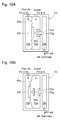
- Fig. 9A and Fig. 9B are views showing a model of a pilot air type pressurization regulator.
- Fig. 9A shows a state that a valve is closed and
- Fig. 9B shows a state that the valve is opened.
- the pilot air type pressurization regulator 52 is formed with a first pressure chamber 52a into which ink supplied from the ink cartridge 3 is flowed, a second pressure chamber 52b from which ink is flowed out to an inlet 16a of the common ink flow passage 16, and a third pressure chamber 52c into which pilot air having a set air pressure is flowed.
- the second pressure chamber 52b and the third pressure chamber 52c are partitioned by a diaphragm 52d and a through hole 52e is formed between the first pressure chamber 52a and the second pressure chamber 52b so as to communicate with each other and so that ink is flowed from the first pressure chamber 52a to the second pressure chamber 52b.
- a valve element 52f for opening and closing the through hole 52e is inserted into the through hole 52e.
- One end of the valve element 52f is connected with the diaphragm 52d and is movably held by the diaphragm 52d and its other end is formed with a valve 52g for closing the through hole 52e from the first pressure chamber 52a side.
- the valve element 52f is formed in a length so that the valve 52g closes the through hole 52e when there is no pressure difference between the first pressure chamber 52a and the second pressure chamber 52b.
- an O-ring 52h for sealing is attached at a position corresponding to the valve 52g.
- the set air pressure of the pilot air which is flowed into the third pressure chamber 52c is adjustable by a pump (pressure source) not shown.
- a pressure of ink which is flowed into the first pressure chamber 52a is set to be "P1inA”
- a pressure of ink which is outputted from the second pressure chamber 52b is set to be “P1out”
- a set air pressure of the pilot air which is flowed into the third pressure chamber 52c is set to be "P1inB”.
- the pressure "P1inA” is required to be not less than the pressure "P1out” and it is preferable that the pressure "P1inA” is set to be a sufficiently higher value than the pressure "P1out".
- the set air pressure of the pilot air is set to be the center value "+ ⁇ " of the designated head value.
- the pressure "P1out" of the ink which is outputted from the second pressure chamber 52b is maintained at the center value "+ ⁇ " of the designated head value by an open-and-close operation of the valve 52g and thus the ink pressure of the inlet 16a which is communicated with the second pressure chamber 52b is also maintained at the center value "+ ⁇ " of the designated head value.
- the pilot air type pressurization regulator 52 is required to set the pressure "P1inA" of the ink flowing into the first pressure chamber 52a to be not less than the pressure "P1out” of the ink outputted from the second pressure chamber 52b and thus a pressure generated by the pressurization bellows unit 8 is, for example, set to be in a range from 5000 to 20000 Pa. Therefore, the pressure "P1inA" of the ink which is flowed into the first pressure chamber 52a becomes in a range from 5000 to 20000 Pa.
- the pilot air type pressure reducing regulator 53 is disposed between the inkjet head 2 and the pressure reduction bellows unit 9 and maintains the outlet 16b of the common ink flow passage 16 at a pressure not more than a predetermined pressure.
- Fig. 10A and Fig. 10B are views showing a model of a pilot air type pressure reducing regulator.
- Fig. 10A shows a state that a valve is closed and
- Fig. 10B shows a state that the valve is opened.
- the pilot air type pressure reducing regulator 53 is formed with a first pressure chamber 53a into which ink is flowed from the outlet 16b of the common ink flow passage 16, a second pressure chamber 53b from which ink is flowed out to the ink cartridge 3, and a third pressure chamber 53c into which pilot air having a set air pressure is flowed.
- the first pressure chamber 53a and the third pressure chamber 53c are partitioned by a diaphragm 53d.
- a through hole 53e is formed between the first pressure chamber 53a and the second pressure chamber 53b so as to communicate with each other and so that ink is flowed from the first pressure chamber 52a to the second pressure chamber 52b.
- a valve element 53f is provided for opening and closing the through hole 53e.
- One end of the valve element 53f is connected with the diaphragm 53d and is movably held by the diaphragm 53d and its other end is formed with a valve 53g for closing the through hole 53e from the first pressure chamber 53a side.
- the valve element 53f is formed in a length so that the valve 53g closes the through hole 53e when there is no pressure difference between the first pressure chamber 53a and the third pressure chamber 53c.
- an O-ring 53h for sealing is attached at a position corresponding to the valve 53g. Further, a set air pressure of the pilot air which is flowed into the third pressure chamber 53c is adjustable by a pump (pressure source) not shown.
- a pressure of ink which is flowed into the first pressure chamber 53a is set to be "P2inA”
- a pressure of ink which is outputted from the second pressure chamber 53b is set to be “P2out”
- a set air pressure of the pilot air which is flowed into the third pressure chamber 53c is set to be "P2inB”.
- the pressure "P2out” is required to be not more than the pressure "P2inA” and it is preferable that the pressure "P2out” is set to be a sufficiently lower value than the pressure "P2inA".
- the set air pressure of the pilot air is set to be the center value "- ⁇ " of the designated head value.
- the pressure "P2inA" of the ink which is flowed into the first pressure chamber 53a is maintained at the center value "- ⁇ " of the designated head value by an open-and-close operation of the valve 53g and thus the ink pressure of the outlet 16b which is communicated with the first pressure chamber 53a is also maintained at the center value "- ⁇ " of the designated head value.
- the pilot air type pressure reducing regulator 53 is required to set the pressure "P2out” of the ink flowing out from the second pressure chamber 53b to be not more than the pressure "P2inA" of the ink flowing into the first pressure chamber 53a and thus a pressure generated by the pressure reduction bellows unit 9 is, for example, set to be in a range from -5000 to -20000 Pa. Therefore, the pressure "P2out" of the ink which is flowed out from the second pressure chamber 53b becomes in a range from -5000 to -20000 Pa.
- a high-speed circulating operation is basically similar to the first embodiment and thus only a normal circulating operation will be described below.
- the normal circulating operation is performed by driving the tube pump 6, the tube pump 7, the micro switch 8b of the pressurization bellows unit 8, and the micro switch 9b of the pressure reduction bellows unit 9 through a control section not shown.
- the high speed circulating flow passage 12 is closed.
- the ink in the supply flow passage 4 is sent toward the inkjet head 2 by the tube pump 6. Further, the ink which is sent out by the tube pump 6 is pressurized, for example, in a range from 5000 to 20000 Pa by the pressurization bellows unit 8. Therefore, the ink which is filled in the ink cartridge 3 is pressure-fed toward the inlet 16a and the ink on the inlet 16a side of the inkjet head 2 in the supply flow passage 4 is pressurized, for example, in a range from 5000 to 20000 Pa.
- pilot air adjusted at the set pressure of the center value "+ ⁇ " of the designated head value is flowed in to the third pressure chamber 52c and the ink which is pressure-fed by the tube pump 6 and the pressurization bellows unit 8 is flowed into the first pressure chamber 52a.
- the valve 52g opens the through hole 52e.
- the ink flowed into the first pressure chamber 52a is flowed out from the second pressure chamber 52b and supply of the ink to the inlet 16a is performed.
- the pressure "P1out” of the ink which is flowed out from the second pressure chamber 52b to the inlet 16a becomes higher than the set air pressure "P1inB" of the pilot air, the valve 52g closes the through hole 52e. As a result, flow of the ink from the first pressure chamber 52a to the second pressure chamber 52b is shut off and the supply of the ink to the inlet 16a is stopped.
- valve 52g is opened and closed based on the relationship between the pressure "P1out" of the ink flowing to the inlet 16a from the second pressure chamber 52b and the set air pressure "P1inB" of the pilot air and thereby the ink which is pressure-fed by the tube pump 6 and the pressurization bellows unit 8 is maintained at the center value "+ ⁇ " of the designated head value which is the set air pressure of the pilot air type pressurization regulator 52 and the ink is supplied to the inlet 16a.
- the ink in the return flow passage 5 is sent out toward the ink cartridge 3 by the tube pump 7 and the pressure on the outlet 16b side of the inkjet head 2 in the return flow passage 5 is depressurized, for example, in the range from -5000 to -20000 Pa by the pressure reduction bellows unit 9.
- pilot air adjusted at the set pressure of the center value "- ⁇ " of the designated head value is flowed into the third pressure chamber 53c and ink is sucked from the second pressure chamber 53b by the tube pump 7 and the pressure reduction bellows unit 9.
- the valve 53g opens the through hole 53e. Therefore, the ink discharged from the outlet 16b is flowed into the second pressure chamber 53b through the first pressure chamber 53a and is sent out by the tube pump 7 and the pressure reduction bellows unit 9.
- valve 53g is opened and closed based on the relationship between the pressure "P2inA" of the ink flowing to the first pressure chamber 53a from the outlet 16b and the set air pressure "P2inB" of the pilot air and thereby the ink returned from the outlet 16b is maintained at the center value "- ⁇ " of the designated head value which is the set pressure.
- ink is flowed through the common ink flow passage 16 from the inlet 16a to the outlet 16b by the differential pressure of "2 ⁇ " which is generated between the inlet 16a and the outlet 16b.
- the ink stored in the ink cartridge 3 is circulated through the supply flow passage 4, the tube pump 6, the supply flow passage 4, the pressurization bellows unit 8, the supply flow passage 4, the pilot air type pressurization regulator 52, the supply flow passage 4, the common ink flow passage 16 of the inkjet head 2, the return flow passage 5, the pilot air type pressure reducing regulator 53, the return flow passage 5, the pressure reduction bellows unit 9, the return flow passage 5, the tube pump 7, the return flow passage 5 and the ink cartridge 3.
- the following operation-effects are obtained in addition to the operation-effects of the above-mentioned ink circulation systems.
- the ink circulation system 51 in accordance with the fifth embodiment in the pilot air type pressurization regulator 52, supply and stop of ink is switched based on the pressure difference between the ink pressure which is flowed into the inlet 16a from the second pressure chamber 52b and the air pressure of the pilot air which is flowed into the third pressure chamber 52c.
- the ink pressure of the inlet 16a can be easily changed by changing the set air pressure of the pilot air and thus the degree of freedom of the set pressure is remarkably improved and, even when a plurality of the pressurization regulators is used, the set pressure can be changed simultaneously.
- the valve element 52f closes the through hole 52e to stop the supply of the ink and, when the ink pressure discharged from the second pressure chamber 52b becomes lower than the pressure of the pilot air which is flowed into the third pressure chamber 52c, the valve element 52f opens the through hole 52e and the supply of the ink is started again.
- passing and stop of the ink can be mechanically performed by setting the pressure of the pilot air which is flowed into the third pressure chamber 52c without performing complicated control and thus the ink pressure of the inlet 16a in the common ink flow passage 16 can be further surely maintained at the set pressure.
- the pilot air type pressure reducing regulator 53 supply and stop of ink is switched based on the pressure difference between the ink pressure which is flowed into the first pressure chamber 53a from the outlet 16b and the air pressure of the pilot air which is flowed into the third pressure chamber 53c. Therefore, the ink pressure of the outlet 16b can be easily changed by changing the set air pressure of the pilot air and thus the degree of freedom of the set pressure is remarkably improved and, even when a plurality of the pressure reducing regulators is used, the set pressure can be changed simultaneously.
- the valve element 53f closes the through hole 53e and the supply of the ink is stopped and, when the ink pressure flowed into the first pressure chamber 53a becomes higher than the pressure of the pilot air which is flowed into the third pressure chamber 53c, the valve element 53f opens the through hole 53e and the supply of the ink is started again.
- passing and stop of the ink can be mechanically performed by only setting the pressure of the pilot air which is flowed into the third pressure chamber 53c without performing complicated control and thus the ink pressure of the outlet 16b in the common ink flow passage 16 can be further surely maintained at the set pressure.
- an ink circulation system which is mounted on an inkjet printer is described as an example of the present invention.
- the present invention may be applied to a liquid circulation system mounted on an industrial droplet ejection device and the like in which, for example, high viscosity liquid such as edible oil or an adhesive is ejected as a droplet.
Landscapes
- Ink Jet (AREA)
Abstract
Description
- The present invention relates to a liquid circulation system which is mounted on a droplet ejection device.
- Commonly, in a large-scale inkjet printer, ink is supplied to an inkjet head from an ink cartridge which is detachably mounted. Some of the inks such as metallic ink, pearl ink, white ink and the like, contain fine particles (pigment or the like) whose specific gravity is different from liquid component. The specific gravity of the fine particle which is contained in the ink is large in comparison with that of the liquid component and the fine particle is, for example, structured of metal or ore.
- When the ink is left to stand for a long time under an environment that ink flow is stopped, fine particles whose specific gravity is large are precipitated down in the liquid and, as a result, clogging of piping and failure of ejection may be occurred.
- Further, a cross-sectional area and a volume of piping are changed due to installation of a joint or a sub tank based on arranging layout of piping and functions of an inkjet printer. In these portions, stagnation of ink may occur when a used amount of the ink is small and, as a result, the fine particles are precipitated to cause a malfunction of the printer and thus a desired printed object is not obtained.
- Further, in the inkjet printer, at the time of introducing ink or the like, bubbles stagnated in the middle of piping or in a common ink flow passage of the head are carried to a nozzle together with the ink, which may cause a failure of ejection.
- A method circulating ink may be used in order to solve the problem. For precipitation, ink is always moved through circulation of the ink and thus precipitation is prevented by agitating action by the flow. Further, for the bubble, the stagnated bubbles are flowed to a bubble trap or an ink reservoir tank to eliminate the bubbles.
- The circulation provides the above-mentioned merits but attention should be given to a pressure control. A pressure at a nozzle portion in the inkjet head gives a large effect to the ejection and thus an ink pressure at the nozzle portion is controlled at a fixed negative pressure and thereby a meniscus in a predetermined shape is formed in the nozzle.
- Therefore, conventionally, ink is circulated while adjusting the pressure so as not to affect the meniscus formed in each nozzle (see, for example, Patent Literature 1).
- [PTL 1] Japanese Patent Laid-Open No.
2006-088564 - As described in the background art, in an inkjet printer, in order to optimize a shape and a flight trajectory of an ink droplet ejected from each nozzle of the inkjet head, a water head value (pressure) of ink in the inkjet head is adjusted or the like and the ink supplied to each nozzle is formed in a predetermined shaped meniscus.
- However, in the conventional liquid circulation system, many pressure sensors for measuring a pressure of an ink flow passage or many complicated pressure adjustment devices are used and thus the system is expensive.
- In view of the problem described above, an objective of the present invention is to provide a liquid circulation system in which liquid is appropriately circulated at a low cost without using an expensive pressure sensor while the number of part items is reduced and which is capable of preventing precipitation of fine particles in the liquid and removing bubbles in the liquid flow passage.
- A liquid circulation system in accordance with the present invention is a system which is mounted on a droplet ejection device from which droplets are ejected, and the liquid circulation system includes a droplet ejection head which is formed with a common flow passage communicated with a plurality of nozzles from which the droplets are ejected, a liquid filling container which is filled with liquid that is supplied to the droplet ejection head, a first flow passage through which the liquid is supplied from the liquid filling container to one end part of the common flow passage, a second flow passage through which the liquid is returned from the other end part of the common flow passage to the liquid filling container, a differential pressure generating means structured to pressurize the liquid on one end part side in the common flow passage and depressurize the liquid on the other end part side in the common flow passage, and a pressurization regulator which is disposed between the differential pressure generating means and the one end part of the common flow passage and is structured to maintain the liquid at the one end part in the common flow passage at a first pressure.
- According to the liquid circulation system in accordance with the present invention, liquid is supplied from a liquid filling container to one end part of the common flow passage of the droplet ejection head through a first flow passage and the liquid is returned from the other end part of the common flow passage to the liquid filling container through the second flow passage. Therefore, the liquid which is filled in the liquid filling container can be circulated through the liquid flow passage passing through the liquid filling container, the first flow passage, the common flow passage and the second flow passage. Further, the differential pressure generating part pressurizes the liquid on one end part side in the common flow passage and depressurizes the liquid on the other end part side in the common flow passage and thereby a differential pressure is generated between both end parts of the common flow passage. Therefore, the ink can be circulated through the ink flow passage passing through the liquid filling container, the first flow passage, the common flow passage and the second flow passage and thus composition such as fine particles contained in the liquid can be agitated and sedimentation and precipitation of the composition such as the fine particles are restrained and bubbles are discharged. Further, since the pressurization regulator is provided between the differential pressure generating means and the one end part of the common flow passage, even when a pressure generated by the differential pressure generating means is varied, the liquid at the one end part in the common flow passage can be maintained at a predetermined first pressure.
- In this case, it is preferable that the pressurization regulator shuts off the flow of the liquid when a liquid pressure at the one end part in the common flow passage becomes higher than the first pressure and flows the liquid when the liquid pressure at the one end part in the common flow passage becomes lower than the first pressure. According to this structure, a pressure of the liquid at the one end part in the common flow passage is prevented from becoming lower than the first pressure and the liquid at the one end part in the common flow passage is maintained at the first pressure.
- Further, it is preferable that the liquid circulation system is further provided with a pressure reducing regulator which is disposed between the differential pressure generating means and the other end part of the common flow passage and is structured to maintain the liquid at the other end part in the common flow passage at a second pressure that is lower than the first pressure. In a case that the pressure reducing regulator is provided between the differential pressure generating means and the other end part of the common flow passage as described above, even when a liquid pressure depressurized by the differential pressure generating means at the other end part of the common flow passage is varied, the liquid at the other end part in the common flow passage can be maintained at a predetermined second pressure.
- In this case, it is preferable that the pressure reducing regulator shuts off the flow of the liquid when a liquid pressure at the other end part in the common flow passage becomes lower than the second pressure and flows the liquid when the liquid pressure at the other end part in the common flow passage becomes higher than the second pressure. According to this structure, a pressure of the liquid at the other end part in the common flow passage is prevented from becoming higher than the second pressure and the liquid at the other end part in the common flow passage is maintained at the second pressure. Further, since the pressurization regulator and the pressure reducing regulator are used, even when a differential pressure generating means which is unable to adjust a pressure with a high degree of accuracy is adopted, variation of the pressure applied to the both end parts of the common flow passage is restrained and thus the liquid can be circulated while the meniscus in the nozzle is maintained appropriately. In addition, the differential pressure generating means is not required to use an expensive member such as a pressure sensor and a complicated control and the pressurization regulator and the pressure reducing regulator are simply and easily structured and thus the cost of the liquid circulation system can be reduced.
- In this case, it is preferable that the pressurization regulator is provided with a first pressure chamber into which the liquid is flowed from the liquid filling container through a pressurization side of a differential pressure generating part, a second pressure chamber which is formed with a through hole so as to be communicated with the first pressure chamber and from which the liquid is sent to the one end part of the common flow passage, a diaphragm which separates the second pressure chamber from ambient atmosphere, a valve element which is connected with the diaphragm for opening and closing the through hole, and a pressure control spring which urges the valve element in a direction for closing the through hole. According to this structure, a pressure of the second pressure chamber communicated with the one end part of the common flow passage is normally a negative pressure and thus the diaphragm is drawn to the second pressure chamber side by the outside under atmospheric pressure and a force in a direction for opening the valve element is generated. In this case, when a force which is applied to the diaphragm by the liquid pressure of the second pressure chamber which presses the valve element in an open direction becomes smaller than a force of the pressure control spring which presses the valve element in a close direction, the valve element closes the through hole and supply of the liquid is stopped. Further, when the force which is applied to the diaphragm by the liquid pressure of the second pressure chamber which presses the valve element in the open direction becomes larger than the force of the pressure control spring which presses the valve element in the close direction, the valve element opens the through hole and the supply of the liquid is started again. In this manner, passing and stop of the liquid can be mechanically performed without a complicated control and thus the liquid pressure at the one end part of the common flow passage can be maintained at the set pressure.
- Further, it may be structured that air which is adjusted at a predetermined pressure is introduced into the pressurization regulator and the pressurization regulator opens and closes the liquid flow passage based on comparison of the pressure of the air with a liquid pressure which is discharged to the one end part of the common flow passage. In this case, supply and stop of the liquid is switched based on a pressure difference between the liquid which is discharged to the one end part of the common flow passage and the air having a predetermined set pressure. Therefore, the liquid pressure at the one end part of the common flow passage can be easily changed by changing the set pressure of the air and thus the degree of freedom of the set pressure is remarkably improved and, even when a plurality of the pressurization regulators is used, the set pressure can be changed simultaneously.
- In this case, it is preferable that the pressurization regulator is provided with a first pressure chamber into which the liquid is flowed from the liquid filling container, a second pressure chamber which is formed with a through hole so as to be communicated with the first pressure chamber and from which the liquid is discharged to the one end part of the common flow passage, a third pressure chamber into which air at a predetermined pressure is flowed, a diaphragm which separates the second pressure chamber from the third pressure chamber, and a valve element which is connected with the diaphragm for opening and closing the through hole. According to this structure, when a liquid pressure discharged from the second pressure chamber becomes higher than the pressure of the air which is flowed into the third pressure chamber, the valve element closes the through hole and the supply of the liquid is stopped and, when the liquid pressure discharged from the second pressure chamber becomes lower than the pressure of the air which is flowed into the third pressure chamber, the valve element opens the through hole and the supply of the liquid is started again. Therefore, passing and stop of the liquid can be mechanically performed by setting the pressure of the air which is flowed into the third pressure chamber without performing complicated control and thus the liquid pressure at the one end part of the common flow passage can be further surely maintained at the set pressure.
- Further, in the case described above, it is preferable that the pressure reducing regulator is provided with a first pressure chamber into which the liquid returned from the other end part of the common flow passage is flowed, a second pressure chamber which is formed with a through hole so as to be communicated with the first pressure chamber and from which the liquid is discharged to a flow passage communicated with a negative pressure side of the differential pressure generating part, a diaphragm which separates the first pressure chamber from ambient atmosphere, a valve element which is connected with the diaphragm for opening and closing the through hole, and a pressure control spring which urges the valve element in a direction for opening the through hole. According to this structure, a pressure of the first pressure chamber communicated with the other end part of the common flow passage is normally a negative pressure and thus the diaphragm is drawn to the first pressure chamber side by the outside under an atmospheric pressure and a force in a direction for closing the valve element is generated. In this case, when a force of the pressure control spring which presses the valve element in an open direction becomes smaller than a force which is applied to the diaphragm by the liquid pressure of the first pressure chamber which presses the valve element in a close direction, the valve element closes the through hole and supply of the liquid is stopped. Further, when the force of the pressure control spring which presses the valve element in the open direction becomes larger than the force which is applied to the diaphragm by the liquid pressure of the first pressure chamber which presses the valve element in the close direction, the valve element opens the through hole and the supply of the liquid is started again. In this manner, passing and stop of the liquid can be mechanically performed without a complicated control and thus the liquid pressure at the other end part of the common flow passage can be maintained at the set pressure.
- Further, it may be structured that air which is adjusted at a predetermined pressure is introduced into the pressure reducing regulator and the pressure reducing regulator opens and closes a liquid flow passage based on comparison of the pressure of the air with a liquid pressure which is flowed from the other end part of the common flow passage. In this case, supply and stop of the liquid is switched based on a pressure difference between the liquid which is flowed from the other end part of the common flow passage and the air having a predetermined set pressure. Therefore, the liquid pressure at the other end part of the common flow passage can be easily changed by changing the set pressure of the air and thus the degree of freedom of the set pressure is remarkably improved and, even when a plurality of the pressure reducing regulators is used, the set pressure can be changed simultaneously.
- In this case, it is preferable that the pressure reducing regulator is provided with a first pressure chamber into which the liquid is flowed from the other end part of the common flow passage, a second pressure chamber which is formed with a through hole so as to be communicated with the first pressure chamber and from which the liquid is discharged to the liquid filling container, a third pressure chamber into which air at a predetermined pressure is flowed, a diaphragm which separates the second pressure chamber from the third pressure chamber, and a valve element which is connected with the diaphragm for opening and closing the through hole. According to this structure, when a liquid pressure flowed into the first pressure chamber becomes lower than a pressure of the air which is flowed into the third pressure chamber, the valve element closes the through hole and the supply of the liquid is stopped and, when the liquid pressure flowed into the first pressure chamber becomes higher than the pressure of the air which is flowed into the third pressure chamber, the valve element opens the through hole and the supply of the liquid is started again. Therefore, passing and stop of the liquid can be mechanically performed by setting the pressure of the air which is flowed into the third pressure chamber without performing complicated control and thus the liquid pressure at the other end part of the common flow passage can be further surely maintained at the set pressure.
- Further, it is preferable that the first pressure and the second pressure are set to be within a range of a designated water head of the droplet ejection head, and the first pressure is a pressure higher by a predetermined pressure than the center value of the designated head value of the droplet ejection head and the second pressure is a pressure lower by a predetermined pressure than a center value of the designated head value. When a pressure generated by the pressurization regulator at the one end part of the common flow passage and a pressure generated by the pressure reducing regulator at the other end part of the common flow passage are set to be values interposing the center value of the designated head value as described above, an average pressure of the common flow passage can be brought close to the center value of the designated head value and thus the meniscus of the liquid formed in each nozzle of the droplet ejection head can be prevented from being broken.
- Further, it may be structured that the differential pressure generating means pressurizes the liquid on the one end part side in the common flow passage by using a pressurization bellows for pressurizing the liquid and a first tube pump for sending the liquid to a liquid droplet ejection head side, and the differential pressure generating means depressurizes the liquid on the other end part side in the common flow passage by using a pressure reduction bellows for depressurizing the liquid and a second tube pump for sending the liquid to a liquid filling container side. According to this structure, a predetermined differential pressure is generated between both end parts of the common flow passage with a simple structure, i.e., a bellows and a tube pump and thus the cost can be further reduced.
- Further, the differential pressure generating means may be provided with a differential pressure generating pump which is provided in the first flow passage or the second flow passage for generating a differential pressure. A predetermined differential pressure may be also generated between both end parts of the common flow passage by providing a differential pressure generating pump in the first flow passage or the second flow passage as described above.
- Further, it may be structured that the differential pressure generating means pressurizes the liquid on the one end part side in the common flow passage by using a pressurization bellows for pressurizing the liquid and a first tube pump for sending the liquid to a droplet ejection head side and a height difference is provided between the droplet ejection head and the liquid filling container so that a liquid pressure at the other end part in the common flow passage is lower than the liquid pressure at the one end part in the common flow passage. A predetermined differential pressure may be also generated between both end parts of the common flow passage by providing the pressurization bellows, the first tube pump and the pressurization regulator in the first flow passage and by providing a height difference between the droplet ejection head and the liquid filling container as described above.
- According to the present invention, the liquid is appropriately circulated at a low cost without using an expensive pressure sensor while the number of part items is reduced and thus precipitation of fine particles in the liquid can be prevented and bubbles in the liquid flow passage can be removed.
-
- [
Fig. 1 ]
Fig. 1 is a schematic structure view showing an ink circulation system in accordance with a first embodiment of the present invention. - [
Fig. 2 ]
Fig. 2 is a schematic cross-sectional view showing an inkjet head. - [
Fig. 3 ]
Fig. 3A and Fig. 3B are views showing a model of a pressurization regulator.Fig. 3A shows a state that a valve is closed andFig. 3B shows a state that the valve is opened. - [
Fig. 4 ]
Fig. 4A and Fig. 4B are views showing a model of a pressure reducing regulator.Fig. 4A shows a state that a valve is closed andFig. 4B shows a state that the valve is opened. - [
Fig. 5 ]
Fig. 5 is a schematic structure view showing an ink circulation system in accordance with a second embodiment of the present invention. - [
Fig. 6 ]
Fig. 6 is a schematic structure view showing an ink circulation system in accordance with a third embodiment of the present invention. - [
Fig. 7 ]
Fig. 7 is a schematic structure view showing an ink circulation system in accordance with a fourth embodiment of the present invention. - [
Fig. 8 ]
Fig. 8 is a schematic structure view showing an ink circulation system in accordance with a fifth embodiment of the present invention. - [
Fig. 9 ]
Fig. 9A and Fig. 9B are views showing a model of a pilot air type pressurization regulator.Fig. 9A shows a state that a valve is closed andFig. 9B shows a state that the valve is opened. - [
Fig. 10 ]
Fig. 10A and Fig. 10B are views showing a model of a pilot air type pressure reducing regulator.Fig. 10A shows a state that a valve is closed andFig. 10B shows a state that the valve is opened. - Preferred embodiments of a liquid circulation system in accordance with the present invention will be described in detail below with reference to the accompanying drawings. In these embodiments, a liquid circulation system in accordance with the present invention is applied to an ink circulation system mounted on an inkjet printer which is a droplet ejection device. An ink circulation system in accordance with the embodiments is a system in which ink is circulated through an ink flow passage of an inkjet printer. Further, as ink which is circulated in the ink circulation system, for example, metallic ink, pearl ink or white ink is used in which fine particles such as pigment whose specific gravity is different from liquid component are contained. In the following description, the same reference sign is used in the same or corresponding portion.
-
Fig. 1 is a schematic structure view showing an ink circulation system in accordance with a first embodiment of the present invention andFig. 2 is a schematic cross-sectional view showing an inkjet head. As shown inFig. 1 , an ink circulation system 1 in accordance with a first embodiment of the present invention includes aninkjet head 2, anink cartridge 3, asupply flow passage 4, areturn flow passage 5, atube pump 6, atube pump 7, a pressurization bellowsunit 8, a pressure reduction bellowsunit 9, apressurization regulator 10, apressure reducing regulator 11, and a high speed circulatingflow passage 12. - The
inkjet head 2 is a head for ejecting ink droplets. Therefore, as shown inFig. 2 , theinkjet head 2 is formed with a number ofnozzles 15 and a commonink flow passage 16 which is communicated with all thenozzles 15. - The common
ink flow passage 16 is a flow passage through which ink supplied from theink cartridge 3 to theinkjet head 2 is flowed. The commonink flow passage 16 is communicated with all thenozzles 15 which are formed in theinkjet head 2 and the ink supplied to theinkjet head 2 from theink cartridge 3 is distributed and supplied to therespective nozzles 15. One end of the commonink flow passage 16 is formed with aninlet 16a which introduces the ink supplied from thesupply flow passage 4 into the commonink flow passage 16 and the other end of the commonink flow passage 16 is formed with anoutlet 16b through which the ink supplied to the commonink flow passage 16 is discharged to thereturn flow passage 5. Theinlet 16a and theoutlet 16b are formed at both ends of the commonink flow passage 16. Therefore, the ink introduced through theinlet 16a is flowed from the one end of the commonink flow passage 16 to the other end and is discharged through theoutlet 16b. - Each of the
nozzles 15 ejects the ink supplied from the commonink flow passage 16 as an ink droplet having a predetermined quantity. Eachnozzle 15 is formed in a minute tube-like shape. Eachnozzle 15 is formed with achamber 15a whose diameter partially becomes large so as to be bulged. A piezoelectric element not shown for pressurizing the inside of thechamber 15a is attached in thechamber 15a. When the piezoelectric element is driven to pressurize the inside of thechamber 15a, a predetermined quantity of ink is pushed out from thechamber 15a and an ink droplet having a predetermined size is ejected from a tip end of eachnozzle 15. Further, a head value of the ink and the like are adjusted so as to prevent leakage of the ink from eachnozzle 15 and the ink supplied to thenozzle 15 is held in a negative pressure state. In addition, in order to optimize a shape and a flight trajectory of an ink droplet ejected from eachnozzle 15, the head value of the ink and the like are adjusted to form the ink supplied to eachnozzle 15 in a meniscus having a predetermined shape. - The
inkjet head 2 structured as described above is mounted on a carriage not shown which is attached so as to be movable in a scan direction. Further, theinkjet head 2 ejects ink droplets when the carriage is moved in the scan direction and thereby an image or the like is printed on a recording medium which is placed on a platen not shown. - The
ink cartridge 3 is an ink container filled with ink which is supplied to theinkjet head 2. Theink cartridge 3 is disposed at an arbitrary height irrespective of a designated head value. - The
supply flow passage 4 is structured of a long and thin tube-like member (tube), which communicates theink cartridge 3 with theinkjet head 2 and the ink filled in theink cartridge 3 is supplied to theinkjet head 2 through thesupply flow passage 4. Thetube pump 6, the pressurization bellowsunit 8 and thepressurization regulator 10 are attached in thesupply flow passage 4 between theink cartridge 3 and theinkjet head 2. Therefore, thesupply flow passage 4 is structured of a flow passage which communicates theink cartridge 3 with thetube pump 6, a flow passage which communicates thetube pump 6 with the pressurization bellowsunit 8, a flow passage which communicates the pressurization bellowsunit 8 with thepressurization regulator 10, and a flow passage which communicates thepressurization regulator 10 with theinkjet head 2. - The
return flow passage 5 is structured of a long and thin tube-like member (tube), which communicates theinkjet head 2 with theink cartridge 3 and the ink filled in theinkjet head 2 is returned to theink cartridge 3 through thereturn flow passage 5. Thepressure reducing regulator 11, the pressure reduction bellowsunit 9 and thetube pump 7 are attached in thereturn flow passage 5 between theinkjet head 2 and theink cartridge 3. Therefore, thereturn flow passage 5 is structured of a flow passage which communicates theinkjet head 2 with thepressure reducing regulator 11, a flow passage which communicates thepressure reducing regulator 11 with the pressure reduction bellowsunit 9, a flow passage which communicates the pressure reduction bellowsunit 9 with thetube pump 7, and a flow passage which communicates thetube pump 7 with theink cartridge 3. - The
tube pump 6 is a liquid feeding device which sends the ink in thesupply flow passage 4 toward theinkjet head 2. Thetube pump 6 is structured of a built-in tube not shown and a built-in roller which is rotated while crushing the tube. Thesupply flow passage 4 is connected to both ends of the built-in tube. Therefore, the built-in roller is rotated while crushing the built-in tube of thetube pump 6 and thereby the ink supplied to thesupply flow passage 4 from theink cartridge 3 is forcibly sent to theinkjet head 2 side. Further, thetube pump 6 is capable of adjusting a flow rate of the ink flowing through thesupply flow passage 4 by adjusting the rotation number of the built-in roller. - The
tube pump 7 is a liquid feeding device which sends the ink in thereturn flow passage 5 toward theink cartridge 3. Thetube pump 7 is structured of a built-in tube not shown and a built-in roller which is rotated while crushing the built-in tube. Thereturn flow passage 5 is connected to both ends of the built-in tube. Therefore, the built-in roller is rotated while crushing the built-in tube of thetube pump 7 and thereby the ink discharged from the commonink flow passage 16 to thereturn flow passage 5 is forcibly sent to theink cartridge 3 side. Further, thetube pump 7 is capable of adjusting a flow rate of the ink flowing through thereturn flow passage 5 by adjusting the rotation number of the built-in roller. - The pressurization bellows
unit 8 is structured of a metal bellows 8a structured of a bellows-like expansion and contraction pipe and amicro switch 8b which is provided on an upper side of the metal bellows 8a and whose "ON/OFF" is switched by expansion and contraction of the metal bellows 8a. The pressurization bellowsunit 8 is disposed between thetube pump 6 and thepressurization regulator 10. Themicro switch 8b is interlocked with the tube pump and, when the metal bellows 8a is expanded, themicro switch 8b becomes an "OFF" position and, when the metal bellows 8a is contracted, themicro switch 8b becomes an "ON" position. The metal bellows 8a is, for example, structured of stainless steel. - In the pressurization bellows
unit 8, the metal bellows 8a is expanded by forcibly sending ink into its inside from thetube pump 6. When the metal bellows 8a is expanded to a predetermined length, themicro switch 8b is turned "OFF" and drive of thetube pump 6 is stopped. As a result, the expandedmetal bellows 8a is contracted by its restoring force and thus the ink flowing through thesupply flow passage 4 is pressurized. When the metal bellows 8a is contracted to a predetermined length, themicro switch 8b is turned "ON" and the drive of thetube pump 6 is started again. In this manner, the ink flowing through thesupply flow passage 4 is pressurized by expansion and contraction of the metal bellows 8a. Therefore, the pressurization bellowsunit 8 is capable of adjusting a pressure value for pressurizing the ink flowing through thesupply flow passage 4 by adjusting a spring constant of the metal bellows 8a. In accordance with an embodiment of the present invention, the pressurization bellowsunit 8 pressurizes the ink flowing through thesupply flow passage 4, for example, in a range from 5000 to 20000 Pa (≒ from 500 to 2000mm H2O) by setting the spring constant of the metal bellows 8a. - The pressure reduction bellows
unit 9 is structured of a metal bellows 9a structured of a bellows-like expansion and contraction pipe and amicro switch 9b which is provided on an upper side of the metal bellows 9a and whose "ON/OFF" is switched by expansion and contraction of the metal bellows 9a. The pressure reduction bellowsunit 9 is disposed between thepressure reducing regulator 11 and thetube pump 7. Themicro switch 9b is interlocked with the tube pump and, when the metal bellows 9a is expanded, themicro switch 9b becomes an "ON" position and, when the metal bellows 9a is contracted, themicro switch 9b becomes an "OFF" position. The metal bellows 8a is, for example, structured of stainless steel. - In the pressure reduction bellows
unit 9, the metal bellows 9a is contracted by forcibly sucking the ink by thetube pump 7. When the metal bellows 9a is contracted to a predetermined length, themicro switch 9b is turned "OFF" and the drive of thetube pump 7 is stopped. As a result, the contractedmetal bellows 9a is expanded by its restoring force and the ink flowing through thereturn flow passage 5 is depressurized. When the metal bellows 9a is expanded to a predetermined length, themicro switch 9b is turned "ON" and the drive of thetube pump 7 is started again. In this manner, the ink flowing through thereturn flow passage 5 is depressurized by expansion and contraction of the metal bellows 9a. Therefore, the pressure reduction bellowsunit 9 is capable of adjusting a pressure value for depressurizing the ink flowing through thereturn flow passage 5 by adjusting a spring constant of the metal bellows 9a. In accordance with an embodiment of the present invention, the pressure reduction bellowsunit 9 depressurizes the ink flowing through thereturn flow passage 5, for example, in a range from -5000 to -20000 Pa by setting a spring constant of the metal bellows 9a. - The
pressurization regulator 10 is disposed between the pressurization bellowsunit 8 and theinkjet head 2 and is a regulator so as to maintain aninlet 16a of the commonink flow passage 16 at a predetermined set pressure or more. Thepressurization regulator 10 is also referred to as a pressurization damper. -
Fig. 3A and Fig. 3B are views showing a model of the pressurization regulator.Fig. 3A shows a state that a valve is closed andFig. 3B shows a state that the valve is opened. As shown inFigs. 3A and 3B , thepressurization regulator 10 is formed of afirst pressure chamber 10a into which the ink supplied from theink cartridge 3 is flowed, and asecond pressure chamber 10b which is covered by adiaphragm 10c and from which the ink is flowed out to theinlet 16a of the commonink flow passage 16. An outside of thediaphragm 10c covering thesecond pressure chamber 10b is exposed to the atmospheric pressure. In addition, thepressurization regulator 10 is formed with a throughhole 10d which communicates thefirst pressure chamber 10a with thesecond pressure chamber 10b to flow the ink from thefirst pressure chamber 10a to thesecond pressure chamber 10b. Avalve element 10e for opening or closing the throughhole 10d is inserted into the throughhole 10d. One end of thevalve element 10e is connected with thediaphragm 10c and is movably held by thediaphragm 10c and its other end is formed with avalve 10f for closing the throughhole 10d from thefirst pressure chamber 10a side. In thefirst pressure chamber 10a, an O-ring 10h for sealing is attached at a position corresponding to thevalve 10f. Thevalve element 10e is urged by apressure control spring 10g in a direction so that thevalve 10f closes the throughhole 10d. Thepressure control spring 10g is capable of being expanded and contracted by an adjusting screw not shown. - In this embodiment, a pressure of the ink flowing into the
first pressure chamber 10a is set to be "P1in", a pressure of the ink flowing out from thesecond pressure chamber 10b is set to be "P1out", an area of thediaphragm 10c is set to be "A1", and an urging force of thepressure control spring 10g is set to be "F1". The pressure "P1out" of the ink flowing out from thesecond pressure chamber 10b is set to be a negative pressure so that a shape of the ink supplied to each nozzle is formed in a predetermined meniscus shape. - Normally, since the pressure "P1out" is a negative pressure, a force obtained by multiplying the "P1out" by the area "A1" is a force acting in a direction for opening the
valve element 10e (right direction inFigs. 3A and 3B ). In addition, the urging force "F1" of thepressure control spring 10g is a force acting in a direction for closing thevalve element 10e (left direction inFigs. 3A and 3B ). - Therefore, as shown in
Fig. 3A , when a force obtained by multiplying the "P1out" acting to open thevalve element 10e by the area "A1" becomes not more than the urging force "F1" acting to close thevalve element 10e (| F1 | ≧ | P1 out × A1 |), thevalve element 10e is urged to the left side inFigs. 3A and 3B by the urging force "F1" of thepressure control spring 10g and the throughhole 10d is closed by thevalve 10f. In this manner, the flow of the ink from thefirst pressure chamber 10a to thesecond pressure chamber 10b is shut off and the supply of the ink to theinlet 16a is stopped. In the above-mentioned expression, " | | " is a symbol representing an absolute value. - On the other hand, as shown in
Fig. 3B , when the force obtained by multiplying the "P1out" acting to open thevalve element 10e by the area "A1" becomes larger than the urging force "F1" acting to close thevalve element 10e ( | F1 | < | P1 out×A1 |), thediaphragm 10c is deformed to the right side inFigs. 3A and 3B against the urging force "F1" of thepressure control spring 10g to open the throughhole 10d. As a result, the ink is flowed into thesecond pressure chamber 10b from thefirst pressure chamber 10a and supply of the ink to theinlet 16a is started again. - In this case, in order to control the pressure "P1in" in a constant pressure by opening and closing the
valve 10f, the pressure "P1in" is required to be not less than the pressure "P1out" and it is preferable that the pressure "P1in" is set to be a sufficiently higher value than the pressure "P1out". - Strictly, in the
pressurization regulator 10, a force obtained by multiplying a pressure of the pressure "P1in" acting on thevalve 10f by an area of thevalve 10f is also occurred. However, since the area of thevalve 10f is normally small, the force may be ignored. - As described above, when an open-and-close operation of the
valve 10f is repeated in a state that the pressure "P1in" is not less than the pressure "P1out", the pressure "P1out" is maintained to be substantially constant although some variation may be occurred. As a result, the pressure "P1out" which is maintained by thepressurization regulator 10 becomes a set pressure of thepressurization regulator 10. The set pressure of thepressurization regulator 10 is determined based on the urging force "F1" of thepressure control spring 10g and the area "A1" of thediaphragm 10c and thus the set pressure of thepressurization regulator 10 is adjusted by adjusting the strength of thepressure control spring 10g. - Then, the set pressure of the
pressurization regulator 10 is set to be a center value "+α" (first pressure) of the designated head value by adjusting the strength of thepressure control spring 10g. As a result, the pressure "P1out" of the ink outputted from thesecond pressure chamber 10b by an open-and-close operation of thevalve 10f is maintained at the center value "+α" of the designated head value and thus an ink pressure of theinlet 16a communicated with thesecond pressure chamber 10b is also maintained at the center value "+α" of designated head value. - The
pressure reducing regulator 11 is disposed between the pressure reduction bellowsunit 9 and theinkjet head 2 and is a regulator so that anoutlet 16b of the commonink flow passage 16 is maintained at a predetermined set pressure or less. Thepressure reducing regulator 11 is also referred to as a pressure reducing damper. -
Fig. 4A and Fig. 4B are views showing a model of the pressure reducing regulator.Fig. 4A shows a state that a valve is closed andFig. 4B shows a state that the valve is opened. As shown inFigs. 4A and 4B , thepressure reducing regulator 11 is formed of afirst pressure chamber 11a which is covered by adiaphragm 11c and into which the ink returned from theoutlet 16b of theinkjet head 2 is flowed, and asecond pressure chamber 11b from which the ink is flowed out to theink cartridge 3. An outside of thediaphragm 11c covering thefirst pressure chamber 11a is exposed to the atmospheric pressure. Further, thepressure reducing regulator 11 is formed with a throughhole 11d which communicates thefirst pressure chamber 11a with thesecond pressure chamber 11b so that the ink is flowed to thesecond pressure chamber 11b from thefirst pressure chamber 11a, and thepressure reducing regulator 11 is provided with avalve element 11e for opening and closing the throughhole 11d. One end of thevalve element 11e is connected with thediaphragm 11c and is movably held by thediaphragm 11c and its other end is formed with avalve 11f for closing the throughhole 11d from thefirst pressure chamber 11a side. In thefirst pressure chamber 11a, an O-ring 11h for sealing is attached at a position corresponding to thevalve 11f. Thevalve element 11e is urged by apressure control spring 11g in a direction so that thevalve 11f opens the throughhole 11d. Thepressure control spring 11g is capable of being expanded and contracted by an adjusting screw not shown. - In this embodiment, a pressure of the ink flowing into the
first pressure chamber 11a is set to be "P2in", a pressure of the ink flowing out from thesecond pressure chamber 11b is set to be "P2out", an area of thediaphragm 11c is set to be "A2", and an urging force of thepressure control spring 11g is set to be "F2". The pressure "P2in" of the ink flowing into thefirst pressure chamber 11a is set to be a negative pressure so that a shape of the ink supplied to each nozzle is formed in a predetermined meniscus shape. - Normally, since the pressure "P2in" is a negative pressure, a force obtained by multiplying the "P2in" by the area "A2" is a force acting in a direction for closing the
valve element 11e (right direction inFigs. 4A and 4B ). In addition, the urging force "F2" of thepressure control spring 11g is a force acting in a direction for opening thevalve element 11e (left direction inFigs. 4A and 4B ). - Therefore, as shown in
Fig. 4A , when a force obtained by multiplying the "P2in" acting to close thevalve element 11e by the area "A2" becomes not less than the urging force "F2" acting to open thevalve element 10e ( | F2 | ≦ | P2in×A2 |), thevalve element 11e is moved to the right side inFigs. 4A and 4B against the urging force "F2" of thepressure control spring 11g and the throughhole 11d is closed by thevalve 11f. Therefore, the flow of the ink from thefirst pressure chamber 11a to thesecond pressure chamber 11b is shut off and the discharge of the ink from theoutlet 16b is stopped. - On the other hand, as shown in
Fig. 4B , when the force obtained by multiplying the "P2in" acting to close thevalve element 11e by the area "A2" becomes smaller than the urging force "F2" acting to open thevalve element 11e (|F2 |> | P2 in × A2 |), thevalve element 11e is moved to the left side inFigs. 4A and 4B by the urging force "F2" of thepressure control spring 11g to open the throughhole 11d. Therefore, ink is flowed into thesecond pressure chamber 11b from thefirst pressure chamber 11a and discharge of the ink from theoutlet 16b is started again. - In this case, in order to control the pressure "P2in" at a constant pressure by opening and closing the
valve 11f, the pressure "P2out" is required to be not more than the pressure "P2in" and it is preferable that the pressure "P2out" is set to be a sufficiently lower value than the pressure "P2in". - Strictly, in the
pressure reducing regulator 11, a force obtained by multiplying a pressure of the pressure "P2out" acting on thevalve 11f by an area of thevalve 11f is also occurred. However, since the area of thevalve 10f is commonly small, the force may be ignored. - As described above, when an open-and-close operation of the
valve 11f is repeated in a state that the pressure "P2out" is not more than the pressure "P2in", the pressure "P2in" is maintained to be substantially constant although some variation may be occurred. As a result, the pressure "P2in" which is maintained by thepressure reducing regulator 11 becomes a set pressure of thepressure reducing regulator 11. The set pressure of thepressure reducing regulator 11 is determined based on the urging force "F2" of thepressure control spring 11g and the area "A2" of thediaphragm 11c and thus the set pressure of thepressure reducing regulator 11 is adjusted by adjusting the strength of thepressure control spring 11g. - Then, the set pressure of the
pressure reducing regulator 11 is set to be a center value "-α" (second pressure) of the designated head value by adjusting the strength of thepressure control spring 11g. As a result, the pressure "P2in" of the ink inputted into thefirst pressure chamber 11a by an open-and-close operation of thevalve 11f is maintained at the center value "-α" of the designated head value and thus an ink pressure of theoutlet 16b communicated with thefirst pressure chamber 11a is also maintained at the center value "-α" of designated head value. - As described above, the set pressure of the
pressurization regulator 10 is set to be the center value "+α" of the designated head value and the set pressure of thepressure reducing regulator 11 is set to be the center value "-α" of the designated head value and thereby a differential pressure of "2α" is generated between both end parts of the commonink flow passage 16 of theinkjet head 2. - In this case, it is preferable that the differential pressure "2α" generated by the
pressurization regulator 10 and thepressure reducing regulator 11 is set to be a value so that ink is circulated to the extent that fine particles contained in liquid component of the ink are agitated. Further, it is preferable that the differential pressure "2α" is set to be a value within a range of a shape keeping strength of meniscus in which the meniscus shape of the ink formed in eachnozzle 15 is not broken. - Therefore, the differential pressure "2α" generated between both end parts of the common
ink flow passage 16 by thepressurization regulator 10 and thepressure reducing regulator 11 is, for example, set to be 100 Pa. In this case, the set pressure of thepressurization regulator 10 is the center value +50 Pa of the designated head value and the set pressure of thepressure reducing regulator 11 is the center value -50 Pa of the designated head value. - In addition, the
pressurization regulator 10 is required to set the pressure "P1in" of the ink flowing into thefirst pressure chamber 10a to be not less than the pressure "P1out" of the ink outputted from thesecond pressure chamber 10b and thus a pressure generated by the pressurization bellowsunit 8 is, for example, set to be in a range from 5000 to 20000 Pa. Therefore, the pressure "P1in" of the ink which is flowed into thefirst pressure chamber 10a becomes in a range from 5000 to 20000 Pa. On the other hand, thepressure reducing regulator 11 is required to set the pressure "P2out" of the ink outputted from thesecond pressure chamber 11b to be not more than the pressure "P2in" of the ink flowed into thefirst pressure chamber 11a and thus a pressure generated by the pressure reduction bellowsunit 9 is, for example, set to be in a range from -5000 to -20000 Pa. Therefore, the pressure "P2out" of the ink which is flowed out from thesecond pressure chamber 11b becomes in a range from -5000 to -20000 Pa. - As described above, in the pressurization bellows
unit 8, a pressure applied to the ink is varied due to hysteresis of the ON/OFF switching of themicro switch 8b. However, as long as the pressure "P1in" of the ink flowed into thefirst pressure chamber 10a is not less than the pressure "P1out" of the ink outputted from thesecond pressure chamber 10b, thepressurization regulator 10 maintains the pressure "P1out" of the ink outputted from thesecond pressure chamber 10b at the center value "+α" of the designated head value. Therefore, even when pressure variation is occurred by the pressurization bellowsunit 8, the pressure of theinlet 16a is maintained at the center value "+α" of the designated head value. - Further, in the pressure reduction bellows
unit 9, a pressure applied to the ink is varied due to hysteresis of the ON/OFF switching of themicro switch 9b. However, as long as the pressure "P2out" of the ink outputted from thesecond pressure chamber 11b is not more than the pressure "P2in" of the ink flowed into thefirst pressure chamber 11a, thepressure reducing regulator 11 maintains the pressure "P2in" of the ink flowed into thefirst pressure chamber 11a at the center value "-α" of the designated head value. Therefore, even when pressure variation by the pressure reduction bellowsunit 9 is occurred, the pressure of theoutlet 16b is maintained at the center value "-α" of the designated head value. - The high speed circulating
flow passage 12 is structured of a long and thin tube-like member (tube), by which theinkjet head 2, thepressurization regulator 10 and thepressure reducing regulator 11 are bypassed. The high speed circulatingflow passage 12 is a flow passage for forcibly circulating ink at a high speed in an ink flow passage passing through theink cartridge 3, thetube pump 6, thetube pump 7, the pressurization bellowsunit 8 and the pressure reduction bellowsunit 9. The high speed circulatingflow passage 12 is, similarly to thesupply flow passage 4 and thereturn flow passage 5, structured of a long and thin tube-like member (tube). One end of the high speed circulatingflow passage 12 is connected between the pressurization bellowsunit 8 and thepressurization regulator 10 in thesupply flow passage 4, and the other end of the high speed circulatingflow passage 12 is connected between the pressure reduction bellowsunit 9 and thepressure reducing regulator 11 in thereturn flow passage 5. - The high speed circulating
flow passage 12 is capable of being opened and closed by an electromagnetic valve not shown. When the high speed circulatingflow passage 12 is opened, ink is capable of bypassing theinkjet head 2, thepressurization regulator 10 and thepressure reducing regulator 11 and circulating through the ink flow passage passing through theink cartridge 3, thetube pump 6, thetube pump 7, the pressurization bellowsunit 8 and the pressure reduction bellowsunit 9. - Next, an operation of the ink circulation system 1 will be described below. An operation of the ink circulation system 1 includes a normal circulating operation which is performed at a normal time and a high-speed circulating operation and they will be described below successively.
- First, a normal circulating operation which is performed at a normal time will be described below. The normal circulating operation is performed by driving the
tube pump 6, thetube pump 7, themicro switch 8b of the pressurization bellowsunit 8, and themicro switch 9b of the pressure reduction bellowsunit 9 through a control section not shown. In the normal circulating operation, the high speed circulatingflow passage 12 is closed. - In the normal circulating operation, the ink in the
supply flow passage 4 is sent toward theinkjet head 2 by thetube pump 6. Further, the ink which is sent out by thetube pump 6 is pressurized, for example, in a range from 5000 to 20000 Pa by the pressurization bellowsunit 8. Therefore, the ink which is filled in theink cartridge 3 is pressure-fed toward theinlet 16a and the ink on theinlet 16a side of theinkjet head 2 in thesupply flow passage 4 is pressurized, for example, in a range from 5000 to 20000 Pa. - In this case, in the
pressurization regulator 10, the ink which is pressure-fed by thetube pump 6 and the pressurization bellowsunit 8 is flowed into thefirst pressure chamber 10a. Then, when the pressure "P1out" of the ink which is flowed out from thesecond pressure chamber 10b to theinlet 16a becomes not more than the center value "+α" of the designated head value, thevalve 10f opens the throughhole 10d. As a result, the ink flowed into thefirst pressure chamber 10a is flowed out from thesecond pressure chamber 10b and supply of the ink to theinlet 16a is performed. On the other hand, the pressure "P1out" of the ink which is flowed out from thesecond pressure chamber 10b to theinlet 16a becomes higher than the center value "+α" of the designated head value, thevalve 10f closes the throughhole 10d. As a result, flow of the ink from thefirst pressure chamber 10a to thesecond pressure chamber 10b is shut off and the supply of the ink to theinlet 16a is stopped. In this manner, the ink supplied to theinlet 16a is maintained at the center value "+α" of the designated head value, which is the set pressure, by an open-and-close operation of thevalve 10f based on the relationship between the pressure "P1out" of the ink flowing out from thesecond pressure chamber 10b to theinlet 16a and the center value of the designated head value. - On the other hand, the ink in the
return flow passage 5 is sent out to theink cartridge 3 side by thetube pump 7 and the pressure on theoutlet 16b side of theinkjet head 2 in thereturn flow passage 5 is depressurized, for example, in the range from -5000 to -20000 Pa by the pressure reduction bellowsunit 9. - In this case, in the
pressure reducing regulator 11, the ink is sent out by thetube pump 7 and the pressure reduction bellowsunit 9 and thereby the pressure of thesecond pressure chamber 11b is lowered. Then, when the pressure "P2in" of the ink which is flowed into thefirst pressure chamber 11a from theoutlet 16b becomes not less than the center value "-α" of the designated head value, thevalve 11f opens the throughhole 11d. Therefore, the ink discharged from theoutlet 16b is flowed into thesecond pressure chamber 11b through thefirst pressure chamber 11a and is sent out by thetube pump 7 and the pressure reduction bellowsunit 9. On the other hand, when the pressure "P2in" of the ink which is flowed into thefirst pressure chamber 11a from theoutlet 16b becomes lower than the center value "-α" of the designated head value, thevalve 11f closes the throughhole 11d. Therefore, the flow of the ink from thefirst pressure chamber 11a to thesecond pressure chamber 11b is shut off and the discharge of the ink from theoutlet 16b is stopped. In this manner, the ink returned from theoutlet 16b is maintained at the center value "-α" of the designated head value, which is the set pressure, by an open-and-close operation of thevalve 11f based on the relationship between the pressure "P2in" of the ink flowing out from theoutlet 16b to thefirst pressure chamber 11a and the center value of the designated head value. - Therefore, ink is flowed through the common
ink flow passage 16 from theinlet 16a to theoutlet 16b by the differential pressure of "2α" generated between theinlet 16a and theoutlet 16b. In this manner, the ink stored in theink cartridge 3 is circulated through thesupply flow passage 4, thetube pump 6, thesupply flow passage 4, the pressurization bellowsunit 8, thesupply flow passage 4, thepressurization regulator 10, thesupply flow passage 4, the commonink flow passage 16 of theinkjet head 2, thereturn flow passage 5, thepressure reducing regulator 11, thereturn flow passage 5, the pressure reduction bellowsunit 9, thereturn flow passage 5, thetube pump 7, thereturn flow passage 5 and theink cartridge 3. - Next, a high-speed circulating operation will be described below. The high-speed circulating operation is an operation by which ink is filled in the ink flow passage or, by which composition such as fine particles contained in the ink is surly agitated. The high-speed circulating operation is performed periodically or at an arbitrary time, for example, when the power of the inkjet printer is turned on or when maintenance is performed. In the high-speed circulating operation, first, an electromagnetic valve for opening and closing the high speed circulating
flow passage 12 is driven and controlled to open the high speed circulatingflow passage 12. Therefore, since ink is flowed to the high speed circulatingflow passage 12, the ink is capable of bypassing theinkjet head 2, thepressurization regulator 10 and thepressure reducing regulator 11 and circulating through the ink flow passage passing through theink cartridge 3, thetube pump 6, thetube pump 7, the pressurization bellowsunit 8 and the pressure reduction bellowsunit 9. - Further, similarly to the normal circulating operation, the
tube pump 6, thetube pump 7, themicro switch 8b of the pressurization bellowsunit 8, and themicro switch 9b of the pressure reduction bellowsunit 9 are driven and controlled. In this case, thetube pump 6 and thetube pump 7 are rotated at a higher speed than the normal circulating operation. As a result, ink is circulated at a high speed through the ink flow passage passing through theink cartridge 3, thetube pump 6, thetube pump 7, the pressurization bellowsunit 8 and the pressure reduction bellowsunit 9. - In this manner, composition such as fine particles contained in the ink is agitated sufficiently in the ink flow passage passing through the
ink cartridge 3, thetube pump 6, thetube pump 7, the pressurization bellowsunit 8 and the pressure reduction bellowsunit 9 and its sedimentation and precipitation are restrained. - In accordance with an embodiment of the present invention, when the pressure loss of the high speed circulating
flow passage 12 is set to be high, since the differential pressure of both ends of the high speed circulatingflow passage 12 becomes large, the differential pressure similar to the normal circulating time can be supplied to thepressurization regulator 10 and thepressure reducing regulator 11. In this case, when the high speed circulatingflow passage 12 is opened all the time, the bypassed circulating flow passage is strongly agitated all the time and, in addition, the differential pressure at the normal circulating time is applied to theinkjet head 2 side from the high speed circulatingflow passage 12 and thus it is suitable for the ink which is further easily precipitated. - As described above, according to the ink circulation system 1 in accordance with the first embodiment, ink is supplied from the
ink cartridge 3 to theinlet 16a of the commonink flow passage 16 through thesupply flow passage 4 and the ink is returned from theoutlet 16b of the commonink flow passage 16 to theink cartridge 3 through thereturn flow passage 5. Therefore, the ink which is stored in theink cartridge 3 can be circulated through the ink flow passage passing through theink cartridge 3, thesupply flow passage 4, the commonink flow passage 16 and thereturn flow passage 5. Further, the ink on theinkjet head 2 side in thesupply flow passage 4 is pressurized by thetube pump 6 and the pressurization bellowsunit 8 and the ink on theink cartridge 3 side in thereturn flow passage 5 is depressurized by thetube pump 7 and the pressure reduction bellowsunit 9 and thereby a differential pressure is generated between both end parts of the commonink flow passage 16. Therefore, the ink can be circulated in the ink flow passage passing through theink cartridge 3, thesupply flow passage 4, the commonink flow passage 16 and thereturn flow passage 5 and thus composition such as fine particles contained in the ink is agitated and sedimentation and precipitation of the composition such as the fine particles are restrained. Further, air bubbles stagnant in the piping can be flowed to remove appropriately. - In this case, since the
pressurization regulator 10 is provided between the pressurization bellowsunit 8 and theinlet 16a of the commonink flow passage 16, even when a pressure generated by thetube pump 6 and the pressurization bellowsunit 8 is varied, the pressure of the ink of theinlet 16a in the commonink flow passage 16 can be maintained at the center value "+α" of the designated head value. Further, since thepressure reducing regulator 11 is provided between the pressure reduction bellowsunit 9 and theoutlet 16b of the commonink flow passage 16, even when a pressure generated by thetube pump 7 and the pressure reduction bellowsunit 9 is varied, the pressure of the ink of theoutlet 16b in the commonink flow passage 16 can be maintained at the center value "-α" of the designated head value. - Further, in the
pressurization regulator 10, a pressure of thesecond pressure chamber 10b communicated with theinlet 16a is normally a negative pressure and thus thediaphragm 10c is drawn to thesecond pressure chamber 10b side by the outside under atmospheric pressure and a force in a direction for opening thevalve element 10e is generated. In this case, when a force applied to thediaphragm 10c by an ink pressure of thesecond pressure chamber 10b which presses thevalve element 10e in an open direction becomes smaller than a force of thepressure control spring 10g which presses thevalve element 10e in a close direction, thevalve element 10e closes the throughhole 10d and supply of the ink is stopped. Further, when the force applied to thediaphragm 10c by the ink pressure of thesecond pressure chamber 10b which presses thevalve element 10e in the open direction becomes larger than the force of thepressure control spring 10g which presses thevalve element 10e in the close direction, thevalve element 10e opens the throughhole 10d and the supply of the ink is started again. In this manner, passing and stop of the ink can be mechanically performed without a complicated control and thus the ink pressure of theinlet 16a can be maintained at the set pressure. - Further, in the
pressure reducing regulator 11, a pressure of thefirst pressure chamber 11b communicated with theoutlet 16b is normally a negative pressure and thus thediaphragm 11c is drawn to thefirst pressure chamber 11a side by the outside under atmospheric pressure and a force in a direction for closing thevalve element 11e is generated. In this case, when a force applied to thediaphragm 11c by an ink pressure of thefirst pressure chamber 11a which presses thevalve element 11e in a close direction becomes larger than a force of thepressure control spring 11g which presses thevalve element 11e in an open direction, thevalve element 11e closes the throughhole 10d and supply of the ink is stopped. Further, when the force applied to thediaphragm 11c by the ink pressure of thefirst pressure chamber 11a which presses thevalve element 11e in the close direction becomes smaller than the force of thepressure control spring 11g which presses thevalve element 11e in the open direction, thevalve element 11e opens the throughhole 11d and the supply of the ink is started again. In this manner, passing and stop of the ink can be mechanically performed without a complicated control and thus the ink pressure of theoutlet 16b can be maintained at the set pressure. - Further, the set pressure of the
pressurization regulator 10 is set to be the center value "+α" of the designated head value and the set pressure of thepressure reducing regulator 11 is set to be the center value "-α" of the designated head value. Therefore, an average pressure of the commonink flow passage 16 can be brought close to the center value of the designated head value and thus the meniscus of the ink formed in eachnozzle 15 can be prevented from being broken. - Further, since the
tube pump 6 and the pressurization bellowsunit 8 are provided in thesupply flow passage 4, ink on theinlet 16a side in the commonink flow passage 16 can be pressurized and, since thetube pump 7 and the pressure reduction bellowsunit 9 are provided in thereturn flow passage 5, ink on theoutlet 16b side in the commonink flow passage 16 can be depressurized. Therefore, a predetermined differential pressure is generated between both end parts of the commonink flow passage 16 to circulate the ink with a simple structure such as a bellows unit or a tube pump. - Further, when pressures generated in the pressurization bellows
unit 8 and the pressure reduction bellowsunit 9 are adjusted, a pressure of the center value of the designated head value can be applied to theinkjet head 2 without being restricted by a height position of theink cartridge 3. Therefore, theink cartridge 3 can be disposed at an arbitrary height position by using the pressurization bellowsunit 8 and the pressure reduction bellowsunit 9. - Further, when the ink stored in the
ink cartridge 3 is used up, the ink is not supplied to the pressurization bellowsunit 8 and thus themicro switch 8b is not switched. Therefore, a state that the ink in theink cartridge 3 has been used up can be detected by monitoring the switching of themicro switch 8b. - Next, an ink circulation system in accordance with a second embodiment will be described below with reference to
Fig. 5. Fig. 5 is a schematic structure view showing an ink circulation system in accordance with the second embodiment of the present invention. As shown inFig. 5 , theink circulation system 21 in accordance with the second embodiment includes aninkjet head 2, anink cartridge 3, asupply flow passage 4, areturn flow passage 5, apressurization regulator 10, apressure reducing regulator 11, a high speed circulatingflow passage 12, and a differentialpressure generating pump 22. - The differential
pressure generating pump 22 is structured of a so-called centrifugal pump, which forcibly sends out ink from an input port to an output port to generate a differential pressure between the input port and the output port. In the differentialpressure generating pump 22, the input port into which the ink is inputted is connected with theink cartridge 3 and the output port from which the ink is outputted is connected with thepressurization regulator 10. - The differential
pressure generating pump 22 forcibly sends out ink to thepressurization regulator 10 and thereby thesupply flow passage 4 on thepressurization regulator 10 side is pressurized, and ink is sucked from theink cartridge 3 by the differentialpressure generating pump 22 to depressurize thereturn flow passage 5. In this manner, a differential pressure is generated between aninlet 16a and anoutlet 16b of a commonink flow passage 16. Further, a drive force of the differentialpressure generating pump 22 is adjusted and thereby a pressure "P1in" of the ink which is pressure-fed into afirst pressure chamber 10a of thepressurization regulator 10 is, for example, set in a range from 5000 to 20000 Pa and a pressure "P2out" of the ink which is sucked from asecond pressure chamber 11b of thepressure reducing regulator 11 is, for example, set in a range from -5000 to -20000 Pa. - Next, an operation of the
ink circulation system 21 will be described below. In this embodiment, a high-speed circulating operation is basically similar to the first embodiment and thus only a normal circulating operation will be described below. - In the normal circulating operation, the differential
pressure generating pump 22 is driven by a control section not shown. - As a result, ink is sucked from the
ink cartridge 3 by the differentialpressure generating pump 22 and the sucked ink is forcibly sent out to thepressurization regulator 10. Therefore, the ink on theinlet 16a side of theinkjet head 2 in thesupply flow passage 4 is, for example, pressurized in a range from 5000 to 20000 Pa and a pressure on theoutlet 16b side of theinkjet head 2 in thereturn flow passage 5 is, for example, depressurized in a range from -5000 to -20000 Pa. - Further, the ink of the
inlet 16a is maintained at a pressure of the center value "+α" of the designated head value by thepressurization regulator 10 and the ink of theoutlet 16b is maintained at a pressure of the center value "-α" of the designated head value by thepressure reducing regulator 11. - As a result, a differential pressure of "2α" is generated between the
inlet 16a and theoutlet 16b and thus the ink is flowed from theinlet 16a to theoutlet 16b through the commonink flow passage 16. Therefore, the ink stored in theink cartridge 3 is circulated through thesupply flow passage 4, the differentialpressure generating pump 22, thesupply flow passage 4, thepressurization regulator 10, thesupply flow passage 4, the commonink flow passage 16 of theinkjet head 2, thereturn flow passage 5 and theink cartridge 3. - As described above, according to the
ink circulation system 21 in accordance with the second embodiment, the following operation-effects are obtained together with the operation-effects of the above-mentioned ink circulation system. In other words, according to theink circulation system 21 in accordance with the second embodiment, a differential pressure is also generated between both end parts of the commonink flow passage 16 by the differentialpressure generating pump 22. Therefore, the ink is circulated in the ink flow passage and thus composition such as fine particles contained in the ink can be agitated and sedimentation and precipitation of the composition such as the fine particles are restrained. Further, air bubbles stagnant in the piping can be flowed to remove appropriately. - In addition, a pressure can be applied to the ink flow passage by the differential
pressure generating pump 22 and thus, when the pressure generated by the differentialpressure generating pump 22 is adjusted, a pressure of the center value of the designated head value can be applied to theinkjet head 2 without being restricted by a height position of theink cartridge 3. Therefore, theink cartridge 3 can be disposed at an arbitrary height position by using the differentialpressure generating pump 22. - Next, an ink circulation system in accordance with a third embodiment will be described below with reference to
Fig. 6. Fig. 6 is a schematic structure view showing an ink circulation system in accordance with the third embodiment of the present invention. As shown inFig. 6 , anink circulation system 31 in accordance with the third embodiment includes aninkjet head 2, anink cartridge 3, asupply flow passage 4, areturn flow passage 5, atube pump 6, a pressurization bellowsunit 8, apressurization regulator 10, a high speed circulatingflow passage 12, and apassive regulator 32. - The
passive regulator 32 relaxes pressure variation of anoutlet 16b in a commonink flow passage 16. - In the third embodiment, a pressure adjusting means comprised of the
tube pump 6, the pressurization bellowsunit 8 and thepressurization regulator 10 is provided between theinkjet head 2 and theink cartridge 3 in thesupply flow passage 4. Therefore, aninlet 16a of the commonink flow passage 16 can be maintained at the center value "+α" of the designated head value. However, only thepassive regulator 32 is provided between theinkjet head 2 and theink cartridge 3 in thereturn flow passage 5 and a pressure adjusting means such as a tube pump, a pressure reduction bellows unit and a pressure reducing regulator is not provided in thereturn flow passage 5. Therefore, in theink circulation system 31, a relative height of the ink cartridge to theinkjet head 2 is set so that the head value of theinkjet head 2 becomes the center value "-α" of the designated head value. In this manner, theoutlet 16b of the commonink flow passage 16 is maintained at the center value "-α" of the designated head value. - Next, an operation of the
ink circulation system 31 will be described below. A high-speed circulating operation is basically similar to the first embodiment and thus only a normal circulating operation will be described below. - In the normal circulating operation, the
tube pump 6 and amicro switch 8b of the pressurization bellowsunit 8 are driven by a control section not shown. In the normal circulating operation, the high speed circulatingflow passage 12 is closed. - In the normal circulating operation, ink in the
supply flow passage 4 is sent to theinkjet head 2 side by thetube pump 6 and ink of theinlet 16a side of theinkjet head 2 in thesupply flow passage 4 is pressurized, for example, in a range from 5000 to 20000 Pa by the pressurization bellowsunit 8. Further, the ink of theinlet 16a is maintained at a pressure of the center value "+α" of the designated head value by thepressurization regulator 10. - On the other hand, the
inkjet head 2 and theink cartridge 3 are disposed so that a height difference between theinkjet head 2 and theink cartridge 3 is set to be the center value "-α" of the designated head value and thus the ink of theoutlet 16b is maintained at a pressure of the center value "-α" of the designated head value. - Therefore, a differential pressure of "2α" is generated between the
inlet 16a and theoutlet 16b and thus ink is flowed from theinlet 16a to theoutlet 16b through the commonink flow passage 16. As a result, ink stored in theink cartridge 3 is circulated through thesupply flow passage 4, thetube pump 6, thesupply flow passage 4, the pressurization bellowsunit 8, thesupply flow passage 4, thepressurization regulator 10, thesupply flow passage 4, the commonink flow passage 16 of theinkjet head 2, thereturn flow passage 5, thepassive regulator 32, thereturn flow passage 5 and theink cartridge 3. - As described above, according to the
ink circulation system 31 in accordance with the third embodiment, the following operation-effects are obtained in addition to the operation-effects of the above-mentioned ink circulation systems. In other words, according to theink circulation system 31 in accordance with the third embodiment, since theink cartridge 3 is disposed at a lower position with respect to theinkjet head 2, ink on theoutlet 16b side in thereturn flow passage 5 is depressurized and thus a differential pressure is generated between both end parts of the commonink flow passage 16. Therefore, the ink can be circulated through the ink flow passage. - In addition, the
ink cartridge 3 is disposed so that a pressure of the ink on theinkjet head 2 side in thereturn flow passage 5 becomes not more than the center value "-α" of the designated head value and thus the pressure of the ink in theoutlet 16b can be maintained at the center value "-α" of the designated head value by thepassive regulator 32. Therefore, an average pressure of the commonink flow passage 16 can be brought close to the center value of the designated head value and thus the meniscus of the ink formed in eachnozzle 15 of theinkjet head 2 can be prevented from being broken. - Next, an ink circulation system in accordance with a fourth embodiment will be described below with reference to
Fig. 7. Fig. 7 is a schematic structure view showing an ink circulation system in accordance with the fourth embodiment of the present invention. As shown inFig. 7 , anink circulation system 41 in accordance with the fourth embodiment includes aninkjet head 2, anink cartridge 3, asupply flow passage 4, areturn flow passage 5, atube pump 6, atube pump 7, a pressurization bellowsunit 8, apressurization regulator 10, a high speed circulatingflow passage 12 and apassive regulator 32. - In other words, in the
ink circulation system 41, the pressure reduction bellowsunit 9 of the ink circulation system 1 in accordance with the first embodiment is not used and apassive regulator 32 is provided instead of thepressure reducing regulator 11. - Next, an operation of the
ink circulation system 41 will be described below. A high-speed circulating operation is basically similar to the first embodiment and thus only a normal circulating operation will be described below. - In the normal circulating operation, the
tube pump 6, thetube pump 7, themicro switch 8b of the pressurization bellowsunit 8 are driven by a control section not shown. In the normal circulating operation, the high speed circulatingflow passage 12 is closed. - In the normal circulating operation, ink in the
supply flow passage 4 is sent toward theinkjet head 2 side by thetube pump 6 and ink on theinlet 16a side of theinkjet head 2 in thesupply flow passage 4 is pressurized, for example, in a range from 5000 to 20000 Pa by the pressurization bellowsunit 8. Further, the ink of theinlet 16a is maintained at a pressure of the center value "+α" of the designated head value by thepressurization regulator 10. - On the other hand, ink in the
return flow passage 5 is sent out toward theink cartridge 3 by thetube pump 7. In this case, in the commonink flow passage 16, a pressure loss is occurred in the ink flowing through the commonink flow passage 16 and thus a differential pressure due to the pressure loss is generated. Therefore, a drive force of thetube pump 7 is adjusted and thereby a pressure of the center value "-α" of the designated head value is generated in theoutlet 16b. In order to maintain the pressure of theoutlet 16b at the center value "-α" of the designated head value, the flow rate of the ink by thetube pump 7 is maintained to be constant. - As described above, ink is flowed from the
inlet 16a to theoutlet 16b through the commonink flow passage 16 in a state that a differential pressure of "2α" is generated between theinlet 16a and theoutlet 16b. Therefore, ink stored in theink cartridge 3 is circulated through thesupply flow passage 4, thetube pump 6, thesupply flow passage 4, the pressurization bellowsunit 8, thesupply flow passage 4, thepressurization regulator 10, thesupply flow passage 4, the commonink flow passage 16 of theinkjet head 2, thereturn flow passage 5, thepassive regulator 32, thereturn flow passage 5, thetube pump 7, thereturn flow passage 5 and theink cartridge 3. - As described above, according to the
ink circulation system 41 in accordance with the fourth embodiment, the following operation-effects are obtained in addition to the operation-effects of the above-mentioned ink circulation systems. In other words, according to theink circulation system 41 in accordance with the fourth embodiment, a pressure of the center value "-α" of the designated head value is generated in theoutlet 16b by the pressure loss of the ink due to driving of thetube pump 7 and thus the cost of the system can be reduced while the ink is circulated appropriately. - Next, an ink circulation system in accordance with a fifth embodiment will be described below with reference to
Fig. 8. Fig. 8 is a schematic structure view showing an ink circulation system in accordance with the fifth embodiment of the present invention. As shown inFig. 8 , anink circulation system 51 in accordance with the fifth embodiment includes aninkjet head 2, anink cartridge 3, asupply flow passage 4, areturn flow passage 5, atube pump 6, atube pump 7, a pressurization bellowsunit 8, a pressure reduction bellowsunit 9, a pilot airtype pressurization regulator 52, a pilot air typepressure reducing regulator 53, and a high speed circulatingflow passage 12. - In other words, in the
ink circulation system 51, thepressurization regulator 10 of the ink circulation system 1 in accordance with the first embodiment is replaced with the pilot airtype pressurization regulator 52 and thepressure reducing regulator 11 is replaced with the pilot air typepressure reducing regulator 53. - The pilot air
type pressurization regulator 52 is disposed between the pressurization bellowsunit 8 and theinkjet head 2 and maintains theinlet 16a of the commonink flow passage 16 at a pressure not less than a predetermined pressure. -
Fig. 9A and Fig. 9B are views showing a model of a pilot air type pressurization regulator.Fig. 9A shows a state that a valve is closed andFig. 9B shows a state that the valve is opened. As shown inFigs. 9A and 9B , the pilot airtype pressurization regulator 52 is formed with afirst pressure chamber 52a into which ink supplied from theink cartridge 3 is flowed, asecond pressure chamber 52b from which ink is flowed out to aninlet 16a of the commonink flow passage 16, and athird pressure chamber 52c into which pilot air having a set air pressure is flowed. Thesecond pressure chamber 52b and thethird pressure chamber 52c are partitioned by adiaphragm 52d and a throughhole 52e is formed between thefirst pressure chamber 52a and thesecond pressure chamber 52b so as to communicate with each other and so that ink is flowed from thefirst pressure chamber 52a to thesecond pressure chamber 52b. Avalve element 52f for opening and closing the throughhole 52e is inserted into the throughhole 52e. One end of thevalve element 52f is connected with thediaphragm 52d and is movably held by thediaphragm 52d and its other end is formed with avalve 52g for closing the throughhole 52e from thefirst pressure chamber 52a side. Thevalve element 52f is formed in a length so that thevalve 52g closes the throughhole 52e when there is no pressure difference between thefirst pressure chamber 52a and thesecond pressure chamber 52b. In thefirst pressure chamber 52a, an O-ring 52h for sealing is attached at a position corresponding to thevalve 52g. Further, the set air pressure of the pilot air which is flowed into thethird pressure chamber 52c is adjustable by a pump (pressure source) not shown. - In this embodiment, a pressure of ink which is flowed into the
first pressure chamber 52a is set to be "P1inA", a pressure of ink which is outputted from thesecond pressure chamber 52b is set to be "P1out", and a set air pressure of the pilot air which is flowed into thethird pressure chamber 52c is set to be "P1inB". - In the pilot air
type pressurization regulator 52 structured as described above, when the pressure "P1inB" is lower than the pressure "P1out", thediaphragm 52d is deformed in a direction that thevalve element 52f closes the throughhole 52e (left direction inFigs. 9A and 9B ). Further, when the pressure "P1inB" is higher than the pressure "P1out", thediaphragm 52d is deformed in a direction that thevalve element 52f opens the throughhole 52e (right direction inFigs. 9A and 9B ). - Therefore, as shown in
Fig. 9A , when the pressure "P1out" becomes not less than the set air pressure "P1inB" of the pilot air (P1out ≧ P1inB), the throughhole 52e is closed by thevalve 52g through the movement of thevalve element 52f due to deformation of thediaphragm 52d. As a result, the flow of the ink from thefirst pressure chamber 52a to thesecond pressure chamber 52b is shut off and supply of the ink to theinlet 16a is stopped. - On the other hand, as shown in
Fig. 9B , when the pressure "P1out" becomes lower than the set air pressure "P1inB" of the pilot air (P1out < P1inB), the throughhole 52e is opened by the movement of thevalve element 52f due to deformation of thediaphragm 52d. As a result, ink is flowed into thesecond pressure chamber 52b from thefirst pressure chamber 52a and supply of the ink to theinlet 16a is started again. - In this case, in order to control the pressure "P1out" to be a constant pressure by opening and closing the
valve 52g, the pressure "P1inA" is required to be not less than the pressure "P1out" and it is preferable that the pressure "P1inA" is set to be a sufficiently higher value than the pressure "P1out". - Strictly, in the pilot air
type pressurization regulator 52, a force obtained by multiplying a pressure of the pressure "P1inA" acting on thevalve 52g by an area of thevalve 52g is also occurred. However, since the area of thevalve 52g is normally small, the force may be ignored. - As described above, when an open-and-close operation of the
valve 52g is repeated in a state that the pressure "P1out" is not more than the pressure "P1inA", the pressure "P1out" is maintained to be the set air pressure "P1inB" of the pilot air although some variation may be occurred. - In the pilot air
type pressurization regulator 52 which is structured as described above, the set air pressure of the pilot air is set to be the center value "+α" of the designated head value. As a result, the pressure "P1out" of the ink which is outputted from thesecond pressure chamber 52b is maintained at the center value "+α" of the designated head value by an open-and-close operation of thevalve 52g and thus the ink pressure of theinlet 16a which is communicated with thesecond pressure chamber 52b is also maintained at the center value "+α" of the designated head value. - In addition, the pilot air
type pressurization regulator 52 is required to set the pressure "P1inA" of the ink flowing into thefirst pressure chamber 52a to be not less than the pressure "P1out" of the ink outputted from thesecond pressure chamber 52b and thus a pressure generated by the pressurization bellowsunit 8 is, for example, set to be in a range from 5000 to 20000 Pa. Therefore, the pressure "P1inA" of the ink which is flowed into thefirst pressure chamber 52a becomes in a range from 5000 to 20000 Pa. - As described above, in the pressurization bellows
unit 8, a pressure applied to the ink is varied due to hysteresis of the ON/OFF switching of themicro switch 8b. However, in the pilot airtype pressurization regulator 52, as long as the pressure "P1inA" of the ink flowed into thefirst pressure chamber 52a is not less than the pressure "P1out" of the ink outputted from thesecond pressure chamber 52b, the pressure "P1out" of the ink outputted from thesecond pressure chamber 52b is maintained at the center value "+α" of the designated head value. Therefore, even when pressure variation is occurred by the pressurization bellowsunit 8, the pressure of theinlet 16a is maintained at the center value "+α" of the designated head value. - The pilot air type
pressure reducing regulator 53 is disposed between theinkjet head 2 and the pressure reduction bellowsunit 9 and maintains theoutlet 16b of the commonink flow passage 16 at a pressure not more than a predetermined pressure. -
Fig. 10A and Fig. 10B are views showing a model of a pilot air type pressure reducing regulator.Fig. 10A shows a state that a valve is closed andFig. 10B shows a state that the valve is opened. As shown inFigs. 10A and 10B , the pilot air typepressure reducing regulator 53 is formed with afirst pressure chamber 53a into which ink is flowed from theoutlet 16b of the commonink flow passage 16, asecond pressure chamber 53b from which ink is flowed out to theink cartridge 3, and athird pressure chamber 53c into which pilot air having a set air pressure is flowed. Thefirst pressure chamber 53a and thethird pressure chamber 53c are partitioned by adiaphragm 53d. Further, in the pilot air typepressure reducing regulator 53, a throughhole 53e is formed between thefirst pressure chamber 53a and thesecond pressure chamber 53b so as to communicate with each other and so that ink is flowed from thefirst pressure chamber 52a to thesecond pressure chamber 52b. Avalve element 53f is provided for opening and closing the throughhole 53e. One end of thevalve element 53f is connected with thediaphragm 53d and is movably held by thediaphragm 53d and its other end is formed with avalve 53g for closing the throughhole 53e from thefirst pressure chamber 53a side. Thevalve element 53f is formed in a length so that thevalve 53g closes the throughhole 53e when there is no pressure difference between thefirst pressure chamber 53a and thethird pressure chamber 53c. In thefirst pressure chamber 53a, an O-ring 53h for sealing is attached at a position corresponding to thevalve 53g. Further, a set air pressure of the pilot air which is flowed into thethird pressure chamber 53c is adjustable by a pump (pressure source) not shown. - In this embodiment, a pressure of ink which is flowed into the
first pressure chamber 53a is set to be "P2inA", a pressure of ink which is outputted from thesecond pressure chamber 53b is set to be "P2out", and a set air pressure of the pilot air which is flowed into thethird pressure chamber 53c is set to be "P2inB". - In the pilot air type pressure reducing regulator 55 which is structured as described above, when the pressure "P2inB" is higher than the pressure "P2inA", the
diaphragm 53d is deformed in a direction that thevalve element 53f closes the throughhole 53e (right direction inFigs. 10A and 10B ). Further, when the pressure "P2inB" is lower than the pressure "P2inA", thediaphragm 53d is deformed in a direction that thevalve element 53f opens the throughhole 53e (left direction inFigs. 10A and 10B ). - Therefore, as shown in
Fig. 10A , when the pressure "P2inA" becomes not more than the set air pressure "P2inB" of the pilot air (P2inA ≦ P2inB), the throughhole 53e is closed by thevalve 53g through the movement of thevalve element 53f due to deformation of thediaphragm 53d. As a result, the flow of the ink from thefirst pressure chamber 53a to thesecond pressure chamber 53b is shut off and discharge of the ink from theoutlet 16b is stopped. - On the other hand, as shown in
Fig. 10B , when the pressure "P2inA" becomes higher than the set air pressure "P2inB" of the pilot air (P2inA > P2inB), the throughhole 53e is opened by the movement of thevalve element 53f due to deformation of thediaphragm 53d. As a result, ink is flowed into thesecond pressure chamber 53b from thefirst pressure chamber 53a and discharge of the ink from theoutlet 16a is started again. - In this case, in order to control the pressure "P2inA" to be a constant pressure by opening and closing the
valve 53g, the pressure "P2out" is required to be not more than the pressure "P2inA" and it is preferable that the pressure "P2out" is set to be a sufficiently lower value than the pressure "P2inA". - Strictly, in the pilot air type
pressure reducing regulator 53, a force obtained by multiplying a pressure of the pressure "P2out" acting on thevalve 53g by an area of thevalve 53g is also occurred. However, since the area of thevalve 53g is normally small, the force may be ignored. - As described above, when an open-and-close operation of the
valve 53g is repeated in a state that the pressure "P2out" is not more than the pressure "P2inA", the pressure "P2inA" is maintained to be the set air pressure "P2inB" of the pilot air although some variation may be occurred. - In the pilot air type
pressure reducing regulator 53 which is structured as described above, the set air pressure of the pilot air is set to be the center value "-α" of the designated head value. As a result, the pressure "P2inA" of the ink which is flowed into thefirst pressure chamber 53a is maintained at the center value "-α" of the designated head value by an open-and-close operation of thevalve 53g and thus the ink pressure of theoutlet 16b which is communicated with thefirst pressure chamber 53a is also maintained at the center value "-α" of the designated head value. - In addition, the pilot air type
pressure reducing regulator 53 is required to set the pressure "P2out" of the ink flowing out from thesecond pressure chamber 53b to be not more than the pressure "P2inA" of the ink flowing into thefirst pressure chamber 53a and thus a pressure generated by the pressure reduction bellowsunit 9 is, for example, set to be in a range from -5000 to -20000 Pa. Therefore, the pressure "P2out" of the ink which is flowed out from thesecond pressure chamber 53b becomes in a range from -5000 to -20000 Pa. - As described above, in the pressure reduction bellows
unit 9, a pressure applied to the ink is varied due to hysteresis of the ON/OFF switching of themicro switch 9b. However, in the pilot air typepressure reducing regulator 53, as long as the pressure "P2out" of the ink flowed out from thesecond pressure chamber 53b is not more than the pressure "P2inA" of the ink flowing into thefirst pressure chamber 53a, the pressure "P2inA" of the ink flowing into thefirst pressure chamber 53a is maintained at the center value "-α" of the designated head value. Therefore, even when pressure variation is occurred by the pressure reduction bellowsunit 9, the pressure of theoutlet 16b is maintained at the center value "-α" of the designated head value. - Next, an operation of the
ink circulation system 51 will be described below. A high-speed circulating operation is basically similar to the first embodiment and thus only a normal circulating operation will be described below. - The normal circulating operation is performed by driving the
tube pump 6, thetube pump 7, themicro switch 8b of the pressurization bellowsunit 8, and themicro switch 9b of the pressure reduction bellowsunit 9 through a control section not shown. In the normal circulating operation, the high speed circulatingflow passage 12 is closed. - In the normal circulating operation, the ink in the
supply flow passage 4 is sent toward theinkjet head 2 by thetube pump 6. Further, the ink which is sent out by thetube pump 6 is pressurized, for example, in a range from 5000 to 20000 Pa by the pressurization bellowsunit 8. Therefore, the ink which is filled in theink cartridge 3 is pressure-fed toward theinlet 16a and the ink on theinlet 16a side of theinkjet head 2 in thesupply flow passage 4 is pressurized, for example, in a range from 5000 to 20000 Pa. - In this case, in the pilot air
type pressurization regulator 52, pilot air adjusted at the set pressure of the center value "+α" of the designated head value is flowed in to thethird pressure chamber 52c and the ink which is pressure-fed by thetube pump 6 and the pressurization bellowsunit 8 is flowed into thefirst pressure chamber 52a. Then, when the pressure "P1out" of the ink which is flowed out from thesecond pressure chamber 52b to theinlet 16a becomes not more than the set air pressure "P1inB" of the pilot air, thevalve 52g opens the throughhole 52e. As a result, the ink flowed into thefirst pressure chamber 52a is flowed out from thesecond pressure chamber 52b and supply of the ink to theinlet 16a is performed. On the other hand, the pressure "P1out" of the ink which is flowed out from thesecond pressure chamber 52b to theinlet 16a becomes higher than the set air pressure "P1inB" of the pilot air, thevalve 52g closes the throughhole 52e. As a result, flow of the ink from thefirst pressure chamber 52a to thesecond pressure chamber 52b is shut off and the supply of the ink to theinlet 16a is stopped. As described above, thevalve 52g is opened and closed based on the relationship between the pressure "P1out" of the ink flowing to theinlet 16a from thesecond pressure chamber 52b and the set air pressure "P1inB" of the pilot air and thereby the ink which is pressure-fed by thetube pump 6 and the pressurization bellowsunit 8 is maintained at the center value "+α" of the designated head value which is the set air pressure of the pilot airtype pressurization regulator 52 and the ink is supplied to theinlet 16a. - On the other hand, the ink in the
return flow passage 5 is sent out toward theink cartridge 3 by thetube pump 7 and the pressure on theoutlet 16b side of theinkjet head 2 in thereturn flow passage 5 is depressurized, for example, in the range from -5000 to -20000 Pa by the pressure reduction bellowsunit 9. - In this case, in the pilot air type
pressure reducing regulator 53, pilot air adjusted at the set pressure of the center value "-α" of the designated head value is flowed into thethird pressure chamber 53c and ink is sucked from thesecond pressure chamber 53b by thetube pump 7 and the pressure reduction bellowsunit 9. Then, when the pressure "P2inA" of the ink which is flowed into thefirst pressure chamber 53a from theoutlet 16b becomes higher than the set air pressure "P2inB" of the pilot air, thevalve 53g opens the throughhole 53e. Therefore, the ink discharged from theoutlet 16b is flowed into thesecond pressure chamber 53b through thefirst pressure chamber 53a and is sent out by thetube pump 7 and the pressure reduction bellowsunit 9. On the other hand, when the pressure "P2inA" of the ink which is flowed into thefirst pressure chamber 53a from theoutlet 16b becomes lower than the center value "-α" of the designated head value, thevalve 53g closes the throughhole 53e. Therefore, the flow of the ink from thefirst pressure chamber 53a to thesecond pressure chamber 53b is shut off and the discharge of the ink from theoutlet 16b is stopped. As described above, thevalve 53g is opened and closed based on the relationship between the pressure "P2inA" of the ink flowing to thefirst pressure chamber 53a from theoutlet 16b and the set air pressure "P2inB" of the pilot air and thereby the ink returned from theoutlet 16b is maintained at the center value "-α" of the designated head value which is the set pressure. - Therefore, ink is flowed through the common
ink flow passage 16 from theinlet 16a to theoutlet 16b by the differential pressure of "2α" which is generated between theinlet 16a and theoutlet 16b. In this manner, the ink stored in theink cartridge 3 is circulated through thesupply flow passage 4, thetube pump 6, thesupply flow passage 4, the pressurization bellowsunit 8, thesupply flow passage 4, the pilot airtype pressurization regulator 52, thesupply flow passage 4, the commonink flow passage 16 of theinkjet head 2, thereturn flow passage 5, the pilot air typepressure reducing regulator 53, thereturn flow passage 5, the pressure reduction bellowsunit 9, thereturn flow passage 5, thetube pump 7, thereturn flow passage 5 and theink cartridge 3. - As described above, according to the
ink circulation system 51 in accordance with the fifth embodiment, the following operation-effects are obtained in addition to the operation-effects of the above-mentioned ink circulation systems. In other words, according to theink circulation system 51 in accordance with the fifth embodiment, in the pilot airtype pressurization regulator 52, supply and stop of ink is switched based on the pressure difference between the ink pressure which is flowed into theinlet 16a from thesecond pressure chamber 52b and the air pressure of the pilot air which is flowed into thethird pressure chamber 52c. Therefore, the ink pressure of theinlet 16a can be easily changed by changing the set air pressure of the pilot air and thus the degree of freedom of the set pressure is remarkably improved and, even when a plurality of the pressurization regulators is used, the set pressure can be changed simultaneously. - Further, in the pilot air
type pressurization regulator 52, when the ink pressure discharged from thesecond pressure chamber 52b becomes higher than the pressure of the pilot air which is flowed into thethird pressure chamber 52c, thevalve element 52f closes the throughhole 52e to stop the supply of the ink and, when the ink pressure discharged from thesecond pressure chamber 52b becomes lower than the pressure of the pilot air which is flowed into thethird pressure chamber 52c, thevalve element 52f opens the throughhole 52e and the supply of the ink is started again. Therefore, passing and stop of the ink can be mechanically performed by setting the pressure of the pilot air which is flowed into thethird pressure chamber 52c without performing complicated control and thus the ink pressure of theinlet 16a in the commonink flow passage 16 can be further surely maintained at the set pressure. - Further, in the pilot air type
pressure reducing regulator 53, supply and stop of ink is switched based on the pressure difference between the ink pressure which is flowed into thefirst pressure chamber 53a from theoutlet 16b and the air pressure of the pilot air which is flowed into thethird pressure chamber 53c. Therefore, the ink pressure of theoutlet 16b can be easily changed by changing the set air pressure of the pilot air and thus the degree of freedom of the set pressure is remarkably improved and, even when a plurality of the pressure reducing regulators is used, the set pressure can be changed simultaneously. - Further, in the pilot air type
pressure reducing regulator 53, when the ink pressure which is flowed into thefirst pressure chamber 53a becomes lower than the pressure of the pilot air which is flowed into thethird pressure chamber 52c, thevalve element 53f closes the throughhole 53e and the supply of the ink is stopped and, when the ink pressure flowed into thefirst pressure chamber 53a becomes higher than the pressure of the pilot air which is flowed into thethird pressure chamber 53c, thevalve element 53f opens the throughhole 53e and the supply of the ink is started again. Therefore, passing and stop of the ink can be mechanically performed by only setting the pressure of the pilot air which is flowed into thethird pressure chamber 53c without performing complicated control and thus the ink pressure of theoutlet 16b in the commonink flow passage 16 can be further surely maintained at the set pressure. - Although the present invention has been shown and described with reference to a specific embodiment, various changes and modifications will be apparent to those skilled in the art from the teachings herein. For example, in the embodiments described above, as a means structured to pressurize and supply the ink from the
ink cartridge 3 to theinkjet head 2, (1) thetube pump 6 and the pressurization bellowsunit 8 or, (2) differentialpressure generating pump 22 is adopted, as a supply pressure setting means to theinlet 16a, (1) thepressurization regulator 10 or, (2) the pilot airtype pressurization regulator 52 is adopted, as a return pressure setting means from theoutlet 16b, (1) thepressure reducing regulator 11, (2) the arrangement relationship of theinkjet head 2 and theink cartridge 3, (3) the pressure loss control by thetube pump 7 or, (4) the pilot air typepressure reducing regulator 53 is adopted and, as a means structured to depressurize and return the ink from theinkjet head 2 to theink cartridge 3, (1) thetube pump 7 and the pressure reduction bellowsunit 9, (2) the differentialpressure generating pump 22, (3) the arrangement relationship of theinkjet head 2 and theink cartridge 3 or, (4) the pressure loss control by thetube pump 7 is adopted. However, combination of these means can be changed appropriately and the respective means can be structured of another structural means. - Further, in the embodiments described above, an ink circulation system which is mounted on an inkjet printer is described as an example of the present invention. However, the present invention may be applied to a liquid circulation system mounted on an industrial droplet ejection device and the like in which, for example, high viscosity liquid such as edible oil or an adhesive is ejected as a droplet.
Claims (14)
- A liquid circulation system which is mounted on a droplet ejection device from which droplets are ejected, comprising:a droplet ejection head which is formed with a common flow passage communicated with a plurality of nozzles from which the droplets are ejected;a liquid filling container which is filled with liquid that is supplied to the droplet ejection head;a first flow passage through which the liquid is supplied from the liquid filling container to one end part of the common flow passage;a second flow passage through which the liquid is returned from an other end part of the common flow passage to the liquid filling container;a differential pressure generating means structured to pressurize the liquid on one end part side in the common flow passage and depressurize the liquid on an other end part side in the common flow passage; anda pressurization regulator which is disposed between the differential pressure generating means and the one end part of the common flow passage and is structured to maintain the liquid at the one end part in the common flow passage at a first pressure.
- The liquid circulation system according to claim 1, wherein the pressurization regulator shuts off flow of the liquid when a liquid pressure at the one end part in the common flow passage becomes higher than the first pressure and flows the liquid when the liquid pressure at the one end part in the common flow passage becomes lower than the first pressure.
- The liquid circulation system according to claim 1, further comprising a pressure reducing regulator which is disposed between the differential pressure generating means and the other end part of the common flow passage and is structured to maintain the liquid at the other end part in the common flow passage at a second pressure that is lower than the first pressure.
- The liquid circulation system according to claim 3, wherein the pressure reducing regulator shuts off flow of the liquid when liquid pressure at the other end part in the common flow passage becomes lower than the second pressure and flows the liquid when the liquid pressure at the other end part in the common flow passage becomes higher than the second pressure.
- The liquid circulation system according to claim 2, wherein the pressurization regulator comprises:a first pressure chamber into which the liquid is flowed from the liquid filling container through a pressurization side of a differential pressure generating part;a second pressure chamber which is formed with a through hole communicated with the first pressure chamber and from which the liquid is sent to the one end part of the common flow passage;a diaphragm which separates the second pressure chamber from ambient atmosphere;a valve element which is connected with the diaphragm for opening and closing the through hole; anda pressure control spring which urges the valve element in a direction for closing the through hole.
- The liquid circulation system according to claim 2, wherein
air which is adjusted at a predetermined pressure is introduced into the pressurization regulator, and
the pressurization regulator opens and closes a liquid flow passage based on comparison of a pressure of the air with a liquid pressure which is discharged to the one end part of the common flow passage. - The liquid circulation system according to claim 6, wherein the pressurization regulator comprises:a first pressure chamber into which the liquid is flowed from the liquid filling container;a second pressure chamber which is formed with a through hole communicated with the first pressure chamber and from which the liquid is discharged to the one end part of the common flow passage;a third pressure chamber into which air at a predetermined pressure is flowed;a diaphragm which separates the second pressure chamber from the third pressure chamber; anda valve element which is connected with the diaphragm for opening and closing the through hole.
- The liquid circulation system according to claim 4, wherein the pressure reducing regulator comprises:a first pressure chamber into which the liquid returned from the other end part of the common flow passage is flowed;a second pressure chamber which is formed with a through hole communicated with the first pressure chamber and from which the liquid is discharged to a flow passage communicated with a negative pressure side of the differential pressure generating part;a diaphragm which separates the first pressure chamber from ambient atmosphere;a valve element which is connected with the diaphragm for opening and closing the through hole; anda pressure control spring which urges the valve element in a direction for opening the through hole.
- The liquid circulation system according to claim 4, wherein
air which is adjusted at a predetermined pressure is introduced into the pressure reducing regulator, and
the pressure reducing regulator opens and closes a liquid flow passage based on comparison of a pressure of the air with a liquid pressure which is flowed from the other end part of the common flow passage. - The liquid circulation system according to claim 9, wherein the pressure reducing regulator comprises:a first pressure chamber into which the liquid is flowed from the other end part of the common flow passage;a second pressure chamber which is formed with a through hole communicated with the first pressure chamber and from which the liquid is discharged to the liquid filling container;a third pressure chamber into which air at a predetermined pressure is flowed;a diaphragm which separates the second pressure chamber from the third pressure chamber; anda valve element which is connected with the diaphragm for opening and closing the through hole.
- The liquid circulation system according to claim 3 or 4, wherein
the first pressure and the second pressure are set to be within a range of a designated water head of the droplet ejection head,
the first pressure is a pressure higher by a predetermined pressure than a center value of a designated head value of the droplet ejection head, and
the second pressure is a pressure lower by the predetermined pressure than the center value of the designated head value. - The liquid circulation system according to claim 1, wherein
the differential pressure generating means pressurizes the liquid on the one end part side in the common flow passage by a pressurization bellows for pressurizing the liquid and a first tube pump for sending the liquid to a liquid droplet ejection head side, and
the differential pressure generating means depressurizes the liquid on the other end part side in the common flow passage by a pressure reduction bellows for depressurizing the liquid and a second tube pump for sending the liquid to a liquid filling container side. - The liquid circulation system according to claim 1, wherein the differential pressure generating means comprises a differential pressure generating pump which is provided in the first flow passage or the second flow passage for generating a differential pressure.
- The liquid circulation system according to claim 1 or 2, wherein
the differential pressure generating means pressurizes the liquid on the one end part side in the common flow passage by a pressurization bellows for pressurizing the liquid and a first tube pump for sending the liquid to a droplet ejection head side, and
a height difference is provided between the droplet ejection head and the liquid filling container so that a liquid pressure at the other end part in the common flow passage is lower than a liquid pressure at the one end part in the common flow passage.
Applications Claiming Priority (2)
| Application Number | Priority Date | Filing Date | Title |
|---|---|---|---|
| JP2009270294A JP2011110851A (en) | 2009-11-27 | 2009-11-27 | Liquid circulating system |
| PCT/JP2010/071183 WO2011065510A1 (en) | 2009-11-27 | 2010-11-26 | Liquid circulation system |
Publications (3)
| Publication Number | Publication Date |
|---|---|
| EP2505361A1 true EP2505361A1 (en) | 2012-10-03 |
| EP2505361A4 EP2505361A4 (en) | 2013-12-04 |
| EP2505361B1 EP2505361B1 (en) | 2017-02-15 |
Family
ID=44066615
Family Applications (1)
| Application Number | Title | Priority Date | Filing Date |
|---|---|---|---|
| EP10833355.0A Not-in-force EP2505361B1 (en) | 2009-11-27 | 2010-11-26 | Liquid circulation system |
Country Status (6)
| Country | Link |
|---|---|
| US (1) | US20130021416A1 (en) |
| EP (1) | EP2505361B1 (en) |
| JP (1) | JP2011110851A (en) |
| KR (1) | KR101435554B1 (en) |
| CN (1) | CN102630201B (en) |
| WO (1) | WO2011065510A1 (en) |
Cited By (3)
| Publication number | Priority date | Publication date | Assignee | Title |
|---|---|---|---|---|
| EP3199356A1 (en) * | 2016-01-26 | 2017-08-02 | Brother Kogyo Kabushiki Kaisha | Print device and non-transitory computer readable medium |
| EP3424728A1 (en) * | 2017-07-07 | 2019-01-09 | Canon Kabushiki Kaisha | Method for controlling liquid ejection apparatus |
| EP4173830A4 (en) * | 2020-06-24 | 2023-08-02 | Konica Minolta, Inc. | Image formation device |
Families Citing this family (15)
| Publication number | Priority date | Publication date | Assignee | Title |
|---|---|---|---|---|
| KR20130081507A (en) * | 2012-01-09 | 2013-07-17 | 성균관대학교산학협력단 | A electrode for biosensor for lps detection, a method for producing it and a method for regenerating it |
| JP6034207B2 (en) * | 2013-01-28 | 2016-11-30 | 京セラ株式会社 | Liquid discharge head and recording apparatus |
| KR101581205B1 (en) * | 2014-04-15 | 2015-12-31 | 주식회사 뷰웍스 | Photo detector |
| WO2016024973A1 (en) * | 2014-08-14 | 2016-02-18 | Hewlett-Packard Development Company, L.P. | Printer fluid circulation system including an air isolation chamber and a printer fluid pressure control valve |
| JP6479596B2 (en) * | 2015-07-07 | 2019-03-06 | 住友重機械工業株式会社 | Ink ejection apparatus and ink ejection method |
| JP5946945B1 (en) * | 2015-08-28 | 2016-07-06 | ローランドディー.ジー.株式会社 | Inkjet recording apparatus with self-weight pressure control valve |
| JP6900181B2 (en) * | 2016-01-08 | 2021-07-07 | キヤノン株式会社 | Liquid discharge device |
| JP6794239B2 (en) * | 2016-01-08 | 2020-12-02 | キヤノン株式会社 | Liquid discharge device and liquid discharge head |
| JP6844381B2 (en) * | 2017-03-31 | 2021-03-17 | ブラザー工業株式会社 | Inkjet recording device |
| JP6926610B2 (en) * | 2017-04-07 | 2021-08-25 | セイコーエプソン株式会社 | Flexible film mechanism, flow path member and liquid injection device |
| JP6961404B2 (en) | 2017-06-29 | 2021-11-05 | キヤノン株式会社 | Liquid discharge head and liquid discharge device |
| JP7073893B2 (en) | 2018-05-08 | 2022-05-24 | セイコーエプソン株式会社 | Liquid injection device, liquid filling method and bubble discharge method |
| JP7322515B2 (en) * | 2019-05-29 | 2023-08-08 | セイコーエプソン株式会社 | Valve mechanism and liquid injection system |
| JP7552357B2 (en) * | 2020-12-28 | 2024-09-18 | セイコーエプソン株式会社 | LIQUID EJECTION APPARATUS AND METHOD FOR CONTROLLING LIQUID EJECTION APPARATUS - Patent application |
| JP2024154115A (en) * | 2023-04-18 | 2024-10-30 | キヤノン株式会社 | Liquid ejection head and liquid ejection device |
Family Cites Families (38)
| Publication number | Priority date | Publication date | Assignee | Title |
|---|---|---|---|---|
| US5975689A (en) * | 1997-02-03 | 1999-11-02 | Hewlett-Packard Co. | Air purge apparatus for inkjet print cartridges |
| US6250747B1 (en) * | 1999-01-28 | 2001-06-26 | Hewlett-Packard Company | Print cartridge with improved back-pressure regulation |
| US6948803B2 (en) * | 2001-06-18 | 2005-09-27 | Canon Kabushiki Kaisha | Ink container, inkjet printing apparatus and ink supplying method |
| JP3586222B2 (en) * | 2001-06-18 | 2004-11-10 | キヤノン株式会社 | Ink storage container and ink jet printing apparatus using the container |
| JP4887579B2 (en) * | 2001-07-06 | 2012-02-29 | ブラザー工業株式会社 | Printing device |
| JP2003246078A (en) * | 2002-02-25 | 2003-09-02 | Canon Inc | Ink storage container, inkjet printing apparatus using the container, and ink supply method |
| US7387377B2 (en) * | 2003-06-20 | 2008-06-17 | Seiko Epson Corporation | Liquid ejection apparatus and method for driving the same |
| WO2005075202A1 (en) * | 2004-02-03 | 2005-08-18 | Seiko Epson Corporation | Pressure control valve unit and liquid jetting device |
| WO2005118300A1 (en) * | 2004-06-01 | 2005-12-15 | Canon Finetech Inc. | Ink supplying device, recording device, ink supplying method and recording method |
| JP2006088564A (en) | 2004-09-24 | 2006-04-06 | Fuji Xerox Co Ltd | Inkjet recording apparatus |
| US7901063B2 (en) * | 2004-12-17 | 2011-03-08 | Agfa Graphics Nv | Ink rejuvenation system for inkjet printing |
| WO2006075314A2 (en) * | 2005-01-11 | 2006-07-20 | Jemtex Ink Jet Printing Ltd. | Inkjet printer and method of controlling same |
| JP2006192638A (en) * | 2005-01-12 | 2006-07-27 | Fuji Photo Film Co Ltd | Inkjet recording apparatus |
| JP4635618B2 (en) * | 2005-01-19 | 2011-02-23 | セイコーエプソン株式会社 | Filling method and liquid ejection device |
| JP2006256024A (en) * | 2005-03-16 | 2006-09-28 | Konica Minolta Holdings Inc | Inkjet recorder |
| US7600472B2 (en) * | 2005-03-18 | 2009-10-13 | Seiko Epson Corporation | Pump control mechanism, printer using the same and pump control method |
| KR101212086B1 (en) * | 2006-07-04 | 2012-12-13 | 삼성전자주식회사 | Ink circulation apparatus and inkjet printer including the same |
| CN100498114C (en) * | 2006-08-09 | 2009-06-10 | 广东万和集团有限公司 | Automatic constant temperature valve of gas water heater |
| US20080158321A1 (en) * | 2006-12-28 | 2008-07-03 | Toshiba Tec Kabushiki Kaisha | Ink jet recording apparatus, ink supplying mechanism and ink jet recording method |
| JP4285554B2 (en) * | 2007-03-23 | 2009-06-24 | セイコーエプソン株式会社 | Tube pump, fluid ejection device, and method of driving tube pump |
| JP2008264767A (en) * | 2007-03-28 | 2008-11-06 | Toshiba Corp | Droplet spray coating apparatus and coating body manufacturing method |
| US8038267B2 (en) * | 2007-03-28 | 2011-10-18 | Kabushiki Kaisha Toshiba | Droplet jetting applicator and method for manufacturing coated body |
| JP5150129B2 (en) * | 2007-04-20 | 2013-02-20 | 株式会社ミマキエンジニアリング | Printer device |
| JP4971942B2 (en) * | 2007-10-19 | 2012-07-11 | 富士フイルム株式会社 | Inkjet recording apparatus and recording method |
| KR101356643B1 (en) * | 2007-10-29 | 2014-02-05 | 삼성전자주식회사 | Ink-jet printer and control method for ink flow |
| JP2009248513A (en) * | 2008-04-09 | 2009-10-29 | Ulvac Japan Ltd | Printing apparatus |
| KR101430934B1 (en) * | 2008-04-29 | 2014-08-18 | 삼성전자 주식회사 | Ink-jet image forming apparatus and method of controlling ink flow |
| JP5009229B2 (en) * | 2008-05-22 | 2012-08-22 | 富士フイルム株式会社 | Inkjet recording device |
| JP5047108B2 (en) * | 2008-09-30 | 2012-10-10 | 富士フイルム株式会社 | Droplet discharge device |
| AT507445B1 (en) * | 2008-10-31 | 2011-09-15 | Durst Phototechnik Digital Technology Gmbh | INK SUPPLY SYSTEM FOR AN INK JET PRINTER |
| JP5404307B2 (en) * | 2008-12-19 | 2014-01-29 | キヤノン株式会社 | Ink tank and recording apparatus |
| KR101249436B1 (en) * | 2009-01-14 | 2013-04-03 | 가부시키가이샤 미마키 엔지니어링 | Pressure regulating valve for inkjet printer |
| JP5343611B2 (en) * | 2009-02-23 | 2013-11-13 | セイコーエプソン株式会社 | Pressure regulating valve and droplet discharge device provided with the same |
| US8360566B2 (en) * | 2009-04-09 | 2013-01-29 | Plastipak Packaging, Inc. | Method for printing |
| US8454136B2 (en) * | 2009-04-30 | 2013-06-04 | Ricoh Company, Ltd. | Ink cartridge and image forming apparatus employing the ink cartridge |
| JP5257236B2 (en) * | 2009-05-20 | 2013-08-07 | 株式会社リコー | Image forming medium container, ink cartridge, and image forming apparatus |
| JP5445025B2 (en) * | 2009-10-22 | 2014-03-19 | 株式会社リコー | Image forming apparatus |
| JP5909317B2 (en) * | 2010-08-12 | 2016-04-26 | セイコーエプソン株式会社 | Liquid ejector |
-
2009
- 2009-11-27 JP JP2009270294A patent/JP2011110851A/en active Pending
-
2010
- 2010-11-26 EP EP10833355.0A patent/EP2505361B1/en not_active Not-in-force
- 2010-11-26 US US13/511,023 patent/US20130021416A1/en not_active Abandoned
- 2010-11-26 CN CN201080053623.5A patent/CN102630201B/en not_active Expired - Fee Related
- 2010-11-26 KR KR1020127012852A patent/KR101435554B1/en not_active Expired - Fee Related
- 2010-11-26 WO PCT/JP2010/071183 patent/WO2011065510A1/en not_active Ceased
Cited By (5)
| Publication number | Priority date | Publication date | Assignee | Title |
|---|---|---|---|---|
| EP3199356A1 (en) * | 2016-01-26 | 2017-08-02 | Brother Kogyo Kabushiki Kaisha | Print device and non-transitory computer readable medium |
| US9873246B2 (en) | 2016-01-26 | 2018-01-23 | Brother Kogyo Kabushiki Kaisha | Print device and non-transitory computer readable medium |
| EP3424728A1 (en) * | 2017-07-07 | 2019-01-09 | Canon Kabushiki Kaisha | Method for controlling liquid ejection apparatus |
| US10493750B2 (en) | 2017-07-07 | 2019-12-03 | Canon Kabushiki Kaisha | Method for controlling liquid ejection apparatus |
| EP4173830A4 (en) * | 2020-06-24 | 2023-08-02 | Konica Minolta, Inc. | Image formation device |
Also Published As
| Publication number | Publication date |
|---|---|
| CN102630201A (en) | 2012-08-08 |
| WO2011065510A1 (en) | 2011-06-03 |
| US20130021416A1 (en) | 2013-01-24 |
| CN102630201B (en) | 2015-06-10 |
| EP2505361A4 (en) | 2013-12-04 |
| KR20120069774A (en) | 2012-06-28 |
| JP2011110851A (en) | 2011-06-09 |
| KR101435554B1 (en) | 2014-08-29 |
| EP2505361B1 (en) | 2017-02-15 |
Similar Documents
| Publication | Publication Date | Title |
|---|---|---|
| EP2505361B1 (en) | Liquid circulation system | |
| EP2505362B1 (en) | Liquid circulation system | |
| EP3381698B1 (en) | Dual regulator print module | |
| US7887167B2 (en) | Inkjet printing apparatus with a priming device | |
| CN107813606A (en) | Liquid circulating apparatus, liquid liquid discharging device and liquid spitting method | |
| JP2018138335A (en) | Liquid jet device | |
| JP2016141063A (en) | Liquid ejector | |
| EP1841596A2 (en) | Fluid drop ejection | |
| JP2011110850A (en) | Liquid circulating system | |
| JP7196664B2 (en) | LIQUID EJECTING APPARATUS AND CONTROL METHOD FOR LIQUID EJECTING APPARATUS | |
| US11946551B2 (en) | Valve mechanism and liquid ejecting system | |
| JP6442953B2 (en) | Liquid ejector | |
| US10850530B2 (en) | Printhead liquid delivery and gas removal | |
| EP3962745B1 (en) | Fluid ejection and circulation | |
| JP7255220B2 (en) | liquid injector | |
| JP2025183736A (en) | liquid discharge device | |
| US20250303731A1 (en) | Valve mechanism, liquid fluid device, and liquid ejection device | |
| US10214024B2 (en) | Liquid ejecting apparatus | |
| US20240075749A1 (en) | Ink supply system and ink supply method for digital printing | |
| JP2025183734A (en) | Valve mechanism, fluid flow device, and fluid discharge device | |
| JP2025042748A (en) | Positive pressure adjustment mechanism, liquid discharge device | |
| JP2025150442A (en) | Valve mechanism, liquid flow device, liquid ejection device | |
| JP2011046063A (en) | Inkjet recording apparatus |
Legal Events
| Date | Code | Title | Description |
|---|---|---|---|
| PUAI | Public reference made under article 153(3) epc to a published international application that has entered the european phase |
Free format text: ORIGINAL CODE: 0009012 |
|
| 17P | Request for examination filed |
Effective date: 20120514 |
|
| AK | Designated contracting states |
Kind code of ref document: A1 Designated state(s): AL AT BE BG CH CY CZ DE DK EE ES FI FR GB GR HR HU IE IS IT LI LT LU LV MC MK MT NL NO PL PT RO RS SE SI SK SM TR |
|
| DAX | Request for extension of the european patent (deleted) | ||
| A4 | Supplementary search report drawn up and despatched |
Effective date: 20131106 |
|
| RIC1 | Information provided on ipc code assigned before grant |
Ipc: B41J 2/19 20060101ALI20131031BHEP Ipc: B41J 2/18 20060101ALI20131031BHEP Ipc: B41J 2/175 20060101AFI20131031BHEP |
|
| 17Q | First examination report despatched |
Effective date: 20140722 |
|
| GRAP | Despatch of communication of intention to grant a patent |
Free format text: ORIGINAL CODE: EPIDOSNIGR1 |
|
| INTG | Intention to grant announced |
Effective date: 20161018 |
|
| RIN1 | Information on inventor provided before grant (corrected) |
Inventor name: YOKOYAMA, SEIICHI Inventor name: IGAWA, TOMOMI |
|
| GRAS | Grant fee paid |
Free format text: ORIGINAL CODE: EPIDOSNIGR3 |
|
| GRAA | (expected) grant |
Free format text: ORIGINAL CODE: 0009210 |
|
| AK | Designated contracting states |
Kind code of ref document: B1 Designated state(s): AL AT BE BG CH CY CZ DE DK EE ES FI FR GB GR HR HU IE IS IT LI LT LU LV MC MK MT NL NO PL PT RO RS SE SI SK SM TR |
|
| REG | Reference to a national code |
Ref country code: CH Ref legal event code: EP Ref country code: GB Ref legal event code: FG4D |
|
| REG | Reference to a national code |
Ref country code: IE Ref legal event code: FG4D |
|
| REG | Reference to a national code |
Ref country code: AT Ref legal event code: REF Ref document number: 867665 Country of ref document: AT Kind code of ref document: T Effective date: 20170315 |
|
| REG | Reference to a national code |
Ref country code: DE Ref legal event code: R096 Ref document number: 602010040142 Country of ref document: DE |
|
| REG | Reference to a national code |
Ref country code: NL Ref legal event code: MP Effective date: 20170215 |
|
| REG | Reference to a national code |
Ref country code: LT Ref legal event code: MG4D |
|
| REG | Reference to a national code |
Ref country code: AT Ref legal event code: MK05 Ref document number: 867665 Country of ref document: AT Kind code of ref document: T Effective date: 20170215 |
|
| PG25 | Lapsed in a contracting state [announced via postgrant information from national office to epo] |
Ref country code: HR Free format text: LAPSE BECAUSE OF FAILURE TO SUBMIT A TRANSLATION OF THE DESCRIPTION OR TO PAY THE FEE WITHIN THE PRESCRIBED TIME-LIMIT Effective date: 20170215 Ref country code: NO Free format text: LAPSE BECAUSE OF FAILURE TO SUBMIT A TRANSLATION OF THE DESCRIPTION OR TO PAY THE FEE WITHIN THE PRESCRIBED TIME-LIMIT Effective date: 20170515 Ref country code: GR Free format text: LAPSE BECAUSE OF FAILURE TO SUBMIT A TRANSLATION OF THE DESCRIPTION OR TO PAY THE FEE WITHIN THE PRESCRIBED TIME-LIMIT Effective date: 20170516 Ref country code: FI Free format text: LAPSE BECAUSE OF FAILURE TO SUBMIT A TRANSLATION OF THE DESCRIPTION OR TO PAY THE FEE WITHIN THE PRESCRIBED TIME-LIMIT Effective date: 20170215 Ref country code: LT Free format text: LAPSE BECAUSE OF FAILURE TO SUBMIT A TRANSLATION OF THE DESCRIPTION OR TO PAY THE FEE WITHIN THE PRESCRIBED TIME-LIMIT Effective date: 20170215 |
|
| PG25 | Lapsed in a contracting state [announced via postgrant information from national office to epo] |
Ref country code: AT Free format text: LAPSE BECAUSE OF FAILURE TO SUBMIT A TRANSLATION OF THE DESCRIPTION OR TO PAY THE FEE WITHIN THE PRESCRIBED TIME-LIMIT Effective date: 20170215 Ref country code: ES Free format text: LAPSE BECAUSE OF FAILURE TO SUBMIT A TRANSLATION OF THE DESCRIPTION OR TO PAY THE FEE WITHIN THE PRESCRIBED TIME-LIMIT Effective date: 20170215 Ref country code: BG Free format text: LAPSE BECAUSE OF FAILURE TO SUBMIT A TRANSLATION OF THE DESCRIPTION OR TO PAY THE FEE WITHIN THE PRESCRIBED TIME-LIMIT Effective date: 20170515 Ref country code: SE Free format text: LAPSE BECAUSE OF FAILURE TO SUBMIT A TRANSLATION OF THE DESCRIPTION OR TO PAY THE FEE WITHIN THE PRESCRIBED TIME-LIMIT Effective date: 20170215 Ref country code: LV Free format text: LAPSE BECAUSE OF FAILURE TO SUBMIT A TRANSLATION OF THE DESCRIPTION OR TO PAY THE FEE WITHIN THE PRESCRIBED TIME-LIMIT Effective date: 20170215 Ref country code: PT Free format text: LAPSE BECAUSE OF FAILURE TO SUBMIT A TRANSLATION OF THE DESCRIPTION OR TO PAY THE FEE WITHIN THE PRESCRIBED TIME-LIMIT Effective date: 20170615 Ref country code: NL Free format text: LAPSE BECAUSE OF FAILURE TO SUBMIT A TRANSLATION OF THE DESCRIPTION OR TO PAY THE FEE WITHIN THE PRESCRIBED TIME-LIMIT Effective date: 20170215 Ref country code: RS Free format text: LAPSE BECAUSE OF FAILURE TO SUBMIT A TRANSLATION OF THE DESCRIPTION OR TO PAY THE FEE WITHIN THE PRESCRIBED TIME-LIMIT Effective date: 20170215 |
|
| PG25 | Lapsed in a contracting state [announced via postgrant information from national office to epo] |
Ref country code: IT Free format text: LAPSE BECAUSE OF FAILURE TO SUBMIT A TRANSLATION OF THE DESCRIPTION OR TO PAY THE FEE WITHIN THE PRESCRIBED TIME-LIMIT Effective date: 20170215 Ref country code: EE Free format text: LAPSE BECAUSE OF FAILURE TO SUBMIT A TRANSLATION OF THE DESCRIPTION OR TO PAY THE FEE WITHIN THE PRESCRIBED TIME-LIMIT Effective date: 20170215 Ref country code: CZ Free format text: LAPSE BECAUSE OF FAILURE TO SUBMIT A TRANSLATION OF THE DESCRIPTION OR TO PAY THE FEE WITHIN THE PRESCRIBED TIME-LIMIT Effective date: 20170215 Ref country code: SK Free format text: LAPSE BECAUSE OF FAILURE TO SUBMIT A TRANSLATION OF THE DESCRIPTION OR TO PAY THE FEE WITHIN THE PRESCRIBED TIME-LIMIT Effective date: 20170215 Ref country code: RO Free format text: LAPSE BECAUSE OF FAILURE TO SUBMIT A TRANSLATION OF THE DESCRIPTION OR TO PAY THE FEE WITHIN THE PRESCRIBED TIME-LIMIT Effective date: 20170215 |
|
| REG | Reference to a national code |
Ref country code: DE Ref legal event code: R097 Ref document number: 602010040142 Country of ref document: DE |
|
| PG25 | Lapsed in a contracting state [announced via postgrant information from national office to epo] |
Ref country code: DK Free format text: LAPSE BECAUSE OF FAILURE TO SUBMIT A TRANSLATION OF THE DESCRIPTION OR TO PAY THE FEE WITHIN THE PRESCRIBED TIME-LIMIT Effective date: 20170215 Ref country code: SM Free format text: LAPSE BECAUSE OF FAILURE TO SUBMIT A TRANSLATION OF THE DESCRIPTION OR TO PAY THE FEE WITHIN THE PRESCRIBED TIME-LIMIT Effective date: 20170215 Ref country code: PL Free format text: LAPSE BECAUSE OF FAILURE TO SUBMIT A TRANSLATION OF THE DESCRIPTION OR TO PAY THE FEE WITHIN THE PRESCRIBED TIME-LIMIT Effective date: 20170215 |
|
| PLBE | No opposition filed within time limit |
Free format text: ORIGINAL CODE: 0009261 |
|
| STAA | Information on the status of an ep patent application or granted ep patent |
Free format text: STATUS: NO OPPOSITION FILED WITHIN TIME LIMIT |
|
| 26N | No opposition filed |
Effective date: 20171116 |
|
| PG25 | Lapsed in a contracting state [announced via postgrant information from national office to epo] |
Ref country code: SI Free format text: LAPSE BECAUSE OF FAILURE TO SUBMIT A TRANSLATION OF THE DESCRIPTION OR TO PAY THE FEE WITHIN THE PRESCRIBED TIME-LIMIT Effective date: 20170215 |
|
| REG | Reference to a national code |
Ref country code: DE Ref legal event code: R119 Ref document number: 602010040142 Country of ref document: DE |
|
| PG25 | Lapsed in a contracting state [announced via postgrant information from national office to epo] |
Ref country code: MC Free format text: LAPSE BECAUSE OF FAILURE TO SUBMIT A TRANSLATION OF THE DESCRIPTION OR TO PAY THE FEE WITHIN THE PRESCRIBED TIME-LIMIT Effective date: 20170215 |
|
| GBPC | Gb: european patent ceased through non-payment of renewal fee |
Effective date: 20171126 |
|
| PG25 | Lapsed in a contracting state [announced via postgrant information from national office to epo] |
Ref country code: LI Free format text: LAPSE BECAUSE OF NON-PAYMENT OF DUE FEES Effective date: 20171130 Ref country code: CH Free format text: LAPSE BECAUSE OF NON-PAYMENT OF DUE FEES Effective date: 20171130 |
|
| PG25 | Lapsed in a contracting state [announced via postgrant information from national office to epo] |
Ref country code: LU Free format text: LAPSE BECAUSE OF NON-PAYMENT OF DUE FEES Effective date: 20171126 |
|
| REG | Reference to a national code |
Ref country code: FR Ref legal event code: ST Effective date: 20180731 Ref country code: BE Ref legal event code: MM Effective date: 20171130 |
|
| REG | Reference to a national code |
Ref country code: IE Ref legal event code: MM4A |
|
| PG25 | Lapsed in a contracting state [announced via postgrant information from national office to epo] |
Ref country code: MT Free format text: LAPSE BECAUSE OF NON-PAYMENT OF DUE FEES Effective date: 20171126 |
|
| PG25 | Lapsed in a contracting state [announced via postgrant information from national office to epo] |
Ref country code: FR Free format text: LAPSE BECAUSE OF NON-PAYMENT OF DUE FEES Effective date: 20171130 Ref country code: IE Free format text: LAPSE BECAUSE OF NON-PAYMENT OF DUE FEES Effective date: 20171126 Ref country code: DE Free format text: LAPSE BECAUSE OF NON-PAYMENT OF DUE FEES Effective date: 20180602 |
|
| PG25 | Lapsed in a contracting state [announced via postgrant information from national office to epo] |
Ref country code: BE Free format text: LAPSE BECAUSE OF NON-PAYMENT OF DUE FEES Effective date: 20171130 Ref country code: GB Free format text: LAPSE BECAUSE OF NON-PAYMENT OF DUE FEES Effective date: 20171126 |
|
| PG25 | Lapsed in a contracting state [announced via postgrant information from national office to epo] |
Ref country code: HU Free format text: LAPSE BECAUSE OF FAILURE TO SUBMIT A TRANSLATION OF THE DESCRIPTION OR TO PAY THE FEE WITHIN THE PRESCRIBED TIME-LIMIT; INVALID AB INITIO Effective date: 20101126 |
|
| PG25 | Lapsed in a contracting state [announced via postgrant information from national office to epo] |
Ref country code: CY Free format text: LAPSE BECAUSE OF NON-PAYMENT OF DUE FEES Effective date: 20170215 |
|
| PG25 | Lapsed in a contracting state [announced via postgrant information from national office to epo] |
Ref country code: MK Free format text: LAPSE BECAUSE OF FAILURE TO SUBMIT A TRANSLATION OF THE DESCRIPTION OR TO PAY THE FEE WITHIN THE PRESCRIBED TIME-LIMIT Effective date: 20170215 |
|
| PG25 | Lapsed in a contracting state [announced via postgrant information from national office to epo] |
Ref country code: TR Free format text: LAPSE BECAUSE OF FAILURE TO SUBMIT A TRANSLATION OF THE DESCRIPTION OR TO PAY THE FEE WITHIN THE PRESCRIBED TIME-LIMIT Effective date: 20170215 |
|
| PG25 | Lapsed in a contracting state [announced via postgrant information from national office to epo] |
Ref country code: AL Free format text: LAPSE BECAUSE OF FAILURE TO SUBMIT A TRANSLATION OF THE DESCRIPTION OR TO PAY THE FEE WITHIN THE PRESCRIBED TIME-LIMIT Effective date: 20170215 Ref country code: IS Free format text: LAPSE BECAUSE OF FAILURE TO SUBMIT A TRANSLATION OF THE DESCRIPTION OR TO PAY THE FEE WITHIN THE PRESCRIBED TIME-LIMIT Effective date: 20170615 |