JP5150129B2 - Printer device - Google Patents
Printer device Download PDFInfo
- Publication number
- JP5150129B2 JP5150129B2 JP2007111465A JP2007111465A JP5150129B2 JP 5150129 B2 JP5150129 B2 JP 5150129B2 JP 2007111465 A JP2007111465 A JP 2007111465A JP 2007111465 A JP2007111465 A JP 2007111465A JP 5150129 B2 JP5150129 B2 JP 5150129B2
- Authority
- JP
- Japan
- Prior art keywords
- print head
- receiving chamber
- ink
- ink receiving
- injection
- Prior art date
- Legal status (The legal status is an assumption and is not a legal conclusion. Google has not performed a legal analysis and makes no representation as to the accuracy of the status listed.)
- Active
Links
- 239000007788 liquid Substances 0.000 claims abstract description 77
- 238000002347 injection Methods 0.000 claims abstract description 62
- 239000007924 injection Substances 0.000 claims abstract description 62
- 238000012423 maintenance Methods 0.000 claims abstract description 26
- 239000002699 waste material Substances 0.000 claims abstract description 19
- 238000003860 storage Methods 0.000 claims description 17
- 239000012530 fluid Substances 0.000 claims description 2
- 239000000976 ink Substances 0.000 description 114
- 238000004140 cleaning Methods 0.000 description 21
- 239000000463 material Substances 0.000 description 5
- 238000000034 method Methods 0.000 description 5
- 239000011347 resin Substances 0.000 description 5
- 229920005989 resin Polymers 0.000 description 5
- 238000004804 winding Methods 0.000 description 4
- 238000004519 manufacturing process Methods 0.000 description 3
- 239000007769 metal material Substances 0.000 description 3
- 239000002184 metal Substances 0.000 description 2
- 238000001179 sorption measurement Methods 0.000 description 2
- 230000007704 transition Effects 0.000 description 2
- 238000007599 discharging Methods 0.000 description 1
- 230000000694 effects Effects 0.000 description 1
- 239000000203 mixture Substances 0.000 description 1
- 230000002093 peripheral effect Effects 0.000 description 1
- 239000012466 permeate Substances 0.000 description 1
Images


Classifications
-
- B—PERFORMING OPERATIONS; TRANSPORTING
- B41—PRINTING; LINING MACHINES; TYPEWRITERS; STAMPS
- B41J—TYPEWRITERS; SELECTIVE PRINTING MECHANISMS, i.e. MECHANISMS PRINTING OTHERWISE THAN FROM A FORME; CORRECTION OF TYPOGRAPHICAL ERRORS
- B41J2/00—Typewriters or selective printing mechanisms characterised by the printing or marking process for which they are designed
- B41J2/005—Typewriters or selective printing mechanisms characterised by the printing or marking process for which they are designed characterised by bringing liquid or particles selectively into contact with a printing material
- B41J2/01—Ink jet
- B41J2/135—Nozzles
- B41J2/165—Preventing or detecting of nozzle clogging, e.g. cleaning, capping or moistening for nozzles
- B41J2/16517—Cleaning of print head nozzles
- B41J2/1652—Cleaning of print head nozzles by driving a fluid through the nozzles to the outside thereof, e.g. by applying pressure to the inside or vacuum at the outside of the print head
- B41J2/16523—Waste ink collection from caps or spittoons, e.g. by suction
-
- B—PERFORMING OPERATIONS; TRANSPORTING
- B41—PRINTING; LINING MACHINES; TYPEWRITERS; STAMPS
- B41J—TYPEWRITERS; SELECTIVE PRINTING MECHANISMS, i.e. MECHANISMS PRINTING OTHERWISE THAN FROM A FORME; CORRECTION OF TYPOGRAPHICAL ERRORS
- B41J2/00—Typewriters or selective printing mechanisms characterised by the printing or marking process for which they are designed
- B41J2/005—Typewriters or selective printing mechanisms characterised by the printing or marking process for which they are designed characterised by bringing liquid or particles selectively into contact with a printing material
- B41J2/01—Ink jet
- B41J2/135—Nozzles
- B41J2/165—Preventing or detecting of nozzle clogging, e.g. cleaning, capping or moistening for nozzles
- B41J2/16517—Cleaning of print head nozzles
- B41J2/16552—Cleaning of print head nozzles using cleaning fluids
-
- B—PERFORMING OPERATIONS; TRANSPORTING
- B41—PRINTING; LINING MACHINES; TYPEWRITERS; STAMPS
- B41J—TYPEWRITERS; SELECTIVE PRINTING MECHANISMS, i.e. MECHANISMS PRINTING OTHERWISE THAN FROM A FORME; CORRECTION OF TYPOGRAPHICAL ERRORS
- B41J2/00—Typewriters or selective printing mechanisms characterised by the printing or marking process for which they are designed
- B41J2/005—Typewriters or selective printing mechanisms characterised by the printing or marking process for which they are designed characterised by bringing liquid or particles selectively into contact with a printing material
- B41J2/01—Ink jet
- B41J2/17—Ink jet characterised by ink handling
- B41J2/1721—Collecting waste ink; Collectors therefor
-
- B—PERFORMING OPERATIONS; TRANSPORTING
- B41—PRINTING; LINING MACHINES; TYPEWRITERS; STAMPS
- B41J—TYPEWRITERS; SELECTIVE PRINTING MECHANISMS, i.e. MECHANISMS PRINTING OTHERWISE THAN FROM A FORME; CORRECTION OF TYPOGRAPHICAL ERRORS
- B41J2/00—Typewriters or selective printing mechanisms characterised by the printing or marking process for which they are designed
- B41J2/005—Typewriters or selective printing mechanisms characterised by the printing or marking process for which they are designed characterised by bringing liquid or particles selectively into contact with a printing material
- B41J2/01—Ink jet
- B41J2/17—Ink jet characterised by ink handling
- B41J2/175—Ink supply systems ; Circuit parts therefor
-
- B—PERFORMING OPERATIONS; TRANSPORTING
- B41—PRINTING; LINING MACHINES; TYPEWRITERS; STAMPS
- B41J—TYPEWRITERS; SELECTIVE PRINTING MECHANISMS, i.e. MECHANISMS PRINTING OTHERWISE THAN FROM A FORME; CORRECTION OF TYPOGRAPHICAL ERRORS
- B41J2/00—Typewriters or selective printing mechanisms characterised by the printing or marking process for which they are designed
- B41J2/005—Typewriters or selective printing mechanisms characterised by the printing or marking process for which they are designed characterised by bringing liquid or particles selectively into contact with a printing material
- B41J2/01—Ink jet
- B41J2/17—Ink jet characterised by ink handling
- B41J2/1721—Collecting waste ink; Collectors therefor
- B41J2002/1742—Open waste ink collector, e.g. ink receiving from a print head above the collector during borderless printing
Abstract
Description
本発明は、印刷媒体にインクを噴射することで印刷を行うプリンター装置に関し、さらに詳細には、このプリンター装置の端部近傍に設置されてノズルのメンテナンスを行うメンテナンス装置に関する。 The present invention relates to a printer apparatus that performs printing by ejecting ink onto a print medium, and more particularly, to a maintenance apparatus that is installed near an end of the printer apparatus and performs maintenance of nozzles.
プリンター装置は、インクを噴射するノズルを備えた印刷ヘッドが、ガイドレールに沿って印刷媒体上を左右に往復移動するとともに、ノズルから印刷媒体に対してインクを噴射することによって所望の印刷を行う機器であるが、そのガイドレールの端部近傍において、ノズルのメンテナンスを行うメンテナンス装置が設置されている。このメンテナンス装置は、プリンター装置が印刷を行っていないときにおいて、印刷ヘッドが待機する位置(以下、待機位置と呼ぶ)に設置されているとともに、ノズルと対向する上面で開口したインク受容室が形成されている。 In a printer apparatus, a print head having a nozzle for ejecting ink reciprocates left and right on a print medium along a guide rail, and performs desired printing by ejecting ink from the nozzle to the print medium. Although it is a device, a maintenance device for performing maintenance of the nozzle is installed in the vicinity of the end of the guide rail. This maintenance device is installed at a position where the print head waits (hereinafter referred to as a standby position) when the printer device is not printing, and an ink receiving chamber opened at the upper surface facing the nozzle is formed. Has been.
そして、印刷ヘッドが待機位置において、インクがノズル先端部で長時間滞留することで固化し、ノズル先端部が目詰まりを起こすことを防止するために、一定時間間隔でノズルからインク受容室に向けて残留インクを噴射する。このとき、インク受容室が、この噴射された残留インクを受容してその下方に設けられた廃液タンクに送って溜めておき、残留インクが一定量溜まった時点で廃液タンクをプリンター装置から取り外して、残留インクを廃棄できるように構成することが知られている(例えば、特許文献1を参照)。 Then, when the print head is in the standby position, the ink stays at the nozzle tip for a long time to solidify and the nozzle tip is prevented from clogging, and is directed from the nozzle to the ink receiving chamber at regular intervals. Residual ink is ejected. At this time, the ink receiving chamber receives the ejected residual ink and sends it to a waste liquid tank provided below, and when the residual ink has accumulated a certain amount, the waste liquid tank is removed from the printer device. It is known that the configuration is such that residual ink can be discarded (see, for example, Patent Document 1).
しかし、インク受容室において受容した残留インクを、例えば管状のチューブを介して廃液タンクに送るように構成した場合、チューブの内径およびチューブの長さ等によっては、チューブの内部でインクが固化して目詰まりを起こすことがあり、残留インクを廃液タンクに送ることが困難になるという課題があった。 However, when the residual ink received in the ink receiving chamber is sent to the waste tank via, for example, a tubular tube, the ink solidifies inside the tube depending on the inner diameter of the tube and the length of the tube. There is a problem that clogging may occur and it becomes difficult to send the residual ink to the waste liquid tank.
以上のような課題に鑑みて、本発明では、インク受容室で受容した残留インクを、固化させることなく廃液タンクに送るプリンター装置を提供することを目的とする。 In view of the above problems, an object of the present invention is to provide a printer device that sends residual ink received in an ink receiving chamber to a waste liquid tank without solidifying.
前記課題を解決するために、本発明に係るプリンター装置は、左右方向に所定幅を有した印刷媒体を載置させて支持する媒体支持部材と、前記媒体支持部材と上下に対向して下方に向けてインクを噴射するノズルを備えて前記媒体支持部材の上方を左右方向に往復移動自在な印刷ヘッドと、前記印刷ヘッドが一方の往復移動端部に移動した位置において前記印刷ヘッドの下方に対向して設置されて、前記印刷ヘッドが前記一方の往復移動端部に移動した位置において前記ノズルから噴射される前記ノズル内部に残留した残留インクを受容するメンテナンス装置とを有し、前記印刷ヘッドを往復移動させるとともに前記ノズルから印刷インクを印刷媒体に噴射して所望の印刷を行うプリンター装置において、前記メンテナンス装置が、上方に向けて開口して前記ノズルから噴射される残留インクを受容するインク受容室と、前記印刷ヘッドが前記インク受容室上方から離れているときに、前記インク受容室上方に位置して前記インク受容室に液体を注入する液体注入部と、前記インク受容室から排出された残留インクおよび液体を貯留する廃液貯留部と、前記インク受容室と前記廃液貯留部とを繋いで設けられた排出通路と、前記インク受容室内の残留インクおよび液体を前記排出通路を介して前記廃液貯留部に排出させる排出ポンプとを有して構成され、前記排出ポンプを駆動させることにより、前記インク受容室内の残留インクおよび液体を前記排出通路内に残留させないように前記廃液貯留部に排出させることが可能に構成されており、前記液体注入部は、前記インク受容室上方の注入位置と前記インク受容室上方から離れた退避位置との間で移動可能に設けられるとともに、常には前記注入位置に保持されており、前記印刷ヘッドが前記インク受容室上方に移動するときに、前記印刷ヘッドが前記液体注入部に当接して前記印刷ヘッドが前記液体注入部を押すことで、前記液体注入部が前記注入位置から前記退避位置に移動されるように構成されたことを特徴とする。 In order to solve the above-described problems, a printer device according to the present invention includes a medium support member that supports a print medium having a predetermined width in the left-right direction, and supports the medium support member in a vertically downward direction. A print head provided with a nozzle for ejecting ink toward the head and capable of reciprocating in the left-right direction above the medium support member, and facing below the print head at a position where the print head has moved to one reciprocating end. And a maintenance device that receives residual ink remaining in the nozzle ejected from the nozzle at a position where the print head has moved to the one reciprocating end. In a printer device that performs reciprocal movement and ejects printing ink from the nozzles onto a print medium to perform desired printing, the maintenance device is directed upward. An ink receiving chamber open to receive residual ink ejected from said using a nozzle, when the print head is away from the ink receiving chamber upward, the ink-receiving chamber located at the ink receiving chamber upward A liquid injection section for injecting liquid, a waste liquid storage section for storing residual ink and liquid discharged from the ink receiving chamber, a discharge passage provided by connecting the ink receiving chamber and the waste liquid storage section, and A discharge pump that discharges residual ink and liquid in the ink receiving chamber to the waste liquid storage section through the discharge passage, and drives the discharge pump to drive residual ink and liquid in the ink receiving chamber. the is configured to be able to discharge to the waste liquid chamber so as not to remain in the discharge passage, the fluid injecting section, on the ink receiving chamber When the print head moves above the ink receiving chamber, it is movably provided between the injection position of the ink receiving chamber and the retracted position away from above the ink receiving chamber. The liquid injection part is moved from the injection position to the retracted position when the print head abuts on the liquid injection part and the print head pushes the liquid injection part. And
また、上記構成のプリンター装置において、前記液体注入部が、管状に形成されて先端部から液体を滴下させてインク受容室に液体を注入する注入管部と、前記注入管部が取り付けられて前記注入管部を前記注入位置と前記退避位置との間で揺動させることが可能に設けられた揺動部材とを有して構成され、前記印刷ヘッドは、前記一方側にヘッド側当接部を備え、前記揺動部材は、前記ヘッド側当接部と左右方向に当接する揺動部材側当接部を備えており、前記印刷ヘッドが前記インク受容室上方に移動するときに、前記ヘッド側当接部が前記揺動部材側当接部に当接して前記注入管部が前記注入位置から前記退避位置に揺動されるように構成されたことが好ましい。
Further, in the printer device having the above-described configuration, the liquid injection portion is formed in a tubular shape, and an injection tube portion that drops liquid from a tip portion and injects the liquid into an ink receiving chamber; and the injection tube portion is attached to the liquid injection portion. And a swinging member provided so as to be able to swing the injection tube portion between the injection position and the retracted position, and the print head has a head side contact portion on the one side. And the swinging member includes a swinging member side abutting portion that abuts the head side abutting portion in the left-right direction, and the head is moved when the print head moves above the ink receiving chamber. It is preferable that the side contact portion is in contact with the swing member side contact portion so that the injection tube portion swings from the injection position to the retracted position .
本発明に係るプリンター装置によれば、メンテナンス装置がインク受容室に液体を注入する液体注入部を有して、インク受容室内で残留インクと注入された液体とが溶け合うように構成されているので、インク受容室内の残留インクの濃度を下げることが可能となり、よって、残留インクが固化しにくくなるとともに、残留インクの粘度が下がって流れやすくなり、インク受容室から外部に残留インクを排出させることが容易となる。 According to the printer device of the present invention, the maintenance device has a liquid injection portion for injecting liquid into the ink receiving chamber, and the residual ink and the injected liquid are configured to melt in the ink receiving chamber. It is possible to reduce the concentration of residual ink in the ink receiving chamber, so that the residual ink is difficult to solidify and the viscosity of the residual ink is lowered to easily flow, and the residual ink is discharged from the ink receiving chamber to the outside. Becomes easier.
また、印刷ヘッドが媒体支持部材の上方から待機位置に戻るときに、メンテナンス装置が、液体注入部を前記インク受容室上方から退避させる退避手段を有していることで、印刷ヘッドが待機位置において、ノズルから残留インクが噴射されたときに、噴射された残留インクが液体注入部で干渉されて周囲に飛散することなく、より確実にインク受容室で受容することが可能となるとともに、液体注入部が残留インクで汚れることがないので、メンテナンス装置の清掃回数を減らすことができるので、プリンター装置の作業効率が向上する。また、液体注入部と印刷ヘッドの下面とが干渉する上下位置にある場合でも、液体注入部が退避手段によって、印刷ヘッドの通過する領域の外部へ退避して干渉しないので、プリンター装置を安全に稼動させることができる。さらに、液体注入部と印刷ヘッドの下面との上下方向距離を小さく設計でき、よって、プリンター装置のコンパクト化が可能となる。 In addition, when the print head returns from the upper side of the medium support member to the standby position, the maintenance device has a retracting means for retracting the liquid injection unit from above the ink receiving chamber, so that the print head is in the standby position. When the residual ink is ejected from the nozzle, the ejected residual ink can be received in the ink receiving chamber more securely without being interfered by the liquid injecting portion and scattered to the surroundings. Since the portion is not stained with residual ink, the number of cleanings of the maintenance device can be reduced, and the working efficiency of the printer device is improved. Even when the liquid injection part and the lower surface of the print head interfere with each other, the liquid injection part is retracted to the outside of the area through which the print head passes by the retracting means and does not interfere, so the printer device can be safely It can be operated. Furthermore, the vertical distance between the liquid injection part and the lower surface of the print head can be designed to be small, so that the printer device can be made compact.
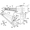
以下、本発明に係るプリンター装置1の好ましい実施の形態について、図1から図7を参照して説明する。なお、説明の便宜上、図1に示す矢印の方向をそれぞれ左右、前後および上下方向と定義する。図1に示すように、プリンター装置1は、ロール状に巻き取られて運搬されるシート状の印刷媒体2に対して、液体インクを噴射することで印刷を行う印刷装置であり、プリンター装置1の上部に設けられて印刷を行う印刷部10とプリンター装置1の下部に設けられた保持部50とから構成される。
Hereinafter, a preferred embodiment of a
印刷部10は、左収納部11、右収納部12、印刷ヘッド13、ガイドレール14、押え15およびプラテン16を主体に構成される。ガイドレール14は、印刷媒体2の左右幅よりも長く左右方向に延びて形成されており、その左右両端部は左収納部11および右収納部12に収納され、ガイドレール14の前側面には、印刷ヘッド13の前後方向ならびに上下方向の移動を規制するための凹凸が、左右方向に延びて形成されている。
The
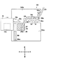
印刷ヘッド13は、その後側面で形成された凹凸が、ガイドレール14の前側面に形成された凹凸と摺動可能に係合することで、ガイドレール14に沿って左右方向に往復自在であり、印刷ヘッド13の内部には、複数のインクカートリッジ(図示せず)から送られてきた液体インクを、プラテン16上の印刷媒体2に向けて噴射可能となるように下方に向けて設置された複数のノズル(図示せず)が、印刷媒体2と対向して設置されている。また、印刷ヘッド13は、図3に示すように平面視において、その右側面に略三角形状で上下方向に所定幅を有した摺動突起13aが右方向に向けて立設しており、この摺動突起13aの後側面には、左側後方から右側前方に向けて傾斜した摺動斜面13bが形成されて、上下方向において、この摺動斜面13bと後述する当接円柱32とが当接するように構成されている。さらに、印刷ヘッド13は、ガイドレール14に沿って右側端部(待機位置)に移動したときに、印刷ヘッド13と後述するメンテナンス装置20のインク受容室35とが、上下に対向するように構成されている。なお、印刷時には、ノズルから噴射された印刷インクが、印刷ヘッド13の下面で開口した噴出開口13cを通過して、印刷媒体2に付着することで印刷が行われる。
The
左収納部11は、プリンター装置1の上方左端部に配設されており、ガイドレール14の左端部を覆って箱状に形成される。右収納部12は、プリンター装置1の上方右端部に配設されており、ガイドレール14の右端部を覆って箱状に形成されており、右収納部12の内部には、メンテナンス装置20が備えられている。なお、左収納部11および右収納部12の内部には、例えば、図示しないプリンター装置1を操作するための操作パネル、およびノズルから噴射されるインクを蓄えたインクカートリッジ等が設置されている。
The left storage unit 11 is disposed at the upper left end of the
プラテン16は、印刷媒体2の左右幅よりも長く左右方向に延びて、印刷ヘッド13の下方に設置されており、図1に示すように、その前後方向の両端部では印刷媒体2の供給および排出が容易となるように傾斜しているとともに、印刷ヘッド13と対向する部分においては、印刷ヘッド13の下面と平行に構成されている。押え15は、印刷媒体2の左右幅よりも長く左右方向に延びて、ガイドレール14の下方に設置されており、印刷ヘッド13の後方に設置されるとともに、押え15の下方先端部で印刷媒体2と当接する部分に、回転ローラ(図示せず)を有している。また、押え15は上下方向に揺動自在に構成されており、押え15が下方に揺動して、プラテン16上の印刷媒体2を回転ローラが上方から押圧することによって、印刷媒体2の搬送方向への移動を規制することができる。
The
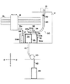
メンテナンス装置20は、図1および図2に示すように、洗浄液カートリッジ21、支持容器30、揺動部材33、インク受容室35、ワイパー38、排出ポンプ40および廃液タンク43を主体に構成される。洗浄液カートリッジ21は、残留インクと溶け合うことでインク受容室35内部に溜まった残留インクの濃度を下げる洗浄液を内部に有したカートリッジで、右収納部12の上面に載置されている。また、洗浄液カートリッジ21は、その前側面において、上下に延びるように設置された、例えば樹脂材料を用いて変形自在な管状に形成された洗浄液通路23の一端と連通しているとともに、制御バルブ22が洗浄液通路23の上端部近傍に設置されており、制御バルブ22によって、洗浄液カートリッジ21から洗浄液が自然流下するのを制御可能となっている。
As shown in FIGS. 1 and 2, the
支持容器30は、図1に示すように、右収納部12の内部に設置されており、図2および図3に示すように、例えば樹脂材料を用いて、上面が開口した箱状に形成された支持箱部30aと、例えば金属材料を用いて形成された、支持箱部30aの上方開口部の後方縁部に設置されて後方に延びた板状の支持台30bとから構成されている。ここで、支持容器30は、その上面開口部が印刷ヘッド13の下面と干渉しない上下位置となっており、また、支持台30bは、図3に示すように、右側前方で切り欠き部を有しており、その後方端部で後方縁部30cが形成されている。
As shown in FIG. 1, the
揺動部材33は、図3に示すように、平面視において例えば樹脂材料を用いて、左右方向に延びた板状に形成されており、揺動部材33の右側面には右方向に延びた棒状の戻り突起33aが形成されている。また、ばね33bの一端が戻り突起33aの右側先端部に取り付けられるとともに、ばね33bの他端は、後方縁部30cに取り付けられている。ここで、支持台30bの上面に揺動部材33を載置した状態で、支持台30bと揺動部材33の右側端部とが枢結ピン31によって枢結されて、揺動部材33は枢結ピン31を中心として、前後方向に揺動自在となっている。つまり、揺動部材33を後方に揺動させた後に揺動状態を保持する力を取り除くと、ばね33bの弾性力によって、図3に示す位置に戻る構成となっている。さらに、揺動部材33の左右中心付近には、揺動部材33の上面から円柱形状で上方に延びた当接円柱32が立設している。
As shown in FIG. 3, the
また、揺動部材33の上面には、例えば板状に形成された固定部材34の一端が固定されている。一方、固定部材34の他端部分では、例えば金属製で管状に形成されて、略くの字状に折曲した注入パイプ24の一端が、固定部材34によって保持されているとともに、この注入パイプ24の一端は、上述の洗浄液通路23の下端部と連通している。ここで、印刷ヘッド13が待機位置にいない場合において、注入パイプ24の他端の注入口24aは、図6に示すように、平面視においてインク受容室35の中心部付近に位置するように構成されている。なお、上下方向において、図2に示すように、注入パイプ24は、印刷ヘッド13の下面と干渉しないように、印刷ヘッド13の下面よりも下方に設置されている。
Further, one end of a fixing
インク受容室35は、例えば樹脂材料を用いて、図2に示すように、上面が開口して内部が中空の略直方体状に形成され、支持箱部30aの内部に設置されており、上下方向において、インク受容室35の上面開口部と支持箱部30aの上面開口部とは、略同一高さに構成されている。また、インク受容室35内部の中空部には、多孔質状の吸着部材36が挿入されているとともに、吸着部材36の上面には、インク受容室35の上方開口部を覆うように、例えば金属製で網状に形成された上枠37が、上方からインク受容室35に設置されて固定されている。なお、この上枠37は、吸着部材36が上方開口部から上方に突出しないように保持している。
As shown in FIG. 2, the
ワイパー38は、例えば樹脂材料を用いて、前後方向に延びた板状に形成されており、図2に示すように、上下方向において、印刷ヘッド13の下面と当接可能な位置に設置されている。また、ワイパー38はその下方において、支持箱部30aの内部に設置されているワイパー駆動部38aと連結しており、このワイパー駆動部38aによって、ワイパー38は図3に示すように前後方向に往復自在である。なお、後方側に移動したときに噴出開口13cとワイパー38の上方先端部とが当接可能となる。
The
排出ポンプ40は、稼動することによって液体を強制的に流入および排出させることができる装置で、プリンター装置1の内部に設置されており、図2に示すように、例えば樹脂材料を用いて管状に形成されて、一端がインク受容室35の底部で開口した開口部と連通した第1排出通路41の他端と排出ポンプ40の流入口が連通しており、一方で、例えば樹脂材料を用いて管状に形成されて、一端が廃液タンク43と連通した第2排出通路42の他端と排出ポンプ40の排出口が連通している。廃液タンク43は、内部に中空部を有したタンクで、その上端部で第2排出通路42の一端と連通しており、第2排出通路42を進行してきた液体を流入されて溜めておくことが可能である。
The
保持部50は、図1に示すように、土台51、支持体52、ガイド支持アーム53、第1ガイド部材54、シート供給部60、固定アーム70および第2ガイド部材71を主体に構成されている。なお、後側面も前側面と同様に構成され、前側面におけるシート供給部60と前後方向に関して対称な位置に、シート巻取り部(図示せず)が設置されており、保持部50の後側面についての説明は省略する。
As shown in FIG. 1, the holding
土台51は、略直方体状で印刷媒体2の左右幅よりも長く左右方向に延びて形成されており、その上部に設置された印刷部10を支持するように構成されている。支持体52は、略直方体状で前後方向に延びて形成され、土台51下方の左右両端部近傍において、その後端面が土台51に固定されている。固定アーム70は、板状で前後方向に延びて形成されており、支持体52とほぼ同じ左右位置の左右両端部近傍で、かつ支持体52の上方において、固定アーム70の後端部が土台51に固定されている。
The
第1ガイド部材54は、図1に示すように、例えば金属材料を用いて、その断面が円筒形で、印刷媒体2の左右幅よりも長く左右方向に延びて形成されており、その左右両端部がガイド支持アーム53の前端部によって回転自在に支持されている。ガイド支持アーム53は、その後端部が、支持体52によって回転自在に支持されている。このように構成することで、ガイド支持アーム53および第1ガイド部材54は、ガイド支持アーム53の後端部を中心として、上下方向に揺動可能となっている。
As shown in FIG. 1, the
シート供給部60は、左右方向に延びるシート供給軸61の周囲に、印刷される前の印刷媒体2が巻かれたもので、シート供給軸61の左右両端部が、支持体52によって回転自在に支持されている。なお、シート供給軸61の支持体52に支持されている部分において、シート供給軸61に回転駆動を与えること、およびシート供給軸61が自由に回転するのを防止するためのブレーキを掛けることが可能に構成されている。
The
シート巻取り部は、土台51の後側面に設置され、左右方向に延びるシート巻き取り軸(図示せず)の周囲に、印刷済みの印刷媒体2が巻かれたもので、シート巻き取り軸の左右両端部が支持体(図示せず)によって回転自在に支持されている。また、上記のシート供給部60と同様に、シート巻き取り軸の支持体に支持されている部分において、シート巻き取り軸に回転駆動を与えること、およびシート巻き取り軸が自由に回転するのを防止するためのブレーキを掛けることが可能に構成されている。
The sheet winding unit is installed on the rear side surface of the
第2ガイド部材71は、例えば金属材料を用いて、その断面が円筒形で、印刷媒体2の
左右幅よりも長く左右方向に延びて形成されるとともに、その外周部は滑らかな表面を有
している。また、第2ガイド部材71は、その左右両端部が固定アーム70によって挟持
されるとともに固定され、さらに、固定アーム70が土台51の前側面に設置されて、印
刷媒体2をプラテン16の前方端部の傾斜部に、スムーズに導くことが可能となっている
。
The
以上、ここまでは、プリンター装置1の構成について説明したが、以下において、印刷
ヘッド13およびメンテナンス装置20の動作を、図7に示すフローチャートを参照しな
がら説明する。
The configuration of the
まず、ステップS1において、図5に示すように、印刷ヘッド13はガイドレール14の右側端部の待機位置におり、このとき、当接円柱32が摺動斜面13bに当接するとともに、揺動部材33が注入パイプ24および固定部材34とともに、枢結ピン31を中心として後方に揺動し、注入パイプ24は、インク受容室35の上面から離れた位置に退避しており、噴出開口13cとインク受容室35の上面開口部とは、平面視において略重なっている。また、戻り突起33aは枢結ピン31を中心として前方に揺動し、ばね33bは前方側に引っ張られて弾性力を蓄えた状態となっており、ワイパー38は、実線で示すように前方側に位置しており、この位置では、印刷ヘッド13がガイドレール14に沿って左方向に移動しても噴出開口13cと当接しない。
First, in step S1, as shown in FIG. 5, the
次に、ステップS2において、図5に示す状態で、各ノズルのノズル先端部分で滞留した残留インクを、インク受容室35に向けて噴射して排出する。このとき、上述のとおり噴出開口13cとインク受容室35の上面開口部とは略重なっているとともに、注入パイプ24がインク受容室35の上面部から退避しているので、噴射された残留インクをインク受容室35で確実に受容可能である。また、この排出された残留インクは、吸着部材36に浸透していき、その後インク受容室35の下方へと流下し、インク受容室35の底部に堆積する。
Next, in step S2, in the state shown in FIG. 5, the residual ink staying at the nozzle tip of each nozzle is ejected toward the
次に、ステップS3に進み、図5に示すように、ワイパー38がワイパー駆動部38aによって、二点破線で示す38bの位置に移動する。このとき、38bの位置に移動することで、印刷ヘッド13がガイドレール14に沿って左方向に移動するときに、噴出開口13cにワイパー38の先端部が当接可能となる。
Next, it progresses to step S3 and as shown in FIG. 5, the
次に、ステップS4において、印刷ヘッド13は、待機位置からガイドレール14に沿って左方向に移動して印刷が開始されるが、このとき、図5に示すように、ワイパー38が破線で示す38bの位置にあり、噴出開口13cにワイパー38の先端が当接しながら左方向に移動することで、噴出開口13c付近に付着した残留インクを、ワイパー38によって拭き取ることができ、よって、噴出開口13cで噴射した印刷インクと残留インクとが混ざり合うことがないので、印刷時の印刷精度を向上させることが可能である。
Next, in step S4, the
また、ステップS4において、印刷ヘッド13が待機位置からガイドレール14に沿って左方向に移動するとき、ばね33bの弾性力により前方に押圧されて摺動斜面13bに当接している当接円柱32が、摺動斜面13bに沿って当接状態を保持しながら前方に移動することで、揺動部材33が注入パイプ24および固定部材34とともに、枢結ピン31を中心として前方に揺動する。その後、摺動斜面13bと当接円柱32とが当接しない位置まで印刷ヘッド13が左方向に移動すると、注入口24aがインク受容室35の上面開口部の中心付近に位置するように構成されている(図3を参照)。また、ワイパー38は、その上方を印刷ヘッド13が通過することで噴出開口13cの残留インクを拭き取った後、ワイパー駆動部38aによって、再び実線で示す38の位置に戻る。なお、プラテン16の上方に移動した印刷ヘッド13は、プラテン16の上方を左右方向に往復移動しながら、ノズルから印刷媒体2に向けて印刷インクを噴射するとともに、印刷媒体2を搬送方向に搬送して所望の印刷を行う。
In step S4, when the
次に、ステップS5に進み、印刷ヘッド13が印刷媒体2に印刷を行っている間、メンテナンス装置20では、図6に示す状態において、まず、制御バルブ22が一定時間開放されることで、洗浄液が洗浄液カートリッジ21から洗浄液通路23、注入パイプ24へと自然流下した後、注入口24aからインク受容室35の上面開口部の中心付近に注入される。このとき、制御バルブ22を開放するとともに、排出ポンプ40も一定時間駆動させることで、インク受容室35の底部に堆積した残留インクおよび洗浄液が、第1排出通路41から排出ポンプ40へと強制的に流入した後、排出ポンプ40から第2排出通路42を介して廃液タンク43へと強制的に排出される。なお、注入口24aからの洗浄液の注入、および排出ポンプ40の駆動は、次のステップS6に進む前に終了する。
Next, in step S5, while the
次に、ステップS6において、一定時間印刷媒体2に印刷を行った後、印刷ヘッド13は、右側端部の待機位置に戻ってくるが、このとき、右側端部近傍で図3に示す状態から図4の状態に移行した後、さらに、図4に示す状態から図5の状態(待機位置)に移行する。この移行過程を順に説明すると、まず、図3に示すように、印刷ヘッド13が、支持容器30の左方向から右方向へと、待機位置に向けて進行してくる。その後、図3に示す状態から印刷ヘッド13がさらに右方向に進むことで、摺動斜面13bと当接円柱32とが当接し、その状態でさらに、印刷ヘッド13が右方向に移動することで、図4に示すように、当接円柱32が摺動斜面13bに沿って後方へ移動するとともに、揺動部材33、注入パイプ24および固定部材34が、枢結ピン31を中心として後方に揺動する。なお、このとき、戻り突起33aは、枢結ピン31を中心として前方に揺動して、ばね33bを伸ばす。その後、印刷ヘッド13が、さらに右方向に移動することで、図5に示す待機位置に戻り、噴出開口13cとインク受容室35の上面開口部とは、平面視において略重なっている。この状態の説明は、上述した通りなので省略する。
Next, in step S6, after printing on the
次に、ステップS7に進み、印刷すべき領域が残っていると判断した場合には、ステップS2に戻り、印刷媒体2への印刷が全て完了したと判断されるまでステップS2からステップS6を繰り返す。一方、印刷媒体2への印刷が全て完了したと判断した場合にはこのフローチャートは終了する。
Next, the process proceeds to step S7, and if it is determined that there is an area to be printed, the process returns to step S2, and steps S2 to S6 are repeated until it is determined that printing on the
ここで、本発明に係るプリンター装置1の効果について簡潔にまとめると、まず第1に、インク受容室35に洗浄液を注入することで、インク受容室35内で受容した残留インクの濃度を下げることができ、よって、第1排出通路41および第2排出通路42の内部でインクが固化せず、確実にインク受容室35内の残留インクを外部に排出可能となる。さらに、インク受容室35内で受容した残留インクの濃度を下げることができるので、第1排出通路41および第2排出通路42を、小さな内径を有した部材で構成しても固化することがなく、プリンター装置1の製作コストを削減することが可能となる。
Here, the effects of the
第2に、注入パイプ24を用いてインク受容室35の中央部に洗浄液を注入することで、インク受容室35の内部に均一に洗浄液を浸透させて、インク受容室35の内部の残留インク全体の濃度を下げることができるので、残留インクがインク受容室35内部で固化することがなく、よって、インク受容室35の清掃回数を減らすことができ、プリンター装置1の作業効率を向上させることが可能となる。
Secondly, the cleaning liquid is injected into the central portion of the
第3に、印刷ヘッド13が待機位置にあるときに、摺動突起13aと当接円柱32とが当接して、揺動部材33が揺動することで、注入パイプ24がインク受容室35の上面から退避するので、例えばセンサー等を用いることなく、安価かつ簡易な方法で注入パイプ24を退避させることが可能となるので、プリンター装置1の製作コストを削減することが可能となる。さらに、この揺動した揺動部材33を、ばね33bによって元の位置に戻す構成とすることで、例えばモータ等を用いることなく、安価かつ簡易な方法で揺動部材33を元の位置に戻すことが可能となるので、プリンター装置1の製作コストを削減することが可能となる。
Thirdly, when the
上述の実施形態において、ステップS5で、制御バルブ22の開放時間および排出ポンプ40の駆動時間は、任意に設定可能であるが、吸着部材36に均一に洗浄液が浸透するように制御バルブ22の開放時間を設定するとともに、インク受容室35の底部に溜まった残留インクおよび洗浄液を、第1排出通路41および第2排出通路42の内部に残留せず、すべて廃液タンク43に排出されるように排出ポンプ40の駆動時間を設定することが好ましい。
In the above-described embodiment, the opening time of the control valve 22 and the driving time of the
上述の実施形態において、摺動突起13aと当接円柱32とが当接して、揺動部材33が揺動することで、注入パイプ24がインク受容室35の上面から退避する構成となっているが、注入パイプ24をインク受容室35の上面から退避させる手段は、上述の実施形態に示すものに限られない。
In the above-described embodiment, the sliding
上述の実施形態において、印刷ヘッド13が一定時間印刷を行った後、待機位置へ戻ってくるときには、ワイパー38を噴出開口13cに当接させない構成となっているが、この場合にも、印刷ヘッド13が待機位置からプラテン16上方へ移動するときと同様に、ワイパー38を噴出開口13cに当接させるように構成しても良い。
In the above-described embodiment, when the
上述の実施形態において、印刷ヘッド13の下面と注入パイプ24とは、上下方向において干渉しない構成となっているが、一方で、印刷ヘッド13の下面と注入パイプ24とが干渉する場合であっても、退避手段によって、注入パイプ24が印刷ヘッド13の通過する領域の外部へ完全に退避する構成とすることで、注入パイプ24と印刷ヘッド13との干渉を防止できる。よって、この場合でも、本発明に係る注入パイプ24をインク受容室35の上面に設けることが可能である。
In the above-described embodiment, the lower surface of the
1 プリンター装置
2 印刷媒体
13 印刷ヘッド
13a 摺動突起(退避手段)
16 プラテン(媒体支持部材)
20 メンテナンス装置
24 注入パイプ(液体注入部)
32 当接円柱(退避手段)
35 インク受容室
DESCRIPTION OF
16 Platen (medium support member)
20
32 Contact cylinder (retraction means)
35 Ink receiving chamber
Claims (2)
前記媒体支持部材と上下に対向して下方に向けてインクを噴射するノズルを備えて前記媒体支持部材の上方を左右方向に往復移動自在な印刷ヘッドと、
前記印刷ヘッドが一方の往復移動端部に移動した位置において前記印刷ヘッドの下方に対向して設置されて、前記印刷ヘッドが前記一方の往復移動端部に移動した位置において前記ノズルから噴射される前記ノズル内部に残留した残留インクを受容するメンテナンス装置とを有し、
前記印刷ヘッドを往復移動させるとともに前記ノズルから印刷インクを印刷媒体に噴射して所望の印刷を行うプリンター装置において、
前記メンテナンス装置が、
上方に向けて開口して前記ノズルから噴射される残留インクを受容するインク受容室と、
前記印刷ヘッドが前記インク受容室上方から離れているときに、前記インク受容室上方に位置して前記インク受容室に液体を注入する液体注入部と、
前記インク受容室から排出された残留インクおよび液体を貯留する廃液貯留部と、
前記インク受容室と前記廃液貯留部とを繋いで設けられた排出通路と、
前記インク受容室内の残留インクおよび液体を前記排出通路を介して前記廃液貯留部に排出させる排出ポンプとを有して構成され、
前記排出ポンプを駆動させることにより、前記インク受容室内の残留インクおよび液体を前記排出通路内に残留させないように前記廃液貯留部に排出させることが可能に構成されており、
前記液体注入部は、前記インク受容室上方の注入位置と前記インク受容室上方から離れた退避位置との間で移動可能に設けられるとともに、常には前記注入位置に保持されており、
前記印刷ヘッドが前記インク受容室上方に移動するときに、前記印刷ヘッドが前記液体注入部に当接して前記印刷ヘッドが前記液体注入部を押すことで、前記液体注入部が前記注入位置から前記退避位置に移動されるように構成されたことを特徴とするプリンター装置。 A medium support member for placing and supporting a print medium having a predetermined width in the left-right direction;
A print head that includes a nozzle that is vertically opposed to the medium support member and ejects ink downward, and is capable of reciprocating in the left-right direction above the medium support member;
The print head is disposed opposite to the print head at a position where the print head moves to one reciprocating end, and is ejected from the nozzle at a position where the print head moves to the one reciprocating end. A maintenance device for receiving residual ink remaining in the nozzle,
In a printer device that performs desired printing by reciprocating the print head and ejecting printing ink from the nozzles onto a print medium,
The maintenance device is
An ink receiving chamber that opens upward and receives residual ink ejected from the nozzle;
When said print head is away from the ink receiving chamber upward, a fluid injecting section for injecting a liquid into said ink receiving chamber located in the ink-receiving chamber upward,
A waste liquid storage section for storing residual ink and liquid discharged from the ink receiving chamber;
A discharge passage provided by connecting the ink receiving chamber and the waste liquid reservoir;
A discharge pump configured to discharge residual ink and liquid in the ink receiving chamber to the waste liquid storage section through the discharge passage;
By driving the discharge pump, it is configured to be able to discharge the residual ink and liquid in the ink receiving chamber to the waste liquid storage unit so as not to remain in the discharge passage .
The liquid injection part is provided so as to be movable between an injection position above the ink receiving chamber and a retracted position away from the upper side of the ink receiving chamber, and is always held at the injection position.
When the print head moves above the ink receiving chamber, the print head abuts on the liquid injection portion and the print head pushes the liquid injection portion, so that the liquid injection portion is moved from the injection position to the liquid injection portion. A printer apparatus configured to be moved to a retracted position .
前記印刷ヘッドは、前記一方側にヘッド側当接部を備え、
前記揺動部材は、前記ヘッド側当接部と左右方向に当接する揺動部材側当接部を備えており、
前記印刷ヘッドが前記インク受容室上方に移動するときに、前記ヘッド側当接部が前記揺動部材側当接部に当接して前記注入管部が前記注入位置から前記退避位置に揺動されるように構成されたことを特徴とする請求項1に記載のプリンター装置。 The liquid injection part is formed in a tubular shape, and an injection tube part that injects liquid into the ink receiving chamber by dropping liquid from the tip part, and the injection pipe part is attached to connect the injection tube part to the injection position and the injection part. A swing member provided so as to be swingable between the retracted position and
The print head includes a head side contact portion on the one side,
The swing member includes a swing member side contact portion that contacts the head side contact portion in the left-right direction,
When the print head moves above the ink receiving chamber, the head side contact portion contacts the swing member side contact portion, and the injection tube portion swings from the injection position to the retracted position. The printer device according to claim 1, wherein the printer device is configured as described above.
Priority Applications (8)
| Application Number | Priority Date | Filing Date | Title |
|---|---|---|---|
| JP2007111465A JP5150129B2 (en) | 2007-04-20 | 2007-04-20 | Printer device |
| CN2008100052208A CN101289021B (en) | 2007-04-20 | 2008-01-31 | Printer device |
| KR1020080032518A KR100991161B1 (en) | 2007-04-20 | 2008-04-08 | Printer apparatus |
| US12/100,857 US8109601B2 (en) | 2007-04-20 | 2008-04-10 | Printer |
| ES08290374T ES2336281T3 (en) | 2007-04-20 | 2008-04-16 | PRINTER. |
| DE602008000254T DE602008000254D1 (en) | 2007-04-20 | 2008-04-16 | printer |
| EP08290374A EP2000310B1 (en) | 2007-04-20 | 2008-04-16 | Printer |
| AT08290374T ATE447487T1 (en) | 2007-04-20 | 2008-04-16 | PRINTER |
Applications Claiming Priority (1)
| Application Number | Priority Date | Filing Date | Title |
|---|---|---|---|
| JP2007111465A JP5150129B2 (en) | 2007-04-20 | 2007-04-20 | Printer device |
Related Child Applications (1)
| Application Number | Title | Priority Date | Filing Date |
|---|---|---|---|
| JP2012260414A Division JP5347208B2 (en) | 2012-11-29 | 2012-11-29 | Printer device |
Publications (3)
| Publication Number | Publication Date |
|---|---|
| JP2008265148A JP2008265148A (en) | 2008-11-06 |
| JP2008265148A5 JP2008265148A5 (en) | 2010-05-13 |
| JP5150129B2 true JP5150129B2 (en) | 2013-02-20 |
Family
ID=39789472
Family Applications (1)
| Application Number | Title | Priority Date | Filing Date |
|---|---|---|---|
| JP2007111465A Active JP5150129B2 (en) | 2007-04-20 | 2007-04-20 | Printer device |
Country Status (8)
| Country | Link |
|---|---|
| US (1) | US8109601B2 (en) |
| EP (1) | EP2000310B1 (en) |
| JP (1) | JP5150129B2 (en) |
| KR (1) | KR100991161B1 (en) |
| CN (1) | CN101289021B (en) |
| AT (1) | ATE447487T1 (en) |
| DE (1) | DE602008000254D1 (en) |
| ES (1) | ES2336281T3 (en) |
Families Citing this family (10)
| Publication number | Priority date | Publication date | Assignee | Title |
|---|---|---|---|---|
| EP2316653A4 (en) * | 2009-01-13 | 2013-04-03 | Mimaki Eng Kk | Bulk ink supply system |
| JPWO2010087012A1 (en) * | 2009-01-30 | 2012-07-26 | 株式会社ミマキエンジニアリング | Inkjet printer |
| JP2011110853A (en) * | 2009-11-27 | 2011-06-09 | Mimaki Engineering Co Ltd | Liquid circulating system |
| JP2011110851A (en) * | 2009-11-27 | 2011-06-09 | Mimaki Engineering Co Ltd | Liquid circulating system |
| JP5831678B2 (en) * | 2011-02-28 | 2015-12-09 | セイコーエプソン株式会社 | Liquid ejector |
| CN107948645B (en) | 2011-07-15 | 2021-12-24 | Ge视频压缩有限责任公司 | Decoder and method, encoder and method, and storage medium |
| JP5778531B2 (en) * | 2011-09-09 | 2015-09-16 | 株式会社ミマキエンジニアリング | Inkjet printer, ink recovery member, and ink recovery method |
| US9517882B1 (en) * | 2016-05-25 | 2016-12-13 | Xerox Corporation | Apparatus for collecting waste material in a large-scale ink-jet printer |
| JP7127433B2 (en) | 2018-08-30 | 2022-08-30 | セイコーエプソン株式会社 | LIQUID EJECTING DEVICE, MAINTENANCE METHOD OF LIQUID EJECTING DEVICE |
| JP2022055503A (en) * | 2020-09-29 | 2022-04-08 | セイコーエプソン株式会社 | Printing device |
Family Cites Families (19)
| Publication number | Priority date | Publication date | Assignee | Title |
|---|---|---|---|---|
| JP2962964B2 (en) * | 1992-06-26 | 1999-10-12 | キヤノン株式会社 | Liquid ejection device and printing method using the same |
| US5500659A (en) * | 1993-11-15 | 1996-03-19 | Xerox Corporation | Method and apparatus for cleaning a printhead maintenance station of an ink jet printer |
| JP3145896B2 (en) * | 1995-04-07 | 2001-03-12 | キヤノン株式会社 | Liquid ejecting apparatus and information processing system |
| US5742303A (en) * | 1995-05-24 | 1998-04-21 | Hewlett-Packard Company | Trap door spittoon for inkjet aerosol mist control |
| JP3111024B2 (en) * | 1995-07-19 | 2000-11-20 | キヤノン株式会社 | Apparatus and method for manufacturing color filter, method for manufacturing display apparatus, and method for manufacturing apparatus provided with display apparatus |
| US6460967B1 (en) * | 1998-03-24 | 2002-10-08 | Konica Corporation | Liquid jetting apparatus |
| US5997127A (en) | 1998-09-24 | 1999-12-07 | Eastman Kodak Company | Adjustable vane used in cleaning orifices in inkjet printing apparatus |
| JP2002019132A (en) | 2000-07-07 | 2002-01-23 | Mimaki Engineering Co Ltd | Mechanism and method for cleaning ink jet head of plotter |
| JP3992215B2 (en) * | 2000-08-11 | 2007-10-17 | キヤノンファインテック株式会社 | Ink jet recording apparatus and recovery system cleaning method thereof |
| JP2002079692A (en) | 2000-09-04 | 2002-03-19 | Funai Electric Co Ltd | Maintenance device for ink jet printer |
| JP3833085B2 (en) * | 2001-08-10 | 2006-10-11 | シャープ株式会社 | Tube processing method for ink jet recording apparatus |
| KR100426087B1 (en) * | 2001-10-12 | 2004-04-06 | 삼성전자주식회사 | Printhead cleaning apparatus and ink jet printer having the same |
| JP2004034655A (en) * | 2002-07-08 | 2004-02-05 | Seiko Epson Corp | Inkjet recorder |
| JP4385599B2 (en) * | 2002-12-20 | 2009-12-16 | セイコーエプソン株式会社 | Maintenance method for droplet discharge head, cleaning device for maintenance cap, droplet discharge device including the same, and method for manufacturing electro-optical device |
| JP2004314604A (en) * | 2003-03-31 | 2004-11-11 | Seiko Epson Corp | Liquid injection device having volume pump with built-in sliding rotor |
| JP2006043963A (en) | 2004-08-02 | 2006-02-16 | Sharp Corp | Cleaning unit and cleaning method for liquid applicator |
| KR100694121B1 (en) | 2005-06-02 | 2007-03-12 | 삼성전자주식회사 | Inkjet image forming apparatus and nozzle cleaning method thereof |
| JP4769499B2 (en) * | 2005-07-08 | 2011-09-07 | 富士フイルム株式会社 | Ink cartridge, ink jet recording apparatus, and waste ink cartridge |
| US7530664B2 (en) * | 2005-09-29 | 2009-05-12 | Seiko Epson Corporation | Maintenance device for liquid-ejecting apparatus and liquid-ejecting apparatus |
-
2007
- 2007-04-20 JP JP2007111465A patent/JP5150129B2/en active Active
-
2008
- 2008-01-31 CN CN2008100052208A patent/CN101289021B/en active Active
- 2008-04-08 KR KR1020080032518A patent/KR100991161B1/en not_active IP Right Cessation
- 2008-04-10 US US12/100,857 patent/US8109601B2/en not_active Expired - Fee Related
- 2008-04-16 DE DE602008000254T patent/DE602008000254D1/en active Active
- 2008-04-16 AT AT08290374T patent/ATE447487T1/en not_active IP Right Cessation
- 2008-04-16 ES ES08290374T patent/ES2336281T3/en active Active
- 2008-04-16 EP EP08290374A patent/EP2000310B1/en not_active Not-in-force
Also Published As
| Publication number | Publication date |
|---|---|
| CN101289021A (en) | 2008-10-22 |
| US8109601B2 (en) | 2012-02-07 |
| KR20080094567A (en) | 2008-10-23 |
| CN101289021B (en) | 2010-12-08 |
| US20080259117A1 (en) | 2008-10-23 |
| ATE447487T1 (en) | 2009-11-15 |
| JP2008265148A (en) | 2008-11-06 |
| EP2000310B1 (en) | 2009-11-04 |
| KR100991161B1 (en) | 2010-11-02 |
| DE602008000254D1 (en) | 2009-12-17 |
| ES2336281T3 (en) | 2010-04-09 |
| EP2000310A1 (en) | 2008-12-10 |
Similar Documents
| Publication | Publication Date | Title |
|---|---|---|
| JP5150129B2 (en) | Printer device | |
| JP3233175B2 (en) | Ink jet recording device | |
| JP5347208B2 (en) | Printer device | |
| WO2014069494A1 (en) | Inkjet printing device | |
| JP2010228214A (en) | Liquid ejecting apparatus and maintenance method thereof | |
| US10457053B2 (en) | Ink jet printer | |
| JP4635795B2 (en) | Inkjet recording device | |
| JP2015058673A (en) | Liquid injection apparatus | |
| JP4640069B2 (en) | Inkjet recording device | |
| JP6922611B2 (en) | Inkjet recording device | |
| JP4844413B2 (en) | Fluid ejection device | |
| JP2007223303A (en) | Liquid jetting device | |
| JP6700583B2 (en) | Liquid ejector | |
| JP4508121B2 (en) | Liquid ejector | |
| JP4946550B2 (en) | Wiping device, and maintenance unit and fluid ejection device including the wiping device | |
| JP4848807B2 (en) | Liquid ejector | |
| JP2010274599A (en) | Maintenance apparatus and liquid jetting apparatus | |
| JP2017127988A (en) | Liquid jet device | |
| JP3296431B2 (en) | Ink jet recording device | |
| JP4738191B2 (en) | Inkjet printer | |
| JP4501395B2 (en) | Liquid ejector | |
| JP2019142023A (en) | Wiping device, head maintenance device, and liquid discharging device | |
| JP2020116757A (en) | Wiping device, head maintenance device and device for discharging liquid | |
| JP2005335126A (en) | Liquid ejector | |
| JP2012086368A (en) | Wiping method, wiping control device and liquid injection device |
Legal Events
| Date | Code | Title | Description |
|---|---|---|---|
| A521 | Request for written amendment filed |
Free format text: JAPANESE INTERMEDIATE CODE: A523 Effective date: 20100329 |
|
| A621 | Written request for application examination |
Free format text: JAPANESE INTERMEDIATE CODE: A621 Effective date: 20100329 |
|
| A977 | Report on retrieval |
Free format text: JAPANESE INTERMEDIATE CODE: A971007 Effective date: 20111214 |
|
| A131 | Notification of reasons for refusal |
Free format text: JAPANESE INTERMEDIATE CODE: A131 Effective date: 20111216 |
|
| A521 | Request for written amendment filed |
Free format text: JAPANESE INTERMEDIATE CODE: A523 Effective date: 20120206 |
|
| A131 | Notification of reasons for refusal |
Free format text: JAPANESE INTERMEDIATE CODE: A131 Effective date: 20120309 |
|
| A521 | Request for written amendment filed |
Free format text: JAPANESE INTERMEDIATE CODE: A523 Effective date: 20120412 |
|
| TRDD | Decision of grant or rejection written | ||
| A01 | Written decision to grant a patent or to grant a registration (utility model) |
Free format text: JAPANESE INTERMEDIATE CODE: A01 Effective date: 20121102 |
|
| A61 | First payment of annual fees (during grant procedure) |
Free format text: JAPANESE INTERMEDIATE CODE: A61 Effective date: 20121203 |
|
| R150 | Certificate of patent or registration of utility model |
Ref document number: 5150129 Country of ref document: JP Free format text: JAPANESE INTERMEDIATE CODE: R150 Free format text: JAPANESE INTERMEDIATE CODE: R150 |
|
| FPAY | Renewal fee payment (event date is renewal date of database) |
Free format text: PAYMENT UNTIL: 20151207 Year of fee payment: 3 |
|
| R250 | Receipt of annual fees |
Free format text: JAPANESE INTERMEDIATE CODE: R250 |
|
| R250 | Receipt of annual fees |
Free format text: JAPANESE INTERMEDIATE CODE: R250 |
|
| R250 | Receipt of annual fees |
Free format text: JAPANESE INTERMEDIATE CODE: R250 |
|
| R250 | Receipt of annual fees |
Free format text: JAPANESE INTERMEDIATE CODE: R250 |
|
| R250 | Receipt of annual fees |
Free format text: JAPANESE INTERMEDIATE CODE: R250 |
|
| R250 | Receipt of annual fees |
Free format text: JAPANESE INTERMEDIATE CODE: R250 |
|
| R250 | Receipt of annual fees |
Free format text: JAPANESE INTERMEDIATE CODE: R250 |
|
| R250 | Receipt of annual fees |
Free format text: JAPANESE INTERMEDIATE CODE: R250 |
|
| R250 | Receipt of annual fees |
Free format text: JAPANESE INTERMEDIATE CODE: R250 |