EP2505315A2 - Elektrisches Werkzeuggerät mit einer Elektronikkühlung - Google Patents
Elektrisches Werkzeuggerät mit einer Elektronikkühlung Download PDFInfo
- Publication number
- EP2505315A2 EP2505315A2 EP20120154408 EP12154408A EP2505315A2 EP 2505315 A2 EP2505315 A2 EP 2505315A2 EP 20120154408 EP20120154408 EP 20120154408 EP 12154408 A EP12154408 A EP 12154408A EP 2505315 A2 EP2505315 A2 EP 2505315A2
- Authority
- EP
- European Patent Office
- Prior art keywords
- cooling
- motor
- motor housing
- cooled
- electronic component
- Prior art date
- Legal status (The legal status is an assumption and is not a legal conclusion. Google has not performed a legal analysis and makes no representation as to the accuracy of the status listed.)
- Granted
Links
Images



Classifications
-
- B—PERFORMING OPERATIONS; TRANSPORTING
- B23—MACHINE TOOLS; METAL-WORKING NOT OTHERWISE PROVIDED FOR
- B23Q—DETAILS, COMPONENTS, OR ACCESSORIES FOR MACHINE TOOLS, e.g. ARRANGEMENTS FOR COPYING OR CONTROLLING; MACHINE TOOLS IN GENERAL CHARACTERISED BY THE CONSTRUCTION OF PARTICULAR DETAILS OR COMPONENTS; COMBINATIONS OR ASSOCIATIONS OF METAL-WORKING MACHINES, NOT DIRECTED TO A PARTICULAR RESULT
- B23Q11/00—Accessories fitted to machine tools for keeping tools or parts of the machine in good working condition or for cooling work; Safety devices specially combined with or arranged in, or specially adapted for use in connection with, machine tools
- B23Q11/12—Arrangements for cooling or lubricating parts of the machine
- B23Q11/126—Arrangements for cooling or lubricating parts of the machine for cooling only
- B23Q11/127—Arrangements for cooling or lubricating parts of the machine for cooling only for cooling motors or spindles
-
- B—PERFORMING OPERATIONS; TRANSPORTING
- B25—HAND TOOLS; PORTABLE POWER-DRIVEN TOOLS; MANIPULATORS
- B25F—COMBINATION OR MULTI-PURPOSE TOOLS NOT OTHERWISE PROVIDED FOR; DETAILS OR COMPONENTS OF PORTABLE POWER-DRIVEN TOOLS NOT PARTICULARLY RELATED TO THE OPERATIONS PERFORMED AND NOT OTHERWISE PROVIDED FOR
- B25F5/00—Details or components of portable power-driven tools not particularly related to the operations performed and not otherwise provided for
- B25F5/008—Cooling means
Definitions
- the present invention relates to an electric power tool according to the preamble of claim 1.
- wall saws and drills are summarized that have equipped with cutting segments diamond tools in the form of saw blades or drill bits; In addition to diamond tools and tools with similar acting cutting materials can be used.
- Wall saws are used for cutting through reinforced and non-reinforced walls, ceilings and floors made of concrete or similar substrates and are used in civil engineering, renovation and renovation. In the case of demolition or conversion work, it may be necessary to sever existing concrete walls, remove them or cut out areas of the concrete walls.
- Drilling rigs are used to drill holes in concrete, brick, masonry and other mineral substrates.
- An electric power tool includes a tool that is rotatable about an axis of rotation, an engine assembly having at least one motor that rotates the tool about the axis of rotation, a motor housing with at least one receiving space for the engine, a cooling element for cooling the at least one motor and a Electronic assembly with at least one electronic component to be cooled.
- An electric wall saw known as the TS-5 includes a motor housing for the motor assembly and an electronics housing for the electronics assembly.
- the electronics components of the electronic assembly to be cooled are mounted on a cooling element designed as a cooling plate.
- the cooling plate comprises a cooling structure with one or more cooling channels through which a cooling medium flows for cooling.
- the motor is cooled by a cooling channel that surrounds the motor in a spiral shape.
- the cooling medium flows through an inlet port into the electronics housing, flows through the cooling plate of the electronics cooling, then the spiral cooling channel of the engine cooling and from there via a cooling hole in the saw arm.
- the cooling medium flows through outlet openings in the saw blade flange and cools the saw blade during machining.
- the electronics assembly is not housed in the saw head, but in a separate supply unit.
- the electronic components of the electronics module are mounted on a cooling plate, which has a cooling structure with cooling channel, as in the case of the TS-5.
- the saw head is connected via a line to the supply unit.
- the cooling circuit includes electronic cooling, engine cooling and saw blade cooling.
- the disadvantage is that a cooling plate with cooling channels is required to cool the electronic assembly.
- the cooling medium flows through the electronics module, which increases the risk of a short circuit due to moisture.
- the object of the present invention is to simplify the cooling of the electronic assembly and to reduce the number of components required for electronic cooling. In addition, the risk of a short circuit in the cooling of the electronics assembly is to be reduced.
- the cooling of the at least one electronic component of the electronic assembly to be cooled takes place via the motor housing.
- the integration of cooling surfaces and / or cooling holes in the motor housing reduces the number of sealing points. This reduces the risk of the electronic components coming into contact with the cooling medium.
- At least one cooling surface for an electronic component to be cooled is preferably provided on the motor housing. It is advantageous that the size of the cooling surface can be adapted to the electronic component to be cooled. So can the available space of the motor housing best used and the tool device are made smaller and lighter.
- At least one cooling hole for an electronic component to be cooled is provided in the motor housing.
- the cooling bore has the advantage that cylindrical electronic components, such as braking resistors, can be cooled via the surrounding housing surfaces of the motor housing. The space of the motor housing is utilized and the tool device can be made smaller and lighter.
- At least one cooling surface on the motor housing and / or at least one cooling bore in the motor housing are provided for each electronic component of the electronic assembly to be cooled. Since only the cooling element is flowed through by the cooling medium, the number of sealing points is reduced. This reduction reduces the risk of the electronics components coming into contact with the cooling medium and the cooling medium causing damage to the electronic components.
- Fig. 1 shows a designed as an electric wall saw 1 inventive electric power tool in a three-dimensional representation.
- the wall saw 1 consists of a saw unit 2 and a fastening device 3 for fastening the saw unit 2 to a substrate 4 to be processed .
- the saw unit 2 comprises a saw head 5, a saw arm 6, on which a saw blade 7 is arranged, and a guide carriage 8. To protect the operator, the saw blade 7 may be surrounded by a blade guard, which is arranged on the saw arm 6 by means of a blade guard 9 .
- the saw blade 7 is arranged on a saw blade flange 10 and is driven in the sawing operation about an axis of rotation 11 .
- the saw arm 6 is formed pivotable about a pivot axis 12 ; Alternatively, the saw arm is adjustable by means of a linear drive or other drive means.
- the saw unit 2 is fastened with the fastening device 3 consisting of a guide rail 13 and rail feet 14 on the substrate 4 to be processed.
- the saw unit 2 is arranged longitudinally displaceably over the guide carriage 8 on the guide rail 13 in a feed direction 15 and in a direction opposite to the feed direction 15.
- the saw head 5 comprises a motor housing 16, a motor assembly 17, an electronics assembly 18 and a housing cover 19.
- the motor assembly 17 includes a first motor 20 for the rotational movement of the saw blade 7 about the rotation axis 11, a second motor 21 for the pivotal movement of the saw arm 6 to the pivot axis 12 and a third motor 22 for the advancing movement of the guide carriage 8 along the feed direction 15.
- the electronic assembly 18 includes all electronic components of the power electronics. These include, inter alia, frequency converter for the motors 20, 21, 22 and a braking resistor for the destruction of braking energy when braking the saw blade. 7
- the cooling of the saw unit 2 via a cooling medium, which is designed for example as a cooling liquid, cooling gas or compressed air.
- the cooling medium is stored in a separate container.
- the container is connected via a supply line to an inlet port 23 , which in turn is connected to the motor housing 16.
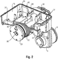
- Fig. 2 shows a part of the motor housing 16, in which the first motor 20 is installed for the rotational movement of the saw blade 7 about the axis of rotation 11.
- the motor housing 16 includes a first accommodating space 30 for the first motor 20, a second accommodating space 31 for the second motor 21, and a third accommodating space 32 (in FIG Fig. 3 ) for the third motor 22.
- the cooling medium flows out of the container via the supply line into the motor housing 16.
- a valve device 34 With the aid of a valve device 34 , the supply of the cooling medium to the cooling channel 33 is regulated.
- the spiral-shaped cooling channel 33 it is possible, for example, to use a meander-shaped cooling channel.
- a plurality of cooling channels may be provided, which are connected in series or in parallel.
- the motor housing 16 three cooling surfaces 35, 36, 37 and a cooling bore 38 are provided.
- a frequency converter for the first motor 20 is positioned and connected with the best possible heat transfer to the motor housing 16.
- the first cooling surface 35 is arranged very close to the cooling channel 33 and is therefore preferred in terms of the cooling effect with respect to the second and third cooling surfaces 36, 37.
- the electronic components to be cooled are distributed on the cooling surfaces so that the electronic components with the strongest heat development are arranged as close as possible to the cooling channel 33. The lower the heat development, the farther away from the cooling channel 33, the electronic component can be arranged.
- a heat-conducting pad or a heat-conducting paste can be provided between the electronic component and the cooling surface 35, 36, 37 of the motor housing 16. Since the cooling of the electronic components of the electronic assembly 18 takes place exclusively via the motor housing 16, a sufficient heat transfer must be ensured.
- Befest Trentsdome 39 are provided in the motor housing 16, which are connected via reinforcing ribs 40 .
- Fig. 3 shows a cross section through the motor housing 16 with the first receiving space 30 for the first motor 20, the second receiving space 31 for the second motor 21 and the third receiving space 32 for the third motor 22nd
- a longitudinal bore 41 and a transverse bore 42 opening into the longitudinal bore 41 are provided in the motor housing 16.
- the cooling medium flows out of the valve device 34 via the longitudinal bore 41 and the transverse bore 42 into the cooling channel 33.
- the cooling medium can be diverted partially or completely for cooling the saw blade 7 in the saw arm 6 or the cooling medium is fed to a suction or treatment device.
- a regulating device By means of a regulating device, the amount of cooling medium, which is supplied to the saw blade 7 for cooling, can be adjusted.
Landscapes
- Engineering & Computer Science (AREA)
- Mechanical Engineering (AREA)
- Sawing (AREA)
- Motor Or Generator Cooling System (AREA)
- Portable Power Tools In General (AREA)
Abstract
Description
- Die vorliegende Erfindung betrifft ein elektrisches Werkzeuggerät gemäß dem Oberbegriff des Anspruchs 1.
- Unter dem Begriff "elektrisches Werkzeuggerät" werden im Folgenden Wandsägen und Bohrgeräte zusammengefasst, die mit Schneidsegmenten bestückte Diamantwerkzeuge in Form von Sägeblättern oder Bohrkronen aufweisen; neben Diamantwerkzeugen können auch Werkzeuge mit ähnlich wirkenden Schneidstoffen eingesetzt werden. Wandsägen dienen zum Durchtrennen von armierten und nicht-armierten Wänden, Decken und Böden aus Beton oder ähnlichem Untergrund und werden im Hoch- und Tiefbau, bei Sanierungen und Renovierungen eingesetzt. Bei Abbruch- oder Umbauarbeiten kann es erforderlich sein, bereits bestehende Betonwände zu durchtrennen, abzutragen oder Bereiche aus den Betonwänden auszuschneiden. Bohrgeräte dienen zum Erstellen von Bohrlöchern in Beton, Ziegel, Mauerwerk und anderen mineralischen Untergründen.
- Bei der abrasiv abtragenden Bearbeitung mit Diamantwerkzeugen ist es erforderlich, das Diamantwerkzeug im Bereich der Bearbeitungsstelle zu kühlen, um eine Beschädigung des Diamantwerkzeuges durch eine Überhitzung zu vermeiden. Die Schneidsegmente der Diamantwerkzeuge werden während des Bearbeitungsvorgangs mittels einer Kühlflüssigkeit gekühlt, um den Bearbeitungsvorgang zu unterstützen und die Lebensdauer der Schneidsegmente zu erhöhen. Aufgrund der hohen Leistungen der genannten elektrischen Werkzeuggeräte müssen neben dem Diamantwerkzeug auch die Motoren und die Leistungselektronik mit einem Kühlmedium gekühlt werden; eine Luftkühlung der Motoren und Leistungselektronik würde zu sehr großen und schweren Werkzeuggeräten führen, um die geforderten Kühlraten zu gewährleisten.
- Ein elektrisches Werkzeuggerät umfasst ein Werkzeug, das um eine Drehachse drehbar ausgebildet ist, eine Motorbaugruppe mit mindestens einem Motor, der das Werkzeug um die Drehachse dreht, ein Motorgehäuse mit mindestens einem Aufnahmeraum für den Motor, einem Kühlelement zur Kühlung des mindestens einen Motors und eine Elektronikbaugruppe mit mindestens einer zu kühlenden Elektronikkomponente.
- Eine als TS-5 bekannte elektrische Wandsäge umfasst ein Motorgehäuse für die Motorbaugruppe und ein Elektronikgehäuse für die Elektronikbaugruppe. Die zu kühlenden Elektronikkomponenten der Elektronikbaugruppe sind auf einem als Kühlplatte ausgebildeten Kühlelement montiert. Die Kühlplatte umfasst eine Kühlstruktur mit einem oder mehreren Kühlkanälen, die zur Kühlung von einem Kühlmedium durchströmt werden. Die Kühlung des Motors erfolgt über einen Kühlkanal, der den Motor spiralförmig umgibt. Das Kühlmedium strömt über einen Eingangsstutzen in das Elektronikgehäuse, durchströmt die Kühlplatte der Elektronikkühlung, anschließend den spiralförmigen Kühlkanal der Motorkühlung und von dort über eine Kühlbohrung in den Sägearm. Das Kühlmedium strömt über Ausgangsöffnungen im Sägeblattflansch und kühlt das Sägeblatt während der Bearbeitung.
- Bei einer als TS-20 bekannten elektrischen Wandsäge ist die Elektronikbaugruppe nicht im Sägekopf, sondern in einer separaten Versorgungseinheit untergebracht. Die Elektronikkomponenten der Elektronikbaugruppe sind wie bei der TS-5 auf einer Kühlplatte, die eine Kühlstruktur mit Kühlkanal aufweist, montiert. Der Sägekopf ist über eine Leitung mit der Versorgungseinheit verbunden. Der Kühlkreislauf umfasst die Elektronikkühlung, die Motorkühlung und die Sägeblattkühlung.
- Nachteilig ist, dass zur Kühlung der Elektronikbaugruppe eine Kühlplatte mit Kühlkanälen erforderlich ist. Außerdem wird die Elektronikbaugruppe von dem Kühlmedium durchströmt, was die Gefahr eines Kurzschlusses durch Feuchtigkeit erhöht.
- Die Aufgabe der vorliegenden Erfindung besteht darin, die Kühlung der Elektronikbaugruppe zu vereinfachen und die Anzahl der benötigten Bauteile zur Elektronikkühlung zu reduzieren. Außerdem soll die Gefahr eines Kurzschlusses bei der Kühlung der Elektronikbaugruppe reduziert werden.
- Diese Aufgabe wird bei dem eingangs genannten elektrischen Werkzeuggerät erfindungsgemäß durch die Merkmale des unabhängigen Anspruchs 1 gelöst. Vorteilhafte Weiterbildungen sind in den abhängigen Ansprüchen angegeben.
- Erfindungsgemäß ist vorgesehen, dass die Kühlung der mindestens einen zu kühlenden Elektronikkomponente der Elektronikbaugruppe über das Motorgehäuse erfolgt. Durch die Integration von Kühlflächen und/oder Kühlbohrungen in das Motorgehäuse wird die Anzahl an Dichtstellen reduziert. Dadurch wird die Gefahr, dass die Elektronikkomponenten mit dem Kühlmedium in Kontakt kommen, reduziert.
- Bevorzugt ist am Motorgehäuse mindestens eine Kühlfläche für eine zu kühlende Elektronikkomponente vorgesehen. Vorteilhaft ist, dass die Größe der Kühlfläche an die zu kühlende Elektronikkomponente angepasst werden kann. So kann der verfügbare Bauraum des Motorgehäuses bestmöglich genutzt und das Werkzeuggerät kleiner und leichter ausgebildet werden.
- In einer bevorzugten Ausführung ist im Motorgehäuse mindestens eine Kühlbohrung für eine zu kühlende Elektronikkomponente vorgesehen. Die Kühlbohrung bietet den Vorteil, dass zylinderförmige Elektronikkomponenten, wie beispielsweise Bremswiderstände, über die umgebenden Gehäuseflächen des Motorgehäuses gekühlt werden können. Der Bauraum des Motorgehäuses wird ausgenutzt und das Werkzeuggerät kann kleiner und leichter ausgebildet werden.
- Besonders bevorzugt sind für jede zu kühlende Elektronikkomponente der Elektronikbaugruppe mindestens eine Kühlfläche am Motorgehäuse und/oder mindestens eine Kühlbohrung im Motorgehäuse vorgesehen. Da nur das Kühlelement von dem Kühlmedium durchströmt wird, ist die Anzahl der Dichtstellen reduziert. Diese Reduzierung verringert das Risiko, dass die Elektronikkomponenten mit dem Kühlmedium in Kontakt kommen und das Kühlmedium Schäden an den Elektronikkomponenten verursacht.
- Ausführungsbeispiele der Erfindung werden nachfolgend anhand der Zeichnung beschrieben. Diese soll die Ausführungsbeispiele nicht nofiniendigerweise maßstäblich darstellen, vielmehr ist die Zeichnung, wo zur Erläuterung dienlich, in schematischer und/oder leicht verzerrter Form ausgeführt. Im Hinblick auf Ergänzungen der aus der Zeichnung unmittelbar erkennbaren Lehren wird auf den einschlägigen Stand der Technik verwiesen. Dabei ist zu berücksichtigen, dass vielfältige Modifikationen und Änderungen betreffend die Form und das Detail einer Ausführungsform vorgenommen werden können, ohne von der allgemeinen Idee der Erfindung abzuweichen. Die in der Beschreibung, der Zeichnung sowie den Ansprüchen offenbarten Merkmale der Erfindung können sowohl einzeln für sich als auch in beliebiger Kombination für die Weiterbildung der Erfindung wesentlich sein. Zudem fallen in den Rahmen der Erfindung alle Kombinationen aus zumindest zwei der in der Beschreibung, der Zeichnung und/oder den Ansprüchen offenbarten Merkmale. Die allgemeine Idee der Erfindung ist nicht beschränkt auf die exakte Form oder das Detail der im folgenden gezeigten und beschriebenen bevorzugten Ausführungsform oder beschränkt auf einen Gegenstand, der eingeschränkt wäre im Vergleich zu dem in den Ansprüchen beanspruchten Gegenstand. Bei gegebenen Bemessungsbereichen sollen auch innerhalb der genannten Grenzen liegende Werte als Grenzwerte offenbart und beliebig einsetzbar und beanspruchbar sein. Der Einfachheit halber sind nachfolgend für identische oder ähnliche Teile oder Teile mit identischer oder ähnlicher Funktion gleiche Bezugszeichen verwendet.
- Es zeigen:
- Fig. 1
- ein erfindungsgemäßes elektrisches Werkzeuggerät in einer dreidimensionalen Darstellung mit einem Sägekopf, der ein Motorgehäuse, eine Motorbaugruppe und eine Elektronikbaugruppe aufweist;
- Fig. 2
- das Motorgehäuse in einem Teilschnitt; und
- Fig. 3
- einen Querschnitt durch das Motorgehäuse.
-
Fig. 1 zeigt ein als elektrische Wandsäge 1 ausgebildetes erfindungsgemäßes elektrisches Werkzeuggerät in einer dreidimensionalen Darstellung. Die Wandsäge 1 besteht aus einer Sägeeinheit 2 und einer Befestigungseinrichtung 3 zur Befestigung der Sägeeinheit 2 an einem zu bearbeitenden Untergrund 4. - Die Sägeeinheit 2 umfasst einen Sägekopf 5, einen Sägearm 6, an dem ein Sägeblatt 7 angeordnet ist, und einen Führungsschlitten 8. Zum Schutz des Bedieners kann das Sägeblatt 7 von einem Sägeblattschutz umgeben sein, der mittels eines Blattschutzhalters 9 am Sägearm 6 angeordnet ist. Das Sägeblatt 7 ist an einem Sägeblattflansch 10 angeordnet und wird im Sägebetrieb um eine Drehachse 11 angetrieben. Der Sägearm 6 ist um eine Schwenkachse 12 schwenkbar ausgebildet; alternativ ist der Sägearm mit Hilfe eines Linearantriebes oder einer sonstigen Antriebseinrichtung verstellbar ausgebildet. Die Sägeeinheit 2 ist mit der Befestigungseinrichtung 3 bestehend aus einer Führungsschiene 13 und Schienenfüßen 14 am zu bearbeitenden Untergrund 4 befestigt. Die Sägeeinheit 2 ist über den Führungsschlitten 8 auf der Führungsschiene 13 in einer Vorschubrichtung 15 sowie in einer Richtung entgegengesetzt zur Vorschubrichtung 15 längsverschiebbar angeordnet.
- Der Sägekopf 5 umfasst ein Motorgehäuse 16, eine Motorbaugruppe 17, eine Elektronikbaugruppe 18 und einen Gehäusedeckel 19. Die Motorbaugruppe 17 umfasst einen ersten Motor 20 für die Drehbewegung des Sägeblattes 7 um die Drehachse 11, einen zweiten Motor 21 für die Schwenkbewegung des Sägearms 6 um die Schwenkachse 12 und einen dritten Motor 22 für die Vorschubbewegung des Führungsschlittens 8 entlang der Vorschubrichtung 15. Die Elektronikbaugruppe 18 umfasst sämtliche Elektronikkomponenten der Leistungselektronik. Dazu gehören unter anderem Frequenzumrichter für die Motoren 20, 21, 22 und ein Bremswiderstand zum Vernichten von Bremsenergie beim Abbremsen des Sägeblattes 7.
- Die Kühlung der Sägeeinheit 2 erfolgt über ein Kühlmedium, das beispielsweise als Kühlflüssigkeit, Kühlgas oder Druckluft ausgebildet ist. Das Kühlmedium ist in einem separaten Behälter bevorratet. Der Behälter ist über eine Zuführleitung mit einem Eingangsstutzen 23 verbunden, der seinerseits mit dem Motorgehäuse 16 verbunden ist.
-
Fig. 2 zeigt einen Teil des Motorgehäuses 16, in das der erste Motor 20 für die Drehbewegung des Sägeblattes 7 um die Drehachse 11 eingebaut ist. Das Motorgehäuse 16 umfasst einen ersten Aufnahmeraum 30 für den ersten Motor 20, einen zweiten Aufnahmeraum 31 für den zweiten Motor 21 und einen dritten Aufnahmeraum 32 (inFig. 3 ) für den dritten Motor 22. - Die Kühlung des ersten Motors 20 erfolgt über einen spiralförmigen Kühlkanal 33, der den ersten Motor 20 umgibt und von dem Kühlmedium durchströmt wird. Das Kühlmedium strömt aus dem Behälter über die Zuführleitung in das Motorgehäuse 16. Mit Hilfe einer Ventileinrichtung 34 wird die Zufuhr des Kühlmediums zum Kühlkanal 33 geregelt. Anstelle des spiralförmigen Kühlkanals 33 kann beispielsweise ein mäanderförmiger Kühlkanal verwendet werden. Außerdem können mehrere Kühlkanäle vorgesehen sein, die in Serie oder parallel geschaltet sind.
- Im Motorgehäuse 16 sind drei Kühlflächen 35, 36, 37 und eine Kühlbohrung 38 vorgesehen. Auf der ersten Kühlfläche 35 wird ein Frequenzumrichter für den ersten Motor 20 positioniert und mit möglichst gutem Wärmeübergang mit dem Motorgehäuse 16 verbunden. Die erste Kühlfläche 35 ist sehr nahe zum Kühlkanal 33 angeordnet und insofern hinsichtlich der Kühlwirkung gegenüber der zweiten und dritten Kühlfläche 36, 37 bevorzugt. Die zu kühlenden Elektronikkomponenten werden so auf die Kühlflächen verteilt, dass die Elektronikkomponenten mit der stärksten Wärmeentwicklung möglichst nahe am Kühlkanal 33 angeordnet werden. Je geringer die Wärmeentwicklung ist, umso weiter entfernt vom Kühlkanal 33 kann die Elektronikkomponente angeordnet werden.
- Um den Wärmeübergang aus den Elektronikkomponenten in das Motorgehäuse 16 zu verbessern, kann zwischen der Elektronikkomponente und der Kühlfläche 35, 36, 37 des Motorgehäuses 16 ein Wärmeleitpad oder eine Wärmeleitpaste vorgesehen werden. Da die Kühlung der Elektronikkomponenten der Elektronikbaugruppe 18 ausschließlich über das Motorgehäuse 16 erfolgt, muss ein ausreichender Wärmeübergang sichergestellt sein. Zur Befestigung der zu kühlenden Elektronikkomponenten am Motorgehäuse 16 sind Befestigungsdome 39 im Motorgehäuse 16 vorgesehen, die über Verstärkungsrippen 40 verbunden sind.
-
Fig. 3 zeigt einen Querschnitt durch das Motorgehäuse 16 mit dem ersten Aufnahmeraum 30 für den ersten Motor 20, dem zweiten Aufnahmeraum 31 für den zweiten Motor 21 und den dritten Aufnahmeraum 32 für den dritten Motor 22. - Im Motorgehäuse 16 sind eine Längsbohrung 41 und eine, in die Längsbohrung 41 mündende Querbohrung 42 vorgesehen. Das Kühlmedium strömt aus der Ventileinrichtung 34 über die Längsbohrung 41 und die Querbohrung 42 in den Kühlkanal 33.
- Nachdem das Kühlmedium den Kühlkanal 33 durchströmt hat, kann das Kühlmedium teilweise oder vollständig zur Kühlung des Sägeblattes 7 in den Sägearm 6 umgeleitet werden oder das Kühlmedium wird einer Absaug- oder Aufbereitungseinrichtung zugeführt. Mittels einer Reguliereinrichtung kann die Menge an Kühlmedium, die dem Sägeblatt 7 zur Kühlung zugeführt wird, eingestellt werden.
Claims (4)
- Elektrisches Werkzeuggerät (1) zum Bearbeiten eines Untergrundes (4) bestehend aus
einem Werkzeug (7), das um eine Drehachse (11) drehbar ausgebildet ist,
einer Motorbaugruppe (17) mit mindestens einem Motor (20), der das Werkzeug (7) um die Drehachse (11) dreht,
einem Motorgehäuse (16) mit mindestens einem Aufnahmeraum (30) für den mindestens einen Motor (20),
einem Kühlelement (33) zur Kühlung des mindestens einen Motors (20),
einer Elektronikbaugruppe (18) mit mindestens einer zu kühlenden Elektronikkomponente,
dadurch gekennzeichnet, dass
die Kühlung der mindestens einen zu kühlenden Elektronikkomponente über das Motorgehäuse (16) erfolgt. - Elektrisches Werkzeuggerät nach Anspruch 1, dadurch gekennzeichnet, dass am Motorgehäuse (16) mindestens eine Kühlfläche (35, 36, 37) für eine zu kühlende Elektronikkomponente vorgesehen ist.
- Elektrisches Werkzeuggerät nach einem der Ansprüche 1 bis 2, dadurch gekennzeichnet, dass im Motorgehäuse (16) mindestens eine Kühlbohrung (38) für eine zu kühlende Elektronikkomponente vorgesehen ist.
- Elektrisches Werkzeuggerät nach einem der Ansprüche 2 bis 3, dadurch gekennzeichnet, dass für jede zu kühlende Elektronikkomponente der Elektronikbaugruppe (18) mindestens eine Kühlfläche (35, 36, 37) am Motorgehäuse (16) und/oder mindestens eine Kühlbohrung (38) im Motorgehäuse (16) vorgesehen ist.
Applications Claiming Priority (1)
| Application Number | Priority Date | Filing Date | Title |
|---|---|---|---|
| DE102011006369A DE102011006369A1 (de) | 2011-03-29 | 2011-03-29 | Elektrisches Werkzeuggerät mit einer Elektronikkühlung |
Publications (3)
| Publication Number | Publication Date |
|---|---|
| EP2505315A2 true EP2505315A2 (de) | 2012-10-03 |
| EP2505315A3 EP2505315A3 (de) | 2012-12-05 |
| EP2505315B1 EP2505315B1 (de) | 2015-06-17 |
Family
ID=45607629
Family Applications (1)
| Application Number | Title | Priority Date | Filing Date |
|---|---|---|---|
| EP12154408.4A Active EP2505315B1 (de) | 2011-03-29 | 2012-02-08 | Elektrisches Werkzeuggerät mit einer Elektronikkühlung |
Country Status (4)
| Country | Link |
|---|---|
| US (1) | US8946949B2 (de) |
| EP (1) | EP2505315B1 (de) |
| DE (1) | DE102011006369A1 (de) |
| RU (1) | RU2012111960A (de) |
Cited By (1)
| Publication number | Priority date | Publication date | Assignee | Title |
|---|---|---|---|---|
| CN112297152A (zh) * | 2020-10-27 | 2021-02-02 | 吴曼东 | 一种温度过高时自动收回车刀的双刀木工车床 |
Families Citing this family (1)
| Publication number | Priority date | Publication date | Assignee | Title |
|---|---|---|---|---|
| AU2018312343A1 (en) | 2017-07-31 | 2020-02-13 | Milwaukee Electric Tool Corporation | Rotary power tool |
Family Cites Families (11)
| Publication number | Priority date | Publication date | Assignee | Title |
|---|---|---|---|---|
| ES2192022T3 (es) * | 1999-09-01 | 2003-09-16 | Ramachandran Ramarathnam | Util electrico portatil. |
| DE10137159A1 (de) * | 2001-07-30 | 2003-02-20 | Hilti Ag | Schlagendes Elektrohandwerkzeuggerät |
| US6633097B2 (en) * | 2001-09-10 | 2003-10-14 | General Electric Company | Mechanical joining for water-cooled motor frame |
| JP2008173716A (ja) * | 2007-01-18 | 2008-07-31 | Max Co Ltd | ブラシレスモータを備えた電動工具 |
| WO2008144552A1 (en) * | 2007-05-17 | 2008-11-27 | Pro-Dex, Inc. | Handheld medical device |
| US7990005B2 (en) * | 2008-02-07 | 2011-08-02 | Atlas Dynamic Devices, Llc | Power transmission tool and system |
| JP5416397B2 (ja) * | 2008-12-19 | 2014-02-12 | 株式会社マキタ | 作業工具 |
| DE102009002982A1 (de) * | 2009-05-11 | 2010-11-18 | Robert Bosch Gmbh | Handwerkzeugmaschine, insbesondere Elektrohandwerkzeugmaschine |
| CH701320B1 (it) * | 2009-06-16 | 2013-10-15 | Frii S A | Dispositivo per trattamenti di resezione/rimozione endoscopica dei tessuti. |
| CN101941200B (zh) * | 2009-07-03 | 2015-03-25 | 德昌电机(深圳)有限公司 | 电动工具及其马达组件 |
| CN201730868U (zh) * | 2010-06-18 | 2011-02-02 | 江门市蓬江区硕泰电器有限公司 | 一种水冷式水泵 |
-
2011
- 2011-03-29 DE DE102011006369A patent/DE102011006369A1/de not_active Ceased
-
2012
- 2012-02-08 EP EP12154408.4A patent/EP2505315B1/de active Active
- 2012-03-28 RU RU2012111960/02A patent/RU2012111960A/ru not_active Application Discontinuation
- 2012-03-28 US US13/432,982 patent/US8946949B2/en active Active
Non-Patent Citations (1)
| Title |
|---|
| None |
Cited By (1)
| Publication number | Priority date | Publication date | Assignee | Title |
|---|---|---|---|---|
| CN112297152A (zh) * | 2020-10-27 | 2021-02-02 | 吴曼东 | 一种温度过高时自动收回车刀的双刀木工车床 |
Also Published As
| Publication number | Publication date |
|---|---|
| US8946949B2 (en) | 2015-02-03 |
| DE102011006369A1 (de) | 2012-10-04 |
| EP2505315A3 (de) | 2012-12-05 |
| US20130076165A1 (en) | 2013-03-28 |
| RU2012111960A (ru) | 2013-10-10 |
| EP2505315B1 (de) | 2015-06-17 |
Similar Documents
| Publication | Publication Date | Title |
|---|---|---|
| DE60209438T2 (de) | Schneid- oder Sägemaschine | |
| EP2364806B1 (de) | Trennwerkzeug | |
| EP1799387B1 (de) | Verfahren mit einem Werkzeugaufsatz für eine Handwerkzeugmaschine | |
| DE202007010461U1 (de) | Bearbeitungsmaschine | |
| EP2956268B1 (de) | Verfahren zur steuerung eines gerätesystems mit einem werkzeuggerät und einer motorischen vorschubeinrichtung | |
| EP2868431B1 (de) | Aggregatverstellung | |
| DE19846712A1 (de) | Gerät zur Bearbeitung eines harten Untergrundes | |
| EP2994260B1 (de) | Werkzeug zum spanenden bearbeiten eines werkstücks | |
| EP2505315B1 (de) | Elektrisches Werkzeuggerät mit einer Elektronikkühlung | |
| DE202022000461U1 (de) | Tandem-Tauchsägeblatt für oszillierend angetriebene Werkzeugmaschinen zur Erstellung von Nuten oder Schlitze in poröse Materialien wie, Putze, Bimsbaustein, Gasbaustein, Porenbeton, Kalkbaustein, Gipskarton, Kunststoffe oder sonstiger Werk- oder Baustoffe, mit Breiten- und Tiefeneinstellung, für die Aufnahme von Kabel, Leitungen, Rohre oder dgl. | |
| DE102010038503A1 (de) | Werkzeugmaschine | |
| DE10348419C5 (de) | Verfahren zum Schrupphonen der Mantelfläche einer Bohrung | |
| EP1844900B1 (de) | Werkzeug zur Bearbeitung von Flächen aus Natur-und Kunststein | |
| DE102014007958A1 (de) | Vorrichtung und Verfahren zur Senkung der notwenigen Antriebsleistung bei Kernbohrarbeiten | |
| EP4653163A2 (de) | Handwerkzeugmaschine | |
| EP1400295B1 (de) | Werkzeugmaschinensystem | |
| DE102012215450A1 (de) | Tragbare Werkzeugmaschine | |
| DE102004006787A1 (de) | Hohlbohrer | |
| AT527943B1 (de) | Steinbearbeitungsvorrichtung | |
| DE20005348U1 (de) | Kreissägemaschine | |
| CN111300050A (zh) | 一种幕墙角码自动加工一体机 | |
| DE102011008998B4 (de) | Verfahren zum spanenden Bearbeiten eines Werkstücks | |
| DE102010063935A1 (de) | Sägeblatt für eine Stichsäge | |
| WO2011109844A1 (de) | Vorrichtung zur bearbeitung eines ein verbundmaterial aufweisenden werkstücks | |
| CN106475587A (zh) | 钻孔设备及模具加工设备 |
Legal Events
| Date | Code | Title | Description |
|---|---|---|---|
| PUAI | Public reference made under article 153(3) epc to a published international application that has entered the european phase |
Free format text: ORIGINAL CODE: 0009012 |
|
| AK | Designated contracting states |
Kind code of ref document: A2 Designated state(s): AL AT BE BG CH CY CZ DE DK EE ES FI FR GB GR HR HU IE IS IT LI LT LU LV MC MK MT NL NO PL PT RO RS SE SI SK SM TR |
|
| AX | Request for extension of the european patent |
Extension state: BA ME |
|
| PUAL | Search report despatched |
Free format text: ORIGINAL CODE: 0009013 |
|
| AK | Designated contracting states |
Kind code of ref document: A3 Designated state(s): AL AT BE BG CH CY CZ DE DK EE ES FI FR GB GR HR HU IE IS IT LI LT LU LV MC MK MT NL NO PL PT RO RS SE SI SK SM TR |
|
| AX | Request for extension of the european patent |
Extension state: BA ME |
|
| RIC1 | Information provided on ipc code assigned before grant |
Ipc: B25F 5/00 20060101AFI20121101BHEP Ipc: B27B 5/08 20060101ALI20121101BHEP Ipc: B28D 1/04 20060101ALI20121101BHEP |
|
| 17P | Request for examination filed |
Effective date: 20130605 |
|
| RBV | Designated contracting states (corrected) |
Designated state(s): AL AT BE BG CH CY CZ DE DK EE ES FI FR GB GR HR HU IE IS IT LI LT LU LV MC MK MT NL NO PL PT RO RS SE SI SK SM TR |
|
| 17Q | First examination report despatched |
Effective date: 20130815 |
|
| GRAP | Despatch of communication of intention to grant a patent |
Free format text: ORIGINAL CODE: EPIDOSNIGR1 |
|
| INTG | Intention to grant announced |
Effective date: 20150324 |
|
| GRAS | Grant fee paid |
Free format text: ORIGINAL CODE: EPIDOSNIGR3 |
|
| GRAA | (expected) grant |
Free format text: ORIGINAL CODE: 0009210 |
|
| AK | Designated contracting states |
Kind code of ref document: B1 Designated state(s): AL AT BE BG CH CY CZ DE DK EE ES FI FR GB GR HR HU IE IS IT LI LT LU LV MC MK MT NL NO PL PT RO RS SE SI SK SM TR |
|
| REG | Reference to a national code |
Ref country code: GB Ref legal event code: FG4D Free format text: NOT ENGLISH |
|
| REG | Reference to a national code |
Ref country code: CH Ref legal event code: EP |
|
| REG | Reference to a national code |
Ref country code: AT Ref legal event code: REF Ref document number: 731641 Country of ref document: AT Kind code of ref document: T Effective date: 20150715 |
|
| REG | Reference to a national code |
Ref country code: IE Ref legal event code: FG4D Free format text: LANGUAGE OF EP DOCUMENT: GERMAN |
|
| REG | Reference to a national code |
Ref country code: DE Ref legal event code: R096 Ref document number: 502012003449 Country of ref document: DE |
|
| REG | Reference to a national code |
Ref country code: SE Ref legal event code: TRGR |
|
| PG25 | Lapsed in a contracting state [announced via postgrant information from national office to epo] |
Ref country code: LT Free format text: LAPSE BECAUSE OF FAILURE TO SUBMIT A TRANSLATION OF THE DESCRIPTION OR TO PAY THE FEE WITHIN THE PRESCRIBED TIME-LIMIT Effective date: 20150617 Ref country code: FI Free format text: LAPSE BECAUSE OF FAILURE TO SUBMIT A TRANSLATION OF THE DESCRIPTION OR TO PAY THE FEE WITHIN THE PRESCRIBED TIME-LIMIT Effective date: 20150617 Ref country code: NO Free format text: LAPSE BECAUSE OF FAILURE TO SUBMIT A TRANSLATION OF THE DESCRIPTION OR TO PAY THE FEE WITHIN THE PRESCRIBED TIME-LIMIT Effective date: 20150917 Ref country code: HR Free format text: LAPSE BECAUSE OF FAILURE TO SUBMIT A TRANSLATION OF THE DESCRIPTION OR TO PAY THE FEE WITHIN THE PRESCRIBED TIME-LIMIT Effective date: 20150617 |
|
| REG | Reference to a national code |
Ref country code: LT Ref legal event code: MG4D Ref country code: NL Ref legal event code: MP Effective date: 20150617 |
|
| PG25 | Lapsed in a contracting state [announced via postgrant information from national office to epo] |
Ref country code: BG Free format text: LAPSE BECAUSE OF FAILURE TO SUBMIT A TRANSLATION OF THE DESCRIPTION OR TO PAY THE FEE WITHIN THE PRESCRIBED TIME-LIMIT Effective date: 20150917 Ref country code: LV Free format text: LAPSE BECAUSE OF FAILURE TO SUBMIT A TRANSLATION OF THE DESCRIPTION OR TO PAY THE FEE WITHIN THE PRESCRIBED TIME-LIMIT Effective date: 20150617 Ref country code: GR Free format text: LAPSE BECAUSE OF FAILURE TO SUBMIT A TRANSLATION OF THE DESCRIPTION OR TO PAY THE FEE WITHIN THE PRESCRIBED TIME-LIMIT Effective date: 20150918 Ref country code: RS Free format text: LAPSE BECAUSE OF FAILURE TO SUBMIT A TRANSLATION OF THE DESCRIPTION OR TO PAY THE FEE WITHIN THE PRESCRIBED TIME-LIMIT Effective date: 20150617 |
|
| REG | Reference to a national code |
Ref country code: FR Ref legal event code: PLFP Year of fee payment: 5 |
|
| PG25 | Lapsed in a contracting state [announced via postgrant information from national office to epo] |
Ref country code: EE Free format text: LAPSE BECAUSE OF FAILURE TO SUBMIT A TRANSLATION OF THE DESCRIPTION OR TO PAY THE FEE WITHIN THE PRESCRIBED TIME-LIMIT Effective date: 20150617 |
|
| PG25 | Lapsed in a contracting state [announced via postgrant information from national office to epo] |
Ref country code: RO Free format text: LAPSE BECAUSE OF NON-PAYMENT OF DUE FEES Effective date: 20150617 Ref country code: PT Free format text: LAPSE BECAUSE OF FAILURE TO SUBMIT A TRANSLATION OF THE DESCRIPTION OR TO PAY THE FEE WITHIN THE PRESCRIBED TIME-LIMIT Effective date: 20151019 Ref country code: SK Free format text: LAPSE BECAUSE OF FAILURE TO SUBMIT A TRANSLATION OF THE DESCRIPTION OR TO PAY THE FEE WITHIN THE PRESCRIBED TIME-LIMIT Effective date: 20150617 Ref country code: IS Free format text: LAPSE BECAUSE OF FAILURE TO SUBMIT A TRANSLATION OF THE DESCRIPTION OR TO PAY THE FEE WITHIN THE PRESCRIBED TIME-LIMIT Effective date: 20151017 Ref country code: PL Free format text: LAPSE BECAUSE OF FAILURE TO SUBMIT A TRANSLATION OF THE DESCRIPTION OR TO PAY THE FEE WITHIN THE PRESCRIBED TIME-LIMIT Effective date: 20150617 Ref country code: ES Free format text: LAPSE BECAUSE OF FAILURE TO SUBMIT A TRANSLATION OF THE DESCRIPTION OR TO PAY THE FEE WITHIN THE PRESCRIBED TIME-LIMIT Effective date: 20150617 Ref country code: CZ Free format text: LAPSE BECAUSE OF FAILURE TO SUBMIT A TRANSLATION OF THE DESCRIPTION OR TO PAY THE FEE WITHIN THE PRESCRIBED TIME-LIMIT Effective date: 20150617 |
|
| REG | Reference to a national code |
Ref country code: DE Ref legal event code: R097 Ref document number: 502012003449 Country of ref document: DE |
|
| PLBE | No opposition filed within time limit |
Free format text: ORIGINAL CODE: 0009261 |
|
| STAA | Information on the status of an ep patent application or granted ep patent |
Free format text: STATUS: NO OPPOSITION FILED WITHIN TIME LIMIT |
|
| PG25 | Lapsed in a contracting state [announced via postgrant information from national office to epo] |
Ref country code: IT Free format text: LAPSE BECAUSE OF FAILURE TO SUBMIT A TRANSLATION OF THE DESCRIPTION OR TO PAY THE FEE WITHIN THE PRESCRIBED TIME-LIMIT Effective date: 20150617 Ref country code: DK Free format text: LAPSE BECAUSE OF FAILURE TO SUBMIT A TRANSLATION OF THE DESCRIPTION OR TO PAY THE FEE WITHIN THE PRESCRIBED TIME-LIMIT Effective date: 20150617 |
|
| 26N | No opposition filed |
Effective date: 20160318 |
|
| PG25 | Lapsed in a contracting state [announced via postgrant information from national office to epo] |
Ref country code: BE Free format text: LAPSE BECAUSE OF NON-PAYMENT OF DUE FEES Effective date: 20160229 |
|
| PG25 | Lapsed in a contracting state [announced via postgrant information from national office to epo] |
Ref country code: SI Free format text: LAPSE BECAUSE OF FAILURE TO SUBMIT A TRANSLATION OF THE DESCRIPTION OR TO PAY THE FEE WITHIN THE PRESCRIBED TIME-LIMIT Effective date: 20150617 |
|
| PG25 | Lapsed in a contracting state [announced via postgrant information from national office to epo] |
Ref country code: LU Free format text: LAPSE BECAUSE OF FAILURE TO SUBMIT A TRANSLATION OF THE DESCRIPTION OR TO PAY THE FEE WITHIN THE PRESCRIBED TIME-LIMIT Effective date: 20160208 Ref country code: MC Free format text: LAPSE BECAUSE OF FAILURE TO SUBMIT A TRANSLATION OF THE DESCRIPTION OR TO PAY THE FEE WITHIN THE PRESCRIBED TIME-LIMIT Effective date: 20150617 |
|
| REG | Reference to a national code |
Ref country code: CH Ref legal event code: PL |
|
| GBPC | Gb: european patent ceased through non-payment of renewal fee |
Effective date: 20160208 |
|
| PG25 | Lapsed in a contracting state [announced via postgrant information from national office to epo] |
Ref country code: CH Free format text: LAPSE BECAUSE OF NON-PAYMENT OF DUE FEES Effective date: 20160229 Ref country code: LI Free format text: LAPSE BECAUSE OF NON-PAYMENT OF DUE FEES Effective date: 20160229 |
|
| REG | Reference to a national code |
Ref country code: IE Ref legal event code: MM4A |
|
| REG | Reference to a national code |
Ref country code: FR Ref legal event code: PLFP Year of fee payment: 6 |
|
| PG25 | Lapsed in a contracting state [announced via postgrant information from national office to epo] |
Ref country code: IE Free format text: LAPSE BECAUSE OF NON-PAYMENT OF DUE FEES Effective date: 20160208 Ref country code: GB Free format text: LAPSE BECAUSE OF NON-PAYMENT OF DUE FEES Effective date: 20160208 |
|
| PG25 | Lapsed in a contracting state [announced via postgrant information from national office to epo] |
Ref country code: NL Free format text: LAPSE BECAUSE OF FAILURE TO SUBMIT A TRANSLATION OF THE DESCRIPTION OR TO PAY THE FEE WITHIN THE PRESCRIBED TIME-LIMIT Effective date: 20150617 |
|
| PG25 | Lapsed in a contracting state [announced via postgrant information from national office to epo] |
Ref country code: MT Free format text: LAPSE BECAUSE OF FAILURE TO SUBMIT A TRANSLATION OF THE DESCRIPTION OR TO PAY THE FEE WITHIN THE PRESCRIBED TIME-LIMIT Effective date: 20150617 |
|
| REG | Reference to a national code |
Ref country code: FR Ref legal event code: PLFP Year of fee payment: 7 |
|
| PG25 | Lapsed in a contracting state [announced via postgrant information from national office to epo] |
Ref country code: CY Free format text: LAPSE BECAUSE OF FAILURE TO SUBMIT A TRANSLATION OF THE DESCRIPTION OR TO PAY THE FEE WITHIN THE PRESCRIBED TIME-LIMIT Effective date: 20150617 Ref country code: HU Free format text: LAPSE BECAUSE OF FAILURE TO SUBMIT A TRANSLATION OF THE DESCRIPTION OR TO PAY THE FEE WITHIN THE PRESCRIBED TIME-LIMIT; INVALID AB INITIO Effective date: 20120208 Ref country code: SM Free format text: LAPSE BECAUSE OF FAILURE TO SUBMIT A TRANSLATION OF THE DESCRIPTION OR TO PAY THE FEE WITHIN THE PRESCRIBED TIME-LIMIT Effective date: 20150617 |
|
| PG25 | Lapsed in a contracting state [announced via postgrant information from national office to epo] |
Ref country code: TR Free format text: LAPSE BECAUSE OF FAILURE TO SUBMIT A TRANSLATION OF THE DESCRIPTION OR TO PAY THE FEE WITHIN THE PRESCRIBED TIME-LIMIT Effective date: 20150617 Ref country code: MK Free format text: LAPSE BECAUSE OF FAILURE TO SUBMIT A TRANSLATION OF THE DESCRIPTION OR TO PAY THE FEE WITHIN THE PRESCRIBED TIME-LIMIT Effective date: 20150617 |
|
| PG25 | Lapsed in a contracting state [announced via postgrant information from national office to epo] |
Ref country code: AL Free format text: LAPSE BECAUSE OF FAILURE TO SUBMIT A TRANSLATION OF THE DESCRIPTION OR TO PAY THE FEE WITHIN THE PRESCRIBED TIME-LIMIT Effective date: 20150617 |
|
| PGFP | Annual fee paid to national office [announced via postgrant information from national office to epo] |
Ref country code: SE Payment date: 20260218 Year of fee payment: 15 |
|
| PGFP | Annual fee paid to national office [announced via postgrant information from national office to epo] |
Ref country code: DE Payment date: 20260218 Year of fee payment: 15 |
|
| PGFP | Annual fee paid to national office [announced via postgrant information from national office to epo] |
Ref country code: AT Payment date: 20260219 Year of fee payment: 15 |
|
| PGFP | Annual fee paid to national office [announced via postgrant information from national office to epo] |
Ref country code: FR Payment date: 20260218 Year of fee payment: 15 |