EP2505225A2 - Guide wire - Google Patents
Guide wire Download PDFInfo
- Publication number
- EP2505225A2 EP2505225A2 EP12154709A EP12154709A EP2505225A2 EP 2505225 A2 EP2505225 A2 EP 2505225A2 EP 12154709 A EP12154709 A EP 12154709A EP 12154709 A EP12154709 A EP 12154709A EP 2505225 A2 EP2505225 A2 EP 2505225A2
- Authority
- EP
- European Patent Office
- Prior art keywords
- distal end
- coil body
- end portion
- core shaft
- guide wire
- Prior art date
- Legal status (The legal status is an assumption and is not a legal conclusion. Google has not performed a legal analysis and makes no representation as to the accuracy of the status listed.)
- Withdrawn
Links
Images


Classifications
-
- A—HUMAN NECESSITIES
- A61—MEDICAL OR VETERINARY SCIENCE; HYGIENE
- A61M—DEVICES FOR INTRODUCING MEDIA INTO, OR ONTO, THE BODY; DEVICES FOR TRANSDUCING BODY MEDIA OR FOR TAKING MEDIA FROM THE BODY; DEVICES FOR PRODUCING OR ENDING SLEEP OR STUPOR
- A61M25/00—Catheters; Hollow probes
- A61M25/01—Introducing, guiding, advancing, emplacing or holding catheters
- A61M25/09—Guide wires
- A61M2025/09058—Basic structures of guide wires
- A61M2025/09083—Basic structures of guide wires having a coil around a core
-
- A—HUMAN NECESSITIES
- A61—MEDICAL OR VETERINARY SCIENCE; HYGIENE
- A61M—DEVICES FOR INTRODUCING MEDIA INTO, OR ONTO, THE BODY; DEVICES FOR TRANSDUCING BODY MEDIA OR FOR TAKING MEDIA FROM THE BODY; DEVICES FOR PRODUCING OR ENDING SLEEP OR STUPOR
- A61M25/00—Catheters; Hollow probes
- A61M25/01—Introducing, guiding, advancing, emplacing or holding catheters
- A61M25/09—Guide wires
- A61M2025/09108—Methods for making a guide wire
-
- A—HUMAN NECESSITIES
- A61—MEDICAL OR VETERINARY SCIENCE; HYGIENE
- A61M—DEVICES FOR INTRODUCING MEDIA INTO, OR ONTO, THE BODY; DEVICES FOR TRANSDUCING BODY MEDIA OR FOR TAKING MEDIA FROM THE BODY; DEVICES FOR PRODUCING OR ENDING SLEEP OR STUPOR
- A61M25/00—Catheters; Hollow probes
- A61M25/01—Introducing, guiding, advancing, emplacing or holding catheters
- A61M25/09—Guide wires
- A61M2025/09175—Guide wires having specific characteristics at the distal tip
Definitions
- the present invention relates to a guide wire suitably used in the medical field.
- the guide wire used as a guide when inserting a catheter into, for example, a blood vessel, a ureter, or an organ, or when inserting an indwelling device into an aneurysm of a blood vessel is already well known in the medical field.
- the guide wire includes a core shaft (core wire) and a coil body (coil) that is wound around an outer of a distal end portion of the core shaft. A distal end portion of the coil body and the distal end portion of the core shaft are joined to each other to form a tip portion.
- JP 7-255856 A discloses a method in which a distal end portion of a coil and a distal end portion a core wire of the guide wire are inserted into a die having a J-shaped recessed portion to cause the distal end portion of the coil and the distal end portion of the core wire to undergo plastic deformation.
- the distal end portion of the guide wire that is described in Patent Document 1 has a curved shape whose curvature is substantially the same as that of the distal end portion of the core wire and that of the distal end portion of the coil, the distal end portion of the guide wire has excellent shape-keeping property.
- the distal end portion of the guide wire during use is elastically deformed into a linear shape, what is called “jumping" of the distal end portion occurs excessively due to resilient restoring force resulting from the elastic deformation.
- a guide wire including a core shaft having a distal end portion and a proximal end, and a coil body that covers at least the distal end portion of the core shaft and that has a distal end portion and a proximal end.
- the core shaft and the coil body are mounted to each other so that a distal end portion of the guide wire has, along a center line in a long-axis direction of the guide wire, a defined curvature with respect to a proximal end of the guide wire.
- the distal end portion of the core shaft has, along a center line in a long-axis direction of the core shaft, a first curvature with respect to the proximal end of the core shaft.
- at least the distal end portion of the coil body has, along a center line in a long-axis direction of the coil body, a second curvature with respect to the proximal end of the coil body.
- the first curvature (being equal to or greater than zero) is less than the second curvature (being greater than zero).
- the distal end portion of the core shaft and the distal end portion of the coil body are elastically deformed into a third curvature corresponding to the defined curvature of the distal end portion of the guide wire.
- the third curvature is less than the second curvature and greater than the first curvature.
- the third curvature of the shape of the distal end portion of the core shaft is greater than the first curvature of the shape of the distal end portion of the core shaft prior to mounting thereof (that is, the distal end portion of the core shaft is deformed into a shape having a tight curve), whereas the third curvature of the shape of the distal end portion of the coil body becomes less than the second curvature of the shape of the distal end portion of the coil body prior to mounting thereof (that is, the distal end portion of the coil body is deformed into a linear shape).
- the distal end portions of the core shaft and of the coil body are oppositely elastically pre-stressed or oppositely elastically deformed as compared to their state prior to mounting thereof to each other. Therefore, when the guide wire is inserted into, for example, a stenotic lesion of a blood vessel, if the distal end portion of the curved shape is deformed into a linear shape, the core shaft itself approaches its original shape. Therefore, the amount of deformation of the core shaft is reduced, as a result of which resilient restoring force generated at the core shaft is reduced. Consequently, when the distal end portion of the guide wire is deformed into a linear shape, jumping of the core shaft is reduced, so that excessive jumping of the guide wire as a whole is prevented from occurring.
- the present invention makes it possible to provide shape-keeping property of the distal end portion of the guide wire, and to prevent excessive jumping to provide excellent selectivity of the guide wire.
- a guide wire 1A includes a core shaft 2 and a coil body 3, which are assembled to each other.
- a distal end portion k has a curved shape.
- the coil body 3 is sparsely wound, and, at least a distal end portion n of the coil body 3 is previously formed into a curved shape prior to mounting of the coil body 3. That is, along a center line L2 in a long-axis direction of the coil body 3, a curvature X2 at at least the distal end portion n is set in a range of at least X2 > 0 with respect to a proximal end of the coil body 3.
- the curvature X2 is compared with the curvature X1 at the distal end portion m of the core shaft 2, the curvature X1 is less than the curvature X2.
- the core shaft 2 and the coil body 3 are each formed of, for example, a stainless alloy such as SUS304 or SUS316.
- the coil body 3 covers the distal end portion m of the core shaft 2, the distal end portion m of the core shaft 2 and the distal end portion n of the coil body 3 are secured to each other by a tip portion 5 having a substantially semispherical shape, and the proximal end of the coil body 3 is secured to the core shaft 2 at a securing portion 7, so that the guide wire 1A is formed.
- the tip portion 5 and the securing portion 7 are formed by a publicly known technology (for example, bonding using an adhesive, soldering, or welding) using a publicly known material.
- the guide wire 1A in which the core shaft 2 and the coil body 3 are mounted to each other is such that, along a center line L3 in the long-axis direction of the guide wire 1A, a curvature X3 at the distal end portion k is at least in a range of X3 ⁇ 0 with respect to the proximal end of the guide wire 1A.
- curvature X2 at the distal end portion n of the coil body 3 satisfy the following relationship:
- the curvature X1 of the core shaft 2 corresponds to a first curvature according to the present invention.
- the curvature X2 of the coil body corresponds to a second curvature.
- the curvature X3 of the guide wire 1A corresponds to a third curvature.
- the guide wire 1A Since the distal end portion k of the guide wire 1A is curved, the guide wire 1A provides excellent selectivity in, for example, a blood vessel.
- the core shaft 2 In the case where the guide wire 1A is inserted into, for example, a stenotic lesion, when the distal end portion k is deformed into a linear shape, the core shaft 2 itself approaches its original shape. Therefore, the amount of deformation of the core shaft 2 is reduced, as a result of which resilient restoring force generated at the core shaft 2 is reduced. Consequently, even if the distal end portion k of the guide wire 1A is deformed into a linear shape, jumping of the core shaft 2 is reduced, so that excessive jumping of the guide wire 1A as a whole is prevented from occurring.
- the core shaft 2 and the coil body 3 are each formed of a stainless alloy, a doctor can finely adjust the amount of curvature of the distal end portion k of the guide wire 1A, to adjust the distal end portion k to a desired curved shape.
- the stainless alloy is highly rigid, rotation transmission ability of the distal end portion k of the guide wire 1A is increased, so that selectivity is further increased.
- the coil body 3 is not limited to a single coil. As shown in Fig. 3 , a coil body 31 including a multi-thread coil may be used.
- the multi-thread coil has excellent resiliency. Therefore, the curved shape of the distal end portion k of the guide wire 1A when the guide wire 1A is used is reliably restored, so that the selectivity is reliably maintained.
- the multi-thread coil is such that a plurality of coil wires are twisted and wound, even if the curved shape is previously formed, gaps are not easily formed between the coil wires. Therefore, when the coil body 31 is mounted to the core shaft 2, the core shaft 2 is easily inserted into the coil body 31, so that the mounting can be smoothly performed. Consequently, the productivity of guide wires 1A is increased.
- a guide wire 1B includes a linear core shaft 2 and a coil body 3 including a single coil.
- An inner coil body 15 that covers at least a distal end portion m of the core shaft 2 is provided at an inner side of a distal end portion n of the coil body 3.
- the inner coil body 15 includes a multi-thread coil.
- a distal end of the inner coil body 15 is caused to adhere to the aforementioned tip portion 5, and a proximal end of the inner coil body 15 is secured to the core shaft 2 at a securing portion 17.
- the securing portion 17 is suitably formed by a publicly known technology that is the same as that used to form the tip portion 5 and the securing portion 7.
- the inner coil body 15 is previously formed into a curved shape.
- a curvature X4 along a center line L4 in a long-axis direction of the inner coil body 15 prior to mounting thereof is set so as to be equal to a curvature X2 along a center line L2 at a distal end portion n of the coil body 3 at the outer side.
- the guide wire 1B includes the inner coil body 15
- plastic deformation of a distal end portion k of the guide wire 1B is stably suppressed due to the restoring force of the inner coil body 15. Therefore, the selectivity of the guide wire 1B is further increased.
- the multi-thread coil of the inner coil body 15 has excellent resiliency. Therefore, the curved shape of the distal end portion k of the guide wire 1B when the guide wire 1B is used is reliably restored, so that the selectivity is reliably maintained.
- the multi-thread coil is formed into a curved shape, gaps are not easily formed between the coil wires. Therefore, when the inner coil body 15 is mounted to the core shaft 2, the core shaft 2 is easily inserted into the inner coil body 15, so that the mounting can be smoothly performed. Consequently, productivity of guide wires 1B is increased.
- a distal end portion 23 of a core shaft 21 may be formed into a flattened shape.
- the core shaft 21 in the mounted state is disposed so that one of the flat surfaces of the distal end portion 23 faces the center of curvature of a guide wire 1C.
- Such a structure makes it possible to orient the distal end portion of the guide wire 1C, so that shaping of the guide wire 1C is more easily performed. Therefore, a doctor can finely adjust the amount of curvature of the distal end portion k (see Fig. 5A ) of the guide wire 1C, to adjust a distal end portion k to a desired curved shape. As a result, the selectivity of the guide wire 1C is further increased.
- a distal end portion m of a core shaft 25 prior to mounting thereof may be previously formed into a curved shape. More specifically, a curvature X1 at the distal end portion m of the core shaft 25 satisfies the following relationship in the present invention: 0 ⁇ X ⁇ 1 ⁇ X ⁇ 3 ⁇ X ⁇ 2
- the core shafts 2, 21, and 25, and the coil bodies 3 and 31 described thus far may be formed of pseudoelastic alloys such as NiTi. This enhances shape-restoring properties of the core shafts 2, 21, and 25, and the coil bodies 3 and 31. Therefore, plastic deformation of the distal end portion k of each of the guide wires 1A to 1C is suppressed, thereby further increasing selectivity.
- the curved shape of the distal end portion k of each of the guide wires 1A to 1C may be modified as appropriate.
- the curved shape may obviously be, for example, an angular shape or a J shape.
- the core shaft and the coil bodies 3 and 31 it is possible for the core shaft and the coil bodies 3 and 31 to have what is called a linear shape over the entire length thereof, and for only the inner coil body 15 to have a curvature.
- the inner coil body 15 is desirably a multi-thread coil body.
- the coil bodies 3 and 31 are not limited to those in which only the distal end portion n is formed into a curved shape.
- the whole coil body 3 and the whole coil body 31 may be formed into a curved shape (such as a C shape).
- the distal end portion of the coil body 3 and the distal end portion of the coil body 31 may have any curved shape as long as the curved shape has the predetermined curvature X2 with respect to the center line L2 at the proximal end of the coil body 3 and the proximal end of the coil body 31.
Abstract
Description
- The present invention relates to a guide wire suitably used in the medical field.
- A guide wire used as a guide when inserting a catheter into, for example, a blood vessel, a ureter, or an organ, or when inserting an indwelling device into an aneurysm of a blood vessel is already well known in the medical field. Ordinarily, the guide wire includes a core shaft (core wire) and a coil body (coil) that is wound around an outer of a distal end portion of the core shaft. A distal end portion of the coil body and the distal end portion of the core shaft are joined to each other to form a tip portion.
- Further, it is already known that, in, for example, a blood vessel, in order to increase selectivity with respect to a side branch, a distal end of the guide wire may be curved. For example,
JP 7-255856 A - Since the distal end portion of the guide wire that is described in Patent Document 1 has a curved shape whose curvature is substantially the same as that of the distal end portion of the core wire and that of the distal end portion of the coil, the distal end portion of the guide wire has excellent shape-keeping property. However, when the distal end portion of the guide wire during use is elastically deformed into a linear shape, what is called "jumping" of the distal end portion occurs excessively due to resilient restoring force resulting from the elastic deformation.
- Accordingly, in view of such problems, it is an object of the present invention to make it possible to provide selectivity by preventing excessive jumping while providing shape-keeping property of a distal end portion of a guide wire.
- This object is achieved by a guide wire according to claim 1 or as produced by following a method according to claim 10. Preferred embodiments thereof are subject-matter of dependent claims.
- According to the present invention, there is provided a guide wire including a core shaft having a distal end portion and a proximal end, and a coil body that covers at least the distal end portion of the core shaft and that has a distal end portion and a proximal end. In the guide wire, the core shaft and the coil body are mounted to each other so that a distal end portion of the guide wire has, along a center line in a long-axis direction of the guide wire, a defined curvature with respect to a proximal end of the guide wire. In a state prior to mounting the core shaft and the coil body to each other, the distal end portion of the core shaft has, along a center line in a long-axis direction of the core shaft, a first curvature with respect to the proximal end of the core shaft. Further, in a state prior to mounting the coil body and the core shaft to each other, at least the distal end portion of the coil body has, along a center line in a long-axis direction of the coil body, a second curvature with respect to the proximal end of the coil body. The first curvature (being equal to or greater than zero) is less than the second curvature (being greater than zero). In the guide wire, when the core shaft and the coil body are mounted to each other, the distal end portion of the core shaft and the distal end portion of the coil body are elastically deformed into a third curvature corresponding to the defined curvature of the distal end portion of the guide wire. The third curvature is less than the second curvature and greater than the first curvature.
- When the distal end portion of the guide wire having the above-described structure has a shape having the third curvature with the core shaft and the coil body being mounted to each other, the third curvature of the shape of the distal end portion of the core shaft is greater than the first curvature of the shape of the distal end portion of the core shaft prior to mounting thereof (that is, the distal end portion of the core shaft is deformed into a shape having a tight curve), whereas the third curvature of the shape of the distal end portion of the coil body becomes less than the second curvature of the shape of the distal end portion of the coil body prior to mounting thereof (that is, the distal end portion of the coil body is deformed into a linear shape). Accordingly, in the guide wire, that is in a state after mounting of the core shaft and the coil body to each other, the distal end portions of the core shaft and of the coil body are oppositely elastically pre-stressed or oppositely elastically deformed as compared to their state prior to mounting thereof to each other. Therefore, when the guide wire is inserted into, for example, a stenotic lesion of a blood vessel, if the distal end portion of the curved shape is deformed into a linear shape, the core shaft itself approaches its original shape. Therefore, the amount of deformation of the core shaft is reduced, as a result of which resilient restoring force generated at the core shaft is reduced. Consequently, when the distal end portion of the guide wire is deformed into a linear shape, jumping of the core shaft is reduced, so that excessive jumping of the guide wire as a whole is prevented from occurring.
- The present invention makes it possible to provide shape-keeping property of the distal end portion of the guide wire, and to prevent excessive jumping to provide excellent selectivity of the guide wire.
-
-
Fig. 1 illustrates a guide wire. -
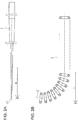
Fig. 2A illustrates a core shaft. -
Fig. 2B illustrates a coil body. -
Fig. 3 illustrates a guide wire according to another embodiment. -
Fig. 4 illustrates a guide wire according to still another embodiment. -
Fig. 5 illustrates a core shaft having another form. -
Fig. 6 illustrates a core shaft having another form. - As shown in
Fig. 1 , aguide wire 1A includes acore shaft 2 and acoil body 3, which are assembled to each other. To increase selectivity of the guide wire, a distal end portion k has a curved shape. - First, an external shape of the
core shaft 2 and an external shape of thecoil body 3 will be described in detail. - As shown in
Fig. 2A , thecore shaft 2 prior to mounting thereof has the shape of a tapered round bar whose distal-end side has a small diameter and whose proximal-end side has a larger diameter, and has what is called a linear shape over its entire length. That is, along a center line L1 in a long-axis direction of thecore shaft 2, a curvature X1 at at least a distal end portion m is equal to zero (X1 = 0) with respect to a proximal end of thecore shaft 2. - As shown in
Fig. 2B , thecoil body 3 is sparsely wound, and, at least a distal end portion n of thecoil body 3 is previously formed into a curved shape prior to mounting of thecoil body 3. That is, along a center line L2 in a long-axis direction of thecoil body 3, a curvature X2 at at least the distal end portion n is set in a range of at least X2 > 0 with respect to a proximal end of thecoil body 3. Here, when the curvature X2 is compared with the curvature X1 at the distal end portion m of thecore shaft 2, the curvature X1 is less than the curvature X2. - The
core shaft 2 and thecoil body 3 are each formed of, for example, a stainless alloy such as SUS304 or SUS316. - As shown in
Fig. 1 , thecoil body 3 covers the distal end portion m of thecore shaft 2, the distal end portion m of thecore shaft 2 and the distal end portion n of thecoil body 3 are secured to each other by atip portion 5 having a substantially semispherical shape, and the proximal end of thecoil body 3 is secured to thecore shaft 2 at asecuring portion 7, so that theguide wire 1A is formed. Thetip portion 5 and thesecuring portion 7 are formed by a publicly known technology (for example, bonding using an adhesive, soldering, or welding) using a publicly known material. - Here, as shown in
Fig. 1 , theguide wire 1A in which thecore shaft 2 and thecoil body 3 are mounted to each other is such that, along a center line L3 in the long-axis direction of theguide wire 1A, a curvature X3 at the distal end portion k is at least in a range of X3 < 0 with respect to the proximal end of theguide wire 1A. More specifically, the curvature X1 at the distal end portion m of thecore shaft 2, the curvature X2 at the distal end portion n of thecoil body 3, and the curvature X3 at the distal end portion k of theguide wire 1A satisfy the following relationship:
- Here, the curvature X1 of the
core shaft 2 corresponds to a first curvature according to the present invention. The curvature X2 of the coil body corresponds to a second curvature. The curvature X3 of theguide wire 1A corresponds to a third curvature. - Since the distal end portion k of the
guide wire 1A is curved, theguide wire 1A provides excellent selectivity in, for example, a blood vessel. In the case where theguide wire 1A is inserted into, for example, a stenotic lesion, when the distal end portion k is deformed into a linear shape, thecore shaft 2 itself approaches its original shape. Therefore, the amount of deformation of thecore shaft 2 is reduced, as a result of which resilient restoring force generated at thecore shaft 2 is reduced. Consequently, even if the distal end portion k of theguide wire 1A is deformed into a linear shape, jumping of thecore shaft 2 is reduced, so that excessive jumping of theguide wire 1A as a whole is prevented from occurring. In addition, since thecore shaft 2 and thecoil body 3 are each formed of a stainless alloy, a doctor can finely adjust the amount of curvature of the distal end portion k of theguide wire 1A, to adjust the distal end portion k to a desired curved shape. Further, since the stainless alloy is highly rigid, rotation transmission ability of the distal end portion k of theguide wire 1A is increased, so that selectivity is further increased. - The
coil body 3 is not limited to a single coil. As shown inFig. 3 , acoil body 31 including a multi-thread coil may be used. The multi-thread coil has excellent resiliency. Therefore, the curved shape of the distal end portion k of theguide wire 1A when theguide wire 1A is used is reliably restored, so that the selectivity is reliably maintained. In addition, since the multi-thread coil is such that a plurality of coil wires are twisted and wound, even if the curved shape is previously formed, gaps are not easily formed between the coil wires. Therefore, when thecoil body 31 is mounted to thecore shaft 2, thecore shaft 2 is easily inserted into thecoil body 31, so that the mounting can be smoothly performed. Consequently, the productivity ofguide wires 1A is increased. - The above-described structures described thus far may be modified as described below. Portions that correspond to those of the above-described embodiment will not be described below. They will be given the same reference numerals in the figures. Further, the features of the below-described modifications may be applied to the above-described embodiments individually or in any technically feasible combination.
- As shown in
Fig. 4 , aguide wire 1B according to a modification includes alinear core shaft 2 and acoil body 3 including a single coil. Aninner coil body 15 that covers at least a distal end portion m of thecore shaft 2 is provided at an inner side of a distal end portion n of thecoil body 3. Theinner coil body 15 includes a multi-thread coil. A distal end of theinner coil body 15 is caused to adhere to theaforementioned tip portion 5, and a proximal end of theinner coil body 15 is secured to thecore shaft 2 at a securingportion 17. The securingportion 17 is suitably formed by a publicly known technology that is the same as that used to form thetip portion 5 and the securingportion 7. Theinner coil body 15 is previously formed into a curved shape. A curvature X4 along a center line L4 in a long-axis direction of theinner coil body 15 prior to mounting thereof is set so as to be equal to a curvature X2 along a center line L2 at a distal end portion n of thecoil body 3 at the outer side. - When the
guide wire 1B includes theinner coil body 15, plastic deformation of a distal end portion k of theguide wire 1B is stably suppressed due to the restoring force of theinner coil body 15. Therefore, the selectivity of theguide wire 1B is further increased. The multi-thread coil of theinner coil body 15 has excellent resiliency. Therefore, the curved shape of the distal end portion k of theguide wire 1B when theguide wire 1B is used is reliably restored, so that the selectivity is reliably maintained. In addition, when the multi-thread coil is formed into a curved shape, gaps are not easily formed between the coil wires. Therefore, when theinner coil body 15 is mounted to thecore shaft 2, thecore shaft 2 is easily inserted into theinner coil body 15, so that the mounting can be smoothly performed. Consequently, productivity ofguide wires 1B is increased. - As shown in
Figs. 5A and 5B , adistal end portion 23 of acore shaft 21 may be formed into a flattened shape. Thecore shaft 21 in the mounted state is disposed so that one of the flat surfaces of thedistal end portion 23 faces the center of curvature of aguide wire 1C. Such a structure makes it possible to orient the distal end portion of theguide wire 1C, so that shaping of theguide wire 1C is more easily performed. Therefore, a doctor can finely adjust the amount of curvature of the distal end portion k (seeFig. 5A ) of theguide wire 1C, to adjust a distal end portion k to a desired curved shape. As a result, the selectivity of theguide wire 1C is further increased. - As shown in
Fig. 6 , a distal end portion m of acore shaft 25 prior to mounting thereof may be previously formed into a curved shape. More specifically, a curvature X1 at the distal end portion m of thecore shaft 25 satisfies the following relationship in the present invention:
- The
core shafts coil bodies core shafts coil bodies guide wires 1A to 1C is suppressed, thereby further increasing selectivity. - The present invention is not limited to the above-described embodiments, so that, obviously, design changes may be made and various combinations may be made as appropriate without departing from the gist of the present invention.
- For example, the curved shape of the distal end portion k of each of the
guide wires 1A to 1C may be modified as appropriate. The curved shape may obviously be, for example, an angular shape or a J shape. It is possible for the core shaft and thecoil bodies inner coil body 15 to have a curvature. When only theinner coil body 15 has a curvature, theinner coil body 15 is desirably a multi-thread coil body. In addition, thecoil bodies whole coil body 3 and thewhole coil body 31 may be formed into a curved shape (such as a C shape). Essentially, the distal end portion of thecoil body 3 and the distal end portion of thecoil body 31 may have any curved shape as long as the curved shape has the predetermined curvature X2 with respect to the center line L2 at the proximal end of thecoil body 3 and the proximal end of thecoil body 31.
Claims (10)
- A guide wire (1A, 1B, 1C) comprising:a core shaft (2, 21, 25) having a distal end portion (m) and a proximal end; anda coil body (3, 31) that covers at least the distal end portion (m) of the core shaft (2, 21, 25), the coil body (3, 31) having a distal end portion (n) and a proximal end, wherein the core shaft (2, 21, 25) and the coil body (3, 31) are mounted to each other so that a distal end portion (k) of the guide wire (1A, 1B, 1C) has, along a center line in a long-axis direction of the guide wire (1A, 1B, 1C), a defined curvature with respect to a proximal end of the guide wire (1A, 1B, 1C), characterized in thatthe distal end portion (m) of the core shaft (2, 21, 25) has, in a state prior to mounting the core shaft (2, 21, 25) and the coil body (3, 31) to each other, a first curvature with respect to the proximal end of the core shaft (2, 21, 25) along a center line in a long-axis direction thereof,at least the distal end portion (n) of the coil body (3, 31) has, in a state prior to mounting the core shaft (2, 21, 25) and the coil body (3, 31) to each other, a second curvature with respect to the proximal end of the coil body (3, 31) along a center line in a long-axis direction of the coil body (3, 31),the first curvature is less than the second curvature, andin the guide wire (1A, 1B, 1C), when the core shaft (2, 21, 25) and the coil body (3, 31) are mounted to each other, the distal end portion (m) of the core shaft (2, 21, 25) and the distal end portion (n) of the coil body (3, 31) are elastically deformed into a third curvature corresponding to the defined curvature of the distal end portion (k) of the guide wire (1A, 1B, 1C), the third curvature being less than the second curvature and greater than the first curvature.
- The guide wire (1A) according to Claim 1, wherein the coil body (31) is a multi-thread coil including a plurality of wires.
- The guide wire (1B) according to Claim 1 or 2,
wherein an inner side of at least the distal end portion (n) of the coil body (3, 31) is provided with an inner coil body (15) that covers at least the distal end portion (m) of the core shaft (2), the inner coil body (15) having a distal end portion and a proximal end, and
wherein, along a center line in a long-axis direction of the inner coil body (15), at least the distal end portion of the inner coil body (15) has the second curvature with respect to the proximal end of the inner coil body (15). - The guide wire (1B) according to Claim 3, wherein the inner coil body (15) is a multi-thread coil including a plurality of coil wires.
- The guide wire (1A, 1B, 1C) according to any of Claims 1 to 4, wherein the core shaft (2, 21, 25) and the coil body (3, 31) are each formed of a stainless alloy.
- The guide wire (1B) according to any of Claims 3 to 5, wherein the inner coil body (15) is formed of a stainless alloy.
- The guide wire (1A, 1B, 1C) according to any of Claims 1 to 6, wherein the core shaft (2, 21, 25) and the coil body (3, 31) are each formed of a pseudoelastic alloy.
- The guide wire (1A, 1B, 1C) according to any of Claims 1 to 7, wherein the first curvature of the core shaft (2, 21, 25) is zero.
- The guide wire (1C) according to any of Claims 1 to 8, wherein the distal end portion (23) of the core shaft (21) terminates, in a direction from the proximal end towards the distal end portion (23), in a flattened shape.
- A method of producing a guide wire (1A, 1B, 1C) according to any of Claims 1 to 9, comprising the step of:mounting a core shaft (2, 21, 25) having a distal end portion (m) and a proximal end, and a coil body (3, 31) having a distal end portion (n) and a proximal end, to each other so that a distal end portion (k) of the guide wire (1A, 1B, 1C) has, along a center line in a long-axis direction of the guide wire (1A, 1B, 1C), a defined curvature with respect to a proximal end of the guide wire (1A, 1B, 1C), characterized in thatthe distal end portion (m) of the core shaft (2, 21, 25) has, in a state prior to mounting the core shaft (2, 21, 25) and the coil body (3, 31) to each other, a first curvature with respect to the proximal end of the core shaft (2, 21, 25) along a center line in a long-axis direction thereof,at least the distal end portion (n) of the coil body (3, 31) has, in a state prior to mounting the core shaft (2, 21, 25) and the coil body (3, 31) to each other, a second curvature with respect to the proximal end of the coil body (3, 31) along a center line in a long-axis direction thereof,the first curvature is less than the second curvature, andwhen the core shaft (2, 21, 25) and the coil body (3, 31) are mounted to each other, the distal end portion (m) of the core shaft (2, 21, 25) and the distal end portion (n) of the coil body (3, 31) become elastically deformed into a third curvature corresponding to the defined curvature of the distal end portion (k) of the guide wire (1A, 1B, 1C), the third curvature being less than the second curvature and greater than the first curvature.
Applications Claiming Priority (1)
| Application Number | Priority Date | Filing Date | Title |
|---|---|---|---|
| JP2011074103A JP5709212B2 (en) | 2011-03-30 | 2011-03-30 | Guide wire |
Publications (2)
| Publication Number | Publication Date |
|---|---|
| EP2505225A2 true EP2505225A2 (en) | 2012-10-03 |
| EP2505225A3 EP2505225A3 (en) | 2012-10-10 |
Family
ID=45655521
Family Applications (1)
| Application Number | Title | Priority Date | Filing Date |
|---|---|---|---|
| EP12154709A Withdrawn EP2505225A3 (en) | 2011-03-30 | 2012-02-09 | Guide wire |
Country Status (4)
| Country | Link |
|---|---|
| US (1) | US20120253321A1 (en) |
| EP (1) | EP2505225A3 (en) |
| JP (1) | JP5709212B2 (en) |
| CN (1) | CN102727984A (en) |
Cited By (4)
| Publication number | Priority date | Publication date | Assignee | Title |
|---|---|---|---|---|
| WO2014110326A2 (en) * | 2013-01-10 | 2014-07-17 | The Cleveland Clinic Foundation | Coronary guidewire |
| EP2918306A1 (en) * | 2014-02-24 | 2015-09-16 | Asahi Intecc Co., Ltd. | Guide wire |
| USD741999S1 (en) | 2014-04-03 | 2015-10-27 | Asahi Intecc Co., Ltd. | Guidewire for a medical device |
| USD742000S1 (en) | 2014-04-24 | 2015-10-27 | Asahi Intecc Co., Ltd. | Guidewire for a medical device |
Families Citing this family (5)
| Publication number | Priority date | Publication date | Assignee | Title |
|---|---|---|---|---|
| JP6042080B2 (en) * | 2012-03-09 | 2016-12-14 | テルモ株式会社 | Guide wire |
| US11090465B2 (en) * | 2014-08-21 | 2021-08-17 | Boston Scientific Scimed, Inc. | Medical device with support member |
| JP2017120699A (en) * | 2015-12-28 | 2017-07-06 | ウシオ電機株式会社 | Conductor for high frequency and high frequency lightening-type light source deice |
| US10610308B2 (en) * | 2017-02-01 | 2020-04-07 | Acclarent, Inc. | Navigation guidewire with interlocked coils |
| EP4147743A4 (en) * | 2020-05-08 | 2024-01-24 | Asahi Intecc Co Ltd | Guide wire |
Citations (1)
| Publication number | Priority date | Publication date | Assignee | Title |
|---|---|---|---|---|
| JPH07255856A (en) | 1994-03-23 | 1995-10-09 | Kato Hatsujo Kaisha Ltd | Tip part shaping method of guide wire for medical care |
Family Cites Families (16)
| Publication number | Priority date | Publication date | Assignee | Title |
|---|---|---|---|---|
| US3749086A (en) * | 1972-07-24 | 1973-07-31 | Medical Evaluation Devices & I | Spring guide with flexible distal tip |
| US4003369A (en) * | 1975-04-22 | 1977-01-18 | Medrad, Inc. | Angiographic guidewire with safety core wire |
| US4020829A (en) * | 1975-10-23 | 1977-05-03 | Willson James K V | Spring guide wire with torque control for catheterization of blood vessels and method of using same |
| US4854330A (en) * | 1986-07-10 | 1989-08-08 | Medrad, Inc. | Formed core catheter guide wire assembly |
| US4763647A (en) * | 1987-01-06 | 1988-08-16 | C. R. Bard, Inc. | Dual coil steerable guidewire |
| US5211183A (en) * | 1987-05-13 | 1993-05-18 | Wilson Bruce C | Steerable memory alloy guide wires |
| US5154705A (en) * | 1987-09-30 | 1992-10-13 | Lake Region Manufacturing Co., Inc. | Hollow lumen cable apparatus |
| US4971490A (en) * | 1988-03-01 | 1990-11-20 | National Standard Company | Flexible guide wire with improved mounting arrangement for coil spring tip |
| US4932419A (en) * | 1988-03-21 | 1990-06-12 | Boston Scientific Corporation | Multi-filar, cross-wound coil for medical devices |
| JPH04108456A (en) * | 1990-08-30 | 1992-04-09 | Terumo Corp | Guide wire for medical treatment |
| US5243996A (en) * | 1992-01-03 | 1993-09-14 | Cook, Incorporated | Small-diameter superelastic wire guide |
| JP4358590B2 (en) * | 2002-11-13 | 2009-11-04 | 株式会社ハイレックスコーポレーション | Manufacturing method of medical guide wire |
| JP2005185386A (en) * | 2003-12-25 | 2005-07-14 | Asahi Intecc Co Ltd | Medical guide wire |
| JP2005342470A (en) * | 2004-06-03 | 2005-12-15 | Ys Medical:Kk | Medical guide wire |
| JP3802043B1 (en) * | 2005-06-06 | 2006-07-26 | 朝日インテック株式会社 | Baking mold and guide wire manufacturing method using the baking mold |
| JP4845144B2 (en) * | 2008-03-24 | 2011-12-28 | 朝日インテック株式会社 | Manufacturing method of medical guide wire |
-
2011
- 2011-03-30 JP JP2011074103A patent/JP5709212B2/en active Active
-
2012
- 2012-02-09 EP EP12154709A patent/EP2505225A3/en not_active Withdrawn
- 2012-03-12 CN CN201210063118.XA patent/CN102727984A/en active Pending
- 2012-03-22 US US13/427,117 patent/US20120253321A1/en not_active Abandoned
Patent Citations (1)
| Publication number | Priority date | Publication date | Assignee | Title |
|---|---|---|---|---|
| JPH07255856A (en) | 1994-03-23 | 1995-10-09 | Kato Hatsujo Kaisha Ltd | Tip part shaping method of guide wire for medical care |
Cited By (6)
| Publication number | Priority date | Publication date | Assignee | Title |
|---|---|---|---|---|
| WO2014110326A2 (en) * | 2013-01-10 | 2014-07-17 | The Cleveland Clinic Foundation | Coronary guidewire |
| WO2014110326A3 (en) * | 2013-01-10 | 2014-10-16 | The Cleveland Clinic Foundation | Coronary guidewire |
| EP2918306A1 (en) * | 2014-02-24 | 2015-09-16 | Asahi Intecc Co., Ltd. | Guide wire |
| US10471237B2 (en) | 2014-02-24 | 2019-11-12 | Asahi Intecc Co., Ltd. | Guide wire |
| USD741999S1 (en) | 2014-04-03 | 2015-10-27 | Asahi Intecc Co., Ltd. | Guidewire for a medical device |
| USD742000S1 (en) | 2014-04-24 | 2015-10-27 | Asahi Intecc Co., Ltd. | Guidewire for a medical device |
Also Published As
| Publication number | Publication date |
|---|---|
| EP2505225A3 (en) | 2012-10-10 |
| CN102727984A (en) | 2012-10-17 |
| JP2012205795A (en) | 2012-10-25 |
| US20120253321A1 (en) | 2012-10-04 |
| JP5709212B2 (en) | 2015-04-30 |
Similar Documents
| Publication | Publication Date | Title |
|---|---|---|
| EP2505225A2 (en) | Guide wire | |
| JP4993632B2 (en) | Medical guidewire | |
| JP5013547B2 (en) | Medical guidewire | |
| JP4863321B2 (en) | Medical guidewire | |
| EP2417999A1 (en) | Guidewire with bent portion fixed with a fixing member | |
| JP2009000337A (en) | Medical guide wire | |
| CN102343121A (en) | Guidewire | |
| EP2921195A1 (en) | Guide wire | |
| JP2013106854A (en) | Guidewire | |
| EP3061486A1 (en) | Medical guide wire | |
| JP2015083086A (en) | Coil body and guide wire | |
| JP5229830B2 (en) | Medical guidewire | |
| CN112423825A (en) | Guide wire | |
| JP7050175B2 (en) | Medical equipment | |
| JP5459723B2 (en) | Medical guidewire | |
| JP6813243B2 (en) | Guide wire | |
| JP2019146705A (en) | Guide wire | |
| JP2010252938A (en) | Guide wire | |
| EP4147743A1 (en) | Guide wire | |
| JP2017164200A (en) | Guide wire | |
| JP2014079632A (en) | Medical guide wire | |
| JP5376542B2 (en) | Medical guidewire | |
| WO2021038770A1 (en) | Guide wire | |
| WO2020003503A1 (en) | Guide wire | |
| JP2012005520A (en) | Medical guide wire |
Legal Events
| Date | Code | Title | Description |
|---|---|---|---|
| PUAL | Search report despatched |
Free format text: ORIGINAL CODE: 0009013 |
|
| PUAI | Public reference made under article 153(3) epc to a published international application that has entered the european phase |
Free format text: ORIGINAL CODE: 0009012 |
|
| AK | Designated contracting states |
Kind code of ref document: A2 Designated state(s): AL AT BE BG CH CY CZ DE DK EE ES FI FR GB GR HR HU IE IS IT LI LT LU LV MC MK MT NL NO PL PT RO RS SE SI SK SM TR |
|
| AX | Request for extension of the european patent |
Extension state: BA ME |
|
| AK | Designated contracting states |
Kind code of ref document: A3 Designated state(s): AL AT BE BG CH CY CZ DE DK EE ES FI FR GB GR HR HU IE IS IT LI LT LU LV MC MK MT NL NO PL PT RO RS SE SI SK SM TR |
|
| AX | Request for extension of the european patent |
Extension state: BA ME |
|
| RIC1 | Information provided on ipc code assigned before grant |
Ipc: A61M 25/09 20060101AFI20120831BHEP |
|
| STAA | Information on the status of an ep patent application or granted ep patent |
Free format text: STATUS: THE APPLICATION IS DEEMED TO BE WITHDRAWN |
|
| 18D | Application deemed to be withdrawn |
Effective date: 20130411 |