EP2505114A2 - Staubfangvorrichtung - Google Patents
Staubfangvorrichtung Download PDFInfo
- Publication number
- EP2505114A2 EP2505114A2 EP12161488A EP12161488A EP2505114A2 EP 2505114 A2 EP2505114 A2 EP 2505114A2 EP 12161488 A EP12161488 A EP 12161488A EP 12161488 A EP12161488 A EP 12161488A EP 2505114 A2 EP2505114 A2 EP 2505114A2
- Authority
- EP
- European Patent Office
- Prior art keywords
- dust
- flow
- air
- collecting device
- dust collecting
- Prior art date
- Legal status (The legal status is an assumption and is not a legal conclusion. Google has not performed a legal analysis and makes no representation as to the accuracy of the status listed.)
- Granted
Links
Images

Classifications
-
- A—HUMAN NECESSITIES
- A47—FURNITURE; DOMESTIC ARTICLES OR APPLIANCES; COFFEE MILLS; SPICE MILLS; SUCTION CLEANERS IN GENERAL
- A47L—DOMESTIC WASHING OR CLEANING; SUCTION CLEANERS IN GENERAL
- A47L9/00—Details or accessories of suction cleaners, e.g. mechanical means for controlling the suction or for effecting pulsating action; Storing devices specially adapted to suction cleaners or parts thereof; Carrying-vehicles specially adapted for suction cleaners
- A47L9/0081—Means for exhaust-air diffusion; Means for sound or vibration damping
-
- A—HUMAN NECESSITIES
- A47—FURNITURE; DOMESTIC ARTICLES OR APPLIANCES; COFFEE MILLS; SPICE MILLS; SUCTION CLEANERS IN GENERAL
- A47L—DOMESTIC WASHING OR CLEANING; SUCTION CLEANERS IN GENERAL
- A47L5/00—Structural features of suction cleaners
- A47L5/12—Structural features of suction cleaners with power-driven air-pumps or air-compressors, e.g. driven by motor vehicle engine vacuum
- A47L5/22—Structural features of suction cleaners with power-driven air-pumps or air-compressors, e.g. driven by motor vehicle engine vacuum with rotary fans
- A47L5/24—Hand-supported suction cleaners
-
- A—HUMAN NECESSITIES
- A47—FURNITURE; DOMESTIC ARTICLES OR APPLIANCES; COFFEE MILLS; SPICE MILLS; SUCTION CLEANERS IN GENERAL
- A47L—DOMESTIC WASHING OR CLEANING; SUCTION CLEANERS IN GENERAL
- A47L9/00—Details or accessories of suction cleaners, e.g. mechanical means for controlling the suction or for effecting pulsating action; Storing devices specially adapted to suction cleaners or parts thereof; Carrying-vehicles specially adapted for suction cleaners
- A47L9/10—Filters; Dust separators; Dust removal; Automatic exchange of filters
- A47L9/14—Bags or the like; Rigid filtering receptacles; Attachment of, or closures for, bags or receptacles
-
- A—HUMAN NECESSITIES
- A47—FURNITURE; DOMESTIC ARTICLES OR APPLIANCES; COFFEE MILLS; SPICE MILLS; SUCTION CLEANERS IN GENERAL
- A47L—DOMESTIC WASHING OR CLEANING; SUCTION CLEANERS IN GENERAL
- A47L9/00—Details or accessories of suction cleaners, e.g. mechanical means for controlling the suction or for effecting pulsating action; Storing devices specially adapted to suction cleaners or parts thereof; Carrying-vehicles specially adapted for suction cleaners
- A47L9/10—Filters; Dust separators; Dust removal; Automatic exchange of filters
- A47L9/14—Bags or the like; Rigid filtering receptacles; Attachment of, or closures for, bags or receptacles
- A47L9/1409—Rigid filtering receptacles
Definitions
- Embodiments of the invention are concerned with vacuum cleaners and in particular with new concepts for dust collection devices used in vacuum cleaners.
- Vacuum cleaners and hand vacuum cleaners exist in great variety and variety of shapes on the market.
- Vacuum cleaners typically have a vacuum cleaner nozzle with a nozzle mouth for sucking in dirt particles or air, as well as a dust housing, within which different dust retention components, such as filter bags, are arranged.
- the international patent application WO 99/05954 Proposes to prevent complete coking of the filter with coarse dirt by a perforated and shaped spacer is placed between a filter bag and an air outlet to the blower in a dust chamber of a vacuum cleaner that the coarse debris can enforce only part of the filter during normal operation ,
- the suction power is reduced and in the WO 99/05954 proposed method brings for fine dirt, which is a common cause of clogging of the fine pores of a filter, no improvement.
- the operation of the vacuum cleaner described depends on the orientation of the device.
- the dust container of some embodiments of the invention has a plurality of flow openings or flow openings to a dust enclosure tightly enclosing dust housing, so that acting in the dust housing negative pressure can serve to suck through the flow openings air, via an air inlet in the dust container flows.
- the plurality of flow openings each allow the use of a different flow path for the air, wherein different flow paths may be different in length or have a different flow resistance. That is, the air molecules travel different distances along different flow paths, or different power would be required to transport the air molecules along the different flow paths if the flow openings were identical.
- the cross-section of the flow openings varies such that it is larger for one or all of the flow paths with a higher flow resistance than for one or all flow paths with a lower flow resistance. In some embodiments, the cross section of the flow openings varies such that it is larger for longer flow paths than for shorter flow paths.
- some embodiments of the invention have a nozzle with a nozzle mouth and a nozzle outlet, which is immediately followed by a dust housing, which has an adjacent to the nozzle outlet, tapering from the nozzle outlet to a dust chamber opening inlet funnel.
- the nozzle exit is thus coupled directly to a tapered inlet funnel in the dust space or the dust housing, so that a maximum cross section at the interface or a connection point between the nozzle and the dust housing can be used, which in turn can significantly reduce the flow resistance.
- the tapered inlet funnel can still be achieved in a streamlined manner, a direct or indirect flow of a filter element.
- the inlet hopper has the shape of a truncated cone to achieve a uniform, streamlined reduction in cross-section.
- a dust container or a dust container forming arrangement located within the dust housing is a dust container or a dust container forming arrangement, wherein the inlet funnel is disposed within and surrounded by the dust container so that a dust-receiving volume is formed between an outer wall of the inlet funnel and an inner wall of the dust container. Due to the combination of the tapered inlet funnel and the surrounding dust container, a dust trap is formed into which the coarse dirt entering the housing can enter and from which the coarse dirt can no longer escape during normal operation.
- the inlet hopper and the dust container are shaped in the form of concentric truncated cones, so that the most streamlined and efficient operation of the dust trap and the dust container are ensured can, since this surrounds the inlet funnel completely and with a uniform opening cross-section.
- the dust collection device further includes a baffle that extends in the dust container toward the dust space opening and can redirect the airflow into the dust bin in a streamlined and energy efficient manner.
- the baffle has the shape of a cone or a rounded surface or surface to provide the deflection in a streamlined and energy efficient manner.
- the side of the dust container facing the inlet funnel can additionally be provided with a filter element in order to retain fine dust particles in the dust-receiving volume or in the dust space.
- the dust container for this purpose on a plurality of projections which extend into the dust-receiving volume and which are suitable for receiving a filter element, so that due to the elevations a uniform flow of the filter element from the back, ie from the side , of which a negative pressure to achieve the suction force, can be achieved.
- a filter can be used without a large variation in the suction power by adding the filter, which causes an increased flow resistance through the filter.
- the nozzle from the nozzle mouth to the nozzle outlet is designed or has such an inner cross-section that the flow direction of the sucked by the nozzle air at the nozzle outlet is substantially tangential to an inner wall of the inlet funnel. This may, in some embodiments, cause the flow to flow with less turbulence along the inlet funnel and up to an outlet opening of the dust housing.
- the use of laminar flow significantly lowers flow resistance, which can contribute to further reducing the required engine power.
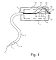
- FIG. 1 shows a schematic sectional view of an embodiment of a dust collecting device for a vacuum cleaner.
- a nozzle 4 and a vacuum cleaner 4 shown, which sucks polluted air via its nozzle mouth 8 and this passes through the nozzle outlet 10 by means of a vacuum cleaner hose 11 to an air inlet 14 of a dust container 16.
- the dust container 16 is disposed within a dust housing 6.
- the dust housing 6 in turn has an air outlet 20, which can be connected, for example with a fan assembly or with a blower to generate a negative pressure within the dust housing 6, via flow openings 18 a to 18 e, extending through the outer wall of the dust container 16 up to extend the dust housing 6 acts on the air inlet 14, so that contaminated air can be sucked into the dust container 16.
- an air outlet 20 can be connected, for example with a fan assembly or with a blower to generate a negative pressure within the dust housing 6, via flow openings 18 a to 18 e, extending through the outer wall of the dust container 16 up to extend the dust housing 6 acts on the air inlet 14, so that contaminated air can be sucked into the dust container 16.
- the plurality of flow openings 18a to 18e allow different flow paths 19a to 19d, along which air can flow from the air inlet 14 to the air outlet 20. Depending on the geometric conditions, the different flow paths have different flow resistance.
- polluted air primarily passes along the geometry of the flow path 19a to flow into the interior of the dust container 16, so that possibly the flow openings 18a and 18b or arranged upstream of these flow openings filter or a filter element, which covers the flow openings 18a and 18b along the flow paths containing these flow openings, is added first.
- the larger cross-sections of the flow openings 18c and 18d compensate for the higher flow resistance of the flow paths 19c and 19d associated with these flow openings 18c and 18d, so that even with a successive clogging of the filter or flow openings, the total flow resistance approximately follows the path traveled by the air can remain constant, so that only due to the geometric arrangement or the geometric shape of the dust container 16, a constant suction force over a long period of operation can be ensured.
- FIGS. 2 and 3 show an embodiment of a dust collecting device of more complex geometry, which is optimized in terms of other fluidic aspects.
- the illustrated dust collecting device for a vacuum cleaner or for a hand vacuum cleaner is mounted on a fan assembly 21.
- a fan assembly 21 For the sake of clarity, a more detailed description of the fan assembly 21 will be omitted below, the exact Embodiment with respect to the dust collector itself is not essential.
- the dust collecting device comprises a nozzle 4 and a dust housing 6.
- the dust housing 6 may be formed in one piece or in several parts and consist of several functional units or components, which will be explained in more detail below.
- the nozzle 4 has a nozzle mouth 8, which in the present case has a rectangular cross-section, and a nozzle outlet 10, on which the nozzle 4 directly adjoins the dust housing 6 or an inlet funnel 12 located in the dust housing 6.
- the nozzle outlet 10 has a circular cross-section in order to allow a flow-efficient transition to the inlet funnel 12.
- the cross section of the nozzle mouth 8 in FIG. 2 is rectangular, of course, any other cross section are possible, for example, trapezoidal, round or elliptical.
- the inlet funnel 12 is frusto-conical and tapers in the shape of a cone from the nozzle exit 10 to a dust chamber opening or to the air inlet 14. At the air inlet 14 of the inlet funnel 12 ends, so that guided by the inlet funnel 12 air at the air inlet 14in a can reach dust-receiving volume.
- the dust-receiving volume is formed between an outside of the inlet hopper 12 and an inside wall of a dust container 16.
- the dust container 16 in turn is part of the dust housing 6 and in the present case designed in one piece with the dust housing 6.
- the individual in FIG. 2 Of course, components that are illustrated can also be designed in several parts.
- the dust housing 6 is also frusto-conical and arranged concentrically with the inlet funnel 12 and has a plurality of flow openings 18a to 18e through which aspirated air can flow from the dust container 16 into the dust housing 6 or into the volume between dust housing 6 and dust container 16. from where it can reach the fan assembly 2 via an air outlet 20.
- the air emerging from the dust chamber opening or from the air inlet 14 is deflected by means of a cone-shaped deflecting body 22 in order to reach the dust-receiving volume between the inlet funnel 12 and the dust container 16.
- This shape of the deflector 22 promotes a streamlined deflection of the air.
- the in FIG. 2 illustrated embodiment further includes an optional filter 24 which is disposed on an inner wall of the dust container 16.
- the dust container 16 for this purpose has a plurality of extending into the dust-receiving volume elevations or webs 26, which allow a uniform flow against the filter or a uniform flow behind the filter 24.
- the baffle 22 is shown as part of the filter, this may be formed in alternative embodiments, part of the dust container 16 or as a separate element.
- a cross-section of the flow openings 18a to 18d increases with the length of the flow path belonging to the individual flow openings (the path leading from the air inlet 14 to the air outlet 20 via the relevant flow opening) in order to be able to ensure a suction force that is as constant as possible over the operating period.
- the deflecting body 22 itself and the surrounding top surface of the frusto-conical dust container 16 can also have further flow openings of suitable cross section.
- the inner cross section of the nozzle is designed such that the air is rotated so that it tangential or approximately tangential to the surface of the inlet funnel 12 into the inlet funnel 12 and substantially in the form of a spiral up to the air inlet 14 flows, which can ensure a uniform flow of a filter. This in turn can lead to a high constancy of the suction power when the filter is evenly added.
- a filter may be arranged directly on the inner walls of the inlet funnel 12 for this purpose.
- FIGS. 2 and 3 show FIGS. 2 and 3 a dust collecting device in which a long funnel-shaped channel leads from a nozzle far into the dust chamber.
- the filter bag with large inlet opening is formed around the inlet funnel.
- the dust chamber cone is designed double-walled and equipped with increasing the flow end hole openings as a motor protection filter to ensure the longest possible constant suction even with high dust loading. Between filter and dust cone, ribs are attached, which ensure a uniform back flow of the filter.
- a deflector cone directly behind the inlet opening in the dust chamber directs the air flow to the outside, thus avoiding the falling back of the dirt in the nozzle area.
- a closure cap for example in the form of a ball with a through hole, prevent falling out of dirt. This may, according to some embodiments automatically close and open when the device is turned on or when a negative pressure is applied to the input of the dust container. Behind the perforated screen or behind the dust container with the flow openings, the flow is deflected and passed in a slowly tapering funnel to the blower opening 20.
- a suction channel within the nozzle gradually tapers and twists to a tangential entrance into the dust space.
- the flow can thus run in a uniform spiral along the filter bag wall and turn at the end funnel-shaped into a fan opening.
- filters for dust collecting devices can be produced from a wide variety of conventional filter materials, nonwovens or the like.
- filters for a dust collecting device can be used in any other geometries, for example, spherical, cylindrical or in the form of a truncated cone.
- a filter for a dust collecting device in the FIG. 2 shown type have a from the air inlet 14 opposite side of the dust container in the direction of the air inlet 14 extending and tapered deflecting body.
- Such filters may allow for different conditions different shapes of the baffles and possibly already have a filter function itself.
Landscapes
- Engineering & Computer Science (AREA)
- Mechanical Engineering (AREA)
- Filters For Electric Vacuum Cleaners (AREA)
Abstract
Description
- Ausführungsbeispiele der Erfindung befassen sich mit Staubsaugern und insbesondere mit neuen Konzepten für in Staubsaugern verwendete Staubfangvorrichtungen.
- Staubsauger und Handstaubsauger existieren in großer Vielzahl und Formenvielfalt am Markt. Staubsauger weisen dabei typischerweise eine Staubsaugerdüse mit einem Düsenmund zum Einsaugen von Schmutzpartikeln bzw. von Luft auf, sowie ein Staubgehäuse, innerhalb dessen unterschiedliche der Rückhaltung von Staub dienende Komponenten, wie beispielsweise Filterbeutel, angeordnet sind.
- Um eine Saugleistung während der Verwendungsdauer eines Filterbeutels möglichst lange konstant zu halten, kann eine Regelung der Saugleistung vorgesehen werden, die einen Leistungsabfall durch ein Verstopfen oder ein Zusetzen des Filters durch eine automatisierte Erhöhung der Motorleistung kompensiert. Dieses Vorgehen ist jedoch äußerst aufwendig und teuer. Auch wird dazu häufig der einen Staubsauger antreibende Elektromotor größer dimensioniert als erforderlich, um eine Reserve für die Regelung aufzuweisen. Dies kann zu unerwünschten höheren Energiekosten führen. Bei Handstaubsaugern, die häufig akkubetrieben sind, kann eine solche Erhöhung der Motorleistung zu einer verringerten Saugzeit des Gerätes führen, was die Anwendbarkeit eines Handstaubsaugers insgesamt negativ beeinflussen kann.
- Die internationale Patentanmeldung
WO 99/05954 WO 99/05954 - Somit besteht das Bedürfnis, nach einfacheren und universelleren Möglichkeiten zu suchen, eine gute Konstanz der Saugleistung eines Staubsaugers zu erzielen.
- Zum Absaugen der gereinigten Luft weist der Staubbehälter einiger Ausführungsbeispiele der Erfindung eine Mehrzahl von Strömungsöffnungen bzw. Strömungsdurchbrüchen zu einem den Staubbehälter dicht umschließenden Staubgehäuse auf, sodass ein in dem Staubgehäuse wirkender Unterdruck dazu dienen kann, durch die Strömungsöffnungen Luft anzusaugen, die über einen Lufteinlass in den Staubbehälter strömt. Die Mehrzahl von Strömungsöffnungen ermöglichen jeweils die Verwendung eines anderen Strömungswegs für die Luft, wobei unterschiedliche Strömungswege unterschiedlich lang sein beziehungsweise einen unterschiedlichen Strömungswiderstand aufweisen können. Das heißt, die Luftmoleküle legen entlang unterschiedlicher Strömungswege unterschiedliche Strecken zurück bzw. es wäre eine unterschiedliche Leistung bzw. Energie erforderlich, um die Luftmoleküle entlang der unterschiedlichen Strömungswege zu transportieren, wenn die Strömungsöffnungen identisch wären. Der Querschnitt der Strömungsöffnungen variiert jedoch derart, dass dieser für einen oder alle Strömungswege mit einem höheren Strömungswiderstand größer ist als für einen oder alle Strömungswege mit einem niedrigeren Strömungswiderstand. Bei einigen Ausführungsbeispielen variiert der Querschnitt der Strömungsöffnungen derart, dass dieser für längere Strömungswege größer ist als für kürzere Strömungswege.
- Dies kann bewirken, dass eine Saugleistung bzw. ein Saugkraft eines mittels einer solchen Staubfangvorrichtung ausgerüsteten Staubsaugers während des Betriebes lange konstant bleibt, auch wenn sich beispielsweise ein Filterelement in dem Staubbehälter sukzessive derart zusetzt, das zunächst die Strömungswege mit einem niedrigeren Strömungswiderstand bzw. die kürzeren Strömungswege durch das zugesetzte Filter unterbrochen werden. Mit anderen Worten wird das durch das Zusetzen eines Filters oder der Strömungsöffnungen verursachte Verwenden längerer Strömungswege, welches möglicherweise zu einem erhöhten Strömungswiderstand führen könnte, durch Strömungsöffnungen größeren Querschnitts kompensiert, so dass eine hohe Saugkraftkonstanz über die Verwendungszeit erzielt werden kann.
- Bei einigen Ausführungsbeispielen der vorliegenden Erfindung wird ferner eine Strömungsoptimierung weiterer Komponenten einer Staubfangvorrichtung, beispielsweise der Düse und des sich an diese anschließenden Staubgehäuses vorgenommen. So weisen einige Ausführungsbeispiele der Erfindung eine Düse mit einem Düsenmund und einem Düsenausgang auf, an den sich unmittelbar ein Staubgehäuse anschließt, das einen an den Düsenausgang angrenzenden, sich von dem Düsenausgang bis zu einer Staubraumöffnung verjüngenden Einlasstrichter aufweist. Der Düsenausgang ist also unmittelbar mit einem sich verjüngenden Einlasstrichter in dem Staubraum bzw. dem Staubgehäuse gekoppelt, so dass ein maximaler Querschnitt an der Schnittstelle bzw. einer Verbindungsstelle zwischen der Düse und dem Staubgehäuse genutzt werden kann, was wiederum den Strömungswiderstand erheblich reduzieren kann. Gleichzeitig kann bei einigen Ausführungsbeispielen mittels des sich verjüngenden Einlasstrichters trotzdem auf strömungsgünstige Art und Weise eine direkte oder indirekte Anströmung eines Filterelements erreicht werden. Bei einigen Ausführungsbeispielen weist der Einlasstrichter die Form eines Kegelstumpfes auf, um eine gleichmäßige, strömungsgünstige Verringerung des Querschnitts zu erzielen.
- Bei einigen Ausführungsbeispielen befindet sich innerhalb des Staubgehäuses ein Staubbehälter bzw. eine einen Staubbehälter formende Anordnung, wobei der Einlasstrichter innerhalb des Staubbehälters angeordnet und von diesem umgeben ist, so dass zwischen einer Außenwand des Einlasstrichters und einer Innenwand des Staubbehälters ein staubaufnehmendes Volumen gebildet wird. Durch die Kombination des sich verjüngenden Einlasstrichters und des diesen umgebenden Staubbehälters wird eine Staubfalle gebildet, in die in das Gehäuse eindringender Grobschmutz gelangen und aus dieser der Grobschmutz im normalen Betrieb nicht mehr entweichen kann.
- Bei einigen Ausführungsbeispielen sind der Einlasstrichter und der Staubbehälter in Form konzentrischer Kegelstümpfe geformt, so dass eine möglichst strömungsgünstige und effiziente Betriebsweise der Staubfalle bzw. des Staubbehälters sichergestellt werden kann, da dieser den Einlasstrichter vollständig und mit gleichmäßigen Öffnungsquerschnitt umgibt.
- Bei einigen Ausführungsbeispielen weist die Staubfangvorrichtung ferner einen Ablenkkörper auf, der sich in dem Staubbehälter in Richtung der Staubraumöffnung erstreckt und die Luftströmung strömungsgünstig und energieeffizient in den Staubbehälter umleiten kann. Bei einigen Ausführungsbeispielen weist der Ablenkkörper die Form eines Kegels bzw. eines abgerundeten Kegels oder einer Kugeloberfläche auf, um die Ablenkung strömungsgünstig und energieeffizient zu bewirken.
- Bei einigen Ausführungsbeispielen kann die dem Einlasstrichter zugewandte Seite des Staubbehälters zusätzlich mit einem Filterelement versehen sein, um Feinstaubpartikel in dem staubaufnehmenden Volumen bzw. in dem Staubraum zurückzuhalten. Bei einigen weiteren Ausführungsbeispielen weist der Staubbehälter zu diesem Zweck eine Mehrzahl von Erhebungen auf, die sich in das staubaufnehmende Volumen erstrecken und die zur Aufnahme eines Filterelements geeignet sind, so dass aufgrund der Erhebungen eine gleichmäßige Anströmung des Filterelements von der Rückseite, also von der Seite, von der ein Unterdruck zur Erzielung der Saugkraft wirkt, erzielt werden kann. Ein solcher Filter kann Verwendet werden, ohne dass ein große Variation der Saugleistung durch ein Zusetzen des Filters, das einen erhöhten Strömungswiderstand durch den Filter verursacht, erfolgt.
- Bei weiteren Ausführungsbeispielen ist die Düse vom Düsenmund bis zum Düsenausgang derart gestaltet bzw. weist einen derartigen inneren Querschnitt auf, dass die Strömungsrichtung der mittels der Düse angesaugten Luft am Düsenausgang im Wesentlichen tangential zu einer Innenwand des Einlasstrichters verläuft. Dies kann bei einigen Ausführungsbeispielen dazu führen, dass die Strömung mit geringeren Turbulenzen entlang des Einlasstrichters und bis zu einer Auslassöffnung des Staubgehäuses verlaufen kann. Die Verwendung einer laminaren Strömung erniedrigt den Strömungswiderstand signifikant, was zu einer weiteren Reduzierung der erforderlichen Motorleistung beitragen kann.
- Einige Ausführungsbeispiele der Erfindung werden nachfolgend, bezugnehmend auf die beigefügten Figuren, näher erläutert. Es zeigen:
-
Fig. 1 eine schematische Schnittansicht eines Ausführungsbeispiels einer Staubfangvorrichtung; -
Fig. 2 ein weiteres Ausführungsbeispiel einer Staubfangvorrichtung in einer perspektivischen Schnittansicht; und -
Fig. 3 eine zweidimensionale Schnittansicht des Ausführungsbeispiels vonFig. 2 ; -
Figur 1 zeigt eine schematische Schnittansicht eines Ausführungsbeispiels einer Staubfangvorrichtung für einen Staubsauger. Zum besseren Verständnis ist inFigur 1 zusätzlich eine Düse 4 bzw. eine Staubsaugerdüse 4 dargestellt, die über ihren Düsenmund 8 verschmutzte Luft ansaugt und diese über den Düsenausgang 10 mittels eines Staubsaugerschlauches 11 an einen Lufteinlass 14 eines Staubbehälters 16 leitet. Der Staubbehälter 16 ist innerhalb eines Staubgehäuses 6 angeordnet. Das Staubgehäuse 6 wiederum weist einen Luftauslass 20 auf, der beispielsweise mit einer Gebläseanordnung bzw. mit einem Gebläse verbunden werden kann, um einen Unterdruck innerhalb des Staubgehäuses 6 zu erzeugen, der über Strömungsöffnungen 18a bis18e, die sich durch die Außenwand des Staubbehälters 16 bis zu dem Staubgehäuse 6 erstrecken, auf den Lufteinlass 14 wirkt, so dass verunreinigte Luft in den Staubbehälter 16 gesaugt werden kann. - Die Mehrzahl von Strömungsöffnungen 18a bis 18e ermöglichen unterschiedliche Strömungswege 19a bis 19d, entlang derer Luft von dem Lufteinlass 14 zu dem Luftauslass 20 strömen kann. Je nach den geometrischen Gegebenheiten weisen die unterschiedlichen Strömungswege unterschiedliche Strömungswiderstände auf. Bei der in
Figur 1 gezeigten Anordnung wird eine verschmutzte Luft aufgrund der Geometrie primär entlang des Strömungsweges 19a in das Innere des Staubbehälters 16 strömen, so dass möglicherweise die Strömungsöffnungen 18a und 18b bzw. ein vor diesen Strömungsöffnungen angeordneter Filter bzw. ein Filterelement, das die Strömungsöffnungen 18a und 18b entlang der diese Strömungsöffnungen enthaltenden Strömungswege verdeckt, zuerst zugesetzt wird. Da Luft dann nicht mehr durch die zugesetzten Filterteile und somit auch nicht durch die zu diesen Filterteilen korrespondierenden Strömungsöffnungen strömen kann, wird die Luft durch alternative Strömungsöffnungen entlang eines oder mehrerer der weiteren gezeigten Strömungswege strömen. Die alternativen Strömungswege 19c und 19d bedingen jedoch eine zusätzliche Umlenkung des Luftstroms und sind darüber hinaus länger als die Strömungswege 19a und 19b. Durch die größeren Querschnitte der Strömungsöffnungen 18c und 18d wird der höhere Strömungswiderstand der diesen Strömungsöffnungen 18c und 18d zugeordneten Strömungswege 19c und 19d jedoch kompensiert, so dass selbst bei einem sukzessiven Zusetzen des Filters bzw. der Strömungsöffnungen der Gesamtströmungswiderstand entlang des von der Luft zurückgelegten Weges näherungsweise konstant bleiben kann, so dass allein aufgrund der geometrischen Anordnung bzw. der geometrischen Gestalt des Staubbehälters 16 eine konstante Saugkraft über eine lange Betriebsdauer sichergestellt werden kann. - Wenngleich aus Gründen der Darstellbarkeit die Geometrie des in
Figur 1 gezeigten Staubbehälters einfach und quaderförmig gewählt ist, versteht es sich von selbst, dass beliebige andere, beispielsweise zylinderförmige oder kugelförmige Geometrien verwendet werden können. Dabei kann der Querschnitt der Strömungsöffnungen unter Beachtung der strömungsmechanischen Grundsätze an die jeweils gewählte Form und die Positionierung des Lufteinlasses 14 bzw. des Luftauslasses 20 derart angepasst werden, dass für einen überwiegenden Teil der Strömungsöffnungen gilt, dass Strömungsöffnungen, die zu Strömungswegen mit höheren Strömungswiderständen korrespondieren, einen größeren Querschnitt aufweisen. Dies ist für einen Fachmann bei jeder Geometrie ohne weiteres möglich. - Die
Figuren 2 und 3 zeigen ein Ausführungsbeispiel einer Staubfangvorrichtung komplexerer Geometrie, die hinsichtlich weiterer strömungstechnischer Aspekte optimiert ist. Die dargestellte Staubfangvorrichtung für einen Staubsauger bzw. für einen Handstaubsauger ist an eine Gebläseanordnung 21 montiert. Aus Gründen der Klarheit wird nachfolgend auf eine detailliertere Beschreibung der Gebläseanordnung 21 verzichtet, deren genaue Ausführungsform im Hinblick auf die Staubfangvorrichtung selbst nicht wesentlich ist. - Die Staubfangvorrichtung umfasst eine Düse 4 und ein Staubgehäuse 6. Das Staubgehäuse 6 kann einstückig oder mehrteilig ausgebildet sein und aus mehreren Funktionseinheiten bzw. Komponenten bestehen, die nachfolgend noch näher erläutert werden. Die Düse 4 hat einen Düsenmund 8, der vorliegend einen rechteckigen Querschnitt aufweist sowie einen Düsenausgang 10, an dem die Düse 4 unmittelbar an das Staubgehäuse 6 bzw. an einen in dem Staubgehäuse 6 befindlichen Einlasstrichter 12 angrenzt. Bei dem in
Figur 2 gezeigten Ausführungsbeispiel hat der Düsenausgang 10 einen kreisförmigen Querschnitt, um einen strömungsgünstigen Übergang zu dem Einlasstrichter 12 zu ermöglichen. Wenngleich der Querschnitt des Düsenmundes 8 inFigur 2 rechteckig ist, sind selbstverständlich beliebige andere Querschnitt möglich, beispielsweise trapezförmige, runde oder elliptische. - Der Einlasstrichter 12 ist kegelstumpfförmig und verjüngt sich in Form eines Kegels von dem Düsenausgang 10 bis zu einer Staubraumöffnung bzw. bis zu dem Lufteinlass 14. An dem Lufteinlass 14 endet der Einlasstrichter 12, so dass die mittels des Einlasstrichters 12 geführte Luft an Lufteinlass 14in ein staubaufnehmendes Volumen gelangen kann. Das staubaufnehmende Volumen wird zwischen einer Außenseite des Einlasstrichters 12 und einer Innenwand eines Staubbehälters 16 gebildet. Der Staubbehälter 16 wiederum ist Teil des Staubgehäuses 6 und vorliegend einstückig mit dem Staubgehäuse 6 ausgeführt. Bei alternativen Ausführungsbeispielen können die einzelnen in
Figur 2 dargestellten Komponenten selbstverständlich auch mehrteilig ausgebildet sein. Das Staubgehäuse 6 ist ebenfalls kegelstumpfförmig und konzentrisch zu dem Einlasstrichter 12 angeordnet und weist eine Mehrzahl von Strömungsöffnungen 18a bis 18e auf, durch die angesaugte Luft von dem Staubbehälter 16 in das Staubgehäuse 6 bzw. in das Volumen zwischen Staubgehäuse 6 und Staubbehälter 16 strömen kann, von wo aus sie über einen Luftauslass 20 zur Gebläseanordnung 2 gelangen kann. - In dem in
Figur 2 gezeigten Ausführungsbeispiel wird die aus der Staubraumöffnung bzw. aus dem Lufteinlass 14 austretende Luft mittels eines kegelförmigen Ablenkkörpers 22 abgelenkt, um in das staubaufnehmende Volumen zwischen dem Einlasstrichter 12 und dem Staubbehälter 16 zu gelangen. Diese Form des Ablenkkörpers 22 begünstigt ein strömungsgünstiges Umlenken der Luft. Um zusätzlich zu dem Grobschmutz Feinstaub aus der Luft entfernen zu können, weist das inFigur 2 dargestellte Ausführungsbeispiel ferner ein optionales Filter 24 auf, das an einer Innenwand des Staubbehälters 16 angeordnet ist. Insbesondere weist der Staubbehälter 16 zu diesem Zweck eine Mehrzahl von sich in das staubaufnehmende Volumen erstreckende Erhebungen bzw. Stege 26 auf, die ein gleichmäßiges Anströmen des Filters bzw. ein gleichmäßiges Hinterströmen des Filters 24 ermöglichen. Wenngleich vorliegend der Ablenkkörper 22 als Teil des Filters dargestellt ist, kann dieser bei alternativen Ausführungsbeispielen auch Teil des Staubbehälters 16 oder als eigenes Element ausgebildet sein. - Bei weiteren Ausführungsbeispielen können die in
Figur 2 gezeigten Stege 26 bzw. Erhebungen selbstverständlich andere Geometrien aufweisen, um ein gleichmäßiges Hinterströmen zu ermöglichen. - Wie in
Figur 2 dargestellt, vergrößert sich ein Querschnitt der Strömungsöffnungen 18a bis 18d mit der Länge des zu den einzelnen Strömungsöffnungen gehörenden Strömungsweges (des von dem Lufteinlass 14 über die betreffende Strömungsöffnung zum Luftauslass 20 führenden Weges), um eine über die Betriebsdauer möglichst konstante Saugkraft gewährleisten zu können. Dabei können bei alternativen Ausführungsbeispielen selbstverständlich auch der Ablenkkörper 22 selbst sowie die diesen umgebende Deckfläche des kegelstumpfförmigen Staubbehälters 16 weitere Strömungsöffnungen geeigneten Querschnitts aufweisen. - Bei einer weiteren, in
Figur 2 nicht dargestellten Ausführungsform der Düse 4 ist der Innenquerschnitt der Düse derart gestaltet, dass die Luft in Rotation versetzt wird, so dass diese tangential bzw. näherungsweise tangential zur Oberfläche des Einlasstrichters 12 in den Einlasstrichter 12 und im Wesentlichen in Form einer Spirale bis zu dem Lufteinlass 14 strömt, was eine gleichmäßige Anströmung eines Filters gewährleisten kann. Dies kann wiederum zu einer hohen Konstanz der Saugleistung führen, wenn sich der Filter gleichmäßig zusetzt. Bei weiteren Ausführungsbeispielen kann zu diesem Zweck auch ein Filter direkt an den Innenwänden des Einlasstrichters 12 angeordnet sein. - Mit anderen Worten zeigen die
Figuren 2 und 3 eine Staubfangvorrichtung, bei der von einer Düse ein langer trichterförmiger Kanal weit in den Staubraum hinein führt. Der Filtersack mit großer Einlassöffnung wird um den Einlasstrichter gebildet. Der Staubraumkegel ist doppelwandig gestaltet und mit sich zum Strömungsende vergrößernden Lochöffnungen als Motorschutzfilter ausgestattet, um eine möglichst lange Saugkonstanz auch bei hoher Staubbeladung zu gewährleisten. Zwischen Filter und Staubraumkegel sind Rippen angebracht, die für eine gleichmäßige Hinterströmung des Filters sorgen. - Ein Ablenkegel direkt hinter der Einlassöffnung in den Staubraum lenkt den Luftstrom nach außen und vermeidet so das Zurückfallen des Schmutzes in den Düsenbereich. Bei weiteren Ausführungsbeispielen kann zusätzlich oder alternativ eine Verschlusskappe, beispielsweise in Form einer Kugel mit einer Durchgangsbohrung, das Herausfallen von Schmutz verhindern. Diese kann sich gemäß einigen Ausführungsbeispielen automatisch schließen und öffnen, wenn das Gerät eingeschaltet wird bzw. wenn ein Unterdruck am Eingang des Staubbehälters angelegt wird. Hinter dem Lochsieb bzw. hinter dem Staubbehälter mit den Strömungsöffnungen wird die Strömung umgelenkt und in einem sich langsam verjüngenden Trichter zur Gebläseöffnung 20 geleitet.
- Bei weiteren Ausführungsformen mit anderer Düsengeometrie verjüngt und verdreht sich ein Saugkanal innerhalb der Düse allmählich zu einem tangentialen Eingang in den Staubraum. Die Strömung kann so in einer gleichmäßigen Spirale entlang der Filterbeutelwand laufen und sich am Ende trichterförmig in eine Gebläseöffnung drehen.
- Es versteht sich von selbst, dass die Filter für Staubfangvorrichtungen aus unterschiedlichsten herkömmlichen Filtermaterialien, Vliesstoffen oder dergleichen hergestellt werden können. Selbstverständlich können Filter für einen Staubfangvorrichtung in beliebigen anderen Geometrien verwendet werden, beispielsweise kugelförmig, zylindrisch oder in Form eines Kegelstumpfes. Insbesondere kann ein Filter für einen Staubfangvorrichtung der in der
Figur 2 gezeigten Art einen sich von der dem Lufteinlass 14 gegenüberliegenden Seite des Staubbehälters in Richtung des Lufteinlasses 14 erstreckenden und verjüngenden Ablenkkörper aufweisen. Solche Filter können für unterschiedliche Gegebenheiten unterschiedliche Formen der Ablenkkörper ermöglichen und möglicherweise bereits selbst eine Filterfunktion aufweisen.
Claims (10)
- Staubfangvorrichtung für einen Staubsauger, umfassend:ein Staubgehäuse (6) mit einem Luftauslass (20) für eine in einer Strömungsrichtung strömende Luft;einen innerhalb des Staubgehäuses (6) angeordneten Staubbehälter (16) mit einem Lufteinlass (14) für die in der Strömungsrichtung strömende Luft, wobei das Staubgehäuse (16) eine Mehrzahl von Strömungsöffnungen (18a-e) aufweist , die zu unterschiedlichen Strömungswegen (19a-19d) mit jeweils unterschiedlichen Strömungswiderständen korrespondieren und durch welche Luft in das Staubgehäuse (6) und zu dem Luftauslass (20) strömen kann, wobeiein Querschnitt einer Strömungsöffnung (18a-e) für einen Strömungsweg (19a-19d) mit einem höheren Strömungswiderstand größer ist als für einen Strömungsweg (19a-19d) mit einem geringeren Strömungswiderstand.
- Staubfangvorrichtung gemäß Anspruch 1, bei der der Querschnitt einer Strömungsöffnung (18a-e) für einen Strömungsweg (19a-19d) mit einer größeren Länge größer ist als für einen Strömungsweg (19a-19d) mit einer geringeren Länge.
- Staubfangvorrichtung gemäß Anspruch 1 oder 2, bei der der Staubbehälter (16) und das Staubgehäuse (6) in Form konzentrischer Kegelstümpfe ausgebildet sind, wobei eine Mehrzahl von Strömungsöffnungen (18a-e) unterschiedlichen Querschnitts auf der Mantelfläche des Staubbehälters(6) in einer von einer Deckfläche zu einer Grundfläche des Kegelstumpfes weisenden Richtung benachbart zueinander angeordnet sind.
- Staubfangvorrichtung gemäß Anspruch 3, bei der der Luftauslass (20) an einer Deckfläche des zu dem der Staubgehäuse (16) korrespondierenden Kegelstumpfes angeordnet sind.
- Staubfangvorrichtung gemäß einem der Ansprüche 3 oder 4, ferner umfassend: einen sich von einem Düsenausgang (10) für die einströmende Luft bis zu dem Lufteinlass(14) innerhalb des Staubgehäuses (16) verjüngenden Einlasstrichter (12).
- Staubfangvorrichtung gemäß Anspruch 5, bei der der Einlasstrichter (12) die Form eines Kegelstumpfes aufweist.
- Staubfangvorrichtung gemäß einem Anspruche 5 oder 6, bei der in dem Staubbehälter (16) ein sich von einer dem Lufteinlass(14) gegenüberliegenden Seite des Staubbehälters (16) in Richtung des Lufteinlasses (14) erstreckender und verjüngender Ablenkkörper (22) angeordnet ist.
- Staubfangvorrichtung gemäß einem der vorhergehenden Ansprüche, ferner umfassend:ein Filterelement (24) oder mehrerer Filterelemente, die die Mehrzahl von Strömungsöffnungen (18a-e) entlang der unterschiedlichen Strömungswege überdecken.
- Staubfangvorrichtung gemäß einem der vorhergehenden Ansprüche, ferner umfassend:Einen mit dem Lufteinlass (14) des Staubbehälters (16) gekoppelten, innerhalb des Staubbehälters (16) angeordneten, geschlossenen Filtersack.
- Staubsauger mit einer Staubfangvorrichtung gemäß einem der vorhergehenden Ansprüche sowie mit einem mit dem Luftauslass (20) gekoppelten Gebläse (21).
Applications Claiming Priority (1)
| Application Number | Priority Date | Filing Date | Title |
|---|---|---|---|
| DE102011006549A DE102011006549A1 (de) | 2011-03-31 | 2011-03-31 | Staubfangvorrichtung |
Publications (3)
| Publication Number | Publication Date |
|---|---|
| EP2505114A2 true EP2505114A2 (de) | 2012-10-03 |
| EP2505114A3 EP2505114A3 (de) | 2013-11-20 |
| EP2505114B1 EP2505114B1 (de) | 2016-11-09 |
Family
ID=45954401
Family Applications (1)
| Application Number | Title | Priority Date | Filing Date |
|---|---|---|---|
| EP12161488.7A Active EP2505114B1 (de) | 2011-03-31 | 2012-03-27 | Staubfangvorrichtung |
Country Status (2)
| Country | Link |
|---|---|
| EP (1) | EP2505114B1 (de) |
| DE (1) | DE102011006549A1 (de) |
Citations (1)
| Publication number | Priority date | Publication date | Assignee | Title |
|---|---|---|---|---|
| WO1999005954A1 (en) | 1997-07-31 | 1999-02-11 | Fantovac Industries Pty Ltd. | Vacuum cleaner |
Family Cites Families (6)
| Publication number | Priority date | Publication date | Assignee | Title |
|---|---|---|---|---|
| US2998864A (en) * | 1958-04-01 | 1961-09-05 | Electrolux Ab | Suction cleaner |
| SE390375B (sv) * | 1975-01-20 | 1976-12-20 | Elektrolux Ag | Dammsugare med derfor avsedd dammbehallare |
| DE4007147A1 (de) * | 1990-03-07 | 1991-09-12 | Esta Apparatebau | Absaugeinrichtung fuer schweisspistolen |
| US6168641B1 (en) * | 1998-06-26 | 2001-01-02 | Akteibolaget Electrolux | Cyclone separator device for a vacuum cleaner |
| EP1455627B1 (de) * | 2001-10-12 | 2010-01-20 | Arçelik A.S. | Staubsauger |
| CN102525343A (zh) * | 2010-12-16 | 2012-07-04 | 莱克电气股份有限公司 | 尘袋式吸尘器 |
-
2011
- 2011-03-31 DE DE102011006549A patent/DE102011006549A1/de not_active Withdrawn
-
2012
- 2012-03-27 EP EP12161488.7A patent/EP2505114B1/de active Active
Patent Citations (1)
| Publication number | Priority date | Publication date | Assignee | Title |
|---|---|---|---|---|
| WO1999005954A1 (en) | 1997-07-31 | 1999-02-11 | Fantovac Industries Pty Ltd. | Vacuum cleaner |
Also Published As
| Publication number | Publication date |
|---|---|
| EP2505114A3 (de) | 2013-11-20 |
| EP2505114B1 (de) | 2016-11-09 |
| DE102011006549A1 (de) | 2012-10-04 |
Similar Documents
| Publication | Publication Date | Title |
|---|---|---|
| EP2979602B1 (de) | Rückspülbarer luftfilter | |
| EP2866630B1 (de) | Staubsauger mit wirbelabscheider | |
| DE10110582A1 (de) | Staubsauger im Hochformat mit einer Zyklon-Staubauffangvorrichtung | |
| DE102005014542B4 (de) | Zyklon-Staubsammelvorrichtung und Staubsauger mit einer solchen | |
| DE102012223983A1 (de) | Staubabscheideeinheit mit stufenweiser Staubabscheidung | |
| EP2937015B1 (de) | Arbeitstisch | |
| EP2537450B1 (de) | Staubfangvorrichtung | |
| EP2326227B1 (de) | Staubsauger sowie einlageteil eines staubsaugers | |
| DE20122492U1 (de) | Vorrichtung zum Aufsaugen von einzusammelnden Partikeln sowie Bodenstaubsauger | |
| DE102016100820B4 (de) | Saugreinigungsgerät | |
| EP1714732B1 (de) | Staubabsaugeinrichtung zur lösbaren Anbringung an einem Handwerkzeuggerät | |
| DE102013104255A1 (de) | Verfahren zum Betrieb einer Staubsammelkammer sowie Staubsammelkammer für einen elektrisch betriebenen Staubsauger | |
| DE102021203242B4 (de) | Schmutzabscheider für einen Staubsauger | |
| DE602004012047T2 (de) | Abfalltrennvorrichtung für Staubsauger | |
| DE102008055046B3 (de) | Staubsauger mit einem Fliehkraftabscheider | |
| EP2505114B1 (de) | Staubfangvorrichtung | |
| DE2738850C2 (de) | ||
| EP2320781B1 (de) | Staubsauger | |
| EP3354178B1 (de) | Bodenstaubsauger | |
| DE1906295C3 (de) | Entrippvorrichtung für Tabakblätter | |
| EP3058893B1 (de) | Absaugvorrichtung | |
| EP2777465B1 (de) | Bodenreinigungsmaschine mit Handsaugschlauch | |
| DE102011087429A1 (de) | Nach dem Zentrifugalprinzip arbeitende Staubabscheideeinheit für einen Staubsauger | |
| DE19651026A1 (de) | Vorrichtung zur Bodenreinigung, insbesondere Staubsauger | |
| DE203078C (de) |
Legal Events
| Date | Code | Title | Description |
|---|---|---|---|
| PUAI | Public reference made under article 153(3) epc to a published international application that has entered the european phase |
Free format text: ORIGINAL CODE: 0009012 |
|
| AK | Designated contracting states |
Kind code of ref document: A2 Designated state(s): AL AT BE BG CH CY CZ DE DK EE ES FI FR GB GR HR HU IE IS IT LI LT LU LV MC MK MT NL NO PL PT RO RS SE SI SK SM TR |
|
| AX | Request for extension of the european patent |
Extension state: BA ME |
|
| RIN1 | Information on inventor provided before grant (corrected) |
Inventor name: FEHN, DANIEL Inventor name: SEITH, THOMAS |
|
| PUAL | Search report despatched |
Free format text: ORIGINAL CODE: 0009013 |
|
| AK | Designated contracting states |
Kind code of ref document: A3 Designated state(s): AL AT BE BG CH CY CZ DE DK EE ES FI FR GB GR HR HU IE IS IT LI LT LU LV MC MK MT NL NO PL PT RO RS SE SI SK SM TR |
|
| AX | Request for extension of the european patent |
Extension state: BA ME |
|
| RIC1 | Information provided on ipc code assigned before grant |
Ipc: A47L 9/14 20060101AFI20131011BHEP Ipc: A47L 9/00 20060101ALI20131011BHEP |
|
| 17P | Request for examination filed |
Effective date: 20140520 |
|
| RBV | Designated contracting states (corrected) |
Designated state(s): AL AT BE BG CH CY CZ DE DK EE ES FI FR GB GR HR HU IE IS IT LI LT LU LV MC MK MT NL NO PL PT RO RS SE SI SK SM TR |
|
| RAP1 | Party data changed (applicant data changed or rights of an application transferred) |
Owner name: BSH HAUSGERAETE GMBH |
|
| GRAP | Despatch of communication of intention to grant a patent |
Free format text: ORIGINAL CODE: EPIDOSNIGR1 |
|
| INTG | Intention to grant announced |
Effective date: 20160607 |
|
| GRAS | Grant fee paid |
Free format text: ORIGINAL CODE: EPIDOSNIGR3 |
|
| GRAA | (expected) grant |
Free format text: ORIGINAL CODE: 0009210 |
|
| AK | Designated contracting states |
Kind code of ref document: B1 Designated state(s): AL AT BE BG CH CY CZ DE DK EE ES FI FR GB GR HR HU IE IS IT LI LT LU LV MC MK MT NL NO PL PT RO RS SE SI SK SM TR |
|
| REG | Reference to a national code |
Ref country code: GB Ref legal event code: FG4D Free format text: NOT ENGLISH |
|
| REG | Reference to a national code |
Ref country code: AT Ref legal event code: REF Ref document number: 843095 Country of ref document: AT Kind code of ref document: T Effective date: 20161115 Ref country code: CH Ref legal event code: EP |
|
| REG | Reference to a national code |
Ref country code: IE Ref legal event code: FG4D Free format text: LANGUAGE OF EP DOCUMENT: GERMAN |
|
| REG | Reference to a national code |
Ref country code: DE Ref legal event code: R096 Ref document number: 502012008714 Country of ref document: DE |
|
| PG25 | Lapsed in a contracting state [announced via postgrant information from national office to epo] |
Ref country code: LV Free format text: LAPSE BECAUSE OF FAILURE TO SUBMIT A TRANSLATION OF THE DESCRIPTION OR TO PAY THE FEE WITHIN THE PRESCRIBED TIME-LIMIT Effective date: 20161109 |
|
| REG | Reference to a national code |
Ref country code: LT Ref legal event code: MG4D |
|
| REG | Reference to a national code |
Ref country code: NL Ref legal event code: MP Effective date: 20161109 |
|
| REG | Reference to a national code |
Ref country code: FR Ref legal event code: PLFP Year of fee payment: 6 |
|
| PG25 | Lapsed in a contracting state [announced via postgrant information from national office to epo] |
Ref country code: LT Free format text: LAPSE BECAUSE OF FAILURE TO SUBMIT A TRANSLATION OF THE DESCRIPTION OR TO PAY THE FEE WITHIN THE PRESCRIBED TIME-LIMIT Effective date: 20161109 Ref country code: GR Free format text: LAPSE BECAUSE OF FAILURE TO SUBMIT A TRANSLATION OF THE DESCRIPTION OR TO PAY THE FEE WITHIN THE PRESCRIBED TIME-LIMIT Effective date: 20170210 Ref country code: NO Free format text: LAPSE BECAUSE OF FAILURE TO SUBMIT A TRANSLATION OF THE DESCRIPTION OR TO PAY THE FEE WITHIN THE PRESCRIBED TIME-LIMIT Effective date: 20170209 Ref country code: SE Free format text: LAPSE BECAUSE OF FAILURE TO SUBMIT A TRANSLATION OF THE DESCRIPTION OR TO PAY THE FEE WITHIN THE PRESCRIBED TIME-LIMIT Effective date: 20161109 Ref country code: NL Free format text: LAPSE BECAUSE OF FAILURE TO SUBMIT A TRANSLATION OF THE DESCRIPTION OR TO PAY THE FEE WITHIN THE PRESCRIBED TIME-LIMIT Effective date: 20161109 |
|
| PG25 | Lapsed in a contracting state [announced via postgrant information from national office to epo] |
Ref country code: PL Free format text: LAPSE BECAUSE OF FAILURE TO SUBMIT A TRANSLATION OF THE DESCRIPTION OR TO PAY THE FEE WITHIN THE PRESCRIBED TIME-LIMIT Effective date: 20161109 Ref country code: RS Free format text: LAPSE BECAUSE OF FAILURE TO SUBMIT A TRANSLATION OF THE DESCRIPTION OR TO PAY THE FEE WITHIN THE PRESCRIBED TIME-LIMIT Effective date: 20161109 Ref country code: HR Free format text: LAPSE BECAUSE OF FAILURE TO SUBMIT A TRANSLATION OF THE DESCRIPTION OR TO PAY THE FEE WITHIN THE PRESCRIBED TIME-LIMIT Effective date: 20161109 Ref country code: FI Free format text: LAPSE BECAUSE OF FAILURE TO SUBMIT A TRANSLATION OF THE DESCRIPTION OR TO PAY THE FEE WITHIN THE PRESCRIBED TIME-LIMIT Effective date: 20161109 Ref country code: PT Free format text: LAPSE BECAUSE OF FAILURE TO SUBMIT A TRANSLATION OF THE DESCRIPTION OR TO PAY THE FEE WITHIN THE PRESCRIBED TIME-LIMIT Effective date: 20170309 Ref country code: ES Free format text: LAPSE BECAUSE OF FAILURE TO SUBMIT A TRANSLATION OF THE DESCRIPTION OR TO PAY THE FEE WITHIN THE PRESCRIBED TIME-LIMIT Effective date: 20161109 Ref country code: IS Free format text: LAPSE BECAUSE OF FAILURE TO SUBMIT A TRANSLATION OF THE DESCRIPTION OR TO PAY THE FEE WITHIN THE PRESCRIBED TIME-LIMIT Effective date: 20170309 |
|
| PG25 | Lapsed in a contracting state [announced via postgrant information from national office to epo] |
Ref country code: DK Free format text: LAPSE BECAUSE OF FAILURE TO SUBMIT A TRANSLATION OF THE DESCRIPTION OR TO PAY THE FEE WITHIN THE PRESCRIBED TIME-LIMIT Effective date: 20161109 Ref country code: SK Free format text: LAPSE BECAUSE OF FAILURE TO SUBMIT A TRANSLATION OF THE DESCRIPTION OR TO PAY THE FEE WITHIN THE PRESCRIBED TIME-LIMIT Effective date: 20161109 Ref country code: EE Free format text: LAPSE BECAUSE OF FAILURE TO SUBMIT A TRANSLATION OF THE DESCRIPTION OR TO PAY THE FEE WITHIN THE PRESCRIBED TIME-LIMIT Effective date: 20161109 Ref country code: RO Free format text: LAPSE BECAUSE OF FAILURE TO SUBMIT A TRANSLATION OF THE DESCRIPTION OR TO PAY THE FEE WITHIN THE PRESCRIBED TIME-LIMIT Effective date: 20161109 Ref country code: CZ Free format text: LAPSE BECAUSE OF FAILURE TO SUBMIT A TRANSLATION OF THE DESCRIPTION OR TO PAY THE FEE WITHIN THE PRESCRIBED TIME-LIMIT Effective date: 20161109 |
|
| REG | Reference to a national code |
Ref country code: DE Ref legal event code: R097 Ref document number: 502012008714 Country of ref document: DE |
|
| PG25 | Lapsed in a contracting state [announced via postgrant information from national office to epo] |
Ref country code: BG Free format text: LAPSE BECAUSE OF FAILURE TO SUBMIT A TRANSLATION OF THE DESCRIPTION OR TO PAY THE FEE WITHIN THE PRESCRIBED TIME-LIMIT Effective date: 20170209 Ref country code: SM Free format text: LAPSE BECAUSE OF FAILURE TO SUBMIT A TRANSLATION OF THE DESCRIPTION OR TO PAY THE FEE WITHIN THE PRESCRIBED TIME-LIMIT Effective date: 20161109 Ref country code: IT Free format text: LAPSE BECAUSE OF FAILURE TO SUBMIT A TRANSLATION OF THE DESCRIPTION OR TO PAY THE FEE WITHIN THE PRESCRIBED TIME-LIMIT Effective date: 20161109 |
|
| PLBE | No opposition filed within time limit |
Free format text: ORIGINAL CODE: 0009261 |
|
| STAA | Information on the status of an ep patent application or granted ep patent |
Free format text: STATUS: NO OPPOSITION FILED WITHIN TIME LIMIT |
|
| 26N | No opposition filed |
Effective date: 20170810 |
|
| REG | Reference to a national code |
Ref country code: CH Ref legal event code: PL |
|
| PG25 | Lapsed in a contracting state [announced via postgrant information from national office to epo] |
Ref country code: MC Free format text: LAPSE BECAUSE OF FAILURE TO SUBMIT A TRANSLATION OF THE DESCRIPTION OR TO PAY THE FEE WITHIN THE PRESCRIBED TIME-LIMIT Effective date: 20161109 Ref country code: SI Free format text: LAPSE BECAUSE OF FAILURE TO SUBMIT A TRANSLATION OF THE DESCRIPTION OR TO PAY THE FEE WITHIN THE PRESCRIBED TIME-LIMIT Effective date: 20161109 |
|
| REG | Reference to a national code |
Ref country code: IE Ref legal event code: MM4A |
|
| PG25 | Lapsed in a contracting state [announced via postgrant information from national office to epo] |
Ref country code: LU Free format text: LAPSE BECAUSE OF NON-PAYMENT OF DUE FEES Effective date: 20170327 |
|
| PG25 | Lapsed in a contracting state [announced via postgrant information from national office to epo] |
Ref country code: IE Free format text: LAPSE BECAUSE OF NON-PAYMENT OF DUE FEES Effective date: 20170327 Ref country code: CH Free format text: LAPSE BECAUSE OF NON-PAYMENT OF DUE FEES Effective date: 20170331 Ref country code: LI Free format text: LAPSE BECAUSE OF NON-PAYMENT OF DUE FEES Effective date: 20170331 |
|
| REG | Reference to a national code |
Ref country code: BE Ref legal event code: MM Effective date: 20170331 |
|
| REG | Reference to a national code |
Ref country code: FR Ref legal event code: PLFP Year of fee payment: 7 |
|
| REG | Reference to a national code |
Ref country code: AT Ref legal event code: MM01 Ref document number: 843095 Country of ref document: AT Kind code of ref document: T Effective date: 20170327 |
|
| PG25 | Lapsed in a contracting state [announced via postgrant information from national office to epo] |
Ref country code: BE Free format text: LAPSE BECAUSE OF NON-PAYMENT OF DUE FEES Effective date: 20170331 |
|
| PG25 | Lapsed in a contracting state [announced via postgrant information from national office to epo] |
Ref country code: AT Free format text: LAPSE BECAUSE OF NON-PAYMENT OF DUE FEES Effective date: 20170327 |
|
| PG25 | Lapsed in a contracting state [announced via postgrant information from national office to epo] |
Ref country code: MT Free format text: LAPSE BECAUSE OF FAILURE TO SUBMIT A TRANSLATION OF THE DESCRIPTION OR TO PAY THE FEE WITHIN THE PRESCRIBED TIME-LIMIT Effective date: 20161109 |
|
| PG25 | Lapsed in a contracting state [announced via postgrant information from national office to epo] |
Ref country code: HU Free format text: LAPSE BECAUSE OF FAILURE TO SUBMIT A TRANSLATION OF THE DESCRIPTION OR TO PAY THE FEE WITHIN THE PRESCRIBED TIME-LIMIT; INVALID AB INITIO Effective date: 20120327 |
|
| PG25 | Lapsed in a contracting state [announced via postgrant information from national office to epo] |
Ref country code: CY Free format text: LAPSE BECAUSE OF NON-PAYMENT OF DUE FEES Effective date: 20161109 |
|
| PG25 | Lapsed in a contracting state [announced via postgrant information from national office to epo] |
Ref country code: MK Free format text: LAPSE BECAUSE OF FAILURE TO SUBMIT A TRANSLATION OF THE DESCRIPTION OR TO PAY THE FEE WITHIN THE PRESCRIBED TIME-LIMIT Effective date: 20161109 |
|
| PG25 | Lapsed in a contracting state [announced via postgrant information from national office to epo] |
Ref country code: TR Free format text: LAPSE BECAUSE OF FAILURE TO SUBMIT A TRANSLATION OF THE DESCRIPTION OR TO PAY THE FEE WITHIN THE PRESCRIBED TIME-LIMIT Effective date: 20161109 |
|
| PG25 | Lapsed in a contracting state [announced via postgrant information from national office to epo] |
Ref country code: AL Free format text: LAPSE BECAUSE OF FAILURE TO SUBMIT A TRANSLATION OF THE DESCRIPTION OR TO PAY THE FEE WITHIN THE PRESCRIBED TIME-LIMIT Effective date: 20161109 |
|
| PGFP | Annual fee paid to national office [announced via postgrant information from national office to epo] |
Ref country code: FR Payment date: 20230321 Year of fee payment: 12 |
|
| PGFP | Annual fee paid to national office [announced via postgrant information from national office to epo] |
Ref country code: GB Payment date: 20230323 Year of fee payment: 12 |
|
| GBPC | Gb: european patent ceased through non-payment of renewal fee |
Effective date: 20240327 |
|
| PG25 | Lapsed in a contracting state [announced via postgrant information from national office to epo] |
Ref country code: GB Free format text: LAPSE BECAUSE OF NON-PAYMENT OF DUE FEES Effective date: 20240327 |
|
| PG25 | Lapsed in a contracting state [announced via postgrant information from national office to epo] |
Ref country code: FR Free format text: LAPSE BECAUSE OF NON-PAYMENT OF DUE FEES Effective date: 20240331 |
|
| PG25 | Lapsed in a contracting state [announced via postgrant information from national office to epo] |
Ref country code: GB Free format text: LAPSE BECAUSE OF NON-PAYMENT OF DUE FEES Effective date: 20240327 Ref country code: FR Free format text: LAPSE BECAUSE OF NON-PAYMENT OF DUE FEES Effective date: 20240331 |
|
| PGFP | Annual fee paid to national office [announced via postgrant information from national office to epo] |
Ref country code: DE Payment date: 20260331 Year of fee payment: 15 |