EP2504899B1 - Manchon textile enroulable doté d'une fixation intégrée et d'un dispositif de fermeture - Google Patents
Manchon textile enroulable doté d'une fixation intégrée et d'un dispositif de fermeture Download PDFInfo
- Publication number
- EP2504899B1 EP2504899B1 EP10784421.9A EP10784421A EP2504899B1 EP 2504899 B1 EP2504899 B1 EP 2504899B1 EP 10784421 A EP10784421 A EP 10784421A EP 2504899 B1 EP2504899 B1 EP 2504899B1
- Authority
- EP
- European Patent Office
- Prior art keywords
- wall
- fastener
- wrappable
- closure device
- tubular sleeve
- Prior art date
- Legal status (The legal status is an assumption and is not a legal conclusion. Google has not performed a legal analysis and makes no representation as to the accuracy of the status listed.)
- Active
Links
- 239000004753 textile Substances 0.000 title claims description 13
- 239000004744 fabric Substances 0.000 description 11
- 238000010276 construction Methods 0.000 description 3
- 238000004519 manufacturing process Methods 0.000 description 3
- 239000004734 Polyphenylene sulfide Substances 0.000 description 2
- 230000007246 mechanism Effects 0.000 description 2
- 229920000069 polyphenylene sulfide Polymers 0.000 description 2
- 230000001681 protective effect Effects 0.000 description 2
- 238000005299 abrasion Methods 0.000 description 1
- 239000002390 adhesive tape Substances 0.000 description 1
- 238000009954 braiding Methods 0.000 description 1
- 235000019504 cigarettes Nutrition 0.000 description 1
- 238000009945 crocheting Methods 0.000 description 1
- 230000000694 effects Effects 0.000 description 1
- 239000012530 fluid Substances 0.000 description 1
- 238000009940 knitting Methods 0.000 description 1
- 239000000463 material Substances 0.000 description 1
- 238000005259 measurement Methods 0.000 description 1
- 238000000034 method Methods 0.000 description 1
- 238000012986 modification Methods 0.000 description 1
- 230000004048 modification Effects 0.000 description 1
- 238000009941 weaving Methods 0.000 description 1
Images


Classifications
-
- H—ELECTRICITY
- H02—GENERATION; CONVERSION OR DISTRIBUTION OF ELECTRIC POWER
- H02G—INSTALLATION OF ELECTRIC CABLES OR LINES, OR OF COMBINED OPTICAL AND ELECTRIC CABLES OR LINES
- H02G3/00—Installations of electric cables or lines or protective tubing therefor in or on buildings, equivalent structures or vehicles
- H02G3/02—Details
- H02G3/04—Protective tubing or conduits, e.g. cable ladders or cable troughs
- H02G3/0462—Tubings, i.e. having a closed section
- H02G3/0481—Tubings, i.e. having a closed section with a circular cross-section
-
- B—PERFORMING OPERATIONS; TRANSPORTING
- B60—VEHICLES IN GENERAL
- B60R—VEHICLES, VEHICLE FITTINGS, OR VEHICLE PARTS, NOT OTHERWISE PROVIDED FOR
- B60R16/00—Electric or fluid circuits specially adapted for vehicles and not otherwise provided for; Arrangement of elements of electric or fluid circuits specially adapted for vehicles and not otherwise provided for
- B60R16/02—Electric or fluid circuits specially adapted for vehicles and not otherwise provided for; Arrangement of elements of electric or fluid circuits specially adapted for vehicles and not otherwise provided for electric constitutive elements
- B60R16/0207—Wire harnesses
- B60R16/0215—Protecting, fastening and routing means therefor
-
- D—TEXTILES; PAPER
- D03—WEAVING
- D03D—WOVEN FABRICS; METHODS OF WEAVING; LOOMS
- D03D1/00—Woven fabrics designed to make specified articles
- D03D1/0035—Protective fabrics
- D03D1/0043—Protective fabrics for elongated members, i.e. sleeves
-
- H—ELECTRICITY
- H02—GENERATION; CONVERSION OR DISTRIBUTION OF ELECTRIC POWER
- H02G—INSTALLATION OF ELECTRIC CABLES OR LINES, OR OF COMBINED OPTICAL AND ELECTRIC CABLES OR LINES
- H02G3/00—Installations of electric cables or lines or protective tubing therefor in or on buildings, equivalent structures or vehicles
- H02G3/26—Installations of cables, lines, or separate protective tubing therefor directly on or in walls, ceilings, or floors
- H02G3/266—Mounting by adhesive material
-
- H—ELECTRICITY
- H02—GENERATION; CONVERSION OR DISTRIBUTION OF ELECTRIC POWER
- H02G—INSTALLATION OF ELECTRIC CABLES OR LINES, OR OF COMBINED OPTICAL AND ELECTRIC CABLES OR LINES
- H02G3/00—Installations of electric cables or lines or protective tubing therefor in or on buildings, equivalent structures or vehicles
- H02G3/30—Installations of cables or lines on walls, floors or ceilings
- H02G3/305—Mounting by adhesive material
-
- H—ELECTRICITY
- H02—GENERATION; CONVERSION OR DISTRIBUTION OF ELECTRIC POWER
- H02G—INSTALLATION OF ELECTRIC CABLES OR LINES, OR OF COMBINED OPTICAL AND ELECTRIC CABLES OR LINES
- H02G3/00—Installations of electric cables or lines or protective tubing therefor in or on buildings, equivalent structures or vehicles
- H02G3/30—Installations of cables or lines on walls, floors or ceilings
- H02G3/34—Installations of cables or lines on walls, floors or ceilings using separate protective tubing
-
- Y—GENERAL TAGGING OF NEW TECHNOLOGICAL DEVELOPMENTS; GENERAL TAGGING OF CROSS-SECTIONAL TECHNOLOGIES SPANNING OVER SEVERAL SECTIONS OF THE IPC; TECHNICAL SUBJECTS COVERED BY FORMER USPC CROSS-REFERENCE ART COLLECTIONS [XRACs] AND DIGESTS
- Y10—TECHNICAL SUBJECTS COVERED BY FORMER USPC
- Y10T—TECHNICAL SUBJECTS COVERED BY FORMER US CLASSIFICATION
- Y10T428/00—Stock material or miscellaneous articles
- Y10T428/24—Structurally defined web or sheet [e.g., overall dimension, etc.]
- Y10T428/24008—Structurally defined web or sheet [e.g., overall dimension, etc.] including fastener for attaching to external surface
- Y10T428/24017—Hook or barb
Definitions
- This invention relates generally to textile sleeves for protecting elongate members, and more particularly to a wrappable textile sleeve having an integral attachment device for attachment to a support surface and closure device for maintaining the sleeve in a wrapped configuration about the elongate member.
- wrap wires and wire harnesses in wrappable protective textile sleeves to provide protection to the wires against abrasion, fluid, thermal and electromagnetic interference effects.
- the textile sleeves are typically woven, braided, knitted, or crocheted, and then cut to a desired length, whether in manufacture or in the field.
- the open construction, wrappable sleeves are known to be constructed at least in part from a heat-settable yarn, thereby allowing the wall of the sleeve to be heat-set into a self-wrapping, also referred to as a self-curling, configuration wherein opposite lengthwise extending edges of the sleeve overlap one another to completely enclose the elongate members being protected.
- closure devices e.g. snaps, hook and loop fasteners, adhesive tape, and lacing tape
- closure devices e.g. snaps, hook and loop fasteners, adhesive tape, and lacing tape
- GB2427746 discloses a sleeve having a hook and loop fastener to keep together such overlapped free edges.
- Lacing tape also referred to as 'string', is commonly used in aerospace applications wherein the lacing tape is generally provided on a bobbin and cut with scissors to provide the length necessary to close the sleeve within the technical specifications.
- the string is typically wrapped about the circumference of the wrapped sleeve wall whereupon free ends of the string are tied to form a knot, thereby maintaining the wall in its closed configuration.
- the string is effective to perform its intended function, it requires carrying inventory of separate string components, given it is supplied as a separate component from the sleeve. Further, the separate string component requires manual manipulation, including possible cutting to length and measurement to ensure the string is properly spaced along the length of the sleeve during application.
- the wrappable sleeves upon being wrapped about the elongate members, often need to be attached to a support member of the particular application to prevent the sleeve from moving relative to the support member.
- the support member could be a frame member of an automotive vehicle or aircraft.
- the frame can often be constructed with fastener holes to facilitate attaching the sleeve to the frame via separate clips, for example.
- holes are typically unwelcome, thereby making attaching the sleeve to the frame more challenging.
- the invention provides a wrappable textile tubular sleeve for routing and protecting elongate members as specified in claim 1.
- the fastener is provided as one portion of a hook and loop fastener adjacent the outer edge. Accordingly, upon wrapping the wall about elongate members to be protected, the one portion of the hook and loop fastener is facing outwardly for ready attachment to another portion of the hook and loop fastener on a support member, such as an automotive vehicle or aircraft frame, for example.
- the invention provides a wrappable textile sleeve that can be readily maintained in its wrapped configuration about elongate members to be protected.
- the closure device being attached to the wall of the sleeve, reduces the complexity of assembly and maintaining the wall in its wrapped configuration, while also reducing the number of components in inventory. Further, with the closure device being attached to the wall, the closure mechanisms are pre-spaced in predetermined relation to one another, further reducing the complexity of assembly.
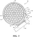
- Figure 1 shows a schematic view of wrappable textile sleeve, referred to hereafter as sleeve 10, constructed in accordance with one aspect of the invention.
- the sleeve 10 has a wrappable elongate wall 12 for routing and protecting elongate members, such as wires or a wire harness 14, for example.
- the elongate wall 12 is constructed from at least one yarn 16 interlaced with itself or a plurality of yarns 16 interlaced with one another.
- the wall 12 is wrapped, also referred to as curled, about a central longitudinal axis 18 to provide an enclosed tubular inner cavity 20.
- the cavity 20 is readily accessible along the longitudinal axis 18 of the sleeve 10 so that the elongate members 14 can be readily disposed radially into the cavity 20, and conversely, removed from the cavity 20, such as during service.
- at least one closure device 22, represented in Figures 1-3 by way of example, in the form of an elongate closure device string member, and represented here as a plurality of string members 22, are preferably attached to the wall 12 during construction of the sleeve 10.
- the string members 22 extend transversely or substantially transversely to the central longitudinal axis 18 so they can be wrapped circumferentially about the wall 12 and subsequently attached to one another, such as by being tied together.
- the sleeve 10 is constructed having at least one closure member 22 integrally attached to the wall 12 to provide a convenient mechanism to maintain the sleeve 10 in its protective configuration about the elongate members 14.
- the wall 12 can be constructed having any suitable size, including length, width, wherein the width directly corresponds to overall diameter of sleeve upon being "cigarette” wrapped, and wall thickness.
- the wall 12 has opposite inner and outer edges 24, 26, respectively, with oppositely facing inner and outer faces 28, 30, respectively, extending between the edges 24, 26.
- the edges 24, 26 extend parallel or substantially parallel to the central axis 18 and terminate at opposite ends 32, 34 of the wall 12.
- the wall 12 can be constructed as a generally flat body that can be subsequently wrapped while maintaining the opposite edges 24, 26 in generally parallel relation with one another and the central axis 18 via an externally applied force, or it can be constructed as a self-wrapping body, as desired.
- the weft, circumferentially extending yarns 16 are provided as heat-settable yarns that are heat-set to retain a curled configuration about the central axis 18 to bias the wall 12 into a self-wrapping tubular configuration.
- the outer side 26 extends beyond and overlaps the inner side 24 to fully enclose the cavity 20 circumferentially, and thus, the wall 12 provides protection against external elements about a full circumference of the wall 12 to the wires 14 contained in the cavity 20.
- the sides 24, 26, when desired, are readily extendable away from one another under an externally applied force to at least partially open and expose the cavity 20.
- the wires 14 can be readily disposed into the cavity 20 during assembly or removed from the cavity 20 during service.
- the sides 24, 26 return automatically under a bias imparted by the heat-set yarns 16 to their relaxed, overlapping self-wrapped position.
- the wall 12 can be constructed from multifilament and/or monofilament yarns, with at least one or more of the yarns 16 in the self-wrapping embodiment being heat-settable.
- one or more of the yarns 16 can be provided as a heat-settable polymeric material, such as polyphenylene sulfide (PPS), for example, which can be heat set at a temperature of about 200-225 degrees Celsius.
- PPS polyphenylene sulfide
- the yarns 16 forming the wall 12 can be interlaced using a variety of processes, such as weaving, knitting, crocheting or braiding, as desired.
- the closure members 22 are integrally attached thereto.
- the closure string members 22 are attached to the wall 12, shown as being attached adjacent the outer edge 26, such that upon wrapping the wall 12 about the elongate members 14, the string members 22 are free to be wrapped circumferentially about the wall 12 with opposite ends 36, 38 of the respective string members 22 being tied together.
- the string members 22 can be provided of any desired length, depending on how may times the string members 22 are to be wrapped about the wall 12, shown here as twice, by way of example and without limitation.
- the string members 22 are attached to the outer face 30 of the wall 12 via a stitched yarn 40.
- the string members 22 are represented as being captured and stitched between a fabric 42 and the outer face 30 of the wall 12, wherein the fabric provides an elongate fastener 43 extending parallel or substantially parallel to the central axis 18, wherein the fastener 43 is represented as being one of a hook or loop portion 43 of a hook and loop type fastener, for example.
- the fastener 43 can be provided as a separate component that is attached to the fabric 42, or the fabric can be provided as the fastener 43.
- the fabric 42 is shown as extending between the opposite ends 32, 34 of the wall 12 adjacent the outer edge 26, and shown as being flush with the outer edge 26.
- the fabric 42, and associated fastener 43 can be provided having any suitable width, such as about 1 ⁇ 2 -1 inch, for example.
- the fabric 12 could be provided as extending less than completely between the ends 32, 34, and further, could be provided as separate segments spaced from one another along the length of the wall 12, if desired.
- the string members 22 are preferably sandwiched between the fabric 42 and the wall 12, and then subsequently the fabric 42 and the string members 22 are fixedly attached to the wall 12 via the stitched yarn 40.
- the number of stitched rows of yam 40 can be fabricated as desired, shown here a two, with one row extending adjacent each longitudinally extending edge of the fabric 42.
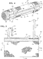
- the sleeve 10 can be readily attached to a support member, also referred to as structure 44 ( Figure 3 ), such as a frame member of an automotive vehicle or aircraft, for example.
- structure 44 a support member of an automotive vehicle or aircraft, for example.
- the other of the hook or loop portion 46 is attached to the structure 44, such as by being preassembled to the frame member during manufacture of the frame member or thereafter.
- the sleeve 10 can be readily attached to the frame member 44 in a quick, economical manner, without having to form openings in the frame member 44 by bringing the first hook or loop fastener 43 on the sleeve 10 into fastening engagement with the other of the second hook or loop fastener 46 on the frame member 44.
- a sleeve 110 constructed in accordance with another aspect of the invention is illustrated, wherein the same reference numerals, offset by a factor of 100, are used as above to identify similar features.
- the sleeve 110 has a wall 112 constructed the same as discussed above. Accordingly, the wall 112 has opposite inner and outer edges 124, 126, respectively, with oppositely facing inner and outer faces 128, 130, respectively, extending between the edges 124, 126.
- the edges 124, 126 extend parallel or substantially parallel to the central axis 118 and terminate at opposite ends 132, 134 of the wall 112.
- At least one, and shown as a pair of closure members 122 are attached to the outer face 130 of the wall 112, such as via a stitched yarn 140.
- the closure members 122 are provided as elongate, flexible straps 122.
- the straps 122 extend between opposite ends 136, 138, where one of the ends 136 is shown as being attached adjacent the outer edge 126. It should be recognized that the straps 122 could be otherwise, such as by being attached at a location between the opposite ends 136, 138, thereby allowing the opposite ends 136, 138 to extend laterally away from the outer side 126.
- end 136 is represented as being captured and stitched between an elongate fastener 143 and the outer face 130 of the wall 112, wherein the fastener 143 is represented as being one of a hook or loop portion 143 of a hook and loop type fastener, for example.
- the straps 122 have opposite inner and outer faces 128', 130', wherein the inner face 128', as best shown in Figure 5 wherein the left strap 122 is twisted to show the inner face 128', is essentially an extension of the inner face 128 of the wall 112, and wherein the outer face 130' is essentially an extension of the outer face 130 of the wall 112.
- the inner face 128' has one of a first hook portion (hp) or loop portion (lp), shown as being adjacent the free end 138.
- the outer face 130' has one of a first loop portion (lp) or hook portion (hp), shown as being adjacent the fixed end 136, wherein the respective first hook portion (hp) and the first loop portion (lp) of each strap 122 are configured for attachment to one another upon the straps 122 being wrapped circumferentially about the wall 112. Accordingly, if the inner face 128' is provided with a hook portion (hp), then the outer face 130 is provided with a loop portion (lp), and vise-versa.
- first hook portion (hp) extends over the full inner face 128' and the first loop portion (lp) extends over the full outer face 130'.
- first loop portion (lp) and hook portion (hp) are fastened together.
- Each closure device 122 is shown as having has a second hook portion (hp') or a second loop portion (lp') on its outer face 130, wherein the second hook portion (hp') or a second loop portion (lp') is configured for attachment to other of the respective hook portion (hp) or loop portion (lp) on the support member 44 (see Figure 3 ).
- the second hook portion (hp') or a second loop portion (lp') is automatically configured facing outwardly for attachment to the support member 44.
- the second hook portion (hp') or second loop portion (lp') can be configured to overlie an elongate fastener 143 extending parallel or substantially parallel to the central axis 118, wherein the fastener 143 is represented as being one of a hook or loop portion 143 of a hook and loop type fastener, for example, as discussed above with regard to the fastener 43.
- the straps 122 wrap over a portion of the fastener 143 with the corresponding hook portion (hp') or loop portion (lp') of the straps 122 being aligned with the fastener 143, the full length of the sleeve 110 is provided with one of the hook or loop portion, as desired, for attachment to the support member 44. Otherwise, if the straps did not include the same hoop or loop portions (hp'), (lp'), then the portion of the fastener 143 having the straps 122 in overlying relation therewith would not provide a source for attachment to the support member 44.
- a sleeve 210 constructed in accordance with another aspect of the invention is illustrated, wherein the same reference numerals, offset by a factor of 200, are used as above to identify similar features.
- the sleeve 210 has a wall 212 constructed the same as discussed above with regard to the wall 12. Accordingly, the wall 212 has opposite inner and outer edges 224, 226, respectively, with oppositely facing inner and outer faces 228, 230, respectively, extending between the edges 224, 226.
- the edges 224, 226 extend parallel or substantially parallel to the central axis 218 and terminate at opposite ends 232, 234 of the wall 212.
- At least one, and shown as a pair of closure members 222 are attached to the outer face 230 of the wall 212, such as via a stitched yarn 240.
- the closure members 222 are provided as elongate, flexible straps, shown here as tie wraps 222.
- the tie wraps 222 extend between opposite ends 236, 238, where one of the ends 238 has a fastening receptacle 48 and the opposite end 236 has fastening teeth 50 configured for locked receipt in the fastening receptacle 48.
- the tie wraps 222 are represented as being captured and stitched between an elongate fastener 243 and the outer face 230 of the wall 212, wherein the fastener 243 is represented as being one of a hook or loop portion 243 of a hook and loop type fastener, as discussed above, by way of example.
- the ends 236, 238 are shown as extending laterally outwardly from the sides 224, 226 of the wall 212 for attachment to one another upon wrapping the wall 212 about the elongate members 14 to be protected.
- the tie wraps 222 extending beneath the fastener 243, the full length of the fastener 243 is exposed for attachment to the fastener 46 on the support member 44.
Landscapes
- Engineering & Computer Science (AREA)
- Architecture (AREA)
- Civil Engineering (AREA)
- Structural Engineering (AREA)
- Mechanical Engineering (AREA)
- Textile Engineering (AREA)
- Details Of Indoor Wiring (AREA)
- Clamps And Clips (AREA)
- Professional, Industrial, Or Sporting Protective Garments (AREA)
- Woven Fabrics (AREA)
Claims (11)
- Manchon tubulaire repliable (10; 110; 210) pour le routage et la protection des éléments allongés (14), comprenant :une paroi allongée (12 ; 112 ; 212) ayant des bords opposés interne et externe (24, 26 ; 124, 126 ; 224, 226) s'étendant parallèlement à un axe longitudinal central (18 ; 118 ; 218) dudit manchon entre des extrémités opposées (32, 34 ; 132, 134 ; 232, 234) dudit manchon et ayant des faces interne et externe (28, 30 ; 128, 130 ; 228, 230) se faisant face de façon opposée et s'étendant entre lesdits bords intérieur et extérieur, ladite face interne délimitant une cavité interne (20) dudit manchon tubulaire lors du repli dudit bord extérieur (26 ; 126 ; 226) en relation de chevauchement extérieur avec ledit bord intérieur (24 ; 124 ; 224) autour dudit axe longitudinal central ; etun élément de fixation allongé (43 ; 143 ; 243) fixée à ladite face externe, ledit élément de fixation s'étendant parallèlement audit axe longitudinal central ;caractérisé en ce que ledit élément de fixation (43 ; 143 ; 243) s'étend sur ladite face externe (30 ; 130 ; 230) de ladite paroi (12 ; 112 ; 212) faisant face vers l'extérieur depuis ladite face externe (30 ; 130 ; 230), et est configurée pour se fixer à un élément de support externe (44) ;
en ce qu'un dispositif de fermeture (22 ; 122 ; 222) est solidaire de ladite paroi (12 ; 112 ; 212), ledit dispositif de fermeture s'étendant transversalement audit élément de fixation (43; 143; 243) et s'étendant circonférentiellement autour de ladite paroi pour fixation à elle-même pour maintenir lesdits bords intérieur et extérieur (24, 26 ; 124, 126 ; 224, 226) en relation de chevauchement ;
et en ce que ledit dispositif de fermeture est capturé entre ladite face externe (30 ; 130 ; 230) et ledit au moins un élément de fixation (43 ; 143 ; 243). - Manchon tubulaire repliable selon la revendication 1, où ledit élément de fixation (43 ; 143 ; 243) est l'une d'une partie crochet ou d'une partie boucle d'un élément de fixation à crochet et boucle.
- Manchon tubulaire repliable selon la revendication 1, dans lequel ledit dispositif de fermeture est une bande (122) ayant une première partie crochet (pc) et une première partie boucle (pb) configurée pour se fixer l'une à l'autre sur ledit dispositif de fermeture (122) étant replié circonférentiellement autour de ladite paroi (112).
- Manchon tubulaire repliable selon la revendication 1, où ladite paroi (12 ; 112 ; 212) est une paroi textile construite à partir d'un fil entrelacé et où ledit élément de fixation allongé (43 ; 143 ; 243) s'étend adjacent audit bord extérieur (26 ; 126 ; 226).
- Manchon tubulaire repliable selon la revendication 4, où ledit élément de fixation (43 ; 143 ; 243) s'étend de façon continue entre lesdites extrémités opposées (32, 34 ; 132, 134 ; 232, 234).
- Manchon tubulaire repliable selon la revendication 4, comprenant en outre un point de suture (40 ; 140 ; 240) attachant ledit élément de fixation (43 ; 143 ; 243) et ledit dispositif de fermeture (22, 122, 222) à ladite face externe (30; 130; 230) de ladite paroi (12; 112; 212).
- Manchon tubulaire repliable selon la revendication 4, où ledit dispositif de fermeture (22) est une chaîne.
- Manchon tubulaire repliable selon la revendication 4, où ledit dispositif de fermeture (122) est une bande ayant une première partie crochet (pc) et une première partie boucle (pb) configurée pour se fixer l'une à l'autre sur ledit dispositif de fermeture étant replié circonférentiellement autour de ladite paroi (112).
- Manchon tubulaire repliable selon la revendication 8, où ledit dispositif de fermeture comporte une seconde partie crochet (pc') ou une seconde partie boucle (pb') configurée pour se fixer à une partie crochet ou une partie boucle sur l'élément de support (44).
- Manchon tubulaire repliable selon la revendication 9, où ladite seconde partie crochet (pc') ou ladite seconde partie boucle (pb') est configurée pour recouvrir l'alignement avec ledit élément de fixation (143).
- Manchon tubulaire repliable selon la revendication 8, où ledit dispositif de fermeture (222) est un collier de serrage ayant une extrémité (238) avec un réceptacle (48) et une autre extrémité (236) avec des dents (50) configurée pour verrouiller la réception par ledit réceptacle.
Applications Claiming Priority (2)
| Application Number | Priority Date | Filing Date | Title |
|---|---|---|---|
| US26439609P | 2009-11-25 | 2009-11-25 | |
| PCT/US2010/057939 WO2011066341A1 (fr) | 2009-11-25 | 2010-11-24 | Manchon textile enroulable doté d'une fixation intégrée et d'un dispositif de fermeture |
Publications (2)
| Publication Number | Publication Date |
|---|---|
| EP2504899A1 EP2504899A1 (fr) | 2012-10-03 |
| EP2504899B1 true EP2504899B1 (fr) | 2017-03-01 |
Family
ID=43533443
Family Applications (1)
| Application Number | Title | Priority Date | Filing Date |
|---|---|---|---|
| EP10784421.9A Active EP2504899B1 (fr) | 2009-11-25 | 2010-11-24 | Manchon textile enroulable doté d'une fixation intégrée et d'un dispositif de fermeture |
Country Status (7)
| Country | Link |
|---|---|
| US (1) | US8367182B2 (fr) |
| EP (1) | EP2504899B1 (fr) |
| JP (1) | JP5623542B2 (fr) |
| CN (1) | CN102656761B (fr) |
| BR (1) | BR112012012274A2 (fr) |
| CA (1) | CA2778167C (fr) |
| WO (1) | WO2011066341A1 (fr) |
Families Citing this family (18)
| Publication number | Priority date | Publication date | Assignee | Title |
|---|---|---|---|---|
| FI8766U1 (fi) * | 2009-10-23 | 2010-06-21 | Pistora Oy | Kaapelinkiinnitysväline |
| JP6085138B2 (ja) * | 2012-10-18 | 2017-02-22 | 矢崎総業株式会社 | 電線保持構造 |
| USD871349S1 (en) * | 2013-01-11 | 2019-12-31 | Harold Kalkstein | Utility sleeve |
| JP2014176108A (ja) * | 2013-03-06 | 2014-09-22 | Sumitomo Wiring Syst Ltd | 弾性部材付き固定テープおよびワイヤハーネス |
| US10358765B2 (en) | 2013-03-11 | 2019-07-23 | Federal-Mogul Powertrain Llc | Wrappable textile sleeve having supplemental lace closure and method of construction thereof |
| US9277684B2 (en) * | 2013-03-13 | 2016-03-01 | Federal-Mogul Powertrain, Inc. | Self-wrapping EMI shielding textile sleeve and method of construction thereof |
| US20160045092A1 (en) * | 2014-08-15 | 2016-02-18 | Paul Iskyan | Removable hose cover system |
| DE102016219374B4 (de) * | 2016-10-06 | 2018-06-14 | Siemens Aktiengesellschaft | Langzeitstabile und stoffschlüssige Strompfadverbindung für Nieder-, Mittelspannungs- und/oder Hochspannungsanlagen bzw. –Schaltgeräte mittels Nanomaterialien |
| CN106786232A (zh) * | 2016-12-08 | 2017-05-31 | 中国北方发动机研究所(天津) | 一种线缆固定防护装置 |
| US10993355B2 (en) * | 2016-12-14 | 2021-04-27 | Federal-Mogul Powertrain Llc | Ground strap and method of grounding a plurality of electrically conductive members therewith |
| US10538866B2 (en) | 2017-02-01 | 2020-01-21 | Federal-Mogul Powertrain Llc | Woven sleeve with integral attachment loops and method of construction thereof |
| US11279505B1 (en) * | 2018-04-04 | 2022-03-22 | Jesse Hinojosa | System for re-securing bales with broken or defective wrapping |
| JP6644824B2 (ja) * | 2018-04-04 | 2020-02-12 | 矢崎総業株式会社 | 分岐回路体及び電線の分岐方法 |
| CA3097107C (fr) * | 2019-10-28 | 2022-04-26 | Donald Groome | Systeme de ventilation pour tuyau isole |
| EP3957695A1 (fr) | 2020-08-17 | 2022-02-23 | tesa SE | Bande adhésive permettant d'envelopper une marchandise allongée telle que, en particulier les faisceaux de câbles et procédé d'enveloppement |
| CN112928709A (zh) * | 2021-01-22 | 2021-06-08 | 广东东南电缆实业有限公司 | 一种电缆用绝缘皮防护结构及其使用方法 |
| DE102021210866A1 (de) | 2021-09-28 | 2023-03-30 | Tesa Se | Klebeband zum Ummanteln von langgestrecktem Gut wie insbesondere Kabelsätzen und Verfahren zur Ummantelung |
| US20230275410A1 (en) * | 2022-02-25 | 2023-08-31 | Velcro Ip Holdings Llc | Support sleeve |
Family Cites Families (18)
| Publication number | Priority date | Publication date | Assignee | Title |
|---|---|---|---|---|
| DE3107557A1 (de) * | 1981-02-27 | 1982-09-16 | Siemens AG, 1000 Berlin und 8000 München | Einrichtung zur befestigung von kabeln und leitungen in gehaeusen |
| US5027862A (en) | 1990-03-15 | 1991-07-02 | Laybourn Bradley K | Hose repair connector apparatus |
| US5273454A (en) | 1990-10-12 | 1993-12-28 | Shotey Michael J | Shroud with ties for inline plug |
| US5147216A (en) | 1990-10-12 | 1992-09-15 | Shotey Michael J | Shroud for in-line electrical plug |
| US5300337A (en) * | 1992-01-09 | 1994-04-05 | The Bentley-Harris Manufacturing Company | Wraparound closure device |
| US5600098A (en) | 1994-07-25 | 1997-02-04 | Kazaks; Alexander | Electronic cable organizer |
| US6111194A (en) | 1997-09-23 | 2000-08-29 | Flex-Cable, Inc. | Electrical and/or fluid power transmitting assembly in a manipulative robot |
| DE10007506B4 (de) | 2000-02-18 | 2006-02-02 | Map Medizin-Technologie Gmbh | Atemgasschlauchanordnung zur Zufuhr eines Atemgases |
| US6384326B1 (en) | 2000-09-05 | 2002-05-07 | Laird Technologies, Inc. | Cable shield closure |
| US6328080B1 (en) * | 2000-09-27 | 2001-12-11 | Federal-Mogul Systems Protection Group, Inc. | Woven sleeve with integral monofilament fasteners |
| US20040099426A1 (en) * | 2002-11-25 | 2004-05-27 | Bohdan Bryl | Flexible cable sleeve |
| US6983767B2 (en) | 2002-11-27 | 2006-01-10 | Action Coupling And Equipment, Inc. | Sleeve for a hose |
| US8127405B2 (en) * | 2003-06-18 | 2012-03-06 | Suburban Machine Co., Inc. | Reusable hose bundling sleeve |
| US7119279B2 (en) * | 2003-11-07 | 2006-10-10 | Zipsleeve, Llc | Protective sleeve |
| DE102004018844B9 (de) * | 2004-04-19 | 2006-06-01 | Polfin Ltd. | Vorrichtung zum Bündeln von Kabelbäumen |
| GB0513136D0 (en) | 2005-06-29 | 2005-08-03 | Icore Internat Ltd | Electrical-cable shielding |
| GB2427746A (en) * | 2005-06-29 | 2007-01-03 | Icore Internat Ltd | Electrical-cable Shielding |
| WO2007063304A1 (fr) | 2005-11-29 | 2007-06-07 | Icore International Limited | Blindage de cable electrique |
-
2010
- 2010-11-24 CN CN201080053294.4A patent/CN102656761B/zh active Active
- 2010-11-24 WO PCT/US2010/057939 patent/WO2011066341A1/fr active Application Filing
- 2010-11-24 US US12/953,788 patent/US8367182B2/en active Active
- 2010-11-24 EP EP10784421.9A patent/EP2504899B1/fr active Active
- 2010-11-24 CA CA2778167A patent/CA2778167C/fr not_active Expired - Fee Related
- 2010-11-24 BR BR112012012274-6A patent/BR112012012274A2/pt not_active Application Discontinuation
- 2010-11-24 JP JP2012541179A patent/JP5623542B2/ja active Active
Non-Patent Citations (1)
| Title |
|---|
| None * |
Also Published As
| Publication number | Publication date |
|---|---|
| CA2778167A1 (fr) | 2011-06-03 |
| BR112012012274A2 (pt) | 2020-11-03 |
| CA2778167C (fr) | 2017-07-04 |
| EP2504899A1 (fr) | 2012-10-03 |
| US20110123759A1 (en) | 2011-05-26 |
| WO2011066341A1 (fr) | 2011-06-03 |
| US8367182B2 (en) | 2013-02-05 |
| JP2013512652A (ja) | 2013-04-11 |
| JP5623542B2 (ja) | 2014-11-12 |
| CN102656761B (zh) | 2015-10-21 |
| CN102656761A (zh) | 2012-09-05 |
Similar Documents
| Publication | Publication Date | Title |
|---|---|---|
| EP2504899B1 (fr) | Manchon textile enroulable doté d'une fixation intégrée et d'un dispositif de fermeture | |
| KR100256773B1 (ko) | 잠금장치를 가지는 랩어라운드 슬리브 | |
| US5178923A (en) | Wraparound closure device | |
| US8663766B2 (en) | Fabric for end fray resistance and protective sleeves formed therewith and methods of construction | |
| EP3108048B1 (fr) | Manchon de tricot pouvant être enroulé sans vrillage et son procédé de construction | |
| US11136710B2 (en) | Wrappable textile sleeve having supplemental lace closure and method of construction thereof | |
| EP3368710B1 (fr) | Manchon textile tressé auto-enroulant ayant une configuration expansée et une configuration contractée, et procédé pour son obtention | |
| EP2904135B1 (fr) | Manchon textile doté d'un fil de trame hybride torsadé et son procédé de construction | |
| US10590575B2 (en) | Braided textile sleeve with self-sustaining expanded and contracted states and enhanced “as supplied” bulk configuration and methods of construction and supplying bulk lengths thereof | |
| JP6415528B2 (ja) | 柔軟性、耐磨耗性織物スリーブおよびその構築方法 | |
| KR20190069454A (ko) | 다수의 공동을 가진 수축가능한 슬리브와 이 슬리브의 제조 방법 | |
| US20220333279A1 (en) | Flexible, Water Repellant, High Temperature Resistant, Wrappable Sleeve and Method of Construction Thereof | |
| CN101622123A (zh) | 带有支撑件的防护套筒总成及其制造方法 | |
| US20040255435A1 (en) | Reusable hose bundling sleeve | |
| WO2023178293A1 (fr) | Manchon textile enroulable à couches multiples souple résistant aux températures élevées, aux fluides et à l'abrasion, et son procédé de construction |
Legal Events
| Date | Code | Title | Description |
|---|---|---|---|
| PUAI | Public reference made under article 153(3) epc to a published international application that has entered the european phase |
Free format text: ORIGINAL CODE: 0009012 |
|
| 17P | Request for examination filed |
Effective date: 20120427 |
|
| AK | Designated contracting states |
Kind code of ref document: A1 Designated state(s): AL AT BE BG CH CY CZ DE DK EE ES FI FR GB GR HR HU IE IS IT LI LT LU LV MC MK MT NL NO PL PT RO RS SE SI SK SM TR |
|
| DAX | Request for extension of the european patent (deleted) | ||
| 17Q | First examination report despatched |
Effective date: 20140617 |
|
| REG | Reference to a national code |
Ref country code: DE Ref legal event code: R079 Ref document number: 602010040427 Country of ref document: DE Free format text: PREVIOUS MAIN CLASS: H02G0003040000 Ipc: H02G0003000000 |
|
| GRAP | Despatch of communication of intention to grant a patent |
Free format text: ORIGINAL CODE: EPIDOSNIGR1 |
|
| RIC1 | Information provided on ipc code assigned before grant |
Ipc: B60R 16/02 20060101ALI20160826BHEP Ipc: H02G 3/34 20060101ALI20160826BHEP Ipc: H02G 3/00 20060101AFI20160826BHEP Ipc: H02G 3/30 20060101ALI20160826BHEP Ipc: H02G 3/04 20060101ALI20160826BHEP |
|
| INTG | Intention to grant announced |
Effective date: 20160912 |
|
| GRAS | Grant fee paid |
Free format text: ORIGINAL CODE: EPIDOSNIGR3 |
|
| GRAJ | Information related to disapproval of communication of intention to grant by the applicant or resumption of examination proceedings by the epo deleted |
Free format text: ORIGINAL CODE: EPIDOSDIGR1 |
|
| GRAL | Information related to payment of fee for publishing/printing deleted |
Free format text: ORIGINAL CODE: EPIDOSDIGR3 |
|
| GRAR | Information related to intention to grant a patent recorded |
Free format text: ORIGINAL CODE: EPIDOSNIGR71 |
|
| GRAA | (expected) grant |
Free format text: ORIGINAL CODE: 0009210 |
|
| INTC | Intention to grant announced (deleted) | ||
| INTG | Intention to grant announced |
Effective date: 20170119 |
|
| AK | Designated contracting states |
Kind code of ref document: B1 Designated state(s): AL AT BE BG CH CY CZ DE DK EE ES FI FR GB GR HR HU IE IS IT LI LT LU LV MC MK MT NL NO PL PT RO RS SE SI SK SM TR |
|
| REG | Reference to a national code |
Ref country code: GB Ref legal event code: FG4D |
|
| REG | Reference to a national code |
Ref country code: CH Ref legal event code: EP Ref country code: AT Ref legal event code: REF Ref document number: 872350 Country of ref document: AT Kind code of ref document: T Effective date: 20170315 |
|
| REG | Reference to a national code |
Ref country code: IE Ref legal event code: FG4D |
|
| REG | Reference to a national code |
Ref country code: DE Ref legal event code: R096 Ref document number: 602010040427 Country of ref document: DE |
|
| REG | Reference to a national code |
Ref country code: NL Ref legal event code: MP Effective date: 20170301 |
|
| REG | Reference to a national code |
Ref country code: LT Ref legal event code: MG4D |
|
| REG | Reference to a national code |
Ref country code: AT Ref legal event code: MK05 Ref document number: 872350 Country of ref document: AT Kind code of ref document: T Effective date: 20170301 |
|
| PG25 | Lapsed in a contracting state [announced via postgrant information from national office to epo] |
Ref country code: FI Free format text: LAPSE BECAUSE OF FAILURE TO SUBMIT A TRANSLATION OF THE DESCRIPTION OR TO PAY THE FEE WITHIN THE PRESCRIBED TIME-LIMIT Effective date: 20170301 Ref country code: GR Free format text: LAPSE BECAUSE OF FAILURE TO SUBMIT A TRANSLATION OF THE DESCRIPTION OR TO PAY THE FEE WITHIN THE PRESCRIBED TIME-LIMIT Effective date: 20170602 Ref country code: LT Free format text: LAPSE BECAUSE OF FAILURE TO SUBMIT A TRANSLATION OF THE DESCRIPTION OR TO PAY THE FEE WITHIN THE PRESCRIBED TIME-LIMIT Effective date: 20170301 Ref country code: HR Free format text: LAPSE BECAUSE OF FAILURE TO SUBMIT A TRANSLATION OF THE DESCRIPTION OR TO PAY THE FEE WITHIN THE PRESCRIBED TIME-LIMIT Effective date: 20170301 Ref country code: NO Free format text: LAPSE BECAUSE OF FAILURE TO SUBMIT A TRANSLATION OF THE DESCRIPTION OR TO PAY THE FEE WITHIN THE PRESCRIBED TIME-LIMIT Effective date: 20170601 |
|
| PG25 | Lapsed in a contracting state [announced via postgrant information from national office to epo] |
Ref country code: LV Free format text: LAPSE BECAUSE OF FAILURE TO SUBMIT A TRANSLATION OF THE DESCRIPTION OR TO PAY THE FEE WITHIN THE PRESCRIBED TIME-LIMIT Effective date: 20170301 Ref country code: ES Free format text: LAPSE BECAUSE OF FAILURE TO SUBMIT A TRANSLATION OF THE DESCRIPTION OR TO PAY THE FEE WITHIN THE PRESCRIBED TIME-LIMIT Effective date: 20170301 Ref country code: BG Free format text: LAPSE BECAUSE OF FAILURE TO SUBMIT A TRANSLATION OF THE DESCRIPTION OR TO PAY THE FEE WITHIN THE PRESCRIBED TIME-LIMIT Effective date: 20170601 Ref country code: RS Free format text: LAPSE BECAUSE OF FAILURE TO SUBMIT A TRANSLATION OF THE DESCRIPTION OR TO PAY THE FEE WITHIN THE PRESCRIBED TIME-LIMIT Effective date: 20170301 Ref country code: AT Free format text: LAPSE BECAUSE OF FAILURE TO SUBMIT A TRANSLATION OF THE DESCRIPTION OR TO PAY THE FEE WITHIN THE PRESCRIBED TIME-LIMIT Effective date: 20170301 Ref country code: SE Free format text: LAPSE BECAUSE OF FAILURE TO SUBMIT A TRANSLATION OF THE DESCRIPTION OR TO PAY THE FEE WITHIN THE PRESCRIBED TIME-LIMIT Effective date: 20170301 |
|
| PG25 | Lapsed in a contracting state [announced via postgrant information from national office to epo] |
Ref country code: NL Free format text: LAPSE BECAUSE OF FAILURE TO SUBMIT A TRANSLATION OF THE DESCRIPTION OR TO PAY THE FEE WITHIN THE PRESCRIBED TIME-LIMIT Effective date: 20170301 |
|
| REG | Reference to a national code |
Ref country code: FR Ref legal event code: PLFP Year of fee payment: 8 |
|
| PG25 | Lapsed in a contracting state [announced via postgrant information from national office to epo] |
Ref country code: CZ Free format text: LAPSE BECAUSE OF FAILURE TO SUBMIT A TRANSLATION OF THE DESCRIPTION OR TO PAY THE FEE WITHIN THE PRESCRIBED TIME-LIMIT Effective date: 20170301 Ref country code: RO Free format text: LAPSE BECAUSE OF FAILURE TO SUBMIT A TRANSLATION OF THE DESCRIPTION OR TO PAY THE FEE WITHIN THE PRESCRIBED TIME-LIMIT Effective date: 20170301 Ref country code: SK Free format text: LAPSE BECAUSE OF FAILURE TO SUBMIT A TRANSLATION OF THE DESCRIPTION OR TO PAY THE FEE WITHIN THE PRESCRIBED TIME-LIMIT Effective date: 20170301 Ref country code: EE Free format text: LAPSE BECAUSE OF FAILURE TO SUBMIT A TRANSLATION OF THE DESCRIPTION OR TO PAY THE FEE WITHIN THE PRESCRIBED TIME-LIMIT Effective date: 20170301 |
|
| PG25 | Lapsed in a contracting state [announced via postgrant information from national office to epo] |
Ref country code: SM Free format text: LAPSE BECAUSE OF FAILURE TO SUBMIT A TRANSLATION OF THE DESCRIPTION OR TO PAY THE FEE WITHIN THE PRESCRIBED TIME-LIMIT Effective date: 20170301 Ref country code: PL Free format text: LAPSE BECAUSE OF FAILURE TO SUBMIT A TRANSLATION OF THE DESCRIPTION OR TO PAY THE FEE WITHIN THE PRESCRIBED TIME-LIMIT Effective date: 20170301 Ref country code: PT Free format text: LAPSE BECAUSE OF FAILURE TO SUBMIT A TRANSLATION OF THE DESCRIPTION OR TO PAY THE FEE WITHIN THE PRESCRIBED TIME-LIMIT Effective date: 20170703 Ref country code: IS Free format text: LAPSE BECAUSE OF FAILURE TO SUBMIT A TRANSLATION OF THE DESCRIPTION OR TO PAY THE FEE WITHIN THE PRESCRIBED TIME-LIMIT Effective date: 20170701 |
|
| REG | Reference to a national code |
Ref country code: DE Ref legal event code: R097 Ref document number: 602010040427 Country of ref document: DE |
|
| PLBE | No opposition filed within time limit |
Free format text: ORIGINAL CODE: 0009261 |
|
| STAA | Information on the status of an ep patent application or granted ep patent |
Free format text: STATUS: NO OPPOSITION FILED WITHIN TIME LIMIT |
|
| PG25 | Lapsed in a contracting state [announced via postgrant information from national office to epo] |
Ref country code: DK Free format text: LAPSE BECAUSE OF FAILURE TO SUBMIT A TRANSLATION OF THE DESCRIPTION OR TO PAY THE FEE WITHIN THE PRESCRIBED TIME-LIMIT Effective date: 20170301 |
|
| 26N | No opposition filed |
Effective date: 20171204 |
|
| PG25 | Lapsed in a contracting state [announced via postgrant information from national office to epo] |
Ref country code: SI Free format text: LAPSE BECAUSE OF FAILURE TO SUBMIT A TRANSLATION OF THE DESCRIPTION OR TO PAY THE FEE WITHIN THE PRESCRIBED TIME-LIMIT Effective date: 20170301 |
|
| PG25 | Lapsed in a contracting state [announced via postgrant information from national office to epo] |
Ref country code: MC Free format text: LAPSE BECAUSE OF FAILURE TO SUBMIT A TRANSLATION OF THE DESCRIPTION OR TO PAY THE FEE WITHIN THE PRESCRIBED TIME-LIMIT Effective date: 20170301 |
|
| GBPC | Gb: european patent ceased through non-payment of renewal fee |
Effective date: 20171124 |
|
| PG25 | Lapsed in a contracting state [announced via postgrant information from national office to epo] |
Ref country code: LI Free format text: LAPSE BECAUSE OF NON-PAYMENT OF DUE FEES Effective date: 20171130 Ref country code: CH Free format text: LAPSE BECAUSE OF NON-PAYMENT OF DUE FEES Effective date: 20171130 |
|
| PG25 | Lapsed in a contracting state [announced via postgrant information from national office to epo] |
Ref country code: LU Free format text: LAPSE BECAUSE OF NON-PAYMENT OF DUE FEES Effective date: 20171124 |
|
| REG | Reference to a national code |
Ref country code: BE Ref legal event code: MM Effective date: 20171130 |
|
| REG | Reference to a national code |
Ref country code: IE Ref legal event code: MM4A |
|
| PG25 | Lapsed in a contracting state [announced via postgrant information from national office to epo] |
Ref country code: MT Free format text: LAPSE BECAUSE OF NON-PAYMENT OF DUE FEES Effective date: 20171124 |
|
| REG | Reference to a national code |
Ref country code: FR Ref legal event code: PLFP Year of fee payment: 9 |
|
| PG25 | Lapsed in a contracting state [announced via postgrant information from national office to epo] |
Ref country code: IE Free format text: LAPSE BECAUSE OF NON-PAYMENT OF DUE FEES Effective date: 20171124 |
|
| PG25 | Lapsed in a contracting state [announced via postgrant information from national office to epo] |
Ref country code: GB Free format text: LAPSE BECAUSE OF NON-PAYMENT OF DUE FEES Effective date: 20171124 Ref country code: BE Free format text: LAPSE BECAUSE OF NON-PAYMENT OF DUE FEES Effective date: 20171130 |
|
| PGFP | Annual fee paid to national office [announced via postgrant information from national office to epo] |
Ref country code: IT Payment date: 20181121 Year of fee payment: 12 |
|
| PG25 | Lapsed in a contracting state [announced via postgrant information from national office to epo] |
Ref country code: HU Free format text: LAPSE BECAUSE OF FAILURE TO SUBMIT A TRANSLATION OF THE DESCRIPTION OR TO PAY THE FEE WITHIN THE PRESCRIBED TIME-LIMIT; INVALID AB INITIO Effective date: 20101124 |
|
| PG25 | Lapsed in a contracting state [announced via postgrant information from national office to epo] |
Ref country code: CY Free format text: LAPSE BECAUSE OF NON-PAYMENT OF DUE FEES Effective date: 20170301 |
|
| PG25 | Lapsed in a contracting state [announced via postgrant information from national office to epo] |
Ref country code: MK Free format text: LAPSE BECAUSE OF FAILURE TO SUBMIT A TRANSLATION OF THE DESCRIPTION OR TO PAY THE FEE WITHIN THE PRESCRIBED TIME-LIMIT Effective date: 20170301 |
|
| PG25 | Lapsed in a contracting state [announced via postgrant information from national office to epo] |
Ref country code: TR Free format text: LAPSE BECAUSE OF FAILURE TO SUBMIT A TRANSLATION OF THE DESCRIPTION OR TO PAY THE FEE WITHIN THE PRESCRIBED TIME-LIMIT Effective date: 20170301 |
|
| PG25 | Lapsed in a contracting state [announced via postgrant information from national office to epo] |
Ref country code: AL Free format text: LAPSE BECAUSE OF FAILURE TO SUBMIT A TRANSLATION OF THE DESCRIPTION OR TO PAY THE FEE WITHIN THE PRESCRIBED TIME-LIMIT Effective date: 20170301 |
|
| PG25 | Lapsed in a contracting state [announced via postgrant information from national office to epo] |
Ref country code: IT Free format text: LAPSE BECAUSE OF NON-PAYMENT OF DUE FEES Effective date: 20191124 |
|
| P01 | Opt-out of the competence of the unified patent court (upc) registered |
Effective date: 20230528 |
|
| PGFP | Annual fee paid to national office [announced via postgrant information from national office to epo] |
Ref country code: FR Payment date: 20231019 Year of fee payment: 14 Ref country code: DE Payment date: 20231019 Year of fee payment: 14 |