EP2503525B1 - Housing with anti-mounting catch on contact - Google Patents
Housing with anti-mounting catch on contact Download PDFInfo
- Publication number
- EP2503525B1 EP2503525B1 EP12161069.5A EP12161069A EP2503525B1 EP 2503525 B1 EP2503525 B1 EP 2503525B1 EP 12161069 A EP12161069 A EP 12161069A EP 2503525 B1 EP2503525 B1 EP 2503525B1
- Authority
- EP
- European Patent Office
- Prior art keywords
- base
- electrical contact
- chamber
- box
- contact member
- Prior art date
- Legal status (The legal status is an assumption and is not a legal conclusion. Google has not performed a legal analysis and makes no representation as to the accuracy of the status listed.)
- Active
Links
Images


Classifications
-
- G—PHYSICS
- G08—SIGNALLING
- G08B—SIGNALLING SYSTEMS, e.g. PERSONAL CALLING SYSTEMS; ORDER TELEGRAPHS; ALARM SYSTEMS
- G08B17/00—Fire alarms; Alarms responsive to explosion
- G08B17/10—Actuation by presence of smoke or gases, e.g. automatic alarm devices for analysing flowing fluid materials by the use of optical means
- G08B17/11—Actuation by presence of smoke or gases, e.g. automatic alarm devices for analysing flowing fluid materials by the use of optical means using an ionisation chamber for detecting smoke or gas
- G08B17/113—Constructional details
Definitions
- the present invention relates to the field of housings comprising a base and a box that can be mounted on this base and containing an electrical or electronic device and an electric battery for powering the latter as disclosed for example document WO 2004/082042 .
- the box has, in one piece, an elastic arm adapted to cooperate with a sidewall of the body of the electric battery, this arm having a portion abutting against a stop of the base to prevent mounting of the box on the base when the battery is missing and allowing this mounting when the battery is present.
- the present invention aims to provide an improvement to the currently known housings and used.
- an alarm box that includes a base and a box adapted to be mounted on the base and to be separated.
- the box may be provided with at least one elastic electrical contact member and have a compartment that can receive an electric battery in a contact position in which an electrical contact pad of this electric battery is in contact with said elastic electrical contact member said electrical contact member resiliently deforming in one direction toward said electrical contact position upon placement and in the other direction upon removal of the stack to a free position.
- the base and the box may comprise means enabling them to pivot relative to each other between a so-called engagement position in which the box and the base are coupled, that the battery is absent or present in the compartment (16), and a so-called mounted position, operational state.
- the base and the box may be provided respectively with anti-assembly means that can occupy with respect to each other an anti-assembly position in which they cooperate and oppose the displacement of the box relative to the base between the engagement and mounting positions and a release position in which the base and the box can be brought to said mounted position from said engagement position and vice versa.
- the anti-assembly means of the box may be integral with said elastic electrical contact member and be movable between said anti-assembly position and said release position under the effect of the deformation of this resilient electrical contact member between said free position and said electrical contact position.
- the anti-assembly means also constitutes a means of detecting the presence / absence of the electric battery.
- the box and the base can be rotatably mounted relative to one another to said mounting position.
- the anti-assembly means of the base may comprise a stop and the anti-assembly means of the box may comprise an anti-assembly finger connected to the elastic electrical contact member.
- the anti-assembly finger and the electrical contact member may be formed of a single metal part.
- the base and a box may comprise plates facing each other and able to pivot on one another, the plate of the base having an opening in which is arranged said stop and the plate the box having an opening through which passes said anti-assembly finger which is engaged in said opening of the plate of the base.
- the opening of the box plate may have opposite flanks along which said anti-blocking finger moves at short distances.
- the compartment of the box can be opened on the side of the base.
- the electric battery may comprise two electrical contact pads of different sections which are engaged in openings of a wall of the housing, these openings corresponding to the section of these electrical contact pads.
- the anti-assembly means of the box may comprise a slide movable under the effect of the elastic deformation of the resilient electrical contact member.
- Said elastic electrical contact member can be mounted cantilever on an electronic card mounted in the box.
- a housing 1 shown in the figures comprises a base 2 and a box 3 adapted to be mounted on the base and to be separated.
- the base 2 and the box 3 are for example a plastic material.
- the base is intended to be fixed to a ceiling and the box is intended to be hooked to the base, from below. Nevertheless, this provision, intended to facilitate the understanding of the description which follows, is not limiting.
- the base 2 comprises a circular plate 4 and, at the periphery of this plate, an upper annular flange 5 projecting upwards and a lower annular flange 6 projecting downwards.
- the plate 4 has different openings 7 adapted for fixing it with screws and a large opening 8.
- the casing 3 is generally cylindrical in shape and comprises a rear or upper circular plate 9, a peripheral wall 9a and a front cover 9b.
- the box 3 has a recessed annular wall 10 facing downwards, discontinuous peripherally, and an upper annular flange 11 facing upwards and in the extension of the peripheral wall 9a, which determine between they have an annular groove 12 facing upwards.
- the circular plate 9 of the box 3 is intended to bear against the circular plate 4 of the base 2, the lower annular flange 6 of the base 2 then being engaged in the annular groove 12 of the box 3, so that the base 2 and the box 3, in the support position, can rotate relative to each other being guided.
- the lower annular flange 6 of the base 2 and the casing 3, inside its annular groove 12, have pairs of stops 13 and 14, distributed peripherally, such that, in said support position, the base 2 and the box 3 may be rotated relative to each other between an engagement position and a mounted position.
- the lower annular flange 6 of the base 2 has inner hooks 15 distributed peripherally, able to engage below portions of the wall annular 10 of the box 3 when, in said support position, the base 2 and the box 3 leave said engagement position, towards said mounted position, so as to maintain relative to each other the box 3 on the base 2 to said mounted position, a bayonet mount being thus realized.
- the box 3 has a compartment 16 arranged through its upper circular plate 9, this compartment 16 being open upwards, on the side of the base 2.
- the compartment 16 is for example of parallelepipedal shape and has a bottom 17, longitudinal walls 18 and 19, a rear wall 20 and a front wall 21. According to the example shown, the longitudinal axis of the compartment 16 is slightly offset relative to in the center of the upper circular plate 9 of the box 3 and the front wall 21 is in the peripheral zone of the upper circular plate 9.
- the compartment 16 is intended to receive an electric battery 22, for example of parallelepipedal shape, slightly wedged laterally, in a flat position such that its pads projecting electrical connection 23 and 24 are on the side of the front wall 21 and are engaged, with low lateral play, through passages 25 and 26 of this front wall 21, the pads projecting electrical connection 23 and 24 and the passages 25 and 26 being offset parallel to the bottom 17 and the upper circular plate 9.
- the rear wall 20 is adapted to facilitate the installation and removal of the battery 22.
- the electrical connection pads 23 and 24 of the battery 22 are of different cross-sections and the passages 25 and 26 are formed by vertical slots of corresponding different widths, so that the electric battery 22 can not be installed in the compartment 16 only in a unique position.
- the box 3 is internally provided, under its upper circular plate 9, resilient electrical contact members 27 and 28, in the form of slightly arcuate blades, which are fixed, cantilevered, on an electronic card 29 extending below the bottom 17 of the compartment 16 and beyond of the last.
- These elastic electrical contact members 27 and 28 extend upwards, outside the front wall 21 of the compartment 16, and are able to be elastically in contact with the electrical connection pads 23 and 24 of the battery 22. .
- the elastic electrical contact members 27 and 28 are in a free position.
- the electrical contact pads 23 and 24 of the electric battery 22 come into contact with the elastic electrical contact members 27 and 28, on their curved zones, and the are pushed towards the periphery of the box 3.
- the resilient electrical contact members 27 and 28 deform elastically by flexing to a position of final contact illustrated in FIGS. Figures 7 and 8 .
- the elastic electrical contact members 27 and 28 are deformed in the other direction, from their final contact position to their free position.
- the elastic electrical contact members 27 and 28 are provided on their upper free end with anti-assembly fingers 30 and 31 which extend upwards and which pass through openings 32 and 33 arranged through the circular plate. upper 9 of the housing 3, anti-assembly fingers 30 and 31 going upwards beyond this upper circular plate 9.
- the elastic electrical contact members 27 and 28 and the fingers anti-assembly 30 and 31 are respectively one piece metal.
- the elastic electrical contact members 27 and 28 are placed in such a way that the anti-assembly fingers 30 and 31 are angularly offset with respect to the upper annular plate 9 of the box 3 and that they thus move substantially radially at the same time.
- upper circular plate 9 of the box 3 between an anti-assembly position when the electric battery 22 is absent ( figures 1 and 5 ) and a release position when the battery is installed in compartment 16 ( figures 7 and 12 ).
- the openings 32 and 33 of the upper circular plate 9 of the box 3 have opposite flanks along which the anti-assembly fingers 30 and 31 move at short distances.
- the circular plate 4 of the base 2 has an opening 34 whose portions of its edges form abutments 35 and 36 which are localized in the following manner.
- the anti-assembly fingers 30 and 31 extend through the opening 34.
- the anti-assembly fingers 30 and 31, placed in said anti-assembly position are adjacent to these stops 35 and 36 and prevent the rotation of the box 3 relative to the base 2 towards said mounted position.
- the anti-assembly fingers 30 and 31, placed in said release position are disengaged with respect to the stops 35 and 36 and are free in the opening 34, such that the base 2 and the caisson 3 can be pivoted relative to one another between said engagement position ( figure 8 ) and said mounted position ( figure 11 ), one way or the other.
- the housing 1 which has just been described can be used in the following manner.
- the anti-assembly fingers 30 and 31 are opposite stops 35 and 36 ( figures 6 and 9 ), in said anti-assembly position. Any attempt to rotate the box 3 relative to the base 2 to said mounting position is prohibited.
- an electric battery 22 is installed in the compartment 16 ( figures 7 and 12 ).
- the anti-assembly fingers 30 and 31 pass from said anti-assembly position to said release position under the effect of the deformation and displacement of the elastic electrical contact members 27 and 28. It can be seen that especially between figure 1 illustrating the anti-assembly position and the figure 12 illustrating the release position, the anti-assembly fingers 30 and 31 moved away from the compartment 16 by sliding in the passages 32 and 33.
- the housing 1 is then operational where the base has been previously fixed.
- the elastic deformable electrical contact members 27 and 28 and the movable fingers 30 and 31 which they carry constitute not only a mechanical means of detecting the absence or the presence of the electric cell 22 in the compartment 16 of the box 3 by the fact that the box 3 can be fixedly mounted or not fixedly mounted on the base 2 to said mounted position, but also an electrical means for detecting the absence or presence of the electric battery 22 by the fact that the elastic electrical contact members 27 and 28 are in contact or are not in contact with the electrical contact pads 23 and 24 of the electric battery 22, which is detectable by the electrical circuits of the electronic card 29 included in the box 3.
- the annular plate 4 of the base 2 may comprise at least one protector pin 37 projecting upwards, located in the vicinity of the anti-assembly fingers 27 and 28 and protruding upwards relative thereto. If the housing 1 is placed on an electrically conductive surface, on the side of the base 2, then this protection pin 37 bears on this surface and the anti-assembly fingers 27 and 28 remain at a distance from this surface to avoid a short circuit between the electrical contact pads 23 and 24 of the battery 22. In addition, the protection pin 37 protects the fingers 30 and 31 against crushing.
- a single anti-assembly finger 30 or 31 could be sufficient to prevent rotation of the box 3 relative to the base 2.
- the elastic electrical contact members 27 and 28 could be connected to one or sliders mounted on the box and movable under the effect of the elastic deformation of these bodies between positions corresponding to said positions of anti- mounting and release anti-assembly fingers 30 and 31.
- the housing 3 may be intended to contain in particular a smoke detector. Nevertheless, the mechanical and electrical means for detecting the presence and absence of an electric battery 22 described could be used in housings intended for all other uses, in particular in the field of alarm systems.
Landscapes
- Chemical & Material Sciences (AREA)
- Analytical Chemistry (AREA)
- Business, Economics & Management (AREA)
- Emergency Management (AREA)
- Physics & Mathematics (AREA)
- General Physics & Mathematics (AREA)
- Battery Mounting, Suspending (AREA)
Description
La présente invention concerne le domaine des boîtiers comprenant un socle et un caisson pouvant être monté sur ce socle et contenant un dispositif électrique ou électronique et une pile électrique pour l'alimentation de ce dernier comme le divulgue par example le document
Dans des boîtiers d'alarme connus, tels que des détecteurs de fumée, le caisson présente, d'une seule pièce, un bras élastique apte à coopérer avec un flanc du corps de la pile électrique, ce bras présentant une partie venant en butée contre une butée du socle pour empêcher le montage du caisson sur le socle lorsque la pile électrique est absente et autorisant ce montage lorsque la pile électrique est présente.In known alarm boxes, such as smoke detectors, the box has, in one piece, an elastic arm adapted to cooperate with a sidewall of the body of the electric battery, this arm having a portion abutting against a stop of the base to prevent mounting of the box on the base when the battery is missing and allowing this mounting when the battery is present.
La présente invention a pour but de proposer un perfectionnement aux boîtiers actuellement connus et utilisés.The present invention aims to provide an improvement to the currently known housings and used.
Il est proposé un boîtier d'alarme qui comprend un socle et un caisson apte à être monté sur le socle et à en être séparé.It is proposed an alarm box that includes a base and a box adapted to be mounted on the base and to be separated.
Le caisson peut être muni d'au moins un organe élastique de contact électrique et présenter un compartiment pouvant recevoir une pile électrique dans une position de contact dans laquelle un plot de contact électrique de cette pile électrique est en contact avec ledit organe élastique de contact électrique, ledit organe de contact électrique se déformant élastiquement dans un sens vers ladite position de contact électrique lors de la mise en place et dans l'autre sens lors de l'enlèvement de la pile vers une position libre.The box may be provided with at least one elastic electrical contact member and have a compartment that can receive an electric battery in a contact position in which an electrical contact pad of this electric battery is in contact with said elastic electrical contact member said electrical contact member resiliently deforming in one direction toward said electrical contact position upon placement and in the other direction upon removal of the stack to a free position.
Le socle et le caisson peuvent comprendre des moyens leur permettant de pivoter l'un par rapport à l'autre entre une position dite d'engagement dans laquelle le caisson et le socle sont accouplés, que la pile soit absente ou présente dans le compartiment (16), et une position dite montée, d'état opérationnel.The base and the box may comprise means enabling them to pivot relative to each other between a so-called engagement position in which the box and the base are coupled, that the battery is absent or present in the compartment (16), and a so-called mounted position, operational state.
Le socle et le caisson peuvent être munis respectivement de moyens d'anti-montage pouvant occuper l'un par rapport à l'autre une position d'anti-montage dans laquelle ils coopèrent et s'opposent au déplacement du caisson par rapport au socle entre les positions d'engagement et montée et une position de libération dans laquelle le socle et le caisson peuvent être amenés jusqu'à ladite position montée depuis ladite position d'engagement et réciproquement.The base and the box may be provided respectively with anti-assembly means that can occupy with respect to each other an anti-assembly position in which they cooperate and oppose the displacement of the box relative to the base between the engagement and mounting positions and a release position in which the base and the box can be brought to said mounted position from said engagement position and vice versa.
Le moyen d'anti-montage du caisson peut être solidaire dudit organe élastique de contact électrique et être déplaçable entre ladite position d'anti-montage et ladite position de libération sous l'effet de la déformation de cet organe élastique de contact électrique entre ladite position libre et ladite position de contact électrique.The anti-assembly means of the box may be integral with said elastic electrical contact member and be movable between said anti-assembly position and said release position under the effect of the deformation of this resilient electrical contact member between said free position and said electrical contact position.
Ainsi, le moyen d'anti-montage constitue en outre un moyen de détection de présence/absence de la pile électrique.Thus, the anti-assembly means also constitutes a means of detecting the presence / absence of the electric battery.
Le caisson et le socle peuvent être montés par rotation de l'un par rapport à l'autre jusqu'à ladite position de montage.The box and the base can be rotatably mounted relative to one another to said mounting position.
Le moyen d'anti-montage du socle peut comprendre une butée et le moyen d'anti-montage du caisson peut comprendre un doigt d'anti-montage relié à l'organe élastique de contact électrique.The anti-assembly means of the base may comprise a stop and the anti-assembly means of the box may comprise an anti-assembly finger connected to the elastic electrical contact member.
Le doigt d'anti-montage et l'organe de contact électrique peuvent être formés d'une seule pièce métallique.The anti-assembly finger and the electrical contact member may be formed of a single metal part.
Le socle et un caisson peuvent comprendre des plaques en vis-à-vis l'une de l'autre et aptes à pivoter l'une sur l'autre, la plaque du socle présentant une ouverture dans laquelle est aménagée ladite butée et la plaque du caisson présentant une ouverture au travers de laquelle passe ledit doigt d'anti-montage qui est engagé dans ladite ouverture de la plaque du socle.The base and a box may comprise plates facing each other and able to pivot on one another, the plate of the base having an opening in which is arranged said stop and the plate the box having an opening through which passes said anti-assembly finger which is engaged in said opening of the plate of the base.
L'ouverture de la plaque du caisson peut présenter des flancs opposés le long desquels ledit doigt d'anti-blocage se déplace à faibles distances.The opening of the box plate may have opposite flanks along which said anti-blocking finger moves at short distances.
Le compartiment du caisson peut être ouvert du côté du socle.The compartment of the box can be opened on the side of the base.
La pile électrique peut comprendre deux plots de contact électrique de sections différentes qui sont engagés dans des ouvertures d'une paroi du boîtier, ces ouvertures correspondant à la section de ces plots de contact électrique.The electric battery may comprise two electrical contact pads of different sections which are engaged in openings of a wall of the housing, these openings corresponding to the section of these electrical contact pads.
Le moyen d'anti-montage du caisson peut comprendre un coulisseau déplaçable sous l'effet de la déformation élastique de l'organe élastique de contact électrique.The anti-assembly means of the box may comprise a slide movable under the effect of the elastic deformation of the resilient electrical contact member.
Ledit organe élastique de contact électrique peut être monté en porte-à-faux sur une carte électronique montée dans le caisson.Said elastic electrical contact member can be mounted cantilever on an electronic card mounted in the box.
Un boîtier selon la présente invention va maintenant être décrit à titre d'exemple non limitatif, illustré par le dessin annexé dans lequel :
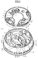
- la
figure 1 représente une vue en perspective du boîtier, comprenant un socle et un caisson séparés, sans pile électrique ; - la
figure 2 représente une vue en perspective, partiellement en coupe verticale, du boîtier, le socle et le caisson étant accouplés ; - la
figure 3 représente une coupe horizontale en vue de dessus du caisson, au travers d'un compartiment muni d'une pile électrique, selon III-III de lafigure 4 ; - la
figure 4 représente une coupe verticale du caisson, transversalement aux plots de contact électrique de la pile, selon IV-IV de lafigure 3 ; - la
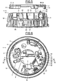
figure 5 représente une coupe verticale du boîtier longitudinalement au compartiment du caisson, le socle et le caisson étant séparés et la pile électrique étant absente, selon V-V de lafigure 6 ; - la
figure 6 représente une vue de dessus du boîtier, le socle et le caisson étant accouplés et la pile électrique étant absente ; - la
figure 7 représente une coupe verticale du boîtier longitudinalement au compartiment du caisson, le socle et le caisson étant séparés et la pile électrique étant présente, selon VII-VII de lafigure 8 ; - la
figure 8 représente une vue de dessus du boîtier, le socle et le caisson étant accouplés et la pile électrique étant présente ; - la
figure 9 représente une coupe verticale correspondant à celle de lafigure 5 , le socle et le caisson étant accouplés et la pile électrique étant absente, selon IX-IX de lafigure 6 ; - la
figure 10 représente une coupe verticale correspondant à celle de lafigure 7 , le socle et le caisson étant accouplés et la pile électrique étant présente, selon X-X de lafigure 8 ; - la
figure 11 représente une vue de dessus du boîtier, le socle et le caisson étant accouplés en position finale de montage et la pile électrique étant présente ; - et la
figure 12 représente une vue en perspective correspondant à celle de lafigure 1 , la pile électrique étant présente.
- the
figure 1 represents a perspective view of the housing, comprising a base and a separate box, without an electric battery; - the
figure 2 is a perspective view, partially in vertical section, of the housing, the base and the housing being coupled; - the
figure 3 represents a horizontal section in plan view of the box, through a compartment provided with an electric battery, according to III-III of thefigure 4 ; - the
figure 4 represents a vertical section of the box, transversely to the electrical contact pads of the cell, according to IV-IV of thefigure 3 ; - the
figure 5 represents a vertical section of the housing longitudinally to the compartment of the box, the base and the box being separated and the electric battery being absent, according to VV of thefigure 6 ; - the
figure 6 represents a view from above of the case, the base and the box being coupled and the electric battery being absent; - the
figure 7 represents a vertical section of the housing longitudinally to the compartment of the box, the base and the box being separated and the electric battery being present, according to VII-VII of thefigure 8 ; - the
figure 8 represents a view from above of the housing, the base and the box being coupled and the electric battery being present; - the
figure 9 represents a vertical section corresponding to that of thefigure 5 , the base and the box being coupled and the electric battery being absent, according to IX-IX of thefigure 6 ; - the
figure 10 represents a vertical section corresponding to that of thefigure 7 , the base and the box being coupled and the electric battery being present, according to XX of thefigure 8 ; - the
figure 11 represents a top view of the housing, the base and the housing being coupled in the final mounting position and the electric battery being present; - and the
figure 12 represents a perspective view corresponding to that of thefigure 1 , the electric battery being present.
Un boîtier 1 représenté sur les figures comprend un socle 2 et un caisson 3 apte à être monté sur le socle et à en être séparé. Le socle 2 et le caisson 3 sont par exemple en une matière plastique.A
Par exemple, le socle est destiné à être fixé à un plafond et le caisson est destiné à être accroché au socle, par le dessous. Néanmoins, cette disposition, destinée à faciliter la compréhension de la description qui suit, n'est pas limitative.For example, the base is intended to be fixed to a ceiling and the box is intended to be hooked to the base, from below. Nevertheless, this provision, intended to facilitate the understanding of the description which follows, is not limiting.
Comme illustré notamment sur les
Le caisson 3 est de forme générale cylindrique et comprend une plaque circulaire arrière ou supérieure 9, une paroi périphérique 9a et un couvercle frontal 9b. A la périphérie de la plaque circulaire 9, le caisson 3 présente une paroi annulaire en retrait 10 orientée vers le bas, discontinue périphériquement, et un rebord annulaire supérieur 11 orienté vers le haut et dans le prolongement de la paroi périphérique 9a, qui déterminent entre eux une rainure annulaire 12 orienté vers le haut.The
La plaque circulaire 9 du caisson 3 est destinée à venir en appui contre la plaque circulaire 4 du socle 2, le rebord annulaire inférieur 6 du socle 2 étant alors engagé dans la rainure annulaire 12 du caisson 3, de telle sorte que le socle 2 et le caisson 3, en position d'appui, peuvent tourner l'un par rapport à l'autre en étant guidés.The
Le rebord annulaire inférieur 6 du socle 2 et le caisson 3, à l'intérieur de sa rainure annulaire 12, présentent des paires de butées 13 et 14, réparties périphériquement, telles que, dans ladite position d'appui, le socle 2 et le caisson 3 peuvent être pivotés l'un par rapport à l'autre entre une position d'engagement et une position montée.The lower
Comme illustré sur la
Comme illustré en particulier sur les
Le compartiment 16 est par exemple de forme parallélépipédique et présente un fond 17, des parois longitudinales 18 et 19, une paroi arrière 20 et une paroi avant 21. Selon l'exemple représenté, l'axe longitudinal du compartiment 16 est légèrement décalé par rapport au centre de la plaque circulaire supérieure 9 du caisson 3 et la paroi avant 21 est dans la zone périphérique de la plaque circulaire supérieure 9.The
Comme illustré en particulier sur la
Comme illustré sur la
Comme illustré en particulier sur les
Ainsi, comme illustré en particulier sur les
Les organes élastiques de contact électrique 27 et 28 sont munis, sur leur extrémité libre supérieure, de doigts d'anti-montage 30 et 31 qui s'étendent vers le haut et qui traversent des ouvertures 32 et 33 aménagées au travers de la plaque circulaire supérieure 9 du caisson 3, les doigts d'anti-montage 30 et 31 allant, vers le haut, au-delà de cette plaque circulaire supérieure 9. Selon une variante de réalisation, les organes élastiques de contact électrique 27 et 28 et les doigts d'anti-montage 30 et 31 sont respectivement d'une seule pièce métallique.The elastic
Ainsi, lorsque les organes élastiques de contact électrique 27 et 28 se déforment élastiquement, les doigts 30 et 31 se déplacent substantiellement parallèlement à la plaque circulaire supérieure 9 du caisson 3.Thus, when the resilient
Les organes élastiques de contact électrique 27 et 28 sont placés de telle sorte que les doigts d'anti-montage 30 et 31 soient décalés angulairement par rapport à la plaque annulaire supérieure 9 du caisson 3 et qu'ainsi ils se déplacent substantiellement radialement à la plaque circulaire supérieure 9 du caisson 3 entre une position d'anti-montage lorsque la pile électrique 22 est absente (
Les ouvertures 32 et 33 de la plaque circulaire supérieure 9 du caisson 3 présentent des flancs opposés le long desquels les doigts d'anti-montage 30 et 31 se déplacent à faibles distances.The
Comme illustré en particulier sur la
Lorsque le socle 2 et le caisson 3 sont accouplés, les doigts d'anti-montage 30 et 31 s'étendent au travers de l'ouverture 34.When the
Comme illustré en particulier sur les
Comme illustré en particulier sur les
Le boîtier 1 qui vient d'être décrit peut être utilisé de la manière suivante.The
Disposant du socle 2 et du caisson 3 séparés, on peut les accoupler dans ladite position d'engagement, que la pile électrique soit absente ou présente dans le compartiment 16.Having the
Si la pile électrique 22 est absente, les doigts d'anti-montage 30 et 31 sont en regard des butées 35 et 36 (
Disposant du caisson 3, séparé du socle 2, on installe une pile électrique 22 dans le compartiment 16 (
Ensuite, on accouple le caisson 3 sur le socle 2, dans ladite position d'engagement (
Le boîtier 1 est alors opérationnel à l'endroit où le socle a été préalablement fixé.The
Si l'on souhaite enlever la pile électrique 22, on peut procéder de manière inverse. Le re-montage du caisson 3 sur le socle 2, à ladite position de montage, ne pourra se faire que si une pile électrique 22 est installée dans le compartiment 16 du caisson 3.If it is desired to remove the
Il résulte de ce qui précède que les organes élastiques déformables de contact électrique 27 et 28 et les doigts mobiles 30 et 31 qu'ils portent constituent non seulement un moyen mécanique de détection de l'absence ou de la présence de la pile électrique 22 dans le compartiment 16 du caisson 3 par le fait que le caisson 3 peut être monté fixement ou ne pas être monté fixement sur le socle 2 à ladite position montée, mais également un moyen électrique de détection de l'absence ou de la présence de la pile électrique 22 par le fait que les organes élastiques de contact électrique 27 et 28 sont en contact ou ne sont pas en contact avec les plots de contact électrique 23 et 24 de la pile électrique 22, ce qui est détectable par les circuits électriques de la carte électronique 29 incluse dans le caisson 3.It follows from the foregoing that the elastic deformable
En outre, la plaque annulaire 4 du socle 2 peut comprendre au moins un pion de protection 37 en saillie vers le haut, situé dans le voisinage des doigt d'anti-montage 27 et 28 et dépassant vers le haut par rapport à ces derniers. Si le boîtier 1 est posé sur une surface conductrice de l'électricité, du côté du socle 2, alors ce pion de protection 37 prend appui sur cette surface et les doigts d'antimontage 27 et 28 restent à distance de cette surface pour éviter un court-circuit entre les plots de contact électrique 23 et 24 de la pile électrique 22. En outre, le pion de protection 37 protège les doigts 30 et 31 contre tout écrasement.In addition, the
Selon une variante de réalisation, un seul doigt d'anti-montage 30 ou 31 pourrait être suffisant pour empêcher la rotation du caisson 3 par rapport au socle 2.According to an alternative embodiment, a single
Selon une variante de réalisation, les organes élastiques de contact électrique 27 et 28 pourraient être reliés à un ou des coulisseaux montés sur le caisson et déplaçables sous l'effet de la déformation élastiques de ces organes entre des positions correspondant auxdites positions d'anti-montage et de libération des doigts d'anti-montage 30 et 31.According to an alternative embodiment, the elastic
Selon un exemple d'utilisation du boîtier 1, le caisson 3 peut être destiné à contenir notamment un détecteur de fumée. Néanmoins, les moyens mécanique et électrique de détection de la présence et de l'absence d'une pile électrique 22 décrits pourraient être utilisés dans des boîtiers destinés à toutes autres utilisations, en particulier dans le domaine des systèmes d'alarme.According to an example of use of the
La présente invention ne se limite pas aux exemples ci-dessus décrits. Bien d'autres variantes de réalisation sont possibles, sans sortir du cadre défini par les revendications annexées.The present invention is not limited to the examples described above. Many other embodiments are possible, without departing from the scope defined by the appended claims.
Claims (10)
- Alarm housing comprising a base and a chamber suitable for being mounted on the base and for being separated therefrom,
in which the chamber (3) is provided with at least one elastic electrical contact member (28) and has a compartment (16) that can receive an electric battery (22) in a contact position in which an electrical contact block (24) of this electric battery is in contact with said elastic electrical contact member (28), said electrical contact member (28) being elastically deformed in a direction towards said electrical contact position when the battery is put in place and in the other direction when the battery is removed to a free position,
in which the base (2) and the chamber (3) comprise means enabling them to pivot relative to one another between a so-called engagement position in which the chamber and the base are coupled, whether or not the battery is present in the compartment (16), and a so-called mounted, operational status position,
in which the base (2) and the chamber (3) are provided respectively with anti-mounting means (30, 31, 35, 36) that can occupy, relative to one another, an anti-mounting position in which they cooperate and oppose the displacement of the chamber (3) relative to the base (2) between the engagement and mounted positions and a release position in which the base (2) and the
chamber (3) can be brought to said mounted position from said engagement position, and vice versa;
and in which the anti-mounting means (31) of the chamber (3) is securely attached to said elastic electrical contact member (28) and can be displaced between said anti-mounting position and said release position under the effect of the deformation of this elastic electrical contact member (28) between said free position and said electrical contact position. - Housing according to Claim 1, in which the chamber and the base are mounted by rotation relative to one another to said mounting position.
- Housing according to one of Claims 1 and 2, in which the anti-mounting means of the base (2) comprises an abutment (36) and the anti-mounting means of the chamber (3) comprises an anti-mounting finger (31) linked to the elastic electrical contact member (28).
- Housing according to Claim 3, in which the anti-mounting finger (31) and the electrical contact member (28) are formed from a single metal piece.
- Housing according to one of Claims 3 and 4, in which the base and a chamber comprise plates facing one another and suitable for pivoting one over the other, the plate of the base having an opening in which said abutment is formed and the plate of the chamber having an opening through which passes said anti-mounting finger which is engaged in said opening of the plate of the base.
- Housing according to Claim 5, in which the opening of the plate of the chamber has opposing flanks along which said anti-locking finger is displaced by short distances.
- Housing according to any one of the preceding claims, in which the compartment (16) of the chamber (3) is open on the side of the base (2).
- Housing according to any one of the preceding claims, in which the electric battery (22) comprises two electrical contact blocks (23, 24) of different sections which are engaged in openings (25, 26) of a wall (21) of the housing, these openings (25, 26) corresponding to the section of these electrical contact blocks (23, 24).
- Housing according to any one of the preceding claims, in which the anti-mounting means of the chamber comprises a slider that can be displaced under the effect of the elastic deformation of the elastic electrical contact member.
- Housing according to any one of the preceding claims, in which said elastic electrical contact member (28) is mounted jutting out on an electronic card (29) mounted in the chamber (3).
Applications Claiming Priority (1)
| Application Number | Priority Date | Filing Date | Title |
|---|---|---|---|
| FR1152505A FR2973174B1 (en) | 2011-03-25 | 2011-03-25 | CONTACT FITTING ANTI-MOUNTING HOUSING |
Publications (2)
| Publication Number | Publication Date |
|---|---|
| EP2503525A1 EP2503525A1 (en) | 2012-09-26 |
| EP2503525B1 true EP2503525B1 (en) | 2014-02-26 |
Family
ID=45851439
Family Applications (1)
| Application Number | Title | Priority Date | Filing Date |
|---|---|---|---|
| EP12161069.5A Active EP2503525B1 (en) | 2011-03-25 | 2012-03-23 | Housing with anti-mounting catch on contact |
Country Status (3)
| Country | Link |
|---|---|
| EP (1) | EP2503525B1 (en) |
| ES (1) | ES2459316T3 (en) |
| FR (1) | FR2973174B1 (en) |
Families Citing this family (2)
| Publication number | Priority date | Publication date | Assignee | Title |
|---|---|---|---|---|
| CN107093307B (en) * | 2017-06-14 | 2020-10-09 | 苏州珀斯方得电子有限公司 | Miniature smoke alarm |
| CN113096343B (en) * | 2021-04-14 | 2023-01-24 | 合肥工业大学 | Automobile battery fire prevention system based on multi-sensor coordination |
Family Cites Families (3)
| Publication number | Priority date | Publication date | Assignee | Title |
|---|---|---|---|---|
| US5578996A (en) * | 1994-11-23 | 1996-11-26 | Brk Brands, Inc. | Long life detector |
| US6433700B1 (en) * | 2001-02-15 | 2002-08-13 | Wojciech Marek Malewski | Multiuse on/off switch for hazard detector |
| US7492273B2 (en) * | 2003-03-10 | 2009-02-17 | Walter Kidde Portable Equipment, Inc. | Pivoting battery carrier and a life safety device incorporating the same |
-
2011
- 2011-03-25 FR FR1152505A patent/FR2973174B1/en not_active Expired - Fee Related
-
2012
- 2012-03-23 EP EP12161069.5A patent/EP2503525B1/en active Active
- 2012-03-23 ES ES12161069.5T patent/ES2459316T3/en active Active
Also Published As
| Publication number | Publication date |
|---|---|
| ES2459316T3 (en) | 2014-05-09 |
| FR2973174A1 (en) | 2012-09-28 |
| FR2973174B1 (en) | 2013-04-05 |
| EP2503525A1 (en) | 2012-09-26 |
Similar Documents
| Publication | Publication Date | Title |
|---|---|---|
| EP3231042B1 (en) | Electrical socket device comprising at least one locking and unlocking element | |
| EP2555336B1 (en) | Socket provided with two shutters | |
| EP2456024B1 (en) | Electric socket comprising a shutter | |
| FR2837048A1 (en) | ELECTRICAL CONNECTOR SYSTEM FOR A MOBILE TELEPHONE | |
| EP2612489B1 (en) | Support for mobile terminal, that can receive mobile terminals of different dimensions | |
| EP2059985A1 (en) | Installation mechanism to be mounted behind an installation support and electrical equipment including such a mechanism | |
| FR2991821A1 (en) | FINISHING PLATE EQUIPPED WITH CENTRAL MEANS ON AN INTERNAL ELEMENT OF AN ELECTRICAL EQUIPMENT | |
| EP3483997A1 (en) | Electrical apparatus | |
| EP2503525B1 (en) | Housing with anti-mounting catch on contact | |
| EP2503526B1 (en) | Housing with abutment and anti-contact member | |
| EP1463166B1 (en) | Bistable locking device for an electrical switching device | |
| EP2876758B1 (en) | Dogging accessory for attaching a switchgear mounting to a wall box and switchgear mounting comprising such an accessory | |
| FR2897230A1 (en) | PERFECTIONAL SHUTTER DEVICE WITH MOBILE SHUTTER | |
| EP2785159A1 (en) | Kit including two hinged parts provided with a locking means | |
| EP2784254B1 (en) | Electronic cabinet provided with a means for preventing unhinging | |
| EP1729359B1 (en) | Device for retaining and connecting a battery | |
| FR2975233A1 (en) | EQUIPMENT SUPPORT EQUIPPED WITH DEPLOYABLE AND RETRACTABLE CLAWS | |
| EP0834425B1 (en) | Cradle for securing an apparatus, such as a digital audio equipment, and an arrangement thereof in a vehicle | |
| EP2539722A1 (en) | Housing with rear face intended to be fixed to a support | |
| FR2831312A3 (en) | Locking support casing for compact disc includes central hub with elastic retaining clip locked in place to secure CD | |
| EP2434599A1 (en) | Electric accessory mounted translatably mobile in an opening made in a wall | |
| FR2965420A1 (en) | MOBILE ELECTRICAL ACCESSORY IN TRANSLATION IN OPENING IN A WALL | |
| FR2964262A1 (en) | Equipment support for supporting equipment mechanism in electrical equipment mounted in floor box, has assembling unit for assembling base of equipment mechanism in receiving opening, where unit is located at axial distance of securing unit | |
| EP1542321A1 (en) | Electrical device having two coupling parts with keying means | |
| WO2016102795A1 (en) | Accessory for recharging a mobile computing apparatus and electric switchgear provided with such an accessory |
Legal Events
| Date | Code | Title | Description |
|---|---|---|---|
| PUAI | Public reference made under article 153(3) epc to a published international application that has entered the european phase |
Free format text: ORIGINAL CODE: 0009012 |
|
| AK | Designated contracting states |
Kind code of ref document: A1 Designated state(s): AL AT BE BG CH CY CZ DE DK EE ES FI FR GB GR HR HU IE IS IT LI LT LU LV MC MK MT NL NO PL PT RO RS SE SI SK SM TR |
|
| AX | Request for extension of the european patent |
Extension state: BA ME |
|
| 17P | Request for examination filed |
Effective date: 20130312 |
|
| 17Q | First examination report despatched |
Effective date: 20130430 |
|
| GRAP | Despatch of communication of intention to grant a patent |
Free format text: ORIGINAL CODE: EPIDOSNIGR1 |
|
| INTG | Intention to grant announced |
Effective date: 20130912 |
|
| GRAS | Grant fee paid |
Free format text: ORIGINAL CODE: EPIDOSNIGR3 |
|
| GRAA | (expected) grant |
Free format text: ORIGINAL CODE: 0009210 |
|
| AK | Designated contracting states |
Kind code of ref document: B1 Designated state(s): AL AT BE BG CH CY CZ DE DK EE ES FI FR GB GR HR HU IE IS IT LI LT LU LV MC MK MT NL NO PL PT RO RS SE SI SK SM TR |
|
| REG | Reference to a national code |
Ref country code: GB Ref legal event code: FG4D Free format text: NOT ENGLISH |
|
| REG | Reference to a national code |
Ref country code: CH Ref legal event code: EP |
|
| REG | Reference to a national code |
Ref country code: AT Ref legal event code: REF Ref document number: 653988 Country of ref document: AT Kind code of ref document: T Effective date: 20140315 |
|
| REG | Reference to a national code |
Ref country code: IE Ref legal event code: FG4D Free format text: LANGUAGE OF EP DOCUMENT: FRENCH |
|
| REG | Reference to a national code |
Ref country code: DE Ref legal event code: R096 Ref document number: 602012000935 Country of ref document: DE Effective date: 20140417 |
|
| REG | Reference to a national code |
Ref country code: NL Ref legal event code: T3 |
|
| REG | Reference to a national code |
Ref country code: ES Ref legal event code: FG2A Ref document number: 2459316 Country of ref document: ES Kind code of ref document: T3 Effective date: 20140509 |
|
| REG | Reference to a national code |
Ref country code: AT Ref legal event code: MK05 Ref document number: 653988 Country of ref document: AT Kind code of ref document: T Effective date: 20140226 |
|
| REG | Reference to a national code |
Ref country code: LT Ref legal event code: MG4D |
|
| PG25 | Lapsed in a contracting state [announced via postgrant information from national office to epo] |
Ref country code: IS Free format text: LAPSE BECAUSE OF FAILURE TO SUBMIT A TRANSLATION OF THE DESCRIPTION OR TO PAY THE FEE WITHIN THE PRESCRIBED TIME-LIMIT Effective date: 20140626 Ref country code: NO Free format text: LAPSE BECAUSE OF FAILURE TO SUBMIT A TRANSLATION OF THE DESCRIPTION OR TO PAY THE FEE WITHIN THE PRESCRIBED TIME-LIMIT Effective date: 20140526 Ref country code: LT Free format text: LAPSE BECAUSE OF FAILURE TO SUBMIT A TRANSLATION OF THE DESCRIPTION OR TO PAY THE FEE WITHIN THE PRESCRIBED TIME-LIMIT Effective date: 20140226 |
|
| PG25 | Lapsed in a contracting state [announced via postgrant information from national office to epo] |
Ref country code: FI Free format text: LAPSE BECAUSE OF FAILURE TO SUBMIT A TRANSLATION OF THE DESCRIPTION OR TO PAY THE FEE WITHIN THE PRESCRIBED TIME-LIMIT Effective date: 20140226 Ref country code: PT Free format text: LAPSE BECAUSE OF FAILURE TO SUBMIT A TRANSLATION OF THE DESCRIPTION OR TO PAY THE FEE WITHIN THE PRESCRIBED TIME-LIMIT Effective date: 20140626 Ref country code: AT Free format text: LAPSE BECAUSE OF FAILURE TO SUBMIT A TRANSLATION OF THE DESCRIPTION OR TO PAY THE FEE WITHIN THE PRESCRIBED TIME-LIMIT Effective date: 20140226 Ref country code: CY Free format text: LAPSE BECAUSE OF FAILURE TO SUBMIT A TRANSLATION OF THE DESCRIPTION OR TO PAY THE FEE WITHIN THE PRESCRIBED TIME-LIMIT Effective date: 20140226 Ref country code: SE Free format text: LAPSE BECAUSE OF FAILURE TO SUBMIT A TRANSLATION OF THE DESCRIPTION OR TO PAY THE FEE WITHIN THE PRESCRIBED TIME-LIMIT Effective date: 20140226 |
|
| PG25 | Lapsed in a contracting state [announced via postgrant information from national office to epo] |
Ref country code: HR Free format text: LAPSE BECAUSE OF FAILURE TO SUBMIT A TRANSLATION OF THE DESCRIPTION OR TO PAY THE FEE WITHIN THE PRESCRIBED TIME-LIMIT Effective date: 20140226 Ref country code: LV Free format text: LAPSE BECAUSE OF FAILURE TO SUBMIT A TRANSLATION OF THE DESCRIPTION OR TO PAY THE FEE WITHIN THE PRESCRIBED TIME-LIMIT Effective date: 20140226 |
|
| PG25 | Lapsed in a contracting state [announced via postgrant information from national office to epo] |
Ref country code: RO Free format text: LAPSE BECAUSE OF FAILURE TO SUBMIT A TRANSLATION OF THE DESCRIPTION OR TO PAY THE FEE WITHIN THE PRESCRIBED TIME-LIMIT Effective date: 20140226 Ref country code: EE Free format text: LAPSE BECAUSE OF FAILURE TO SUBMIT A TRANSLATION OF THE DESCRIPTION OR TO PAY THE FEE WITHIN THE PRESCRIBED TIME-LIMIT Effective date: 20140226 Ref country code: CZ Free format text: LAPSE BECAUSE OF FAILURE TO SUBMIT A TRANSLATION OF THE DESCRIPTION OR TO PAY THE FEE WITHIN THE PRESCRIBED TIME-LIMIT Effective date: 20140226 Ref country code: DK Free format text: LAPSE BECAUSE OF FAILURE TO SUBMIT A TRANSLATION OF THE DESCRIPTION OR TO PAY THE FEE WITHIN THE PRESCRIBED TIME-LIMIT Effective date: 20140226 |
|
| REG | Reference to a national code |
Ref country code: DE Ref legal event code: R082 Ref document number: 602012000935 Country of ref document: DE Representative=s name: CABINET NUSS, FR |
|
| REG | Reference to a national code |
Ref country code: DE Ref legal event code: R097 Ref document number: 602012000935 Country of ref document: DE |
|
| PG25 | Lapsed in a contracting state [announced via postgrant information from national office to epo] |
Ref country code: MC Free format text: LAPSE BECAUSE OF FAILURE TO SUBMIT A TRANSLATION OF THE DESCRIPTION OR TO PAY THE FEE WITHIN THE PRESCRIBED TIME-LIMIT Effective date: 20140226 Ref country code: PL Free format text: LAPSE BECAUSE OF FAILURE TO SUBMIT A TRANSLATION OF THE DESCRIPTION OR TO PAY THE FEE WITHIN THE PRESCRIBED TIME-LIMIT Effective date: 20140226 Ref country code: SK Free format text: LAPSE BECAUSE OF FAILURE TO SUBMIT A TRANSLATION OF THE DESCRIPTION OR TO PAY THE FEE WITHIN THE PRESCRIBED TIME-LIMIT Effective date: 20140226 |
|
| REG | Reference to a national code |
Ref country code: IE Ref legal event code: MM4A |
|
| PLBE | No opposition filed within time limit |
Free format text: ORIGINAL CODE: 0009261 |
|
| STAA | Information on the status of an ep patent application or granted ep patent |
Free format text: STATUS: NO OPPOSITION FILED WITHIN TIME LIMIT |
|
| PG25 | Lapsed in a contracting state [announced via postgrant information from national office to epo] |
Ref country code: IE Free format text: LAPSE BECAUSE OF NON-PAYMENT OF DUE FEES Effective date: 20140323 |
|
| 26N | No opposition filed |
Effective date: 20141127 |
|
| REG | Reference to a national code |
Ref country code: DE Ref legal event code: R097 Ref document number: 602012000935 Country of ref document: DE Effective date: 20141127 |
|
| PG25 | Lapsed in a contracting state [announced via postgrant information from national office to epo] |
Ref country code: SI Free format text: LAPSE BECAUSE OF FAILURE TO SUBMIT A TRANSLATION OF THE DESCRIPTION OR TO PAY THE FEE WITHIN THE PRESCRIBED TIME-LIMIT Effective date: 20140226 |
|
| REG | Reference to a national code |
Ref country code: CH Ref legal event code: PL |
|
| REG | Reference to a national code |
Ref country code: FR Ref legal event code: PLFP Year of fee payment: 5 |
|
| PG25 | Lapsed in a contracting state [announced via postgrant information from national office to epo] |
Ref country code: LI Free format text: LAPSE BECAUSE OF NON-PAYMENT OF DUE FEES Effective date: 20150331 Ref country code: CH Free format text: LAPSE BECAUSE OF NON-PAYMENT OF DUE FEES Effective date: 20150331 |
|
| PG25 | Lapsed in a contracting state [announced via postgrant information from national office to epo] |
Ref country code: MT Free format text: LAPSE BECAUSE OF FAILURE TO SUBMIT A TRANSLATION OF THE DESCRIPTION OR TO PAY THE FEE WITHIN THE PRESCRIBED TIME-LIMIT Effective date: 20140226 |
|
| PG25 | Lapsed in a contracting state [announced via postgrant information from national office to epo] |
Ref country code: SM Free format text: LAPSE BECAUSE OF FAILURE TO SUBMIT A TRANSLATION OF THE DESCRIPTION OR TO PAY THE FEE WITHIN THE PRESCRIBED TIME-LIMIT Effective date: 20140226 |
|
| PG25 | Lapsed in a contracting state [announced via postgrant information from national office to epo] |
Ref country code: GR Free format text: LAPSE BECAUSE OF FAILURE TO SUBMIT A TRANSLATION OF THE DESCRIPTION OR TO PAY THE FEE WITHIN THE PRESCRIBED TIME-LIMIT Effective date: 20140527 Ref country code: BG Free format text: LAPSE BECAUSE OF FAILURE TO SUBMIT A TRANSLATION OF THE DESCRIPTION OR TO PAY THE FEE WITHIN THE PRESCRIBED TIME-LIMIT Effective date: 20140226 Ref country code: RS Free format text: LAPSE BECAUSE OF NON-PAYMENT OF DUE FEES Effective date: 20140226 |
|
| PG25 | Lapsed in a contracting state [announced via postgrant information from national office to epo] |
Ref country code: HU Free format text: LAPSE BECAUSE OF FAILURE TO SUBMIT A TRANSLATION OF THE DESCRIPTION OR TO PAY THE FEE WITHIN THE PRESCRIBED TIME-LIMIT; INVALID AB INITIO Effective date: 20120323 Ref country code: TR Free format text: LAPSE BECAUSE OF FAILURE TO SUBMIT A TRANSLATION OF THE DESCRIPTION OR TO PAY THE FEE WITHIN THE PRESCRIBED TIME-LIMIT Effective date: 20140226 |
|
| REG | Reference to a national code |
Ref country code: FR Ref legal event code: PLFP Year of fee payment: 6 |
|
| REG | Reference to a national code |
Ref country code: FR Ref legal event code: PLFP Year of fee payment: 7 |
|
| PG25 | Lapsed in a contracting state [announced via postgrant information from national office to epo] |
Ref country code: MK Free format text: LAPSE BECAUSE OF FAILURE TO SUBMIT A TRANSLATION OF THE DESCRIPTION OR TO PAY THE FEE WITHIN THE PRESCRIBED TIME-LIMIT Effective date: 20140226 |
|
| PG25 | Lapsed in a contracting state [announced via postgrant information from national office to epo] |
Ref country code: AL Free format text: LAPSE BECAUSE OF FAILURE TO SUBMIT A TRANSLATION OF THE DESCRIPTION OR TO PAY THE FEE WITHIN THE PRESCRIBED TIME-LIMIT Effective date: 20140226 |
|
| PGFP | Annual fee paid to national office [announced via postgrant information from national office to epo] |
Ref country code: GB Payment date: 20230327 Year of fee payment: 12 |
|
| PGFP | Annual fee paid to national office [announced via postgrant information from national office to epo] |
Ref country code: NL Payment date: 20230326 Year of fee payment: 12 |
|
| REG | Reference to a national code |
Ref country code: DE Ref legal event code: R082 Ref document number: 602012000935 Country of ref document: DE Representative=s name: CASALONGA & PARTNERS PATENTANWAELTE - AVOCATS, DE |
|
| REG | Reference to a national code |
Ref country code: NL Ref legal event code: MM Effective date: 20240401 |
|
| GBPC | Gb: european patent ceased through non-payment of renewal fee |
Effective date: 20240323 |
|
| PG25 | Lapsed in a contracting state [announced via postgrant information from national office to epo] |
Ref country code: NL Free format text: LAPSE BECAUSE OF NON-PAYMENT OF DUE FEES Effective date: 20240401 |
|
| PG25 | Lapsed in a contracting state [announced via postgrant information from national office to epo] |
Ref country code: NL Free format text: LAPSE BECAUSE OF NON-PAYMENT OF DUE FEES Effective date: 20240401 |
|
| PG25 | Lapsed in a contracting state [announced via postgrant information from national office to epo] |
Ref country code: GB Free format text: LAPSE BECAUSE OF NON-PAYMENT OF DUE FEES Effective date: 20240323 |
|
| PG25 | Lapsed in a contracting state [announced via postgrant information from national office to epo] |
Ref country code: GB Free format text: LAPSE BECAUSE OF NON-PAYMENT OF DUE FEES Effective date: 20240323 |
|
| PGFP | Annual fee paid to national office [announced via postgrant information from national office to epo] |
Ref country code: DE Payment date: 20250313 Year of fee payment: 14 |
|
| PGFP | Annual fee paid to national office [announced via postgrant information from national office to epo] |
Ref country code: ES Payment date: 20250410 Year of fee payment: 14 |
|
| PGFP | Annual fee paid to national office [announced via postgrant information from national office to epo] |
Ref country code: LU Payment date: 20260330 Year of fee payment: 15 Ref country code: BE Payment date: 20260330 Year of fee payment: 15 Ref country code: IT Payment date: 20260320 Year of fee payment: 15 |
|
| PGFP | Annual fee paid to national office [announced via postgrant information from national office to epo] |
Ref country code: FR Payment date: 20260331 Year of fee payment: 15 |