EP2503380B1 - Kontaktlinse - Google Patents
Kontaktlinse Download PDFInfo
- Publication number
- EP2503380B1 EP2503380B1 EP09851416.9A EP09851416A EP2503380B1 EP 2503380 B1 EP2503380 B1 EP 2503380B1 EP 09851416 A EP09851416 A EP 09851416A EP 2503380 B1 EP2503380 B1 EP 2503380B1
- Authority
- EP
- European Patent Office
- Prior art keywords
- lens
- concavity
- circumferential direction
- contact lens
- portions
- Prior art date
- Legal status (The legal status is an assumption and is not a legal conclusion. Google has not performed a legal analysis and makes no representation as to the accuracy of the status listed.)
- Active
Links
- 230000003287 optical effect Effects 0.000 claims description 77
- 230000002093 peripheral effect Effects 0.000 claims description 66
- 230000005484 gravity Effects 0.000 claims description 6
- 230000007423 decrease Effects 0.000 claims description 3
- 230000035807 sensation Effects 0.000 description 35
- QVGXLLKOCUKJST-UHFFFAOYSA-N atomic oxygen Chemical compound [O] QVGXLLKOCUKJST-UHFFFAOYSA-N 0.000 description 30
- 229910052760 oxygen Inorganic materials 0.000 description 30
- 239000001301 oxygen Substances 0.000 description 30
- 230000035699 permeability Effects 0.000 description 29
- 210000000744 eyelid Anatomy 0.000 description 26
- 230000000694 effects Effects 0.000 description 24
- 230000015572 biosynthetic process Effects 0.000 description 20
- 230000004397 blinking Effects 0.000 description 14
- 230000000052 comparative effect Effects 0.000 description 14
- 230000009471 action Effects 0.000 description 12
- 206010070245 Foreign body Diseases 0.000 description 10
- 210000001508 eye Anatomy 0.000 description 9
- 238000004519 manufacturing process Methods 0.000 description 9
- 239000000463 material Substances 0.000 description 8
- 238000010586 diagram Methods 0.000 description 7
- 238000006073 displacement reaction Methods 0.000 description 7
- 210000004087 cornea Anatomy 0.000 description 6
- 230000014759 maintenance of location Effects 0.000 description 6
- 238000000034 method Methods 0.000 description 6
- 238000000465 moulding Methods 0.000 description 6
- 238000012937 correction Methods 0.000 description 5
- 230000004438 eyesight Effects 0.000 description 5
- 201000004768 pinguecula Diseases 0.000 description 5
- 238000009826 distribution Methods 0.000 description 4
- 230000001965 increasing effect Effects 0.000 description 4
- 239000002184 metal Substances 0.000 description 4
- 230000003247 decreasing effect Effects 0.000 description 3
- 238000005086 pumping Methods 0.000 description 3
- 230000002411 adverse Effects 0.000 description 2
- 201000009310 astigmatism Diseases 0.000 description 2
- 210000005252 bulbus oculi Anatomy 0.000 description 2
- 238000005266 casting Methods 0.000 description 2
- 238000005520 cutting process Methods 0.000 description 2
- 238000013461 design Methods 0.000 description 2
- 230000002349 favourable effect Effects 0.000 description 2
- 238000009963 fulling Methods 0.000 description 2
- 239000012535 impurity Substances 0.000 description 2
- JVTAAEKCZFNVCJ-UHFFFAOYSA-N lactic acid Chemical compound CC(O)C(O)=O JVTAAEKCZFNVCJ-UHFFFAOYSA-N 0.000 description 2
- 230000000877 morphologic effect Effects 0.000 description 2
- 229920002338 polyhydroxyethylmethacrylate Polymers 0.000 description 2
- 238000006116 polymerization reaction Methods 0.000 description 2
- 235000013855 polyvinylpyrrolidone Nutrition 0.000 description 2
- 229920000036 polyvinylpyrrolidone Polymers 0.000 description 2
- 239000001267 polyvinylpyrrolidone Substances 0.000 description 2
- 230000008569 process Effects 0.000 description 2
- 230000004044 response Effects 0.000 description 2
- XLYOFNOQVPJJNP-UHFFFAOYSA-N water Substances O XLYOFNOQVPJJNP-UHFFFAOYSA-N 0.000 description 2
- 241000894006 Bacteria Species 0.000 description 1
- WOBHKFSMXKNTIM-UHFFFAOYSA-N Hydroxyethyl methacrylate Chemical compound CC(=C)C(=O)OCCO WOBHKFSMXKNTIM-UHFFFAOYSA-N 0.000 description 1
- 206010020675 Hypermetropia Diseases 0.000 description 1
- 229920000800 acrylic rubber Polymers 0.000 description 1
- 230000008901 benefit Effects 0.000 description 1
- 230000002708 enhancing effect Effects 0.000 description 1
- 210000002919 epithelial cell Anatomy 0.000 description 1
- 230000006870 function Effects 0.000 description 1
- 201000006318 hyperopia Diseases 0.000 description 1
- 230000004305 hyperopia Effects 0.000 description 1
- 235000014655 lactic acid Nutrition 0.000 description 1
- 239000004310 lactic acid Substances 0.000 description 1
- 238000005259 measurement Methods 0.000 description 1
- 230000004060 metabolic process Effects 0.000 description 1
- 239000000178 monomer Substances 0.000 description 1
- 208000001491 myopia Diseases 0.000 description 1
- 230000004379 myopia Effects 0.000 description 1
- 229920003023 plastic Polymers 0.000 description 1
- 229920000058 polyacrylate Polymers 0.000 description 1
- 229920001296 polysiloxane Polymers 0.000 description 1
- 201000010041 presbyopia Diseases 0.000 description 1
- 238000012545 processing Methods 0.000 description 1
- 230000000087 stabilizing effect Effects 0.000 description 1
- 229920003002 synthetic resin Polymers 0.000 description 1
- 239000000057 synthetic resin Substances 0.000 description 1
- 238000012360 testing method Methods 0.000 description 1
- 239000002699 waste material Substances 0.000 description 1
Images


Classifications
-
- G—PHYSICS
- G02—OPTICS
- G02C—SPECTACLES; SUNGLASSES OR GOGGLES INSOFAR AS THEY HAVE THE SAME FEATURES AS SPECTACLES; CONTACT LENSES
- G02C7/00—Optical parts
- G02C7/02—Lenses; Lens systems ; Methods of designing lenses
- G02C7/04—Contact lenses for the eyes
- G02C7/048—Means for stabilising the orientation of lenses in the eye
Definitions
- the present invention relates to a contact lens including the hard type and soft type, more specifically to a double-thin type contact lens with its upper and lower sides made thinner than the left and right sides.
- Soft type and hard type contact lenses have conventionally been used for the purpose of vision corrections of myopia, hyperopia, astigmatism and presbyopia and the like.
- the present invention has been developed in view of the circumstances described above as the background, and it is one object of the present invention to provide a contact lens with a novel structure that can improve oxygen permeability and tear exchange while keeping a comfortable wearing sensation of the double-thin type.
- a first mode of the present invention provides a contact lens including a central optical zone and a peripheral zone surrounding the optical zone, the contact lens being characterized in that: the optical zone has no deviation of a center of gravity by a prism; a pair of thin portions are each formed in the peripheral zone extending in a circumferential direction with a constant thickness on upper and lower sides of the lens during wear; a pair of thick portions are each formed in the peripheral zone extending in the circumferential direction with a larger thickness than the thin portions on left and right sides of the lens during wear; a posterior surface of each of the pair of thick portions has at least one concavity such that respective concavities are positioned symmetrically in a left-right direction during wear; and a minimum thickness at a portion where the concavity is formed is larger than the thickness of the thin portions.
- the concavity in the thick portion by means of forming the concavity in the thick portion, excess material is shaved off therefrom to partially reduce the thickness of the thick portion. This makes it possible to restrict the pressure of the thick portion and alleviate the foreign-body sensation.
- the concavity opens up on the posterior surface of the lens, if there is any pinguecula at the wearing eye, for example, the pressure of the thick portion can be reduced by forming a concavity at the location corresponding to the pinguecula, thus achieving an even more comfortable wearing sensation.
- oxygen permeability of the thick portion can be improved by means of partially reducing the thickness thereof by the concavity.
- the concavities are formed symmetrically in the left-right direction during wear, the partially weakened portions in the left and right thick portions are each positioned equally in the vertical direction during wear.
- This generates flexural deformation of the lens caused by blinking folding it in the up-down direction during wear.
- This flexural deformation and restoration from it can increase the amount of displacement of the lens over the cornea. Therefore, the pumping action can be exerted more effectively to further improve the tear exchange.
- more healthy conditions of the cornea can be maintained, while impurities and air bubbles can be removed more rapidly, and the wearing sensation can be further enhanced.
- the lens as a whole is made in a form of a double-thin type with the thin portions on the upper and lower sides and the thick portions on the left and right sides, the effect of turn restrictions can be maintained at almost the same level as the conventional double-thin type, which ensures its favorable applicability to lenses such as toric lenses, for example, having a particular axis set in the radial direction in connection with the optical properties.
- the thickness of the thin portion is made constant in the circumferential direction, partial formation of an especially thin and weak portion within the thin portion can be avoided, thus enabling to secure the minimum thickness to some extent at the thin portion. This makes it possible to effectively maintain the strength of the lens as a whole including the thin portion. Also, when the eyelid comes over the thin portion of the lens, a risk of less comfortable wearing sensation produced by local stimuli caused by partially different thicknesses of the thin portion is reduced.
- the thin portion is made in a thin form with a constant thickness all the way along the periphery, it is now possible to keep the thin portion under a condition of being tucked under the eyelid for a long stretch in the circumferential direction, thus enabling to improve the stability of the lens in the circumferential direction by virtue of tucking it under the eyelid.
- the thickness of the optical zone can be reduced. This helps to avoid the problem of the deteriorated wearing sensation, when the conventional prism ballast method is used, and to obtain a better wearing sensation.
- the prism ballast method is not adopted herein, there is no risk of any optical adverse effect caused by prism setting of the optical zone like in the conventional contact lens using the prism ballast method.
- desired vision corrections can be achieved at high precision at the optical zone without being adversely affected by a significant prism setting for deviation of the center of gravity (the conventional prism ballast).
- the thickness along the peripheral zone of a contact lens is to be set up variably in the radial direction of the lens, and in general, it is made smaller toward the outer periphery in the radial direction.
- the dimensions should be measured along the same circumference around the geometric center of the lens. More specifically, larger thickness at the thick portion than the thin portion means that the thickness of the thick portion is larger than that of the thin portion when the dimensions are compared at the same distance away from the geometric center of the lens in the radial direction.
- a second mode of the present invention provides the contact lens according to the first mode, wherein one of the at least one concavity in each of the pair of thick portions is formed on a horizontal radial line extending in the left-right direction through a lens central axis during wear.
- the concavity is formed at the center of the thick portion in the circumferential direction, the oxygen permeability of the thick portion at its center in the circumferential direction can be improved effectively.
- forming a concavity at the center in the up-down direction of the lens during wear and reducing its strength makes it possible to effectively generate flexural deformation caused by blinking, thus further improving the tear exchange.
- a third mode of the present invention provides the contact lens according to the first or second mode, wherein the pair of thin portions located on the upper and lower sides of the lens during wear and the pair of thick portions located on the left and right sides of the lens during wear are formed symmetrically with respect to two radial lines, that is, the horizontal radial line extending in the left-right direction through the lens central axis during wear, and a vertical radial line extending in an up-down direction through the lens central axis during wear, including the concavity formed in each of the pair of thick portions.
- the thick portion including the concavity is formed symmetrically with respect to the vertical radial line, it is possible to position the concavities formed on each of the left and right thick portions equally in the up-down direction, thus making it easier to generate flexural deformation in response to the action of blinking.
- forming the thick portions including the concavities symmetrically with respect to the horizontal radial line makes it possible to position the concavity at each of the left and right thick portions in a good balance in the up-down direction, thus generating the oxygen permeability effect by the concavity in a good balance in the up-down direction of each of the left and right thick portions.
- the thickness along the peripheral zone of the lens during wear can be set in a good balance in both up-down and left-right directions, a better effect of turn restrictions can be obtained, which can be adopted favorably by the lens and the like that requires positioning in the circumferential direction during wear.
- a fourth mode of the present invention provides the contact lens according to any one of the first through third modes, wherein the minimum thickness at the portion where the concavity is formed is held within a range of 1/2 to 9/10 of a maximum thickness of the thick portions.
- Setting the minimum thickness of the concavity at 1/2 or more of the maximum thickness of the thick portion can avoid making the thick portion at the formation of the concavity too thin so as to maintain the morphological stability of the lens, while there is no need for forming a concavity with too large a depth. This makes the fabrication of plastic molds for contact lenses and metal molds for casting the molds easier in the process of manufacturing contact lenses.
- setting the minimum thickness of the concavity at 9/10 or less of the maximum thickness of the thick portion makes it possible to effectively obtain the effect of improving the oxygen permeability and tear exchange by virtue of the thinning at the formation of the concavity.
- a fifth mode of the present invention provides the contact lens according to any one of the first through fourth modes, wherein both sides in the circumferential direction of the thick portions are made to be transitional portions that gradually thin out toward the thin portions.
- a sixth mode of the present invention provides the contact lens according to the fifth mode, wherein a center of the thick portion in the circumferential direction is made to be a continuous portion that extends in the circumferential direction at a constant thickness, and a central angle ⁇ around the lens central axis in the continuous portion is set in a range of 40 to 70 degrees.
- a seventh mode of the present invention provides the contact lens according to the fifth or sixth mode, wherein the concavity is formed in a double tapered bottom surface that gradually decreases a depth thereof toward both sides in the circumferential direction, whereas an inclination angle of the concavity at the bottom surface in the circumferential direction is made equal to or larger than that of the transitional portion of the thick portion. This makes it possible to maintain a certain depth without increasing the dimension of the concavity in the circumferential direction, thus improving the design freedom of the concave form.
- This also makes it possible to increase the inclination of the concavity in the circumferential direction so as to achieve the centralization and better efficiency of the above flexural deformation and improve the pumping action while maintaining a comfortable wearing sensation of the lens by decreasing the inclination in the circumferential direction in the transitional portion.
- An eighth mode of the present invention provides the contact lens according to any one of the first through seventh modes, wherein a central angle ⁇ around the lens central axis in the thin portions is set in a range of 20 to 60 degrees.
- the thin portion of the lens can be formed in a given dimension in the circumferential direction by setting the central angle ⁇ of the thin portion at 20 degrees or more, overlapping of the upper and lower eyelids over the thick portion at the time of not blinking can be reduced to enhance the wearing sensation, and at the same time, oxygen permeability of the lens as a whole can be maintained by means of forming a thin portion in a given dimension with higher oxygen permeability than the thick portion in the circumferential direction.
- the central angle ⁇ of the thin portion is set at 20 degrees or more, it is possible to avoid the situation where the length of the thick portion in the circumferential direction is relatively increased and the strength of the lens at the thick portion is excessively reinforced, thus stably generating flexural deformation caused by blinking.
- the central angle ⁇ of the thin portion is set at 60 degrees or less, the length of the thick portion in the circumferential direction can be properly maintained so as to secure the strength of the lens, and at the same time, the effect of turn restrictions caused by the push-out action of the upper eyelid in blinking can be exerted in a stable manner.
- a ninth mode of the present invention provides the contact lens according to any one of the first through eighth modes, wherein a central angle ⁇ around the lens central axis in the thick portions is set in a range of 120 to 160 degrees.
- the central angle ⁇ of the thick portion By setting the central angle ⁇ of the thick portion at 120 degrees or more, the effect of turn restrictions caused by the push-out action of the upper eyelid can be exerted in a stable manner.
- the central angle ⁇ of the thick portion by setting the central angle ⁇ of the thick portion at 160 degrees or less, overlapping of the upper and lower eyelids over the thick portion can be avoided to enhance the wearing sensation, and at the same time, a thin portion in a given dimension with higher oxygen permeability than the thick portion in the circumferential direction can be formed to maintain oxygen permeability of the lens as a whole.
- potential difficulties in generating flexural deformation of the thick portion at the time of blinking caused by having an excessively large dimension thereof in the circumferential direction can be avoided or mitigated.
- a tenth mode of the present invention provides the contact lens according to any one of the first through ninth modes, wherein a central angle ⁇ around the lens central axis at the concavity is set in a range of 20 to 60 degrees.
- the central angle ⁇ of the concavity By setting the central angle ⁇ of the concavity at 20 degrees or more, the length of the concavity in the circumferential direction can be properly maintained to improve oxygen permeability at the thick portion, and at the same time, the flexural deformation can be generated more easily. On the other hand, by setting the central angle ⁇ of the concavity at 60 degrees or less, the strength of the lens at the thick portion can be secured.
- An eleventh mode of the present invention provides the contact lens according to any one of the first through tenth modes, wherein a minimum thickness of the thin portion is set in a range of 0.10mm to 0.20mm.
- the minimum thickness of the thin portion By setting the minimum thickness of the thin portion at 0.10mm or more, the strength of the lens as a whole can be secured by the peripheral zone to the extent not to impair the shape retention capacity of the lens. On the other hand, by setting the minimum thickness of the thin portion at 0.20 or less, the foreign-body sensation caused by the thin portion being tucked under the upper and lower eyelids can be alleviated more effectively.
- a twelfth mode of the present invention provides the contact lens according to any one of the first through eleventh modes, wherein the maximum thickness of the thick portion is set in a range of 0.20mm to 0.45mm.
- the maximum thickness of the thick portion By setting the maximum thickness of the thick portion at 0.20mm or more, the strength of the lens can be secured, and the effect of turn restrictions caused by the push-out action and the like of the upper eyelid on the thick portion can be exerted in a more stable manner. On the other hand, by setting the maximum thickness of the thick portion at 0.45mm or less, excessive contact of the upper eyelid with the thick portion can be restricted to achieve a more comfortable wearing sensation.
- a thirteenth mode of the present invention provides the contact lens according to any one of the first through twelfth modes, wherein an anterior surface of the optical zone and the peripheral zone is made to form a rotating body around the lens central axis, and a particular axis in a radial direction is set in connection with optical properties of the optical zone by having posterior surfaces of the optical zone and peripheral zone made to form a non-rotating body around the lens central axis, while the pair of thin portions, the pair of thick portions, and the concavity in each of the thick portions are provided in the peripheral zone.
- an optical zone having an optical directionality and a peripheral zone that specifies the directionality of the lens during wear are both formed on the posterior surface of the lens. Therefore, in molding a desired contact lens using a lens mold that forms a molding cavity combining the molds on the anterior and posterior surfaces of the lens, the directionality at the optical zone and in the peripheral zone in the circumferential direction are both specified and set at the same mold on the posterior surface of the lens so that the directionality of the optical zone and that of the peripheral zone in the circumferential direction can be aligned in high precision with no need for a special maneuvering in the process of lens manufacturing.
- the anterior surface of the lens is made to form a rotating body, relative positioning between the molds on the anterior and posterior surfaces of the lens in the circumferential direction can be dispensed of, thus achieving better production efficiency.
- sharing the mold on the posterior surface of the lens where the directionality at the optical zone and that in the peripheral zone in the circumferential direction are specified makes it possible to mold lenses with various diopters by means of solely varying the mold on the anterior surface of the lens in a form of rotating body, the number of standards for producing such a mold and even a metal mold for producing said mold can be reduced, thus improving the productivity.
- a fourteenth mode of the present invention provides the contact lens according to any one of the first through thirteenth modes, wherein the optical zone is that of a toric lens, a bifocal lens, a multifocal lens, a toric bifocal lens, a toric multi-focal lens, a decentered toric lens, a decentered bifocal lens, a decentered multi-focal lens, a decentered toric bifocal lens, or a decentered toric multi-focal lens.
- the present invention can be adopted favorably in those with a particular axis in the radial direction set in connection with the optical properties.
- the toric lens requires high-precision and stable alignment with respect to the relative positioning with the astigmatism axis of the eyeball and the cylinder axis of the optical zone.
- almost the same effect of turn restrictions as that of the conventional double thin type can be exerted so that such is adopted favorably in these lenses with a particular axis in the radial direction, thus improving the oxygen permeability and enhancing wearing sensation while exerting the effect of turn restrictions to almost the same extent as the conventional lens.
- the present invention it is possible to reduce the pressure of the thick portion so as to enhance the wearing sensation and improve the oxygen permeability at the thick portion by means of forming a concavity in each of the thick portions located in the left and right sides of the lens during wear and partially thinning those thick portions.
- forming a concavity and partially reducing the strength of the lens at the thick portion makes it possible to generate flexural deformation at the time of blinking, and by virtue of increased displacement of the lens and the pumping action based on this flexural deformation and the restoration from it, the tear exchange can be improved.
- FIGS. 1 and 2 show a contact lens 10 as a first embodiment of the present invention.
- the contact lens 10 in an approximate form of a partial spherical shell as a whole, is to be used by wearing over the cornea of the eyeball as is well known.
- the present invention can be applied to both soft type and hard type contact lenses, but the contact lens 10 of this embodiment is a soft type contact lens and its material is not restricted to any specific one, and materials including those conventionally known with water content such as PHEMA (polyhydroxyethyl methacrylate) and PVP (polyvinylpyrrolidone) as well as materials with no water content such as acrylic rubber and silicone can be adopted.
- PHEMA polyhydroxyethyl methacrylate
- PVP polyvinylpyrrolidone
- the contact lens 10 is in a circular form in the front view of FIG. 1 , wherein an optical zone 12 as a vision correction optical system is formed at the center of the lens in a circular form extending along a lens central axis 14, which is the geometric center axis of the outline thereof. Also, in the peripheral part of the lens, a peripheral zone 16 as a non-optical domain is formed on the lens central axis 14 in an annular form with a given width surrounding the optical zone 12.
- an edge portion 22 that smoothly connects a lens anterior surface 18 in an approximate form of a spherical convex and a lens posterior surface 20 in an approximate form of an aspheric concave is formed in an annular form all around the circumference.
- the contact lens 10 is made in a line-symmetric form with respect to a vertical radial line 24 passing through the lens central axis 14, and the vertical radial line 24 is made to extend approximately in the vertical up-down direction of the lens during wear.
- a horizontal radial line 26 perpendicular to the vertical radial line 24 passing through the lens central axis 14 is made to extend approximately in the horizontal left-right direction of the lens during wear.
- the lens anterior surface 18 can adopt any form including the ones with a radial cross section expressed by a multi-order polynomial, but especially in this embodiment, the lens anterior surface 18 is made to have a cross section in an approximate form of a convex arc having a near constant curvature radius to form a rotating body around the lens central axis 14.
- the lens posterior surface 20 is made to form a non-rotating body around the lens central axis 14 comprising an optical zone posterior surface 28 in a circular form in front view and a peripheral zone posterior surface 30 in an annular form in front view.
- the optical zone posterior surface 28 and the peripheral zone posterior surface 30 have peripheral edges in a coaxial circular form around the lens central axis 14, and are formed in sequence from the inner to outer side in the radial direction. This allows the contact lens 10 to be structurally configured with the optical zone 12 with its posterior surface formed by the optical zone posterior surface 28, the peripheral zone 16 with its posterior surface formed by the peripheral zone posterior surface 30, and the edge portion 22 located along the outermost peripheral edge connecting the lens anterior and posterior surfaces 18 and 20.
- the peripheral zone 16 is preferably formed at a location in the range of 0.02mm to 5.0mm away from the outer peripheral edge of the contact lens 10 in the radial direction, and is more preferably formed at a location in the range of 0.04mm to 4.0mm therefrom.
- the width of the edge portion 22 can be properly secured to smoothly connect the lens anterior surface 18 and lens posterior surface 20, whereas, by forming the peripheral zone 16 at a location in the range of 5.0mm or less from the outer peripheral edge of the lens in the radial direction, the forming area of the optical zone 12 is secured to obtain effective vision correction effects.
- the optical zone posterior surface 28 can adopt a spherical surface with a proper curvature radius or an aspheric surface, as it can achieve, in cooperation with the lens anterior surface 18, diopters of monofocal lenses and multifocal lenses with two or more foci, for example, as part of its optical properties such as required functions of vision correction.
- a toric surface is formed on the optical zone posterior surface 28 with a particular axis in the radial direction set in connection with the optical properties, and by forming the lens anterior surface 18 and optical zone posterior surface 28 on the same lens central axis 14, the optical zone 12 is made to be a toric lens with the diopter of a cylindrical lens.
- the optical zone 12 can also be, for example, an aspheric lens or spherical lens having a spherical diopter with no directionality, a bifocal lens that offers two foci, a multi-focal lens that offers three or more foci, or even a toric bifocal lens or a toric multi-focal lens made by combining the above with a toric lens.
- the optical zone 12 can be a decentered type wherein the optical center is off centered from the geometric center of the lens such as the decentered toric lens, decentered bifocal lens, decentered multi-focal lens, decentered toric bifocal lens, and decentered toric multi-focal lens and so forth.
- the optical zone 12 has its geometric central axis equally positioned to the lens central axis 14 by having the lens anterior surface 18 and optical zone posterior surface 28 formed on the same lens central axis 14.
- the center of gravity of the optical zone 12 is positioned on the geometric central axis thereof by having the thicknesses of the optical zone 12 approximately equal to each other at symmetrical positions with respect to the lens central axis 14.
- the optical zone 12 of the contact lens 10 in this embodiment is not provided with a prism for the purpose of stabilizing the circumferential position by means of deviating the center of gravity downward.
- peripheral zone 16 since the peripheral zone 16 does not affect optical properties of the contact lens 10, its form can be set with no restriction of required optical properties. Thus, it is possible to set a form of the peripheral zone posterior surface 30 so as to promote stability and a comfortable wearing sensation of the contact lens 10 during wear in a favorable manner.
- the peripheral zone posterior surface 30 of this embodiment is formed so as to vary the thickness of the peripheral zone 16 in a circumferential direction.
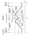
- FIG. 3 schematically shows varying thickness of the peripheral zone 16 in the circumferential direction. Also, FIG. 3 shows changes in the thickness along half the circumference on the right side of the lens during wear in front view, and its 12 o'clock position is defined as zero. Therefore, the vertical radial line 24 passes through the positions of 0 and 180 degrees whereas the horizontal radial line 26 passes through the positions of 90 degrees of the lens during wear.
- the peripheral zone 16 of this embodiment is formed in symmetry with respect to the vertical radial line 24 so that the changes in the thickness along half the circumference on the left side of the lens during wear in front view would be the same as shown in FIG. 3 .
- the thickness of the peripheral zone 16 varies also in the radial direction of the lens (left-right direction in FIG. 4 ) as schematically shown in FIG. 4 as a cross section along the horizontal radial line 26 (with a concavity 46 described later not formed) and a cross section along the vertical radial line 24 of the peripheral zone 16, and in general, the thickness decreases as it goes outward in the radial direction of the lens. Therefore, FIG. 3 shows variation of thickness in the circumferential direction at a location away from the lens central axis 14 by a given distance in the radial direction. Also, the dotted line in FIG. 3 shows the comparative example described below.
- an upper thin portion 38a and a lower thin portion 38b that are made relatively thin are formed in the peripheral zone 16 in both the upper and lower portions of the lens during wear. Then, at the locations in the peripheral zone 16 on the left and right sides of the lens during wear between the upper thin portion 38a and lower thin portion 38b in the circumferential direction, a right thick portion 40a and a left thick portion 40b are formed extending in the circumferential direction with larger thickness than the thin portions 38a and 38b.
- the one located on the right side (right in FIG. 1 ) in front view of the lens during wear is called the right thick portion 40a
- the one located on the left side (left in FIG. 1 ) is called the left thick portion 40b.
- the upper thin portion 38a and lower thin portion 38b are formed with a constant thickness Tc in a given length in the circumferential direction in the peripheral zone 16.
- the thickness Tc can vary between the upper thin portion 38a and the lower thin portion 38b, but it happens to be equal to each other in this embodiment.
- the thickness Tc of the thin portions 38a and 38b can be different from each other, and this thickness varies even in the radial direction of the lens in each of the upper thin portion 38a and lower thin portion 38b as shown in FIG 4 .
- the minimum thickness in all the thin portions 38a and 38b is preferably set in the range of 0.10mm to 0.20mm, and more preferably in the range of 0.13mm to 0.17mm.
- the left and right ends of the upper thin portion 38a and lower thin portion 38b in the circumferential direction are defined by a given thickness Tc.
- a central angle ⁇ 1 between the left and right ends of the upper thin portion 38a in the circumferential direction and a central angle ⁇ 2 between the left and right ends of the lower thin portion 38b are each preferably set in the range of 20 to 60 degrees, and more preferably in the range of 30 to 50 degrees.
- the central angles ⁇ 1 and ⁇ 2 of the thin portions 38a and 38b can be set to 20 degrees or more, the foreign-body sensation at the time of having the lens tucked under the upper or lower eyelid can be alleviated, and at the same time, by setting the central angle ⁇ 1 and ⁇ 2 to 60 degrees or less, the strength of the lens can be secured.
- the central angle ⁇ 1 of the upper thin portion 38a around the lens central axis 14 and the central angle ⁇ 2 of the lower thin portion 38b around the same are set equal to each other.
- the upper and lower thin portions 38a and 38b are each located with its central portion in the circumferential direction positioned on the vertical radial line 24.
- each of the upper thin portion 38a and lower thin portion 38b to be formed in 3-dimensional mirror symmetry with respect to a plane that extends in the direction of the lens optical axis passing through the vertical radial line 24 (a plane including the vertical radial line 24 and the lens optical axis), and at the same time, the upper and lower thin portions 38a and 38b are made in a form of 3-dimensional mirror symmetry to each other with respect to a plane that extends in the direction of the lens optical axis passing through the horizontal radial line 26 (a plane including the horizontal radial line 26 and the lens optical axis).
- the central angle ⁇ 1 of the upper thin portion 38a and the central angle ⁇ 2 of the lower thin portion 38b can be different from each other.
- the right thick portion 40a and the left thick portion 40b are formed in a given length in the circumferential direction in the peripheral zone 16 with larger thickness than that of the upper thin portion 38a and the lower thin portion 38b.
- a pair of transitional portions 42 and 42 with decreasing thickness toward the thin portions 38a and 38b in the circumferential direction are formed. Then, one side of each transitional portion 42 in the circumferential direction is connected to the upper thin portion 38a or the lower thin portion 38b, whereas the other side in the circumferential direction is connected to a thickest portion 44 having the maximum thickness Ta in each of the thick portions 40a and 40b.
- the thicknesses of the thick portions 40a and 40b are made to vary gradually by the transitional portions 42 and 42 formed on both sides thereof in the circumferential direction from the thickness Ta of the thickest portion 44 to the thickness Tc of the thin portions 38a and 38b in the circumferential direction.
- the maximum thickness Ta of the right thick portion 40a and the maximum thickness Ta of the left thick portion 40b are made equal to each other, but they can be made different from each other. Then, as is the case for the above thin portions 38a and 38b, the thickness varies in the radial direction of the lens in each of the right thick portion 40a and the left thick portion 40b as shown in FIG. 4 .
- the maximum thickness in all the thick portions 40a and 40b is preferably set in the range of 0.20mm to 0.45mm, more preferably in the range of 0.23mm to 0.42mm.
- the upper and lower ends of the right thick portion 40a and the left thick portion 40b in the circumferential direction are defined by the thickness Tc at the edges of the upper thin portion 38a and the lower thin portion 38b in the circumferential direction.
- the central angle ⁇ 1 between the upper and lower ends of the right thick portion 40a and the central angle ⁇ 2 between the upper and lower ends of the left thick portion 40b in the circumferential direction around the lens central axis 14 are each preferably set in the range of 120 to 160 degrees, more preferably in the range of 130 to 150 degrees.
- the central angles ⁇ 1 and ⁇ 2 By setting the central angles ⁇ 1 and ⁇ 2 to 120 degrees or more, the effect of turn restrictions caused by the push-out action of the upper eyelid can be exerted in a stable manner, and at the same time, by setting the central angles ⁇ 1 and ⁇ 2 to 160 degrees or less, the dimensions of the thin portions 38a and 38b in the circumferential direction can be maintained to secure the oxygen permeability of the contact lens 10.
- the concavity 46 is formed on the peripheral zone posterior surface 30 of the thick portions 40a and 40b.
- the concavity 46 is formed in a shape of concavity made on the peripheral zone posterior surface 30 and is opened up thereto.
- the number of the concavity 46 formed in each of the thick portions 40a and 40b is not restricted and the concavity 46 can be formed in plurality, but in this embodiment, it is formed one each at the midpoint of each of the thick portions 40a and 40b in the circumferential direction stretching over the thickest portions 44 and 44.
- the right and left thick portions 40a and 40b in this embodiment are each made to be a transitional portion, as a whole, that changes the thickness in the circumferential direction by having the end of the transitional portion 42 toward the center in the circumferential direction connected to the concavity 46 at the thickest portion 44.
- the concavity 46 is formed symmetrically in the up-down direction (left-right direction in FIG. 3 ) of the lens during wear in the cross sections of the thick portions 40a and 40b in the circumferential direction.
- a bottom surface 47 of the concavity 46 in this embodiment is made in a form of a double taper having slopes 50 and 50 that gradually reduce the depth as they go out toward the periphery on both sides of a bottom portion 48 which is the deepest of all.
- the thickness at the formation of the concavity 46 is assumed to be the smallest at the bottom portion 48, and the minimum thickness Tb at the formation of the concavity 46 is set larger than the thickness Tc of the thin portions 38a and 38b. This enables to maintain the shape retention capacity of the contact lens 10.
- the minimum thickness Tb at the formation of the concavity 46 is preferably set to 1/2 to 9/10 of the maximum thickness Ta of the thick portions 40a and 40b.
- the minimum thickness Tb at the formation of the concavity 46 is set to 1/2 or more of the maximum thickness Ta of the thick portions 40a and 40b, it is possible to maintain morphological stability of the contact lens 10 and to prevent the concavity 46 from getting too deep, thus making the fabrication of molds and metal molds for casting said molds, described later, easier. Also, by setting the minimum thickness of Tb at the formation of the concavity 46 to 9/10 or less of the maximum thickness Ta of the thick portions 40a and 40b, it is possible to effectively obtain effects of improved oxygen permeability and enhanced wearing sensation by virtue of thinning the formation of the concavity 46.
- the central angle ⁇ at the concavity 46 around the lens central axis 14 is preferably set in the range of 20 to 60 degrees, more preferably in the range of 30 to 50 degrees.
- the central angle ⁇ at the concavity 46 is set to 20 degrees or more, the length of the concavity 46 in the circumferential direction can be properly maintained to facilitate an effect of improved oxygen permeability and the flexural deformation due to the concavity 46, whereas, by setting the central angle ⁇ at the concavity 46 to 60 degrees or less, the strength of the lens at the thick portions 40a and 40b can be secured.
- each of the thick portions 40a and 40b changes its thickness gradually from Tc to Ta (or from Ta to Tc) at the transitional portion 42 due to the inclination of the transitional portion 42 in the circumferential direction.
- the inclination angle of the transitional portion 42 in the circumferential direction is deemed to represent changes in thickness per unit length in the circumferential direction, and more specifically, is expressed by (Ta-Tc) / ⁇ , assuming the central angle of the transitional portion 42 between the upper and lower ends in the circumferential direction is ⁇ .
- each of the thick portions 40a and 40b gradually changes its thickness from Ta to Tb (or from Tb to Ta) at the slope 50 due to the inclination of the slope 50 of the concavity 46 in the circumferential direction. Since the slope 50 runs half way through the concavity 46, the inclination angle of the slope 50 in the circumferential direction can be expressed by (Ta-Tb) / ( ⁇ / 2) in the same way as the transitional portion 42. Then, the inclination angle (Ta-Tb) / ( ⁇ / 2) of the slope 50 of the concavity 46 in the circumferential direction is preferably set to the inclination angle of the transitional portion 42 in the circumferential direction (Ta-Tc) / ⁇ or more.
- the inclination of the slope 50 of the concavity 46 is preferably set to no less than that of the transitional portion 42 in FIG. 3 . This way, it is possible to maintain a certain depth of the concavity 46 without increasing the dimension thereof in the circumferential direction, thus improving the design freedom in forming the concavity 46.
- the right and left thick portions 40a and 40b as a whole including the concavity 46 and the transitional portions 42 and 42 are each in a form of 3-dimentional mirror symmetry with respect to a plane that includes the horizontal radial line 26 and the lens optical axis.
- the right and left thick portions 40a and 40b are configured in such a way that the bottom portion 48 of the concavity 46 formed at the center in the circumferential direction is positioned on the horizontal radial line 26 of the lens during wear, and the concavity 46 of the right thick portion 40a and that of the left thick portion 40b are made symmetrical to each other in the left-right direction on the horizontal radial line 26 during wear.
- the central angle ⁇ 1 of the right thick portion 40a and the central angle ⁇ 2 of the left thick portion 40b are made equal to each other, which makes the right and left thick portions 40a and 40b in a form of 3-dimensional mirror symmetry to each other with respect to a plane that includes the vertical radial line 24 and the lens optical axis.
- the central angle ⁇ 1 of the right thick portion 40a and the central angle ⁇ 2 of the left thick portion 40b can be made different from each other.
- the distance between the upper and lower eyelids of a human eye tends to get smaller toward the nose than toward the ear when the eye is open as usual, it is possible, in response to it, to further improve the wearing sensation and positioning accuracy in the circumferential direction due to the eyelid action by means of setting the circumferential length (central angle) of the lens during wear on the nose side smaller than that of the ear side in either the right thick portion 40a or the left thick portion 40b.
- the peripheral zone posterior surface 30 in a smooth form without any bend in the cross section in the radial direction of the lens. More preferably, it is in a continuous and smooth form without any edgy bend by having the inclination angle of the tangent line continuously vary in the radial direction substantially all across the lens posterior surface 20 including a junction 52, which is a connection boundary between the optical zone posterior surface 28 and the peripheral zone posterior surface 30.
- the contact lens 10 described above has a concavity 46 formed in each of the right thick portion 40a and the left thick portion 40b and is able to alleviate the foreign-body sensation caused by the pressure of the thick portions 40a and 40b by means of partially reducing the thickness thereof on both sides.
- the concavity 46 opens up on the lens posterior surface 20, it is possible to alleviate the pressure caused by an pinguecula by means of forming the concavity 46 at a position corresponding to the pinguecula, for example.
- by reducing the thickness of the thick portions 40a and 40b on both sides at the formation of the concavity 46 it is possible to improve the oxygen permeability.
- the concavity 46 in each of the right thick portion 40a and the left thick portion 40b is positioned in left-right symmetry on the horizontal radial line 26, which is the center of the contact lens 10 in the up-down direction, the flexural deformation can be generated effectively.
- the contact lens 10 according to this embodiment is in an overall form of a double-thin type comprising the thin portions 38a, 38b on the upper and lower sides and the thick portions 40a, 40b on the left and right sides.
- This enables to obtain the effect of turn restrictions almost to the same extent as the conventional double-thin type. Therefore, it can be favorably adopted in some lenses, such as a toric lens and the like for which a particular radial axis is set in connection with the optical properties of the optical zone 12.
- the thin portions 38a, 38b on the upper and lower sides and the thick portions 40a, 40b on the left and right sides are in a symmetrical form with respect to both the horizontal radial line 26 and the vertical radial line 24, including the concavity 46.
- This allows the concavity 46 to be arranged in a good balance in both up-down and left-right directions so as to improve the oxygen permeability in a good balance in both up-down and left-right directions while generating the flexural deformation in a stable manner.
- the thickness of the peripheral zone 16 in a good balance in both up-down and left-right directions, an even better effect of turn restrictions can be obtained.
- the contact lens 10 with the structure described above can be formed by means of directly cutting a block made from appropriate materials through polymerization molding in advance, but considering mass productivity and stable product quality, it can be favorably manufactured by molding or a combination of molding and cutting.
- a male mold 62 having a mold surface 60 in an aspheric convex form corresponding to the lens posterior surface 20 and a female mold 66 having a mold surface 64 in a spherical concave form corresponding to the lens anterior surface 18 are used, as shown in FIG. 5 .
- a substantially water-tight mold cavity 68 is created between the two mold surfaces 60, 64.
- the intended contact lens 10 has its lens anterior surface 18 in a form of rotating body, whereas its lens posterior surface 20 is in a form of non-rotating body having the optical zone posterior surface 28 and the peripheral zone posterior surface 30.
- This allows both the non-rotating body of the optical zone 12 as well as the thin portions 38a, 38b and the thick portions 40a, 40b to be formed by the lens posterior surface 20. Therefore, by properly setting a form of the mold surface 60 of the male mold 62 that determines the surface configuration of the lens posterior surface 20, the male mold 62 in which positioning in the circumferential direction is already done between the optical zone 12 and those thin portions 38a, 38b and the thick portions 40a, 40b can be obtained, thus enabling a high-precision positioning in the circumferential direction.
- the lens anterior surface 18 is in a form of rotating body, there is no need for positioning the molds 62 and 66 in the circumferential direction. Also, even in manufacturing various types of contact lenses with different cylindrical diopters of the optical zone 12, for example, one can deal with it by preparing several kinds of male molds 62 that determine the form of the lens posterior surface 20 and share the female mold 66 that determines the form of the lens anterior surface 18. Therefore, the number of metal molds for producing the male and female molds 62 and 66 can be saved significantly and the intended contact lens 10 can be favorably manufactured with good processing efficiency and precision.
- FIG. 6 shows a contact lens according to the second embodiment of the present invention.
- a continuous portion 70 that extends in the circumferential direction with a constant thickness Ta is formed at the center sandwiched by the transitional portions 42 and 42 in the circumferential direction on both sides thereof.
- the thickness Ta of the continuous portion 70 is assumed to be the maximum thickness dimension of the thick portion 40 in the circumferential direction.
- a concavity 72 is formed at the center of the continuous portion 70 in the circumferential direction. According to this embodiment, the thickness of the thick portion 40 can be maintained at the continuous portion 70 to obtain a better shape retention capacity of the lens and a better effect of turn restrictions. Then, by having the maximum thickness and formation of the concavity 72 at the center in the circumferential direction of the continuous portion 70 with relatively low oxygen permeability, the oxygen permeability of the thick portion 40 can be effectively improved.
- the central angle ⁇ of the continuous portion 70 around the lens central axis 14 is preferably set in the range of 40 to 70 degrees, more preferably in the range of 50 to 60 degrees.
- the central angle ⁇ of the continuous portion 70 is set to 40 degrees or more, it is possible to maintain the thickness of the thick portion 40 and obtain a better shape retention capacity of the lens and a better effect of turn restrictions, whereas, by setting the central angle ⁇ of the continuous portion 70 to 70 degrees or less, it is possible to reduce the foreign-body sensation caused by the pressure of the continuous portion 70.
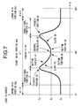
- FIG. 7 shows a contact lens according to the third embodiment of the present invention.
- the transitional portions 42 and 42 on both sides of the thick portion 40 in the circumferential direction are each connected to the thin portion 38 and the thickest portion 44 in a smooth way without any edgy bend in cross section in the circumferential direction.
- a concavity 80 according to this embodiment is made in a curved concave form in cross section in the circumferential direction. This allows the concavity 80 to keep its volume larger and reduce its pressure against the pinguecula and the like, for example.
- a central protrusion 82 is formed slightly protruding out in the direction of the opening on the concavity 80 (upward in FIG. 7 ), and a pair of bottom portions 48 and 48 with the minimum thickness Tb are formed on both sides sandwiching the central protrusion 82 in the circumferential direction. This way, it is also possible to form portions of minimum thickness at several locations of the formation of the concavity.
- FIG. 8 shows a contact lens according to the fourth embodiment of the present invention.
- three concavities 90, 90 and 90 are formed in sequence in the circumferential direction in one thick portion 40. These concavities 90, 90 and 90 are made in approximately the same form.
- the thick portion 40 of this embodiment, including these three concavities 90, 90 and 90 is in a form of symmetry with respect to the horizontal radial line 26. As evident from this embodiment, it is possible to form multiple concavities in a single thick portion. This way, the oxygen permeability and the amount of flexural deformation at the time of blinking in the thick portion 40 can be set at a higher level.
- FIG. 9 shows a contact lens according to the fifth embodiment of the present invention.
- a concavity 102 which is located at the center in the circumferential direction, and a pair of concavities 104 located on both sides in the circumferential direction of the concavity 102 are formed.
- the cross section of the concavity 102 in the circumferential direction is made in an approximate form of a "V" that is symmetrical in the circumferential direction
- the cross sections of the pair of concavities 104 in the circumferential direction are each made in an approximate form of a "V” that is asymmetrical in the circumferential direction with a larger depth at the center in the circumferential direction than that toward the outer periphery.
- the depth of the concavity 102 is made larger than that of the pair of concavities 104
- the thickness of the bottom portion 48 of the concavity 102 is assumed to be the minimum thickness Tb at the formation of the concavities 102 and 104.
- the minimum thickness Tb at the formation of concavities 102 and 104 in this embodiment is made larger than 1/2 of the maximum thickness Ta of the thick portion 40.
- the cross sectional configuration of the concavity in the circumferential direction is not limited to those symmetrical in the same direction. Meanwhile, it is possible to consider the concavities 102 and 104 of this embodiment as a single concavity and deem it as having a symmetrical form with respect to the horizontal radial line 26.
- each embodiment described above is just an example.
- the specific form of the concavity is not limited to those described above, and is to be set as appropriate in consideration of the required oxygen permeability and the amount of displacement of the lens and the like.
- the specific forms of those concavities can be made similar to each other or different from each other.
- they do not necessarily have to be positioned symmetrically in the up-down direction in the thick portion of the lens during wear, and can be positioned off-centered in the up-down direction during wear.
- the pair of transitional portions formed on both sides in the circumferential direction are not limited to those having a symmetrical form with respect to the horizontal radial line, but, for example, their dimensions in the circumferential direction can be different from each other, or the thicknesses at both ends of the pair of transitional portions in the circumferential direction can be different from each other by means of making the thicknesses of the thin portions on the upper and lower sides different from each other or the like.
- the optical zone and the thin and thick portions are formed by making the lens posterior surface in a form of a non-rotating body, but the non-rotating body of the optical zone and the thin and thick portions can be formed on the lens anterior surface by making the lens posterior surface in a form of a rotating body while making the lens anterior surface in a form of a non-rotating body, for example.
- the specific optical properties and geometric forms in the above embodiment are just examples.
- the contact lens in the form according to the present invention is designed to be able to respond to various optical properties and geometric forms required by many contact lens wearers by appropriately changing the setting of various values including the outer diameter (DIA.), curvature radius of the lens posterior surface (base curve), optical properties of the optical zone, inner and outer diameters of the peripheral zone, and in many cases, the product will be introduced to the market as a series combining multiple types with changed settings of various values at appropriate intervals.
- DIA. outer diameter
- base curve base curve
- optical properties of the optical zone inner and outer diameters of the peripheral zone
- the product will be introduced to the market as a series combining multiple types with changed settings of various values at appropriate intervals.
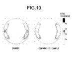
- FIG. 10 shows thickness distributions.
- An example with a structure according to the first embodiment and a comparative example with a structure according to the conventional configuration are prepared.
- the comparative example does not have the concavity of the example, and has its portion corresponding to the concavity of the example formed in a constant thickness Ta as shown by the dotted line in FIG. 3 . Therefore, the comparative example is formed with the same lens material as the example, and its thickness and the central angle of each portion mentioned above are the same as the example, except for the concavity.
- the oxygen permeability is expressed by Dk /T.
- Dk represents an oxygen permeability coefficient of the lens material [(cm 2 /sec) • (ml • O 2 (STP) /ml • mmHg)] and T represents the lens thickness (cm). Since the example and comparative example are formed with the same lens material, the values of Dk are equal to each other.
- Table 1 shows a result of examination on the wearing sensation of the working and comparative examples of the contact lens worn by 30 eyes of 15 users. As evident from Table 1, it was confirmed that a better wearing sensation than the comparative examples is obtained using the contact lens with a structure according to the present invention.
Landscapes
- Health & Medical Sciences (AREA)
- Ophthalmology & Optometry (AREA)
- Physics & Mathematics (AREA)
- General Health & Medical Sciences (AREA)
- General Physics & Mathematics (AREA)
- Optics & Photonics (AREA)
- Eyeglasses (AREA)
Claims (14)
- Kontaktlinse (10), die einen mittleren optischen Bereich (12) und einen Umfangsbereich (16), der den optischen Bereich (12) umgibt, enthält, wobei die Kontaktlinse (10) dadurch gekennzeichnet ist, dass:der optische Bereich (12) keine Abweichung von einem Schwerpunkt durch ein Prisma aufweist;ein Paar dünner Abschnitte (38a, 38b) in dem Umfangsbereich (16) gebildet ist, die sich während des Tragens mit einer konstanten Dicke auf der oberen und der unteren Seite der Linse (10) in einer Umfangsrichtung erstrecken;ein Paar dicker Abschnitte (40a, 40b) in dem Umfangsbereich (16) gebildet ist, die sich während des Tragens mit einer größeren Dicke als die dünnen Abschnitte (38a, 38b) auf der linken und der rechten Seite der Linse (10) in der Umfangsrichtung erstrecken;eine hintere Fläche (30) von jedem Abschnitt des Paars dicker Abschnitte (40a, 40b) mindestens eine Konkavität (46, 72, 80, 90, 102, 104) aufweist, so dass jeweilige Konkavitäten (46, 72, 80, 90, 102, 104) während des Tragens symmetrisch in einer Links-Rechts-Richtung positioniert sind; undeine minimale Dicke an einem Abschnitt, an dem die Konkavität (46, 72, 80, 90, 102, 104) gebildet ist, größer als die Dicke der dünnen Abschnitte (38a, 38b) ist.
- Kontaktlinse (10) nach Anspruch 1, wobei eine der mindestens einen Konkavität (46, 72, 80, 90, 102, 104) in jedem Abschnitt des Paars dicker Abschnitte (40a, 40b) auf einer horizontalen radialen Linie (26) gebildet ist, die sich während des Tragens durch einen zentrale Achse der Linse (14) in die Links-Rechts-Richtung erstreckt.
- Kontaktlinse (10) nach Anspruch 1 oder 2, wobei das Paar dünner Abschnitte (38a, 38b), das sich während des Tragens auf der oberen und der unteren Seite der Linse (10) befindet, und das Paar dicker Abschnitte (40a, 40b), das sich während des Tragens auf der linken und der rechten Seite der Linse (10) befindet, in Bezug auf zwei radiale Linien (24, 26) symmetrisch gebildet sind, das heißt, die horizontale radiale Linie (26), die sich während des Tragens durch die zentrale Achse der Linse (14) in die Links-Rechts-Richtung erstreckt, und eine vertikale radiale Linie (24), die sich während des Tragens durch die zentrale Achse der Linse (14) in eine Aufwärts/Abwärts-Richtung erstreckt, einschließlich der in jedem Abschnitt des Paars dicker Abschnitte (40a, 40b) gebildeten Konkavität (46, 72, 80, 90, 102, 104).
- Kontaktlinse (10) nach einem der Ansprüche 1-3, wobei die minimale Dicke an dem Abschnitt, an dem die Konkavität (46, 72, 80, 90, 102, 104) gebildet ist, in einem Bereich von 1/2 bis 9/10 einer maximalen Dicke der dicken Abschnitte (40a, 40b) eingestellt ist.
- Kontaktlinse (10) nach einem der Ansprüche 1-4, wobei beide Seiten in der Umfangsrichtung der dicken Abschnitte (40a, 40b) so hergestellt sind, dass sie Übergangsabschnitte (42) sind, die sich allmählich in Richtung der dünnen Abschnitte (38a, 38b) verdünnen.
- Kontaktlinse (10) nach Anspruch 5, wobei eine Mitte des dicken Abschnitts (40a, 40b) in der Umfangsrichtung so hergestellt ist, dass sie ein durchgehender Abschnitt (70) ist, der sich mit einer konstanten Dicke in die Umfangsrichtung erstreckt, und ein zentraler Winkel Δ um die zentrale Achse der Linse (14) in dem durchgehenden Abschnitt (70) in einem Bereich von 40 bis 70 Grad eingestellt ist.
- Kontaktlinse (10) nach Anspruch 5 oder 6, wobei die Konkavität (46, 72, 102, 104) in einer doppelt keilförmigen unteren Fläche (47) gebildet ist, die ihre Tiefe in Richtung beider Seiten in der Umfangsrichtung allmählich verringert, während ein Neigungswinkel der Konkavität (46, 72, 102, 104) an der unteren Fläche (47) in der Umfangsrichtung gleich dem des Übergangsabschnitts (42) des dicken Abschnitts (40a, 40b) oder größer als dieser gemacht ist.
- Kontaktlinse (10) nach einem der Ansprüche 1-7, wobei ein zentraler Winkel α um die zentrale Achse der Linse (14) in den dünnen Abschnitten (38a, 38b) in einem Bereich von 20 bis 60 Grad eingestellt ist.
- Kontaktlinse (10) nach einem der Ansprüche 1-8, wobei ein zentraler Winkel β um die zentrale Achse der Linse (14) in den dicken Abschnitten (40a, 40b) in einem Bereich von 120 bis 160 Grad eingestellt ist.
- Kontaktlinse (10) nach einem der Ansprüche 1-9, wobei ein zentraler Winkel γ um die zentrale Achse der Linse (14) an der Konkavität (46, 72, 80, 90, 102, 104) ein einem Bereich von 20 bis 60 Grad eingestellt ist.
- Kontaktlinse (10) nach einem der Ansprüche 1-10, wobei eine minimale Dicke des dünnen Abschnitts (38a, 38b) in einem Bereich von 0,10 mm bis 0,20 mm eingestellt ist.
- Kontaktlinse (10) nach einem der Ansprüche 1-11, wobei die maximale Dicke des dicken Abschnitts (40a, 40b) in einem Bereich von 0,20 mm bis 0,45 mm eingestellt ist.
- Kontaktlinse (10) nach einem der Ansprüche 1-12, wobei eine vordere Fläche (18) des optischen Bereichs (12) und des Umfangsbereichs (16) so hergestellt ist, dass sie einen sich drehenden Körper um die zentrale Achse der Linse (14) bildet, und eine bestimmte Achse in einer radialen Richtung in Verbindung mit den optischen Eigenschaften des optischen Bereichs (12) eingestellt wird, indem die hinteren Flächen (28, 30) des optischen Bereichs (12) und des Umfangsbereichs (16) so hergestellt sind, dass sie einen sich nicht drehenden Körper um die zentrale Achse der Linse (14) bilden, während das Paar dünner Abschnitte (38a, 38b), das Paar dicker Anschnitte (40a, 40b) und die Konkavität (46, 72, 80, 90, 102, 104) in jedem Abschnitt der dicken Abschnitte (40a, 40b) in dem Umfangsbereich vorgesehen sind.
- Kontaktlinse (10) nach einem der Ansprüche 1-13, wobei der optische Bereich (12) jener einer torischen Linse, eine bifokalen Linse, einer multifokalen Linse einer torischen bifokalen Linse, einer torischen multifokalen Linse, einer dezentrierten torischen Linse, einer dezentrierten bifokalen Linse, einer dezentrierten multifokalen Linse, einer dezentrierten torischen bifokalen Linse oder einer dezentrierten torischen multifokalen Linse ist.
Applications Claiming Priority (1)
| Application Number | Priority Date | Filing Date | Title |
|---|---|---|---|
| PCT/JP2009/006172 WO2011061790A1 (ja) | 2009-11-17 | 2009-11-17 | コンタクトレンズ |
Publications (3)
| Publication Number | Publication Date |
|---|---|
| EP2503380A1 EP2503380A1 (de) | 2012-09-26 |
| EP2503380A4 EP2503380A4 (de) | 2013-05-01 |
| EP2503380B1 true EP2503380B1 (de) | 2014-04-23 |
Family
ID=44059294
Family Applications (1)
| Application Number | Title | Priority Date | Filing Date |
|---|---|---|---|
| EP09851416.9A Active EP2503380B1 (de) | 2009-11-17 | 2009-11-17 | Kontaktlinse |
Country Status (4)
| Country | Link |
|---|---|
| US (1) | US8985764B2 (de) |
| EP (1) | EP2503380B1 (de) |
| JP (1) | JP5335099B2 (de) |
| WO (1) | WO2011061790A1 (de) |
Families Citing this family (16)
| Publication number | Priority date | Publication date | Assignee | Title |
|---|---|---|---|---|
| US8814350B2 (en) * | 2012-02-13 | 2014-08-26 | Johnson & Johnson Vision Care, Inc. | Dynamic stabilization zones for contact lenses |
| US9046699B2 (en) * | 2012-03-13 | 2015-06-02 | Johnson & Johnson Vision Care, Inc. | Dynamic fluid zones in contact lenses |
| AU2015201837B2 (en) * | 2012-03-13 | 2016-09-29 | Johnson & Johnson Vision Care, Inc. | Dynamic fluid zones in contact lenses |
| AU2016216742B2 (en) * | 2012-03-13 | 2017-07-13 | Johnson & Johnson Vision Care, Inc. | Dynamic fluid zones in contact lenses |
| TWI588560B (zh) | 2012-04-05 | 2017-06-21 | 布萊恩荷登視覺協會 | 用於屈光不正之鏡片、裝置、方法及系統 |
| EP2876486B1 (de) * | 2012-07-18 | 2019-02-13 | Menicon Co., Ltd. | Kontaktlinse und herstellungsverfahren für die kontaktlinse |
| US9823493B2 (en) | 2012-08-30 | 2017-11-21 | Johnson & Johnson Vision Care, Inc. | Compliant dynamic translation zones for contact lenses |
| US9201250B2 (en) | 2012-10-17 | 2015-12-01 | Brien Holden Vision Institute | Lenses, devices, methods and systems for refractive error |
| JP2015533430A (ja) | 2012-10-17 | 2015-11-24 | ブリエン ホールデン ビジョン インスティテュートBrien Holden Vision Institute | 屈折異常用のレンズ、デバイス、方法、及びシステム |
| WO2014128744A1 (ja) * | 2013-02-19 | 2014-08-28 | 株式会社メニコン | 老視用コンタクトレンズセットおよび老視用コンタクトレンズの選択方法 |
| US9389434B2 (en) * | 2013-11-22 | 2016-07-12 | Johnson & Johnson Vision Care, Inc. | Contact lenses with improved oxygen transmission |
| US9995946B2 (en) * | 2014-06-13 | 2018-06-12 | Pegavision Corporation | Toric lens |
| JP6646531B2 (ja) * | 2016-06-20 | 2020-02-14 | Hoya株式会社 | コンタクトレンズおよびその製造方法 |
| US10786959B2 (en) * | 2016-07-18 | 2020-09-29 | Johnson & Johnson Vision Care, Inc | Mold for contact lens with non-rotationally symmetric rim or edge |
| US20220334409A1 (en) * | 2019-09-25 | 2022-10-20 | Nthalmic Holding Pty Ltd | A contact lens solution for myopia management |
| EP4369079A1 (de) | 2022-11-11 | 2024-05-15 | UNICON Optical Co., LTD. | Kontaktlinse |
Family Cites Families (18)
| Publication number | Priority date | Publication date | Assignee | Title |
|---|---|---|---|---|
| EP0042023B1 (de) * | 1980-06-12 | 1983-09-28 | Biolens Sa | Kontaktlinse für gerichtete optische Korrektur |
| AU629725B2 (en) | 1990-01-24 | 1992-10-08 | Novartis Ag | Contact lens and process for the manufacture thereof |
| DE4012478A1 (de) * | 1990-04-19 | 1991-10-24 | Heinrich Woehlk Inst Fuer Cont | Kontaktlinse mit lagestabilisierung |
| TW210380B (de) * | 1992-04-23 | 1993-08-01 | Ciba Geigy Ag | |
| US5650837A (en) | 1995-05-04 | 1997-07-22 | Johnson & Johnson Vision Products, Inc. | Rotationally stable contact lens designs |
| FR2760853B1 (fr) * | 1997-03-17 | 1999-05-28 | Essilor Int | Lentille de contact a bossages palpebraux |
| DE19726918A1 (de) * | 1997-06-25 | 1999-01-07 | Woehlk Contact Linsen Gmbh | Multifokale Kontaktlinse |
| JPH11174388A (ja) * | 1997-12-12 | 1999-07-02 | Hoya Health Care Kk | トーリックコンタクトレンズ |
| SG83139A1 (en) | 1998-08-10 | 2001-09-18 | Johnson & Johnson Vision Prod | Dynamically stabilized contact lenses |
| US6886936B2 (en) | 2000-07-28 | 2005-05-03 | Ocular Sciences, Inc. | Contact lenses with blended microchannels |
| US6779888B2 (en) | 2000-07-28 | 2004-08-24 | Ocular Sciences, Inc. | Contact lenses with microchannels |
| AUPR276601A0 (en) * | 2001-01-31 | 2001-02-22 | Newman, Steve | A contact lens for refractive correction and capable of engagement with an eye either inside out or right way out |
| US6921168B2 (en) * | 2002-07-24 | 2005-07-26 | Novartis Ag | Translating contact lens having a ramped ridge |
| US6939005B2 (en) | 2003-08-20 | 2005-09-06 | Johnson & Johnson Vision Care Inc. | Rotationally stabilized contact lenses |
| US7201480B2 (en) * | 2004-05-20 | 2007-04-10 | Johnson & Johnson Vision Care, Inc. | Methods for rotationally stabilizing contact lenses |
| WO2008062503A1 (fr) * | 2006-11-20 | 2008-05-29 | Menicon Co., Ltd. | Lentille de contact et son procédé de fabrication |
| JP5149202B2 (ja) * | 2007-01-16 | 2013-02-20 | 株式会社メニコン | コンタクトレンズの製造方法 |
| EP2278387B1 (de) * | 2008-05-13 | 2015-07-01 | Menicon Co., Ltd. | Kontaktlinse |
-
2009
- 2009-11-17 US US13/503,784 patent/US8985764B2/en active Active
- 2009-11-17 WO PCT/JP2009/006172 patent/WO2011061790A1/ja active Application Filing
- 2009-11-17 EP EP09851416.9A patent/EP2503380B1/de active Active
- 2009-11-17 JP JP2011541731A patent/JP5335099B2/ja active Active
Also Published As
| Publication number | Publication date |
|---|---|
| EP2503380A1 (de) | 2012-09-26 |
| EP2503380A4 (de) | 2013-05-01 |
| JPWO2011061790A1 (ja) | 2013-04-04 |
| JP5335099B2 (ja) | 2013-11-06 |
| WO2011061790A1 (ja) | 2011-05-26 |
| US8985764B2 (en) | 2015-03-24 |
| US20120206692A1 (en) | 2012-08-16 |
Similar Documents
| Publication | Publication Date | Title |
|---|---|---|
| EP2503380B1 (de) | Kontaktlinse | |
| EP2278387B1 (de) | Kontaktlinse | |
| EP1496388B1 (de) | Kontaktlinse und kontaktlinsenherstellungsverfahren | |
| US5020898A (en) | Contact lens for correction of astigmatism | |
| US6409339B1 (en) | Multifocal lens, and method for production thereof | |
| US4193672A (en) | Contact lens with improved interior surface | |
| US8668332B2 (en) | Toric contact lens and method for manufacturing the same | |
| EP2956817B1 (de) | Kontaktlinsenstabilisierung | |
| CN109073914B (zh) | 隐形眼镜及其制造方法 | |
| JP5946981B2 (ja) | ディセンタタイプのコンタクトレンズおよびディセンタタイプのコンタクトレンズセット | |
| EP2876486B1 (de) | Kontaktlinse und herstellungsverfahren für die kontaktlinse | |
| JP5642895B2 (ja) | コンタクトレンズおよびコンタクトレンズの製造方法 | |
| JP2006267316A (ja) | 累進屈折力レンズの製造方法 | |
| CN112147795B (zh) | 角膜塑形镜制造方法、角膜塑形镜销售方法与角膜塑形镜组件 | |
| CN210038367U (zh) | 角膜塑形镜组件 | |
| CN109564357B (zh) | 角膜塑形镜 | |
| JP5536265B2 (ja) | コンタクトレンズ | |
| KR101556997B1 (ko) | 토릭렌즈용 몰드 | |
| CN115071183A (zh) | 一种差异化离焦增量树脂镜片的制造方法 |
Legal Events
| Date | Code | Title | Description |
|---|---|---|---|
| PUAI | Public reference made under article 153(3) epc to a published international application that has entered the european phase |
Free format text: ORIGINAL CODE: 0009012 |
|
| 17P | Request for examination filed |
Effective date: 20120425 |
|
| AK | Designated contracting states |
Kind code of ref document: A1 Designated state(s): AT BE BG CH CY CZ DE DK EE ES FI FR GB GR HR HU IE IS IT LI LT LU LV MC MK MT NL NO PL PT RO SE SI SK SM TR |
|
| DAX | Request for extension of the european patent (deleted) | ||
| A4 | Supplementary search report drawn up and despatched |
Effective date: 20130405 |
|
| RIC1 | Information provided on ipc code assigned before grant |
Ipc: G02C 7/04 20060101AFI20130328BHEP |
|
| GRAP | Despatch of communication of intention to grant a patent |
Free format text: ORIGINAL CODE: EPIDOSNIGR1 |
|
| INTG | Intention to grant announced |
Effective date: 20131111 |
|
| GRAS | Grant fee paid |
Free format text: ORIGINAL CODE: EPIDOSNIGR3 |
|
| GRAA | (expected) grant |
Free format text: ORIGINAL CODE: 0009210 |
|
| AK | Designated contracting states |
Kind code of ref document: B1 Designated state(s): AT BE BG CH CY CZ DE DK EE ES FI FR GB GR HR HU IE IS IT LI LT LU LV MC MK MT NL NO PL PT RO SE SI SK SM TR |
|
| REG | Reference to a national code |
Ref country code: GB Ref legal event code: FG4D |
|
| REG | Reference to a national code |
Ref country code: CH Ref legal event code: EP |
|
| REG | Reference to a national code |
Ref country code: AT Ref legal event code: REF Ref document number: 664168 Country of ref document: AT Kind code of ref document: T Effective date: 20140515 |
|
| REG | Reference to a national code |
Ref country code: IE Ref legal event code: FG4D |
|
| REG | Reference to a national code |
Ref country code: DE Ref legal event code: R096 Ref document number: 602009023596 Country of ref document: DE Effective date: 20140605 |
|
| REG | Reference to a national code |
Ref country code: AT Ref legal event code: MK05 Ref document number: 664168 Country of ref document: AT Kind code of ref document: T Effective date: 20140423 |
|
| REG | Reference to a national code |
Ref country code: NL Ref legal event code: VDEP Effective date: 20140423 |
|
| REG | Reference to a national code |
Ref country code: LT Ref legal event code: MG4D |
|
| PG25 | Lapsed in a contracting state [announced via postgrant information from national office to epo] |
Ref country code: BG Free format text: LAPSE BECAUSE OF FAILURE TO SUBMIT A TRANSLATION OF THE DESCRIPTION OR TO PAY THE FEE WITHIN THE PRESCRIBED TIME-LIMIT Effective date: 20140723 Ref country code: NO Free format text: LAPSE BECAUSE OF FAILURE TO SUBMIT A TRANSLATION OF THE DESCRIPTION OR TO PAY THE FEE WITHIN THE PRESCRIBED TIME-LIMIT Effective date: 20140723 Ref country code: LT Free format text: LAPSE BECAUSE OF FAILURE TO SUBMIT A TRANSLATION OF THE DESCRIPTION OR TO PAY THE FEE WITHIN THE PRESCRIBED TIME-LIMIT Effective date: 20140423 Ref country code: CY Free format text: LAPSE BECAUSE OF FAILURE TO SUBMIT A TRANSLATION OF THE DESCRIPTION OR TO PAY THE FEE WITHIN THE PRESCRIBED TIME-LIMIT Effective date: 20140423 Ref country code: FI Free format text: LAPSE BECAUSE OF FAILURE TO SUBMIT A TRANSLATION OF THE DESCRIPTION OR TO PAY THE FEE WITHIN THE PRESCRIBED TIME-LIMIT Effective date: 20140423 Ref country code: GR Free format text: LAPSE BECAUSE OF FAILURE TO SUBMIT A TRANSLATION OF THE DESCRIPTION OR TO PAY THE FEE WITHIN THE PRESCRIBED TIME-LIMIT Effective date: 20140724 Ref country code: NL Free format text: LAPSE BECAUSE OF FAILURE TO SUBMIT A TRANSLATION OF THE DESCRIPTION OR TO PAY THE FEE WITHIN THE PRESCRIBED TIME-LIMIT Effective date: 20140423 Ref country code: IS Free format text: LAPSE BECAUSE OF FAILURE TO SUBMIT A TRANSLATION OF THE DESCRIPTION OR TO PAY THE FEE WITHIN THE PRESCRIBED TIME-LIMIT Effective date: 20140823 |
|
| PG25 | Lapsed in a contracting state [announced via postgrant information from national office to epo] |
Ref country code: ES Free format text: LAPSE BECAUSE OF FAILURE TO SUBMIT A TRANSLATION OF THE DESCRIPTION OR TO PAY THE FEE WITHIN THE PRESCRIBED TIME-LIMIT Effective date: 20140423 Ref country code: SE Free format text: LAPSE BECAUSE OF FAILURE TO SUBMIT A TRANSLATION OF THE DESCRIPTION OR TO PAY THE FEE WITHIN THE PRESCRIBED TIME-LIMIT Effective date: 20140423 Ref country code: HR Free format text: LAPSE BECAUSE OF FAILURE TO SUBMIT A TRANSLATION OF THE DESCRIPTION OR TO PAY THE FEE WITHIN THE PRESCRIBED TIME-LIMIT Effective date: 20140423 Ref country code: AT Free format text: LAPSE BECAUSE OF FAILURE TO SUBMIT A TRANSLATION OF THE DESCRIPTION OR TO PAY THE FEE WITHIN THE PRESCRIBED TIME-LIMIT Effective date: 20140423 Ref country code: LV Free format text: LAPSE BECAUSE OF FAILURE TO SUBMIT A TRANSLATION OF THE DESCRIPTION OR TO PAY THE FEE WITHIN THE PRESCRIBED TIME-LIMIT Effective date: 20140423 Ref country code: PL Free format text: LAPSE BECAUSE OF FAILURE TO SUBMIT A TRANSLATION OF THE DESCRIPTION OR TO PAY THE FEE WITHIN THE PRESCRIBED TIME-LIMIT Effective date: 20140423 |
|
| PG25 | Lapsed in a contracting state [announced via postgrant information from national office to epo] |
Ref country code: PT Free format text: LAPSE BECAUSE OF FAILURE TO SUBMIT A TRANSLATION OF THE DESCRIPTION OR TO PAY THE FEE WITHIN THE PRESCRIBED TIME-LIMIT Effective date: 20140825 |
|
| REG | Reference to a national code |
Ref country code: DE Ref legal event code: R097 Ref document number: 602009023596 Country of ref document: DE |
|
| PG25 | Lapsed in a contracting state [announced via postgrant information from national office to epo] |
Ref country code: EE Free format text: LAPSE BECAUSE OF FAILURE TO SUBMIT A TRANSLATION OF THE DESCRIPTION OR TO PAY THE FEE WITHIN THE PRESCRIBED TIME-LIMIT Effective date: 20140423 Ref country code: BE Free format text: LAPSE BECAUSE OF FAILURE TO SUBMIT A TRANSLATION OF THE DESCRIPTION OR TO PAY THE FEE WITHIN THE PRESCRIBED TIME-LIMIT Effective date: 20140423 Ref country code: CZ Free format text: LAPSE BECAUSE OF FAILURE TO SUBMIT A TRANSLATION OF THE DESCRIPTION OR TO PAY THE FEE WITHIN THE PRESCRIBED TIME-LIMIT Effective date: 20140423 Ref country code: DK Free format text: LAPSE BECAUSE OF FAILURE TO SUBMIT A TRANSLATION OF THE DESCRIPTION OR TO PAY THE FEE WITHIN THE PRESCRIBED TIME-LIMIT Effective date: 20140423 Ref country code: SK Free format text: LAPSE BECAUSE OF FAILURE TO SUBMIT A TRANSLATION OF THE DESCRIPTION OR TO PAY THE FEE WITHIN THE PRESCRIBED TIME-LIMIT Effective date: 20140423 Ref country code: RO Free format text: LAPSE BECAUSE OF FAILURE TO SUBMIT A TRANSLATION OF THE DESCRIPTION OR TO PAY THE FEE WITHIN THE PRESCRIBED TIME-LIMIT Effective date: 20140423 |
|
| PLBE | No opposition filed within time limit |
Free format text: ORIGINAL CODE: 0009261 |
|
| STAA | Information on the status of an ep patent application or granted ep patent |
Free format text: STATUS: NO OPPOSITION FILED WITHIN TIME LIMIT |
|
| PG25 | Lapsed in a contracting state [announced via postgrant information from national office to epo] |
Ref country code: IT Free format text: LAPSE BECAUSE OF FAILURE TO SUBMIT A TRANSLATION OF THE DESCRIPTION OR TO PAY THE FEE WITHIN THE PRESCRIBED TIME-LIMIT Effective date: 20140423 |
|
| 26N | No opposition filed |
Effective date: 20150126 |
|
| REG | Reference to a national code |
Ref country code: DE Ref legal event code: R097 Ref document number: 602009023596 Country of ref document: DE Effective date: 20150126 |
|
| PG25 | Lapsed in a contracting state [announced via postgrant information from national office to epo] |
Ref country code: MC Free format text: LAPSE BECAUSE OF FAILURE TO SUBMIT A TRANSLATION OF THE DESCRIPTION OR TO PAY THE FEE WITHIN THE PRESCRIBED TIME-LIMIT Effective date: 20140423 Ref country code: LU Free format text: LAPSE BECAUSE OF FAILURE TO SUBMIT A TRANSLATION OF THE DESCRIPTION OR TO PAY THE FEE WITHIN THE PRESCRIBED TIME-LIMIT Effective date: 20141117 |
|
| REG | Reference to a national code |
Ref country code: CH Ref legal event code: PL |
|
| PG25 | Lapsed in a contracting state [announced via postgrant information from national office to epo] |
Ref country code: LI Free format text: LAPSE BECAUSE OF NON-PAYMENT OF DUE FEES Effective date: 20141130 Ref country code: CH Free format text: LAPSE BECAUSE OF NON-PAYMENT OF DUE FEES Effective date: 20141130 Ref country code: SI Free format text: LAPSE BECAUSE OF FAILURE TO SUBMIT A TRANSLATION OF THE DESCRIPTION OR TO PAY THE FEE WITHIN THE PRESCRIBED TIME-LIMIT Effective date: 20140423 |
|
| REG | Reference to a national code |
Ref country code: IE Ref legal event code: MM4A |
|
| PG25 | Lapsed in a contracting state [announced via postgrant information from national office to epo] |
Ref country code: IE Free format text: LAPSE BECAUSE OF NON-PAYMENT OF DUE FEES Effective date: 20141117 |
|
| REG | Reference to a national code |
Ref country code: FR Ref legal event code: PLFP Year of fee payment: 7 |
|
| PG25 | Lapsed in a contracting state [announced via postgrant information from national office to epo] |
Ref country code: SM Free format text: LAPSE BECAUSE OF FAILURE TO SUBMIT A TRANSLATION OF THE DESCRIPTION OR TO PAY THE FEE WITHIN THE PRESCRIBED TIME-LIMIT Effective date: 20140423 |
|
| PG25 | Lapsed in a contracting state [announced via postgrant information from national office to epo] |
Ref country code: TR Free format text: LAPSE BECAUSE OF FAILURE TO SUBMIT A TRANSLATION OF THE DESCRIPTION OR TO PAY THE FEE WITHIN THE PRESCRIBED TIME-LIMIT Effective date: 20140423 Ref country code: MT Free format text: LAPSE BECAUSE OF FAILURE TO SUBMIT A TRANSLATION OF THE DESCRIPTION OR TO PAY THE FEE WITHIN THE PRESCRIBED TIME-LIMIT Effective date: 20140423 Ref country code: HU Free format text: LAPSE BECAUSE OF FAILURE TO SUBMIT A TRANSLATION OF THE DESCRIPTION OR TO PAY THE FEE WITHIN THE PRESCRIBED TIME-LIMIT; INVALID AB INITIO Effective date: 20091117 |
|
| REG | Reference to a national code |
Ref country code: FR Ref legal event code: PLFP Year of fee payment: 8 |
|
| REG | Reference to a national code |
Ref country code: FR Ref legal event code: PLFP Year of fee payment: 9 |
|
| PG25 | Lapsed in a contracting state [announced via postgrant information from national office to epo] |
Ref country code: MK Free format text: LAPSE BECAUSE OF FAILURE TO SUBMIT A TRANSLATION OF THE DESCRIPTION OR TO PAY THE FEE WITHIN THE PRESCRIBED TIME-LIMIT Effective date: 20140423 |
|
| PGFP | Annual fee paid to national office [announced via postgrant information from national office to epo] |
Ref country code: GB Payment date: 20231123 Year of fee payment: 15 |
|
| PGFP | Annual fee paid to national office [announced via postgrant information from national office to epo] |
Ref country code: FR Payment date: 20231120 Year of fee payment: 15 Ref country code: DE Payment date: 20231121 Year of fee payment: 15 |