EP2503367B1 - Backlight unit and three-dimensional image display device having the same - Google Patents
Backlight unit and three-dimensional image display device having the same Download PDFInfo
- Publication number
- EP2503367B1 EP2503367B1 EP12157655.7A EP12157655A EP2503367B1 EP 2503367 B1 EP2503367 B1 EP 2503367B1 EP 12157655 A EP12157655 A EP 12157655A EP 2503367 B1 EP2503367 B1 EP 2503367B1
- Authority
- EP
- European Patent Office
- Prior art keywords
- light
- light guide
- band pass
- display device
- dimensional image
- Prior art date
- Legal status (The legal status is an assumption and is not a legal conclusion. Google has not performed a legal analysis and makes no representation as to the accuracy of the status listed.)
- Not-in-force
Links
Images


Classifications
-
- G—PHYSICS
- G02—OPTICS
- G02B—OPTICAL ELEMENTS, SYSTEMS OR APPARATUS
- G02B6/00—Light guides; Structural details of arrangements comprising light guides and other optical elements, e.g. couplings
- G02B6/0001—Light guides; Structural details of arrangements comprising light guides and other optical elements, e.g. couplings specially adapted for lighting devices or systems
- G02B6/0011—Light guides; Structural details of arrangements comprising light guides and other optical elements, e.g. couplings specially adapted for lighting devices or systems the light guides being planar or of plate-like form
- G02B6/0013—Means for improving the coupling-in of light from the light source into the light guide
- G02B6/0023—Means for improving the coupling-in of light from the light source into the light guide provided by one optical element, or plurality thereof, placed between the light guide and the light source, or around the light source
- G02B6/0026—Wavelength selective element, sheet or layer, e.g. filter or grating
-
- G—PHYSICS
- G02—OPTICS
- G02F—OPTICAL DEVICES OR ARRANGEMENTS FOR THE CONTROL OF LIGHT BY MODIFICATION OF THE OPTICAL PROPERTIES OF THE MEDIA OF THE ELEMENTS INVOLVED THEREIN; NON-LINEAR OPTICS; FREQUENCY-CHANGING OF LIGHT; OPTICAL LOGIC ELEMENTS; OPTICAL ANALOGUE/DIGITAL CONVERTERS
- G02F1/00—Devices or arrangements for the control of the intensity, colour, phase, polarisation or direction of light arriving from an independent light source, e.g. switching, gating or modulating; Non-linear optics
- G02F1/01—Devices or arrangements for the control of the intensity, colour, phase, polarisation or direction of light arriving from an independent light source, e.g. switching, gating or modulating; Non-linear optics for the control of the intensity, phase, polarisation or colour
- G02F1/13—Devices or arrangements for the control of the intensity, colour, phase, polarisation or direction of light arriving from an independent light source, e.g. switching, gating or modulating; Non-linear optics for the control of the intensity, phase, polarisation or colour based on liquid crystals, e.g. single liquid crystal display cells
- G02F1/133—Constructional arrangements; Operation of liquid crystal cells; Circuit arrangements
- G02F1/1333—Constructional arrangements; Manufacturing methods
- G02F1/1335—Structural association of cells with optical devices, e.g. polarisers or reflectors
-
- F—MECHANICAL ENGINEERING; LIGHTING; HEATING; WEAPONS; BLASTING
- F21—LIGHTING
- F21V—FUNCTIONAL FEATURES OR DETAILS OF LIGHTING DEVICES OR SYSTEMS THEREOF; STRUCTURAL COMBINATIONS OF LIGHTING DEVICES WITH OTHER ARTICLES, NOT OTHERWISE PROVIDED FOR
- F21V33/00—Structural combinations of lighting devices with other articles, not otherwise provided for
-
- G—PHYSICS
- G02—OPTICS
- G02B—OPTICAL ELEMENTS, SYSTEMS OR APPARATUS
- G02B6/00—Light guides; Structural details of arrangements comprising light guides and other optical elements, e.g. couplings
- G02B6/0001—Light guides; Structural details of arrangements comprising light guides and other optical elements, e.g. couplings specially adapted for lighting devices or systems
- G02B6/0011—Light guides; Structural details of arrangements comprising light guides and other optical elements, e.g. couplings specially adapted for lighting devices or systems the light guides being planar or of plate-like form
- G02B6/0075—Arrangements of multiple light guides
- G02B6/0076—Stacked arrangements of multiple light guides of the same or different cross-sectional area
-
- G—PHYSICS
- G02—OPTICS
- G02F—OPTICAL DEVICES OR ARRANGEMENTS FOR THE CONTROL OF LIGHT BY MODIFICATION OF THE OPTICAL PROPERTIES OF THE MEDIA OF THE ELEMENTS INVOLVED THEREIN; NON-LINEAR OPTICS; FREQUENCY-CHANGING OF LIGHT; OPTICAL LOGIC ELEMENTS; OPTICAL ANALOGUE/DIGITAL CONVERTERS
- G02F1/00—Devices or arrangements for the control of the intensity, colour, phase, polarisation or direction of light arriving from an independent light source, e.g. switching, gating or modulating; Non-linear optics
- G02F1/01—Devices or arrangements for the control of the intensity, colour, phase, polarisation or direction of light arriving from an independent light source, e.g. switching, gating or modulating; Non-linear optics for the control of the intensity, phase, polarisation or colour
- G02F1/13—Devices or arrangements for the control of the intensity, colour, phase, polarisation or direction of light arriving from an independent light source, e.g. switching, gating or modulating; Non-linear optics for the control of the intensity, phase, polarisation or colour based on liquid crystals, e.g. single liquid crystal display cells
- G02F1/133—Constructional arrangements; Operation of liquid crystal cells; Circuit arrangements
- G02F1/1333—Constructional arrangements; Manufacturing methods
- G02F1/1335—Structural association of cells with optical devices, e.g. polarisers or reflectors
- G02F1/1336—Illuminating devices
-
- H—ELECTRICITY
- H04—ELECTRIC COMMUNICATION TECHNIQUE
- H04N—PICTORIAL COMMUNICATION, e.g. TELEVISION
- H04N13/00—Stereoscopic video systems; Multi-view video systems; Details thereof
Definitions
- the disclosure herein relates to a backlight unit (see WO 03/006876 ) and a three-dimensional ("3D") image display device having the same, and more particularly, to a backlight unit capable of preventing quality of a 3D image from being deteriorated due to mixture of left and right eye images, and a 3D image display device having the same.
- a 3D image display device separates left and right eye images having a binocular disparity from each other to respectively display the separated left and right eye images on left and right eyes of an observer.
- the observer sees the left and right eye images through the left and right eyes to mix the images with each other in a brain, thereby realizing a 3D effect.
- the 3D image display device alternately displays the left and right eye images on the display panel to realize the 3D image.
- the image displayed on the display panel is converted from the left eye image into the right eye image or from the right eye image into the left eye image, the left and right eye images are mixed with each other due to a scanning process of the display panel to deteriorate quality of the 3D image.
- the disclosure provides a backlight unit capable of preventing quality of a 3D image from being deteriorated due to mixture of left and right eye images.
- the disclosure also provides a 3D image display device including the back light unit.
- Embodiments of the disclosure provide a backlight unit including a light guide part including a plurality of light guide units.
- Each of the light guide units includes: a light guide plate including a light emission surface through which supplied light is emitted, a bottom surface which faces the light emission surface, and side surfaces which connect the light emission surface to the bottom surface; a plurality of light sources which emit light toward at least one of the side surfaces; and a band pass filter between the side surface to which the light is emitted and the light sources.
- the light guide part may include a first light guide unit and a second light guide unit sequential in a direction in which light is emitted from the first light guide unit.
- the band pass filter may include a plurality of filter units including a plurality of films which are stacked and have refractive indexes different from each other.
- each of the filter units may include a first film, and a second film on the first film and having a refractive index different from a refractive index of the first film.
- the first film may include polyethylene naphthalate and the second film may include polystyrene.
- the band pass filter may include five filter units which are stacked.
- a 3D image display device includes a display panel which displays left eye and right eye images; and a backlight unit which supplies light to the display panel.
- the backlight unit includes a light guide part including a plurality of light guide units, where each of the light guide units includes: a light guide plate including a light emission surface through which supplied light is emitted, a bottom surface which faces the light emission surface, and side surfaces which connect the light e mission surface to the bottom surface; a plurality of light sources which emit light toward at least one of the side surfaces; and a band pass filter between the side surface to which the light is emitted and the light sources.
- ⁇ comprise', 'include', or 'have' specifies a property, a region, a fixed number, a step, a process, an element and/or a component but does not exclude other properties, regions, fixed numbers, steps, processes, elements and/or components.
- a layer or film
- a region, or a plate is referred to as being 'on' another layer, region, or plate, it can be directly on the other layer, region, or plate, or intervening layers, regions, or plates may also be present.
- a layer or film
- a region, or a plate is referred to as being 'under' another layer, region, or plate, it can be directly under the other layer, region, or plate, or intervening layers, regions, or plates may also be present.
- FIG. 1 is an exploded perspective view of an exemplary embodiment of a display device according to the invention.
- the display device includes a backlight unit 300, an upper cover 410, and a lower cover 420.
- LCD liquid crystal display panel
- EDP electrophoretic display panel
- the display panel 100 has a rectangular plate shape in a plan view, having a long side and a short side. An image is displayed on a display area 140 of the display panel 100. Also, the display area is divided into two areas to respectively display a left eye image and a right eye image on the two areas. Also, the display panel 100 includes an array substrate 110, an opposite substrate 120 facing the array substrate 110, and a liquid crystal layer (not shown) between the array substrate 110 and the opposite substrate 120.
- the array substrate 110 may include a plurality of pixels (not shown) arranged in a matrix form.
- each of the pixels may include a plurality of sub pixels.
- Each of the sub pixels may have one of red, green, and blue colors.
- each of the pixels includes a gate line (not shown) extending in a first direction, e.g., a direction parallel to an edge of the array substrate 110, a data line (not shown) extending in a second direction perpendicular to the first direction to insulatedly cross the gate line, and a pixel electrode (not shown).
- each of the pixels includes a thin film transistor (not shown) electrically connected to the gate line and the data line and electrically connected to correspond to the pixel electrode. The thin film transistor switches a driving signal transmitted into the pixel electrode corresponding to the thin film transistor.
- a driver IC 130 may be on a side of the array substrate 110.
- the driver IC 130 receives various signals from the outside and outputs the driving signal for driving the display panel 100 in response to the inputted various signals toward the thin film transistor.
- the opposite substrate 120 may include an RGB color filter (not shown) which realizes a predetermined color using light provided from the backlight unit 300 on a surface thereon, and a common electrode (not shown) on the RGB color filter to face the pixel electrode.
- the RGB color filter may be manufactured through a thin film process.
- the color filter on the opposite substrate 120 is described as an example in the invention, the invention is not limited thereto. In an alternative embodiment, for example, the color filter may be on the array substrate 110.
- Liquid crystal molecules of the liquid crystal layer may be arranged in a specific direction by a voltage applied into the pixel electrode and the common electrode to adjust transmittance of the light provided from the backlight unit 300, thereby allowing the display panel 100 to display an image.
- a mold frame 200 is on an edge of the display panel 100 to support a lower portion of the display panel 100.
- the mold frame 200 has an approximately square ring shape.
- the mold frame 200 may be provided in a single unitary indivisible element as shown in FIG. 1 . However, as necessary, the mold frame 200 may include a plurality of separate pieces connected together to form the mold frame 200. Also, the mold frame 200 may be omitted as necessary.
- the backlight unit 300 is under (e.g., overlaps) the display panel 100.
- the backlight unit 300 includes a light guide part including a plurality of light guide units 310 and 320, an optical member 330, and a reflective sheet 340.
- the light guide part may include a first light guide unit 310 under the display panel 100, and a second light guide unit 320 between the first light guide unit 310 and the display panel 100.
- Each of the first light guide unit 310 and the second light guide unit 320 includes light guide plates 311 and 321, a plurality of light sources 312 and 322 generating and emitting light onto the light guide plates 311 and 321, and band pass filters 313 and 323 between the light guide plates 311 and 321 and the light sources 312 and 322, respectively.
- the optical member 330 may be between the second light guide unit 320 and the display panel 100.
- the optical member 330 may control light emitted from the second light guide unit 320.
- the optical member 330 includes a diffusion sheet 336, a prism sheet 334, and a protective sheet 332.
- the diffusion sheet 336 may diffuse light emitted from the second light guide unit 320.
- the prism sheet 334 may collect the light diffused by the diffusion sheet 336 in a direction perpendicular to that of a plane of the display panel 100. The light passing through the prism sheet 334 is incident almost into the display panel 100.
- the protective sheet 332 is on the prism sheet 334. The protective sheet 332 protects the prism sheet 334 against an external impact.
- the optical member 330 includes one of the diffusion sheet 336, one of the prism sheet 334, and one of the protective sheet 332 in the illustrated embodiment, the invention is not limited thereto.
- the optical member 330 may include a plurality of at least one of the diffusion sheet 336, the prism sheet 334, and the protective sheet 332.
- one of the diffusion sheet 336, the prism sheet 334, and the protective sheet 332 may be omitted.
- a reflective sheet 340 for reflecting leaking light not provided toward the display panel 100 to change a path of the light in the direction of the display panel 100 is directly under the first light guide unit 310.
- the reflective sheet 340 includes a material capable of reflecting light.
- the reflective sheet 340 is on the lower cover 420 to reflect light generated from the light sources 312 and 322. As a result, the reflective sheet 340 increases the amount of light provided toward the display panel 100.
- the upper cover 410 is above the display panel 100.
- the upper cover 410 has a shape corresponding to that of the display panel 100.
- the upper cover 410 includes an upper surface 412 in which a window 411 for exposing the display area 140 of the display panel 100 is defined and supporting an edge of a front surface of the display panel 100, and upper cover side surfaces 414 extending from the upper surface 412 and in a direction of the lower cover 420.
- the upper cover side surfaces 414 may be bent from the upper surface 412 to form a single, unitary, indivisible upper cover 410.
- the upper cover 410 may have four side surfaces.
- the upper cover 410 is coupled to the lower cover 420 and supports the edge of the front surface of the display panel 100.
- the lower cover 420 is under the backlight unit 300.
- the lower cover 420 includes a bottom surface 422 having a shape corresponding to those of the display panel 100 and the backlight unit 300, and lower cover side surfaces 424 extending from the bottom surface 422 and upward.
- the lower cover side surfaces 424 may be bent from the bottom surface 422 to form a single, unitary, indivisible lower cover 420.
- the lower cover 420 may have four side surfaces.
- the lower cover 420 includes a space defined by the bottom surface 422 and the lower cover side surfaces 424 and which receives the display panel 100 and the backlight unit 300.
- the lower cover 420 is coupled to the upper cover 410 to receive the display panel 100 and the backlight unit 300 therein, and supports the display panel 100 and the backlight unit 300.
- FIG. 2 is a perspective view of an exemplary embodiment of a light guide part used in the display device of FIG. 1 .
- FIG. 3 is a cross-sectional view illustrating the light guide part of FIG. 2 .
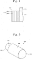
- FIG. 4 is an enlarged view illustrating an exemplary embodiment of a band pass filter of FIG. 3 .
- the light guide part includes the first light guide unit 310 and the second light guide unit 320 sequentially in a direction in which light is emitted from the first light guide unit 310.
- Each of the first light guide unit 310 and the second light guide unit 320 includes the light guide plates 311 and 321 overlapping at least the display area 140 of the display panel 100, the plurality of light sources 312 and 322 emitting light onto the light guide plates 311 and 321, and the band pass filters 313 and 323 between the light guide plates 311 and 321 and the light sources 312 and 322, respectively.
- Each of the light guide plates 311 and 321 includes a light emission surface through which light supplied from the light sources 312 and 322 is emitted toward the display panel 100, a bottom surface facing the light emission surface, and side surfaces connecting the light emission surface to the bottom surface.
- each of the light emission surface and the bottom surface may have various shapes.
- the number of side surfaces may be determined by a shape of each of the light emission surface and the bottom surface. In one embodiment, for example, each of the light emission surface and the bottom surface may have a square shape.
- the light guide plates 311 and 321 may have four side surfaces.
- each of the light guide plates 311 and 321 may include polycarbonate ("PC"). Also, the light guide plates 311 and 321 may further include light diffusion patterns 314 and 324 on the light emission surfaces, respectively. The light diffusion patterns 314 and 324 diffuse the light emitted from the light emission surface.
- PC polycarbonate
- the light guide plates 311 and 321 may further include light diffusion patterns 314 and 324 on the light emission surfaces, respectively. The light diffusion patterns 314 and 324 diffuse the light emitted from the light emission surface.
- the light sources 312 and 322 emit light onto at least one of the side surfaces of the light guide plates 311 and 321.
- the light is used for displaying an image on the display panel 100.
- the light emitted from each of the light sources 312 and 322 is supplied into the light guide plates 311 and 321 through the band pass filters 313 and 323.
- the light sources 312 and 322 may be mounted on a printed circuit board (not shown) in a package form.
- Each of the light sources 312 and 322 may be a light emitting diode.
- the light sources 312 of the first light guide unit 310 are coplanar with the light guide plate 311.
- the light sources 322 of the second light guide unit 320 are coplanar with the light guide plate 321.
- the band pass filters 313 and 323 transmit a portion of the light emitted from the light sources 312 and 322 to supply the transmitted light to the light guide plates 311 and 321. Also, the band pass filters 313 and 323 selectively reflect the rest of the emitted light.
- each of the band pass filters 313 and 323 may include a plurality of filter units 315 in which a plurality of films having reflective indexes different from each other are stacked.
- each of the filter units 315 includes first and second films 315a and 315b including a polymer material.
- the second film 315b is in a direction in which light is emitted from the first film 315a.
- the first film 315a may include polyethylene naphthalate (“PEN").
- the second film 315b may include polystyrene ("PS").
- the first film 315a and the second film 315b reflect light having a portion of a wavelength of light emitted from the light sources 312 and 322, e.g., at least one light of red, green, and blue light.
- the wavelengths reflected by the first and second films 315a and 315b may be determined according to thicknesses of each of the first and second films 315a and 315b.
- the thicknesses of the first and second films 315a and 315b are expressed as following Equation (1).
- n A * d A n B * d B
- n is a positive number greater than 0
- n A denotes a refractive index of the second film 315b
- d A denotes a thickness of the second film 315b
- n B denotes a refractive index of the first film 315a
- d B denotes a thickness of the first film 315a.
- the PS used for the second film 315b may have a refractive index of about 1.52
- the PEN used for the first film 315a may have a refractive index of about 1.85.
- the following Table 1 shows thicknesses of the first and second films 313a and 315b for reflecting centroid wavelengths of red, green, and blue light according to Equation (1).
- the first film 315a includes PEN
- the first film 315a has a refractive index of about 1.85
- the second film 315b has a refractive index of about 1.52.
- the filter unit 315 when the filter unit 315 includes the first and second films 315a and 315b, it is seen that thicknesses of the first and second films 315a and 315b are adjusted to reflect centroid wavelengths of two light of the red, green, and blue light and transmit the other light.
- the filter unit 315 reflects light having the centroid wavelengths of 630 nm and 540 nm of the red and green light, respectively, and transmit the other remaining light.
- the filter unit 315 includes an additional film (not shown) except the first and second films 315a and 315b, the additional film may further reflect light having a specific wavelength except the red and green light.
- the filter units 315 of the band pass filters 313 and 323 included in the first and second light guide units 310 and 320 have constitutions (e.g., materials and/or dimensions) different from each other, the filter units 315 reflect light having wavelengths different from each other.
- the band pass filters 313 and 323 should reflect about 70% or more of light, except light to be transmitted.
- reflectances of the band pass filters 313 and 323 are expressed as following Equation (2).
- R max n m / n s ⁇ n B / n A 2 N n m / n s + n B / n A 2 N 2
- N is the number of filter units 315 of the band pass filters 313 and 323
- n m denotes a refractive index of the atmosphere
- n s denotes refractive indexes of the light guide plates 311 and 321.
- the first film 315a includes PEN
- the first film 315a has a refractive index of about 1.85
- the second film 315b includes PS
- the second film 315b has a refractive index of about 1.52.
- the atmosphere has a refractive index of about 1.
- each of the light guide plates 311 and 321 includes PC
- each of the light guide plates 311 and 321 has a refractive index of about 1.59.
- Reflective index in centroid wavelength of each of band pass filters The number of filter unit 1 2 3 4 5 6 Refractive index 16.3% 30.7% 45.6% 59.1% 70.2% 78.8%
- the refractive index is increased as the number of filter units 315 of the band pass filters 313 and 323 is increased. Specifically, when the band pass filters 313 and 323 include five filter units 315 or more, it is seen that the refractive index is above about 70%.
- the band pass filters 313 and 323 may reflect about 70% or more of light, except light to be transmitted.
- the band pass filters 313 and 323 may selectively reflect light to transmit only light having a desired wavelength.
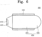
- FIG. 5 is a perspective view of an exemplary embodiment of a light source used in the display device of FIG. 1 and FIG. 6 is a cross-sectional view illustrating the light source of FIG. 5 .
- a light source 600 includes a light emitting diode (“LED") chip 610, a molding part 620 encapsulating the LED chip 610, and a lens part 630 collecting light generated from the LED chip 610. Also, the light source 600 may have a light emitting angle of about -15 degrees to about 15 degrees with respect to a center of the LED chip 610. This is done because the light source 600 is applied to the display device 500 to minimize light leaking in case where light is emitted onto the light guide plates 311 and 321.
- LED light emitting diode
- the LED chip 610 is a kind of p-n junction semiconductor in which electrons and holes are combined with each other to emit light. That is, the LED chip 610 is one of semiconductor devices in which a current flows to form a carrier including a small number of electrons and holes, and light is emitted using energy emitted when the electrons and holes are recombined with each other. Also, the LED chip 610 may be mounted on a lead frame (not shown) and electrically connected to a printed circuit board (not shown).
- the molding part 620 encapsulates the LED chip 610 to isolate the LED chip 610 from an external environment.
- the molding part 620 may have a cone shape in which an area of a surface on which the LED chip 610 is seated is less than that opposite to the surface.
- the lens part 630 may be on a surface of the molding part 620 on a path of light emitted from the LED chip 610, e.g., a surface opposite to a surface on which the LED chip 610 is seated on the molding part 620.
- the lens part 630 includes a light guide part 631 for guiding light emitted from the LED chip 610 to transmit the molding part 620, and a light collection part 632 at a front end of the light guide part 631 through which the light is emitted to collect the light.
- the light guide part 631 may have a cylindrical shape due to the molding part 620.
- the light collection part 632 may have a dome shape.
- the light guide part 631 may have a length of about 2 millimeters (mm) to about 6 mm, and a diameter of about 3 mm to about 5 mm. This is done for a reason that the light guide part 631 effectively guides the light emitted from the LED chip 610.
- Each of the molding part 620 and the lens part 630 has light transmission with respect to air and moisture.
- Each of the molding part 620 and the lens part 630 includes a material having superior light transmission.
- the material having the superior light transmission may be one selected from a group consisting of glass and resin.
- the resin may be one selected from a group consisting of a silicon resin, an epoxy resin, an acrylic resin, a urethane resin, a photoresist, and equivalents thereof.
- the light source 600 may further include a reflective member 640 surrounding the light guide part 631 to reflect the light leaking through the light guide part 631 of the lens part 630 in the light emitted from the LED chip 610, thereby increasing light efficiency of the light source 600.
- a reflective member 640 surrounding the light guide part 631 to reflect the light leaking through the light guide part 631 of the lens part 630 in the light emitted from the LED chip 610, thereby increasing light efficiency of the light source 600.
- more light in the light emitted from the LED chip 610 may be emitted onto the light guide plates 311 and 321.
- the backlight unit separates light having a desired wavelength to provide the separated light toward the display panel.
- a 3D image display device including the backlight unit may reduce or effectively prevent deterioration of a quality of the 3D image due to the mixture of left and right eye images.
Landscapes
- Physics & Mathematics (AREA)
- General Physics & Mathematics (AREA)
- Optics & Photonics (AREA)
- Nonlinear Science (AREA)
- Crystallography & Structural Chemistry (AREA)
- Mathematical Physics (AREA)
- Chemical & Material Sciences (AREA)
- Engineering & Computer Science (AREA)
- Signal Processing (AREA)
- General Engineering & Computer Science (AREA)
- Multimedia (AREA)
- Planar Illumination Modules (AREA)
- Light Guides In General And Applications Therefor (AREA)
Applications Claiming Priority (1)
| Application Number | Priority Date | Filing Date | Title |
|---|---|---|---|
| KR1020110026565A KR101780420B1 (ko) | 2011-03-24 | 2011-03-24 | 백라이트 유닛 및 이를 구비하는 입체 영상 표시 장치 |
Publications (2)
| Publication Number | Publication Date |
|---|---|
| EP2503367A1 EP2503367A1 (en) | 2012-09-26 |
| EP2503367B1 true EP2503367B1 (en) | 2016-04-27 |
Family
ID=46027538
Family Applications (1)
| Application Number | Title | Priority Date | Filing Date |
|---|---|---|---|
| EP12157655.7A Not-in-force EP2503367B1 (en) | 2011-03-24 | 2012-03-01 | Backlight unit and three-dimensional image display device having the same |
Country Status (5)
| Country | Link |
|---|---|
| US (1) | US8608361B2 (zh) |
| EP (1) | EP2503367B1 (zh) |
| JP (1) | JP5985221B2 (zh) |
| KR (1) | KR101780420B1 (zh) |
| CN (1) | CN102691931B (zh) |
Families Citing this family (7)
| Publication number | Priority date | Publication date | Assignee | Title |
|---|---|---|---|---|
| JP5974987B2 (ja) * | 2013-06-20 | 2016-08-23 | 株式会社デンソー | ヘッドアップディスプレイ装置、およびヘッドアップディスプレイ装置に用いられる照明装置 |
| CN104075186B (zh) * | 2014-06-16 | 2017-05-24 | 京东方科技集团股份有限公司 | 一种背光源及显示装置 |
| CN105700239A (zh) | 2016-04-22 | 2016-06-22 | 深圳市华星光电技术有限公司 | 背光模组及显示装置 |
| WO2018080464A1 (en) * | 2016-10-26 | 2018-05-03 | Hewlett-Packard Development Company, L.P. | Display panel illumination |
| TWI620959B (zh) * | 2017-04-25 | 2018-04-11 | 台達電子工業股份有限公司 | 立體顯示裝置 |
| CN108983488B (zh) * | 2017-06-01 | 2021-04-20 | 台达电子工业股份有限公司 | 背光模块及显示设备 |
| EP3765896A1 (en) | 2018-03-13 | 2021-01-20 | Apple Inc. | Displays with direct-lit backlight units |
Family Cites Families (24)
| Publication number | Priority date | Publication date | Assignee | Title |
|---|---|---|---|---|
| EP1213773B1 (en) * | 1999-07-26 | 2009-12-16 | Labosphere Institute | Bulk lens, light emitting body, lighting device and optical information system |
| JP3300778B2 (ja) * | 1999-10-05 | 2002-07-08 | ラボ・スフィア株式会社 | 発光体 |
| JP3585781B2 (ja) | 1999-08-31 | 2004-11-04 | 株式会社東芝 | 立体表示装置 |
| RU2001125705A (ru) * | 2001-02-23 | 2004-01-10 | Валерий Николаевич Бурцев (UA) | Устройство для демонстрации информации |
| US7040794B2 (en) | 2001-07-12 | 2006-05-09 | Northrop Grumman Corporation | Programmable multi-color backlight for a liquid crystal display |
| JP2003255344A (ja) | 2002-03-05 | 2003-09-10 | Citizen Electronics Co Ltd | カラー液晶表示装置のフロントライト |
| US7046320B2 (en) | 2002-03-14 | 2006-05-16 | Nitto Denko Corporation | Optical element and surface light source device using the same, as well as liquid crystal display |
| KR20040008955A (ko) | 2002-07-19 | 2004-01-31 | (주)아녹시스 | 삼차원 입체 영상 표시 장치 |
| KR100552589B1 (ko) * | 2005-10-26 | 2006-02-16 | 화우테크놀러지 주식회사 | 즉석맞춤이 용이한 백라이트 유니트 |
| JP4577229B2 (ja) | 2006-02-16 | 2010-11-10 | 日本電気株式会社 | バックライト装置及び液晶表示装置 |
| TWI321662B (en) | 2006-05-22 | 2010-03-11 | Young Optics Inc | Illumination system |
| US7317182B2 (en) * | 2006-05-24 | 2008-01-08 | 3M Innovative Properties Company | Backlight wedge with encapsulated light source |
| KR101243790B1 (ko) * | 2006-06-26 | 2013-03-18 | 엘지디스플레이 주식회사 | 입체 영상표시장치 |
| JP2008117730A (ja) | 2006-11-08 | 2008-05-22 | Enplas Corp | 面光源装置及びこれを備えた表示装置 |
| JP2008268398A (ja) | 2007-04-18 | 2008-11-06 | Seiko Epson Corp | 表示装置および電子機器 |
| JP2009104941A (ja) * | 2007-10-24 | 2009-05-14 | Seiko Instruments Inc | 照明装置、及び、表示装置 |
| JP2008287180A (ja) * | 2007-05-21 | 2008-11-27 | Toshiba Matsushita Display Technology Co Ltd | 液晶表示装置 |
| KR101365449B1 (ko) | 2007-06-14 | 2014-02-19 | 삼성전자주식회사 | 입체 영상 디스플레이 장치 |
| US8052320B2 (en) | 2008-02-28 | 2011-11-08 | Sharp Kabushiki Kaisha | Backlight device, display device and television receiver |
| CN101556403B (zh) * | 2008-04-10 | 2011-01-05 | 乐金显示有限公司 | 液晶显示设备 |
| JP2010123295A (ja) * | 2008-11-17 | 2010-06-03 | Nanocreate Co Ltd | 照明ユニットと同ユニットを用いた照明装置 |
| US9322973B2 (en) | 2009-07-16 | 2016-04-26 | Koninklijke Philips N.V. | Lighting device with light sources positioned near the bottom surface of a waveguide |
| KR101110136B1 (ko) | 2009-09-08 | 2012-01-31 | 주식회사 케이피엠테크 | 습식 피부미용팩용 전류인가장치 |
| US9028123B2 (en) * | 2010-04-16 | 2015-05-12 | Flex Lighting Ii, Llc | Display illumination device with a film-based lightguide having stacked incident surfaces |
-
2011
- 2011-03-24 KR KR1020110026565A patent/KR101780420B1/ko active IP Right Grant
-
2012
- 2012-01-17 US US13/351,592 patent/US8608361B2/en not_active Expired - Fee Related
- 2012-03-01 EP EP12157655.7A patent/EP2503367B1/en not_active Not-in-force
- 2012-03-22 CN CN201210078677.8A patent/CN102691931B/zh not_active Expired - Fee Related
- 2012-03-23 JP JP2012068137A patent/JP5985221B2/ja not_active Expired - Fee Related
Also Published As
| Publication number | Publication date |
|---|---|
| JP2012204346A (ja) | 2012-10-22 |
| KR101780420B1 (ko) | 2017-09-22 |
| EP2503367A1 (en) | 2012-09-26 |
| CN102691931B (zh) | 2016-09-14 |
| US8608361B2 (en) | 2013-12-17 |
| US20120243086A1 (en) | 2012-09-27 |
| CN102691931A (zh) | 2012-09-26 |
| JP5985221B2 (ja) | 2016-09-06 |
| KR20120109078A (ko) | 2012-10-08 |
Similar Documents
| Publication | Publication Date | Title |
|---|---|---|
| EP2503367B1 (en) | Backlight unit and three-dimensional image display device having the same | |
| US9651825B2 (en) | Liquid crystal lens display device with light shield structure | |
| KR101286095B1 (ko) | 액정표시장치용 일체형 멀티집광시트 | |
| CN114730044A (zh) | 定向照明设备和隐私显示器 | |
| US20170192301A1 (en) | Display device | |
| US8810752B2 (en) | Thin backlight system and liquid crystal display device using the same | |
| US20150301266A1 (en) | Lighting device and display device | |
| CN104456284A (zh) | 背光组件及其制造方法以及具有该背光组件的显示装置 | |
| US20150338675A1 (en) | Color filter and preparation method thereof, and display device | |
| CN111965889A (zh) | 背光单元及包括其的显示装置 | |
| KR102039362B1 (ko) | 액정디스플레이를 포함하는 모바일 장치 | |
| KR102566258B1 (ko) | 파장 선택형 투과 필터부재 및 그를 포함하는 액정 표시패널 | |
| US9910205B2 (en) | Light-emitting device and display device | |
| JP5263751B2 (ja) | 一画面表示装置 | |
| US8976304B2 (en) | Display device and television receiver device | |
| KR101854697B1 (ko) | 백라이트 유닛 및 이를 포함하는 액정표시장치모듈 | |
| JP4436752B2 (ja) | 光源装置および液晶表示装置 | |
| KR102571687B1 (ko) | 프리즘 시트 및 이를 구비한 백 라이트 유닛과 액정 표시장치 | |
| US10802206B2 (en) | Curved display device | |
| KR20130071926A (ko) | 확산시트 및 이를 포함하는 백라이트 유닛, 액정표시장치모듈 | |
| JP6861050B2 (ja) | 液晶表示装置 | |
| US9971199B2 (en) | Liquid crystal display panel and liquid crystal display device | |
| KR102289200B1 (ko) | 액정표시장치 | |
| KR20120072888A (ko) | 백라이트 유닛 및 액정표시장치 | |
| US20120242917A1 (en) | Shutter panel and display device including the same |
Legal Events
| Date | Code | Title | Description |
|---|---|---|---|
| PUAI | Public reference made under article 153(3) epc to a published international application that has entered the european phase |
Free format text: ORIGINAL CODE: 0009012 |
|
| 17P | Request for examination filed |
Effective date: 20120326 |
|
| AK | Designated contracting states |
Kind code of ref document: A1 Designated state(s): AL AT BE BG CH CY CZ DE DK EE ES FI FR GB GR HR HU IE IS IT LI LT LU LV MC MK MT NL NO PL PT RO RS SE SI SK SM TR |
|
| AX | Request for extension of the european patent |
Extension state: BA ME |
|
| RAP1 | Party data changed (applicant data changed or rights of an application transferred) |
Owner name: SAMSUNG DISPLAY CO., LTD. |
|
| RAP1 | Party data changed (applicant data changed or rights of an application transferred) |
Owner name: SAMSUNG DISPLAY CO., LTD. |
|
| GRAP | Despatch of communication of intention to grant a patent |
Free format text: ORIGINAL CODE: EPIDOSNIGR1 |
|
| INTG | Intention to grant announced |
Effective date: 20151002 |
|
| GRAS | Grant fee paid |
Free format text: ORIGINAL CODE: EPIDOSNIGR3 |
|
| GRAA | (expected) grant |
Free format text: ORIGINAL CODE: 0009210 |
|
| AK | Designated contracting states |
Kind code of ref document: B1 Designated state(s): AL AT BE BG CH CY CZ DE DK EE ES FI FR GB GR HR HU IE IS IT LI LT LU LV MC MK MT NL NO PL PT RO RS SE SI SK SM TR |
|
| REG | Reference to a national code |
Ref country code: GB Ref legal event code: FG4D |
|
| REG | Reference to a national code |
Ref country code: CH Ref legal event code: EP |
|
| REG | Reference to a national code |
Ref country code: AT Ref legal event code: REF Ref document number: 795397 Country of ref document: AT Kind code of ref document: T Effective date: 20160515 |
|
| REG | Reference to a national code |
Ref country code: IE Ref legal event code: FG4D |
|
| REG | Reference to a national code |
Ref country code: DE Ref legal event code: R096 Ref document number: 602012017525 Country of ref document: DE |
|
| REG | Reference to a national code |
Ref country code: LT Ref legal event code: MG4D |
|
| REG | Reference to a national code |
Ref country code: NL Ref legal event code: MP Effective date: 20160427 |
|
| REG | Reference to a national code |
Ref country code: AT Ref legal event code: MK05 Ref document number: 795397 Country of ref document: AT Kind code of ref document: T Effective date: 20160427 |
|
| PG25 | Lapsed in a contracting state [announced via postgrant information from national office to epo] |
Ref country code: NL Free format text: LAPSE BECAUSE OF FAILURE TO SUBMIT A TRANSLATION OF THE DESCRIPTION OR TO PAY THE FEE WITHIN THE PRESCRIBED TIME-LIMIT Effective date: 20160427 |
|
| PG25 | Lapsed in a contracting state [announced via postgrant information from national office to epo] |
Ref country code: FI Free format text: LAPSE BECAUSE OF FAILURE TO SUBMIT A TRANSLATION OF THE DESCRIPTION OR TO PAY THE FEE WITHIN THE PRESCRIBED TIME-LIMIT Effective date: 20160427 Ref country code: LT Free format text: LAPSE BECAUSE OF FAILURE TO SUBMIT A TRANSLATION OF THE DESCRIPTION OR TO PAY THE FEE WITHIN THE PRESCRIBED TIME-LIMIT Effective date: 20160427 Ref country code: PL Free format text: LAPSE BECAUSE OF FAILURE TO SUBMIT A TRANSLATION OF THE DESCRIPTION OR TO PAY THE FEE WITHIN THE PRESCRIBED TIME-LIMIT Effective date: 20160427 Ref country code: NO Free format text: LAPSE BECAUSE OF FAILURE TO SUBMIT A TRANSLATION OF THE DESCRIPTION OR TO PAY THE FEE WITHIN THE PRESCRIBED TIME-LIMIT Effective date: 20160727 |
|
| PG25 | Lapsed in a contracting state [announced via postgrant information from national office to epo] |
Ref country code: ES Free format text: LAPSE BECAUSE OF FAILURE TO SUBMIT A TRANSLATION OF THE DESCRIPTION OR TO PAY THE FEE WITHIN THE PRESCRIBED TIME-LIMIT Effective date: 20160427 Ref country code: RS Free format text: LAPSE BECAUSE OF FAILURE TO SUBMIT A TRANSLATION OF THE DESCRIPTION OR TO PAY THE FEE WITHIN THE PRESCRIBED TIME-LIMIT Effective date: 20160427 Ref country code: SE Free format text: LAPSE BECAUSE OF FAILURE TO SUBMIT A TRANSLATION OF THE DESCRIPTION OR TO PAY THE FEE WITHIN THE PRESCRIBED TIME-LIMIT Effective date: 20160427 Ref country code: GR Free format text: LAPSE BECAUSE OF FAILURE TO SUBMIT A TRANSLATION OF THE DESCRIPTION OR TO PAY THE FEE WITHIN THE PRESCRIBED TIME-LIMIT Effective date: 20160728 Ref country code: PT Free format text: LAPSE BECAUSE OF FAILURE TO SUBMIT A TRANSLATION OF THE DESCRIPTION OR TO PAY THE FEE WITHIN THE PRESCRIBED TIME-LIMIT Effective date: 20160829 Ref country code: AT Free format text: LAPSE BECAUSE OF FAILURE TO SUBMIT A TRANSLATION OF THE DESCRIPTION OR TO PAY THE FEE WITHIN THE PRESCRIBED TIME-LIMIT Effective date: 20160427 Ref country code: LV Free format text: LAPSE BECAUSE OF FAILURE TO SUBMIT A TRANSLATION OF THE DESCRIPTION OR TO PAY THE FEE WITHIN THE PRESCRIBED TIME-LIMIT Effective date: 20160427 Ref country code: HR Free format text: LAPSE BECAUSE OF FAILURE TO SUBMIT A TRANSLATION OF THE DESCRIPTION OR TO PAY THE FEE WITHIN THE PRESCRIBED TIME-LIMIT Effective date: 20160427 |
|
| PG25 | Lapsed in a contracting state [announced via postgrant information from national office to epo] |
Ref country code: IT Free format text: LAPSE BECAUSE OF FAILURE TO SUBMIT A TRANSLATION OF THE DESCRIPTION OR TO PAY THE FEE WITHIN THE PRESCRIBED TIME-LIMIT Effective date: 20160427 Ref country code: BE Free format text: LAPSE BECAUSE OF FAILURE TO SUBMIT A TRANSLATION OF THE DESCRIPTION OR TO PAY THE FEE WITHIN THE PRESCRIBED TIME-LIMIT Effective date: 20160427 |
|
| REG | Reference to a national code |
Ref country code: DE Ref legal event code: R097 Ref document number: 602012017525 Country of ref document: DE |
|
| PG25 | Lapsed in a contracting state [announced via postgrant information from national office to epo] |
Ref country code: EE Free format text: LAPSE BECAUSE OF FAILURE TO SUBMIT A TRANSLATION OF THE DESCRIPTION OR TO PAY THE FEE WITHIN THE PRESCRIBED TIME-LIMIT Effective date: 20160427 Ref country code: CZ Free format text: LAPSE BECAUSE OF FAILURE TO SUBMIT A TRANSLATION OF THE DESCRIPTION OR TO PAY THE FEE WITHIN THE PRESCRIBED TIME-LIMIT Effective date: 20160427 Ref country code: SK Free format text: LAPSE BECAUSE OF FAILURE TO SUBMIT A TRANSLATION OF THE DESCRIPTION OR TO PAY THE FEE WITHIN THE PRESCRIBED TIME-LIMIT Effective date: 20160427 Ref country code: RO Free format text: LAPSE BECAUSE OF FAILURE TO SUBMIT A TRANSLATION OF THE DESCRIPTION OR TO PAY THE FEE WITHIN THE PRESCRIBED TIME-LIMIT Effective date: 20160427 Ref country code: DK Free format text: LAPSE BECAUSE OF FAILURE TO SUBMIT A TRANSLATION OF THE DESCRIPTION OR TO PAY THE FEE WITHIN THE PRESCRIBED TIME-LIMIT Effective date: 20160427 |
|
| REG | Reference to a national code |
Ref country code: FR Ref legal event code: PLFP Year of fee payment: 6 |
|
| PG25 | Lapsed in a contracting state [announced via postgrant information from national office to epo] |
Ref country code: SM Free format text: LAPSE BECAUSE OF FAILURE TO SUBMIT A TRANSLATION OF THE DESCRIPTION OR TO PAY THE FEE WITHIN THE PRESCRIBED TIME-LIMIT Effective date: 20160427 |
|
| PLBE | No opposition filed within time limit |
Free format text: ORIGINAL CODE: 0009261 |
|
| STAA | Information on the status of an ep patent application or granted ep patent |
Free format text: STATUS: NO OPPOSITION FILED WITHIN TIME LIMIT |
|
| 26N | No opposition filed |
Effective date: 20170130 |
|
| PG25 | Lapsed in a contracting state [announced via postgrant information from national office to epo] |
Ref country code: SI Free format text: LAPSE BECAUSE OF FAILURE TO SUBMIT A TRANSLATION OF THE DESCRIPTION OR TO PAY THE FEE WITHIN THE PRESCRIBED TIME-LIMIT Effective date: 20160427 |
|
| REG | Reference to a national code |
Ref country code: CH Ref legal event code: PL |
|
| PG25 | Lapsed in a contracting state [announced via postgrant information from national office to epo] |
Ref country code: MC Free format text: LAPSE BECAUSE OF FAILURE TO SUBMIT A TRANSLATION OF THE DESCRIPTION OR TO PAY THE FEE WITHIN THE PRESCRIBED TIME-LIMIT Effective date: 20160427 |
|
| REG | Reference to a national code |
Ref country code: IE Ref legal event code: MM4A |
|
| PG25 | Lapsed in a contracting state [announced via postgrant information from national office to epo] |
Ref country code: LU Free format text: LAPSE BECAUSE OF NON-PAYMENT OF DUE FEES Effective date: 20170301 |
|
| REG | Reference to a national code |
Ref country code: FR Ref legal event code: PLFP Year of fee payment: 7 |
|
| PG25 | Lapsed in a contracting state [announced via postgrant information from national office to epo] |
Ref country code: IE Free format text: LAPSE BECAUSE OF NON-PAYMENT OF DUE FEES Effective date: 20170301 Ref country code: CH Free format text: LAPSE BECAUSE OF NON-PAYMENT OF DUE FEES Effective date: 20170331 Ref country code: LI Free format text: LAPSE BECAUSE OF NON-PAYMENT OF DUE FEES Effective date: 20170331 |
|
| PG25 | Lapsed in a contracting state [announced via postgrant information from national office to epo] |
Ref country code: MT Free format text: LAPSE BECAUSE OF NON-PAYMENT OF DUE FEES Effective date: 20170301 |
|
| PG25 | Lapsed in a contracting state [announced via postgrant information from national office to epo] |
Ref country code: AL Free format text: LAPSE BECAUSE OF FAILURE TO SUBMIT A TRANSLATION OF THE DESCRIPTION OR TO PAY THE FEE WITHIN THE PRESCRIBED TIME-LIMIT Effective date: 20160427 |
|
| PG25 | Lapsed in a contracting state [announced via postgrant information from national office to epo] |
Ref country code: HU Free format text: LAPSE BECAUSE OF FAILURE TO SUBMIT A TRANSLATION OF THE DESCRIPTION OR TO PAY THE FEE WITHIN THE PRESCRIBED TIME-LIMIT; INVALID AB INITIO Effective date: 20120301 |
|
| PG25 | Lapsed in a contracting state [announced via postgrant information from national office to epo] |
Ref country code: BG Free format text: LAPSE BECAUSE OF FAILURE TO SUBMIT A TRANSLATION OF THE DESCRIPTION OR TO PAY THE FEE WITHIN THE PRESCRIBED TIME-LIMIT Effective date: 20160427 |
|
| PG25 | Lapsed in a contracting state [announced via postgrant information from national office to epo] |
Ref country code: CY Free format text: LAPSE BECAUSE OF NON-PAYMENT OF DUE FEES Effective date: 20160427 |
|
| PG25 | Lapsed in a contracting state [announced via postgrant information from national office to epo] |
Ref country code: MK Free format text: LAPSE BECAUSE OF FAILURE TO SUBMIT A TRANSLATION OF THE DESCRIPTION OR TO PAY THE FEE WITHIN THE PRESCRIBED TIME-LIMIT Effective date: 20160427 |
|
| PG25 | Lapsed in a contracting state [announced via postgrant information from national office to epo] |
Ref country code: TR Free format text: LAPSE BECAUSE OF FAILURE TO SUBMIT A TRANSLATION OF THE DESCRIPTION OR TO PAY THE FEE WITHIN THE PRESCRIBED TIME-LIMIT Effective date: 20160427 |
|
| PGFP | Annual fee paid to national office [announced via postgrant information from national office to epo] |
Ref country code: DE Payment date: 20200220 Year of fee payment: 9 Ref country code: GB Payment date: 20200225 Year of fee payment: 9 |
|
| PGFP | Annual fee paid to national office [announced via postgrant information from national office to epo] |
Ref country code: FR Payment date: 20200221 Year of fee payment: 9 |
|
| PG25 | Lapsed in a contracting state [announced via postgrant information from national office to epo] |
Ref country code: IS Free format text: LAPSE BECAUSE OF FAILURE TO SUBMIT A TRANSLATION OF THE DESCRIPTION OR TO PAY THE FEE WITHIN THE PRESCRIBED TIME-LIMIT Effective date: 20160827 |
|
| REG | Reference to a national code |
Ref country code: DE Ref legal event code: R119 Ref document number: 602012017525 Country of ref document: DE |
|
| GBPC | Gb: european patent ceased through non-payment of renewal fee |
Effective date: 20210301 |
|
| PG25 | Lapsed in a contracting state [announced via postgrant information from national office to epo] |
Ref country code: GB Free format text: LAPSE BECAUSE OF NON-PAYMENT OF DUE FEES Effective date: 20210301 Ref country code: FR Free format text: LAPSE BECAUSE OF NON-PAYMENT OF DUE FEES Effective date: 20210331 Ref country code: DE Free format text: LAPSE BECAUSE OF NON-PAYMENT OF DUE FEES Effective date: 20211001 |