EP2503357A1 - Vehicular ranging system and method of operation - Google Patents
Vehicular ranging system and method of operation Download PDFInfo
- Publication number
- EP2503357A1 EP2503357A1 EP12160948A EP12160948A EP2503357A1 EP 2503357 A1 EP2503357 A1 EP 2503357A1 EP 12160948 A EP12160948 A EP 12160948A EP 12160948 A EP12160948 A EP 12160948A EP 2503357 A1 EP2503357 A1 EP 2503357A1
- Authority
- EP
- European Patent Office
- Prior art keywords
- range
- long
- short
- range sensor
- view
- Prior art date
- Legal status (The legal status is an assumption and is not a legal conclusion. Google has not performed a legal analysis and makes no representation as to the accuracy of the status listed.)
- Granted
Links
Images


Classifications
-
- B—PERFORMING OPERATIONS; TRANSPORTING
- B60—VEHICLES IN GENERAL
- B60W—CONJOINT CONTROL OF VEHICLE SUB-UNITS OF DIFFERENT TYPE OR DIFFERENT FUNCTION; CONTROL SYSTEMS SPECIALLY ADAPTED FOR HYBRID VEHICLES; ROAD VEHICLE DRIVE CONTROL SYSTEMS FOR PURPOSES NOT RELATED TO THE CONTROL OF A PARTICULAR SUB-UNIT
- B60W40/00—Estimation or calculation of non-directly measurable driving parameters for road vehicle drive control systems not related to the control of a particular sub unit, e.g. by using mathematical models
- B60W40/02—Estimation or calculation of non-directly measurable driving parameters for road vehicle drive control systems not related to the control of a particular sub unit, e.g. by using mathematical models related to ambient conditions
-
- G—PHYSICS
- G01—MEASURING; TESTING
- G01S—RADIO DIRECTION-FINDING; RADIO NAVIGATION; DETERMINING DISTANCE OR VELOCITY BY USE OF RADIO WAVES; LOCATING OR PRESENCE-DETECTING BY USE OF THE REFLECTION OR RERADIATION OF RADIO WAVES; ANALOGOUS ARRANGEMENTS USING OTHER WAVES
- G01S7/00—Details of systems according to groups G01S13/00, G01S15/00, G01S17/00
- G01S7/48—Details of systems according to groups G01S13/00, G01S15/00, G01S17/00 of systems according to group G01S17/00
- G01S7/483—Details of pulse systems
- G01S7/486—Receivers
-
- B—PERFORMING OPERATIONS; TRANSPORTING
- B60—VEHICLES IN GENERAL
- B60R—VEHICLES, VEHICLE FITTINGS, OR VEHICLE PARTS, NOT OTHERWISE PROVIDED FOR
- B60R1/00—Optical viewing arrangements; Real-time viewing arrangements for drivers or passengers using optical image capturing systems, e.g. cameras or video systems specially adapted for use in or on vehicles
-
- G—PHYSICS
- G01—MEASURING; TESTING
- G01S—RADIO DIRECTION-FINDING; RADIO NAVIGATION; DETERMINING DISTANCE OR VELOCITY BY USE OF RADIO WAVES; LOCATING OR PRESENCE-DETECTING BY USE OF THE REFLECTION OR RERADIATION OF RADIO WAVES; ANALOGOUS ARRANGEMENTS USING OTHER WAVES
- G01S17/00—Systems using the reflection or reradiation of electromagnetic waves other than radio waves, e.g. lidar systems
- G01S17/02—Systems using the reflection of electromagnetic waves other than radio waves
- G01S17/06—Systems determining position data of a target
-
- G—PHYSICS
- G01—MEASURING; TESTING
- G01S—RADIO DIRECTION-FINDING; RADIO NAVIGATION; DETERMINING DISTANCE OR VELOCITY BY USE OF RADIO WAVES; LOCATING OR PRESENCE-DETECTING BY USE OF THE REFLECTION OR RERADIATION OF RADIO WAVES; ANALOGOUS ARRANGEMENTS USING OTHER WAVES
- G01S17/00—Systems using the reflection or reradiation of electromagnetic waves other than radio waves, e.g. lidar systems
- G01S17/87—Combinations of systems using electromagnetic waves other than radio waves
-
- G—PHYSICS
- G01—MEASURING; TESTING
- G01S—RADIO DIRECTION-FINDING; RADIO NAVIGATION; DETERMINING DISTANCE OR VELOCITY BY USE OF RADIO WAVES; LOCATING OR PRESENCE-DETECTING BY USE OF THE REFLECTION OR RERADIATION OF RADIO WAVES; ANALOGOUS ARRANGEMENTS USING OTHER WAVES
- G01S17/00—Systems using the reflection or reradiation of electromagnetic waves other than radio waves, e.g. lidar systems
- G01S17/88—Lidar systems specially adapted for specific applications
- G01S17/93—Lidar systems specially adapted for specific applications for anti-collision purposes
- G01S17/931—Lidar systems specially adapted for specific applications for anti-collision purposes of land vehicles
Definitions
- the improvements generally relate to the field of vehicular perception systems for automotive vehicles, and more specifically relates to a vehicular object ranging system having both a short range sensor and a long range sensor.
- Vehicular perception systems have been in development for several years, notably in automotive applications. It is known to use active sensors in such systems, which include both an emitter and a detector.
- An example of active sensors is LIDAR (LIght Detection And Ranging) technology, where a light signal can be emitted by a LED (Light Emitting Diode) or laser emitter (such as laser diode), for instance, and is later received by an associated detector.
- LED Light Emitting Diode
- laser emitter such as laser diode
- a wider field of view was required at short range than at longer range.
- a combination of active sensors can be used instead of using a single active sensor with a wide field of view requirement to cover an entire range requirement.
- a shorter range sensor can be diffused over a wider field of view which can be required at shorter range, whereas a long range sensor can have its power concentrated over a narrower field of view to significantly reduce its power requirement compared to a sensor having the same range but a field of view meeting the shorter range field of view requirement.
- MTBF mean-time between failures
- this application describes a method of modulation of the sampling frequencies of two complementary obstacle detection and ranging subsystems in order to reduce the number of emitted laser pulses required for the operation of said subsystems, thus increasing the lifespan of the laser emitters of the subsystems.
- Each of the subsystems having complementary obstacle range capability in order to meet the requirements of different obstacle detection situations.
- a short-range and wide field-of-view object detection and ranging subsystem system is typically required for collision mitigation systems in low-speed driving situations (typically, urban "stop-and-go" collision mitigation applications.
- a long-range and narrow field-of-view object detection and ranging subsystem system is also typically required for collision mitigation systems in high-speed driving situations (typically, highway or high-speed collision mitigation applications).
- each of the subsystems can be considered exclusive in some driving situations.
- the sampling frequency of one of the subsystems can be reduced substantially (and in some cases, reduced to 0), while the frequency of the complementary subsystem is maintained at a normal operating frequency.
- the reduction of the sampling rate of the subsystems is expected to provide a reduction of the total pulses emitted by the laser sources of each subsystem.
- the number of laser pulses being one important factor in determining the MTBF of pulsed laser sources, the invention will increase the MTBF of each of the subsystems.
- the actual improvement on the MTBF of the laser-based subsystems will be dependent on other factors, such as the MTBF of all physical components of each subsystems as well as variations in the driving conditions in which the subsystems are used. Nonetheless, important improvement of the laser-based obstacle detection and ranging subsystems MTBF are expected.
- a method of operating a vehicular object ranging system having a long-range laser LIDAR system having a long-range field of view and a long-range depth, and a short-range laser LIDAR system having a short-range field of view overlapping and exceeding said long-range field of view and a short-range depth smaller than said long-range depth comprising operating one of said long-range sensor and said short-range sensor while simultaneously maintaining the other one of said long-range sensor and said short-range sensor in one of a reduced activation mode and an inactive mode.
- a method of operating a vehicular object ranging system having a long-range sensor having a long-range field of view and a short-range sensor having a short-range field of view overlapping and exceeding said long-range field of view and having an angular resolution capability comprising: operating the long-range sensor at a long-range sampling rate to generate at least one indication of one of an absence and a range of an object within said long-range field of view; operating the short-range sensor at a short-range sampling rate to generate at least one indication of one of an absence and a range of an object within said short-range field of view; and varying the sampling rate of one of the long-range sensor and the short-range sensor based on the at least one indication provided by the other one of the long-range sensor and the short-range sensor.
- a vehicular object ranging system having a housing containing a long-range sensor having a long-range field of view and a long-range depth and a short-range sensor having a short-range field of view overlapping and exceeding said long-range field of view and a short-range depth smaller than said long-range depth, and a control module having a function to operate one of said long-range sensor and said short-range sensor while simultaneously maintaining the other one of said long-range sensor and said short-range sensor in one of a reduced activation mode and an inactive mode.
- the depth signal can be combined to a color signal from a camera into a fused RGBD (Red, Green, Blue, Depth) or RGBID (Red, Green, Blue, Depth, Intensity) signal to become a power acquisition apparatus.
- RGBD Red, Green, Blue, Depth
- RGBID Red, Green, Blue, Depth, Intensity
- Figs. 1 to 3 are schematic views of a first example of a vehicular object ranging system
- Figs. 4 to 7 show different scenarios
- Fig. 8 is a block diagram of a proposed embodiment of a vehicular object ranging system
- Fig. 9 is a block diagram of an alternate embodiment
- Fig. 10 is a block diagram of an example of a complete system
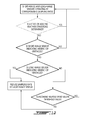
- Fig. 11 is a flow chart showing variation of the sampling rate of the long-range sensor based on the output of the short-range sensor.
- Fig. 12 is a flow chart showing variation of the sampling rate of the short-range sensor based on the output of the long-range sensor.
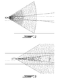
- Fig.1 shows an example of field of view and depth of view for an object ranging system of a vehicle 10, the object ranging system having two sensors subsystems, including a first sensor subsystem referred to as a short range sensor which has a short field of view 11 covering a horizontal angle ⁇ and a depth 12, and a second sensor subsystem referred to as a long range sensor having a long field of view 15 covering a narrower horizontal angle ⁇ but a greater depth 16.
- the two subsystems can be used independently for different road safety applications in this example.
- the short-range field of view 11 can satisfy the requirements of some low-speed collision avoidance applications, such as high-density traffic braking assistance systems for instance (examples of which are described later in the text), and can be adapted for the detection of some collision situations where the relative speed of the obstacle is relatively low, as in "cut-in" detection applications or lane change assistance applications (a cut-in scenario is shown in Fig. 1 ).
- the long range field of view 15 can be used for high-speed driving situations (such as on highways), to give sufficient reaction time to collision avoidance systems in high speed situations.
- the narrower field of view is selected to optimize usage of the system resources (such as emitter power or the angular resolution of detectors) to the region where obstacles are most likely to be detected in such driving situations.
- the output from one of the sensors can be used in determining an appropriate condition to reduce the sampling rate of the other sensor.
- both the short range sensor and the long range sensor are laser LIDAR subsystems having angular resolution capability.
- the short-range sensor field of view is more clearly shown in Fig. 2 as having emission and associated detection spanning a 60° field of view (i.e. 30° to each side in front of the vehicle), reaching a range of approximately 55 meters from the front of the vehicle, whereas the long-range sensor can be concentrated on an 11° field of view and can be used to sense 3 lanes wide in the range of between 50 and 150 meters.
- Alternative embodiments can have the short range sensor having a field of view between 40 and 80°, preferably between 50 and 70, and a range of 100 meters, preferably up to 70 meters, for instance and have the long range sensor having a field of view between 5 and 20°, preferably between 10 and 15, and a range of up to 200 meters, or up to 170 meters, for instance, for automotive applications.
- the short range lidar subsystem can have a 16x 1, 32X1 or similar horizontally oriented array of detectors each covering a given angular span in the field of view for example. In the embodiment shown in Fig. 2 , the individual angular span is of 1.8° for a 32X1 array.
- the long-range sensor can be linear mode FPA with configurations like 32 x 16 pixels concentrated on the narrower field of view.
- the angular resolution is optional especially for the long-range sensor. Having 32 X 16 type of FPA can be useful in the long range applications to determine the depth ( volume ) that can be translated detecting and understanding multiple vehicles if they are close proximity to each other.
- the angular resolution is optional and can be omitted in alternate embodiment, especially for the long range sensor.
- Fig. 3 a long-range subsystem having a 8X1 array is shown with each individual sensor coverin a 1.3° field of view.
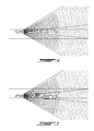
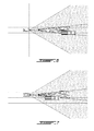
- the two sensors can provide indications of different scenarios. For instance, in Figs 2 and 3 , both sensors can provide an indication of absence of objects in the respective fields of view, which indication can be used to trigger a reduction in the sampling rate of the short range sensor, for instance.
- the short-range sensor can provide an indication that an object in the short range field of view, completely blocs the long-range field of view. This condition can trigger a reduction of the sampling rate of the long-range field of view, potentially down to zero, to thereby improve its mean-time between failure, for instance.
- vehicular ranging systems include sensors which operate at given sampling rates, such as laser emission sensors, LED based lidars, or radars. Lasers and LED's are particularly susceptible to premature failure when compared to radars.
- the sampling rates can be regular or irregular. In the case of regular sampling rates, the expression "frequency" is used.
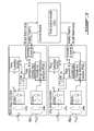
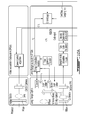
- Fig. 8 shows a functional block diagram of a proposed embodiment.
- This embodiment comprises a short-range (wide field of view) obstacle detection and ranging subsystem, a long-range (narrow field of view) obstacle detection and ranging subsystem and a control module.
- the short-range obstacle detection and ranging subsystem is composed of a laser emitter and accompanying optics and an optical detector with accompanying optics.
- the subsystem also contains a pulse generator used to periodically trigger the laser emitter in the generation of a pulse sequence, the periodicity of the pulse (or inversely, the related sampling frequency) of the pulse sequence being a controllable parameter.
- An obstacle and range detection module is used to interpret the optical detector input and translate it into actual identification of obstacles and range, providing identifiable characteristics of the obstacles (such as dimension) as a function of the capability of the detector, discussed further in the document. Additional support components, such as temperature monitoring and conditioning are also included in the subsystem.
- the subsystem contains a parameter and control module, used to obtain operation and control commands from the main control module and to ensure their proper application to the component modules of the subsystem.
- the detectors of the short-range obstacle detection and ranging subsystem is an arrayed detector, providing the capability to the subsystem of a fine angular resolution for obstacle detection within the field of view of the system. For example, using a linear array detector and a FOV of 60 degrees, the average coverage by detector "pixel" would be on average below 2 degrees.
- the long-range obstacle detection and ranging subsystem is configured in a similar fashion to the short-range, wide field of view obstacle detection and ranging subsystem.
- the differences between the two subsystems reside in the adaptations of the emitter and detector optics to the varying field of view, and in the use of different emitter wavelengths for each subsystem, with the subsequent adaptations of the emitter and detector optics and filters to the wavelength used by the subsystem.
- the long-range obstacle detection and ranging subsystem is able to provide the distance of the objects detected
- the long-range obstacle detection and ranging subsystems can also optionally provide angular position and angular dimensions similar to those provided by the short-range subsystem.
- the control module acquires, through communication with the parameter and control module of both subsystems, the obstacle identification of obstacles and range from both subsystems. Using rules (discussed further in the document), to assess the driving situation and determine the required usage of each of the subsystems, the Control Module instructs each of the subsystems on the recommended sampling frequency to be used.
- the pulse sequence generated by the pulse generator can be a single pulse. In other embodiments, the pulse sequence can be comprised of multiple pulses, evenly or unevenly spaced.
- the output beam can be diffused by a proper lens, in a way to cover an area of interest with a single pulse as opposed to scanning lasers for instance.
- the emitter and detector subsystems need not be based on laser emitters or optical receivers.
- the subsystems can be based on alternate obstacle detection and ranging technologies, such as radar or acoustic techniques. The nature of the subsystem does not impact on the potential for improvement on the MTBF using the sampling frequency modulation described as part of this invention.
- the Control Module can implement hardware control of the sampling frequency of both subsystems in order to improve on the MTBF of the subsystem components as described below.
- the long-range subsystem sampling rate can be significantly reduced (and even shut down or placed in an other energy saving mode, if the embodiment permits).
- the sampling rate of the short-range subsystem can be kept at its maximal rate.
- a single obstacle detected by the short-range detection subsystem is determined to obscure completely the long range detection subsystem's field of view (as per Fig. 4 )
- the calculated width of each identified object can be cumulated with a margin of error equivalent to the angular resolution of the long-range detection subsystem on each side of the object.
- multiple obstacles detected by the short-range detection subsystem can be determined to obscure completely the long-range detection subsystem's field of view (as per Fig. 6 ) when the gap between obstacles is less than twice the angular resolution of the long-range detection subsystem.
- objects can be determined to exceed the long-range detection subsystem's field of view limits when they are within once the angular resolution of the long-range detection subsystem.
- the long-range detection subsystem should still operate, perhaps at a normal operation sampling rate.
- the sampling rate of the short range subsystem can be reduced to a factor determined by the safety margins established for the embodiment.
- both subsystems should be operated at maximum sampling frequency.
- the safety margin established by the embodiment can be proportional to vehicle speed, and detection range of the short-range subsystem with a set minimum threshold.
- a potential threat is the possibility of a head-on collision with an oncoming obstacle that is coming from outside the FOV of the long-range subsystem.
- the reduction in sampling rate can be determined to have only a marginal effect on the reaction time. For instance, using a 55 meter depth of view for the short-range detection system, and an impending head-on collision of 2 vehicles, each with an ego speed at 100 km/h. In this case, relative speed between vehicles is 55m/s. With a 100 Hz sampling rate, the distance a vehicle travels between samples is 0,5m, while, with a 10 Hz sampling rate, the distance a vehicle travels is 5,5 m. This amounts to less than 1/10 of a second difference between both sampling rates.
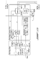
- Fig. 9 describes another proposed embodiment of the invention where only the emitter portions of the short-range and long-range subsystems are distinct.
- the receiver portion is common to both subsystems. This is accomplished by using emitters that use the same wavelength.
- the receiver optics is comprised of separate lenses to accommodate the different field of views, and the collimated beams at the receiver end are transmitted to a single optical receiver using optical devices to insert both beams in a single optical path.
- the pulse generator and conditioner module can alternately trigger each of the emitters sequentially, rather than simultaneously.
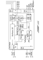
- Fig. 10 describes a proposed embodiment with complementary details pertaining to the implementation within a complete automotive collision avoidance detector system.
- independent short arrange and long range subsystems are implemented, using 3D Flash LIDAR technology.
- the functions performed by the Obstacle detection and Range detection Module of both subsystems are now performed in the Video Processor located in the Control Modules.
- the embodiment also incorporates a video acquisition subsystem and presents the interfaces of the sensor system to automotive platform components.
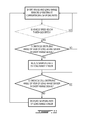
- Figs 11 and 12 show simplified flow charts showing a method of operating the system.
- Fig. 11 what is shown is an exemplary method for determining an appropriate condition for reducing the sampling rate of the long range sensor.
- a condition likely indicating that the long-range sensor input is not of use that is when one or more obstacles in the short range field of view are completely obstructing the long range field of view.
- at least a first condition for reducing the long range sensor sampling speed can be determined to be fulfilled. This scenario will typically occur at relatively low speeds, such as when the vehicle is stopped at a light or when the vehicle is driving slowly in dense traffic conditions, at which times it is safe to reduce the vigilance of the long-range sensor.
- a vehicle speed condition can also be used to trigger increasing the sampling rate of the long range sensor back to a higher value.
- Fig. 12 what is shown is an exemplary method for reducing the sampling rate of the short range sensor.
- This can be the case for example when both the short range sensor and the long range sensor inputs do not indicate the presence of an obstacle. This is likely to happen at highway conditions for instance and so an optional minimal vehicle speed can also optionally be set as a condition (not shown in the flow chart for simplicity).
- the sampling rate of the short range sensor is reduced in this example.
- the threshold value of incoming relative speed can be established taking into account the distance of the obstacle and/or the speed of the vehicle for instance.
Landscapes
- Engineering & Computer Science (AREA)
- Physics & Mathematics (AREA)
- Electromagnetism (AREA)
- Remote Sensing (AREA)
- General Physics & Mathematics (AREA)
- Radar, Positioning & Navigation (AREA)
- Computer Networks & Wireless Communication (AREA)
- Mechanical Engineering (AREA)
- Automation & Control Theory (AREA)
- Mathematical Physics (AREA)
- Transportation (AREA)
- Multimedia (AREA)
- Optical Radar Systems And Details Thereof (AREA)
- Traffic Control Systems (AREA)
Abstract
Description
- The improvements generally relate to the field of vehicular perception systems for automotive vehicles, and more specifically relates to a vehicular object ranging system having both a short range sensor and a long range sensor.
- Vehicular perception systems have been in development for several years, notably in automotive applications. It is known to use active sensors in such systems, which include both an emitter and a detector. An example of active sensors is LIDAR (LIght Detection And Ranging) technology, where a light signal can be emitted by a LED (Light Emitting Diode) or laser emitter (such as laser diode), for instance, and is later received by an associated detector. Although former systems were satisfactory to a certain degree, there remained room for improvement.
- In accordance with one aspect, it was found that for many applications, a wider field of view was required at short range than at longer range. Henceforth, instead of using a single active sensor with a wide field of view requirement to cover an entire range requirement, a combination of active sensors can be used. A shorter range sensor can be diffused over a wider field of view which can be required at shorter range, whereas a long range sensor can have its power concentrated over a narrower field of view to significantly reduce its power requirement compared to a sensor having the same range but a field of view meeting the shorter range field of view requirement.
- Further, one significant concern of such systems was the durability of the components, or the mean-time between failures (MTBF). This was particularly the case for instance where the sensors used laser based emission, for instance, or other types of emitters having high costs.
- It was found that the mean-time between failures could be improved in vehicular object ranging systems having a long-range lidar sensor having and a short-range lidar sensor by reducing the sampling rate of at least one of the sensors based on information provided by the sensors themselves, when certain conditions were met.
- Henceforth, this application describes a method of modulation of the sampling frequencies of two complementary obstacle detection and ranging subsystems in order to reduce the number of emitted laser pulses required for the operation of said subsystems, thus increasing the lifespan of the laser emitters of the subsystems. Each of the subsystems having complementary obstacle range capability in order to meet the requirements of different obstacle detection situations. A short-range and wide field-of-view object detection and ranging subsystem system is typically required for collision mitigation systems in low-speed driving situations (typically, urban "stop-and-go" collision mitigation applications. A long-range and narrow field-of-view object detection and ranging subsystem system is also typically required for collision mitigation systems in high-speed driving situations (typically, highway or high-speed collision mitigation applications). The use of each of the subsystems can be considered exclusive in some driving situations. In those cases, using a feedback loop between the two obstacle detection and ranging subsystems, the sampling frequency of one of the subsystems can be reduced substantially (and in some cases, reduced to 0), while the frequency of the complementary subsystem is maintained at a normal operating frequency. In embodiments using laser emission for instance, the reduction of the sampling rate of the subsystems is expected to provide a reduction of the total pulses emitted by the laser sources of each subsystem. The number of laser pulses being one important factor in determining the MTBF of pulsed laser sources, the invention will increase the MTBF of each of the subsystems. The actual improvement on the MTBF of the laser-based subsystems will be dependent on other factors, such as the MTBF of all physical components of each subsystems as well as variations in the driving conditions in which the subsystems are used. Nonetheless, important improvement of the laser-based obstacle detection and ranging subsystems MTBF are expected.
- In accordance with one aspect, there is provided a method of operating a vehicular object ranging system having a long-range laser LIDAR system having a long-range field of view and a long-range depth, and a short-range laser LIDAR system having a short-range field of view overlapping and exceeding said long-range field of view and a short-range depth smaller than said long-range depth, said method comprising operating one of said long-range sensor and said short-range sensor while simultaneously maintaining the other one of said long-range sensor and said short-range sensor in one of a reduced activation mode and an inactive mode.
- In accordance with another aspect, there is provided a method of operating a vehicular object ranging system having a long-range sensor having a long-range field of view and a short-range sensor having a short-range field of view overlapping and exceeding said long-range field of view and having an angular resolution capability, said method comprising: operating the long-range sensor at a long-range sampling rate to generate at least one indication of one of an absence and a range of an object within said long-range field of view; operating the short-range sensor at a short-range sampling rate to generate at least one indication of one of an absence and a range of an object within said short-range field of view; and varying the sampling rate of one of the long-range sensor and the short-range sensor based on the at least one indication provided by the other one of the long-range sensor and the short-range sensor.
- In accordance with another aspect, there is provided a vehicular object ranging system having a housing containing a long-range sensor having a long-range field of view and a long-range depth and a short-range sensor having a short-range field of view overlapping and exceeding said long-range field of view and a short-range depth smaller than said long-range depth, and a control module having a function to operate one of said long-range sensor and said short-range sensor while simultaneously maintaining the other one of said long-range sensor and said short-range sensor in one of a reduced activation mode and an inactive mode..
- Many further features and combinations thereof concerning the present improvements will appear to those skilled in the art following a reading of the instant disclosure. For instance, in the case of each one of the long range and short range subsystems, the depth signal can be combined to a color signal from a camera into a fused RGBD (Red, Green, Blue, Depth) or RGBID (Red, Green, Blue, Depth, Intensity) signal to become a power acquisition apparatus.
- In the figures,
-
Figs. 1 to 3 are schematic views of a first example of a vehicular object ranging system; -
Figs. 4 to 7 show different scenarios; -
Fig. 8 is a block diagram of a proposed embodiment of a vehicular object ranging system; -
Fig. 9 is a block diagram of an alternate embodiment; -
Fig. 10 is a block diagram of an example of a complete system; -
Fig. 11 is a flow chart showing variation of the sampling rate of the long-range sensor based on the output of the short-range sensor; and -
Fig. 12 is a flow chart showing variation of the sampling rate of the short-range sensor based on the output of the long-range sensor. -
Fig.1 shows an example of field of view and depth of view for an object ranging system of avehicle 10, the object ranging system having two sensors subsystems, including a first sensor subsystem referred to as a short range sensor which has a short field ofview 11 covering a horizontal angle α and adepth 12, and a second sensor subsystem referred to as a long range sensor having a long field ofview 15 covering a narrower horizontal angle β but agreater depth 16. The two subsystems can be used independently for different road safety applications in this example. For instance, the short-range field ofview 11 can satisfy the requirements of some low-speed collision avoidance applications, such as high-density traffic braking assistance systems for instance (examples of which are described later in the text), and can be adapted for the detection of some collision situations where the relative speed of the obstacle is relatively low, as in "cut-in" detection applications or lane change assistance applications (a cut-in scenario is shown inFig. 1 ). On the other hand, the long range field ofview 15 can be used for high-speed driving situations (such as on highways), to give sufficient reaction time to collision avoidance systems in high speed situations. The narrower field of view is selected to optimize usage of the system resources (such as emitter power or the angular resolution of detectors) to the region where obstacles are most likely to be detected in such driving situations. - It will be seen from the description below, that in this example, the output from one of the sensors can be used in determining an appropriate condition to reduce the sampling rate of the other sensor.
- In one embodiment, both the short range sensor and the long range sensor are laser LIDAR subsystems having angular resolution capability. The short-range sensor field of view is more clearly shown in
Fig. 2 as having emission and associated detection spanning a 60° field of view (i.e. 30° to each side in front of the vehicle), reaching a range of approximately 55 meters from the front of the vehicle, whereas the long-range sensor can be concentrated on an 11° field of view and can be used to sense 3 lanes wide in the range of between 50 and 150 meters. Alternative embodiments can have the short range sensor having a field of view between 40 and 80°, preferably between 50 and 70, and a range of 100 meters, preferably up to 70 meters, for instance and have the long range sensor having a field of view between 5 and 20°, preferably between 10 and 15, and a range of up to 200 meters, or up to 170 meters, for instance, for automotive applications. The short range lidar subsystem can have a 16x 1, 32X1 or similar horizontally oriented array of detectors each covering a given angular span in the field of view for example. In the embodiment shown inFig. 2 , the individual angular span is of 1.8° for a 32X1 array. The long-range sensor can be linear mode FPA with configurations like 32 x 16 pixels concentrated on the narrower field of view. The angular resolution is optional especially for the long-range sensor. Having 32X 16 type of FPA can be useful in the long range applications to determine the depth ( volume ) that can be translated detecting and understanding multiple vehicles if they are close proximity to each other. The angular resolution is optional and can be omitted in alternate embodiment, especially for the long range sensor. InFig. 3 , a long-range subsystem having a 8X1 array is shown with each individual sensor coverin a 1.3° field of view. - The two sensors can provide indications of different scenarios. For instance, in
Figs 2 and 3 , both sensors can provide an indication of absence of objects in the respective fields of view, which indication can be used to trigger a reduction in the sampling rate of the short range sensor, for instance. InFig. 4 , the short-range sensor can provide an indication that an object in the short range field of view, completely blocs the long-range field of view. This condition can trigger a reduction of the sampling rate of the long-range field of view, potentially down to zero, to thereby improve its mean-time between failure, for instance. - Many types of vehicular ranging systems include sensors which operate at given sampling rates, such as laser emission sensors, LED based lidars, or radars. Lasers and LED's are particularly susceptible to premature failure when compared to radars. The sampling rates can be regular or irregular. In the case of regular sampling rates, the expression "frequency" is used.
-
Fig. 8 shows a functional block diagram of a proposed embodiment. This embodiment comprises a short-range (wide field of view) obstacle detection and ranging subsystem, a long-range (narrow field of view) obstacle detection and ranging subsystem and a control module. - In this embodiment, the short-range obstacle detection and ranging subsystem is composed of a laser emitter and accompanying optics and an optical detector with accompanying optics. The subsystem also contains a pulse generator used to periodically trigger the laser emitter in the generation of a pulse sequence, the periodicity of the pulse (or inversely, the related sampling frequency) of the pulse sequence being a controllable parameter. An obstacle and range detection module is used to interpret the optical detector input and translate it into actual identification of obstacles and range, providing identifiable characteristics of the obstacles (such as dimension) as a function of the capability of the detector, discussed further in the document. Additional support components, such as temperature monitoring and conditioning are also included in the subsystem. Finally, the subsystem contains a parameter and control module, used to obtain operation and control commands from the main control module and to ensure their proper application to the component modules of the subsystem.
- In this embodiment, the detectors of the short-range obstacle detection and ranging subsystem is an arrayed detector, providing the capability to the subsystem of a fine angular resolution for obstacle detection within the field of view of the system. For example, using a linear array detector and a FOV of 60 degrees, the average coverage by detector "pixel" would be on average below 2 degrees.
- In this embodiment, the long-range obstacle detection and ranging subsystem is configured in a similar fashion to the short-range, wide field of view obstacle detection and ranging subsystem. The differences between the two subsystems reside in the adaptations of the emitter and detector optics to the varying field of view, and in the use of different emitter wavelengths for each subsystem, with the subsequent adaptations of the emitter and detector optics and filters to the wavelength used by the subsystem. The long-range obstacle detection and ranging subsystem is able to provide the distance of the objects detected The long-range obstacle detection and ranging subsystems can also optionally provide angular position and angular dimensions similar to those provided by the short-range subsystem.
- The control module acquires, through communication with the parameter and control module of both subsystems, the obstacle identification of obstacles and range from both subsystems. Using rules (discussed further in the document), to assess the driving situation and determine the required usage of each of the subsystems, the Control Module instructs each of the subsystems on the recommended sampling frequency to be used.
- In some embodiments, the pulse sequence generated by the pulse generator can be a single pulse. In other embodiments, the pulse sequence can be comprised of multiple pulses, evenly or unevenly spaced.
- In this embodiment, the output beam can be diffused by a proper lens, in a way to cover an area of interest with a single pulse as opposed to scanning lasers for instance.
- In some embodiments, the emitter and detector subsystems need not be based on laser emitters or optical receivers. The subsystems can be based on alternate obstacle detection and ranging technologies, such as radar or acoustic techniques. The nature of the subsystem does not impact on the potential for improvement on the MTBF using the sampling frequency modulation described as part of this invention.
- Using the described architecture, the Control Module can implement hardware control of the sampling frequency of both subsystems in order to improve on the MTBF of the subsystem components as described below.
- In the case where an object or multiple objects are detected by the short-range subsystem, within its detection range, and where said objects are known to have an combined angular dimension which covers totally the field of view of the long-range subsystem, the long-range subsystem sampling rate can be significantly reduced (and even shut down or placed in an other energy saving mode, if the embodiment permits). The sampling rate of the short-range subsystem can be kept at its maximal rate.
- In this case, a total obstruction of the field of view of the long-range subsystem is assumed when either of the following conditions are met:
- - A single obstacle detected by the short-range detection subsystem is determined to obscure completely the long range detection subsystem's field of view (as per
Fig. 4 ) - - Multiple obstacles detected by the short-range detection subsystem are determined to obscure completely the long range detection subsystem's field of view (as per
Fig. 5 ). - For concerning the latter, the calculated width of each identified object can be cumulated with a margin of error equivalent to the angular resolution of the long-range detection subsystem on each side of the object. For example, multiple obstacles detected by the short-range detection subsystem can be determined to obscure completely the long-range detection subsystem's field of view (as per
Fig. 6 ) when the gap between obstacles is less than twice the angular resolution of the long-range detection subsystem. Also objects can be determined to exceed the long-range detection subsystem's field of view limits when they are within once the angular resolution of the long-range detection subsystem. - In the condition where multiple obstacles are detected by the short-range detection subsystem but where the gap between the objects exceeds or is equal to twice the angular resolution of the long-range detection subsystem (as per
Fig. 7 , for instance), it can be considered that the long-range detection subsystem should still operate, perhaps at a normal operation sampling rate. - In the case where an object is detected by the long-range subsystem, within its detection range but outside of the short-range subsystem, and where the short-range subsystem has no object within its detection range, and where the vehicle speed exceeds a minimum threshold (for example 60km/h), the sampling rate of the short range subsystem can be reduced to a factor determined by the safety margins established for the embodiment.
- In other cases, both subsystems should be operated at maximum sampling frequency.
- The safety margin established by the embodiment can be proportional to vehicle speed, and detection range of the short-range subsystem with a set minimum threshold.
- This last strategy is explained by the fact that, in high-speed driving situations, the short-range subsystem is usually used in support of the detection of vehicle "cut-in" situations, for collision avoidance and lane change assistance applications. In those cases, the relative speed of the obstacles is relatively low compared to the ego-motion of the vehicle.
- A potential threat is the possibility of a head-on collision with an oncoming obstacle that is coming from outside the FOV of the long-range subsystem. In those cases, the reduction in sampling rate can be determined to have only a marginal effect on the reaction time. For instance, using a 55 meter depth of view for the short-range detection system, and an impending head-on collision of 2 vehicles, each with an ego speed at 100 km/h. In this case, relative speed between vehicles is 55m/s. With a 100 Hz sampling rate, the distance a vehicle travels between samples is 0,5m, while, with a 10 Hz sampling rate, the distance a vehicle travels is 5,5 m. This amounts to less than 1/10 of a second difference between both sampling rates.
- Other embodiments may utilise other strategies.
-
Fig. 9 describes another proposed embodiment of the invention where only the emitter portions of the short-range and long-range subsystems are distinct. In this embodiment, the receiver portion is common to both subsystems. This is accomplished by using emitters that use the same wavelength. The receiver optics is comprised of separate lenses to accommodate the different field of views, and the collimated beams at the receiver end are transmitted to a single optical receiver using optical devices to insert both beams in a single optical path. The pulse generator and conditioner module can alternately trigger each of the emitters sequentially, rather than simultaneously. -
Fig. 10 describes a proposed embodiment with complementary details pertaining to the implementation within a complete automotive collision avoidance detector system. In this embodiment, independent short arrange and long range subsystems are implemented, using 3D Flash LIDAR technology. The functions performed by the Obstacle detection and Range detection Module of both subsystems are now performed in the Video Processor located in the Control Modules. The embodiment also incorporates a video acquisition subsystem and presents the interfaces of the sensor system to automotive platform components. -
Figs 11 and12 show simplified flow charts showing a method of operating the system. InFig. 11 , what is shown is an exemplary method for determining an appropriate condition for reducing the sampling rate of the long range sensor. Essentially, what is to be determined in this example is a condition likely indicating that the long-range sensor input is not of use, that is when one or more obstacles in the short range field of view are completely obstructing the long range field of view. When this is the case, at least a first condition for reducing the long range sensor sampling speed can be determined to be fulfilled. This scenario will typically occur at relatively low speeds, such as when the vehicle is stopped at a light or when the vehicle is driving slowly in dense traffic conditions, at which times it is safe to reduce the vigilance of the long-range sensor. Henceforth, in dotted lines, an additional condition is shown for this example : that the vehicle speed is below a given threshold value, which can be set to 15, 30, or 50 mph for instance, for the sampling rate of the long range sensor to be reduceable. Although not shown in the flow chart for the sake of simplicity, it will be understood that a vehicle speed condition can also be used to trigger increasing the sampling rate of the long range sensor back to a higher value. - In
Fig. 12 , what is shown is an exemplary method for reducing the sampling rate of the short range sensor. This can be the case for example when both the short range sensor and the long range sensor inputs do not indicate the presence of an obstacle. This is likely to happen at highway conditions for instance and so an optional minimal vehicle speed can also optionally be set as a condition (not shown in the flow chart for simplicity). Henceforth, in the case where both short range field of view and long range field of view are free from obstacles, the sampling rate of the short range sensor is reduced in this example. Also, as shown, even in the case where an obstacle is present in the long range field of view, but where this obstacle is determined from successive samplings of the long range sensor to have a relative speed with the vehicle which is either outgoing (i.e. moving away from the vehicle), or incoming at a relative speed below a threshold value. The threshold value of incoming relative speed can be established taking into account the distance of the obstacle and/or the speed of the vehicle for instance. - Further, although not necessarily shown in the flow charts for the sake of simplicity, it will be understood that there can be exceptions which prevent the reducing of the sampling rate although certain conditions are detected. This can be the case for example in adverse weather conditions for instance, where both long range sensor and short range sensor can be kept in a state of maximal alert for instance. Determining a state of adverse weather condition (such as direct sunlight, fog, rain, snow, etc.) can be done using an input from the sensors themselves, or from another subsystem for instance, such as a camera (e.g. CMOS) to name an example. Henceforth, the camera input, in embodiments where a camera is used, its signal can be used in determining whether or not reducing sampling rates is appropriate.
- As can be understood from the discussion above and the various embodiments presented, the examples described above and illustrated are intended to be exemplary only. The scope is indicated by the appended claims.
Claims (16)
- A method of operating a vehicular object ranging system having a long-range sensor having a long-range field of view and a long-range depth, and a short-range sensor having a short-range field of view overlapping and exceeding said long-range field of view and a short-range depth smaller than said long-range depth, said method comprising operating one of said long-range sensor and said short-range sensor while simultaneously maintaining the other one of said long-range sensor and said short-range sensor in one of a reduced activation mode and an inactive mode.
- The method of claim 1 comprising:operating the long-range sensor at a long-range sampling rate to generate at least one indication of one of an absence and a range of an object within said long-range field of view;operating the short-range sensor at a short-range sampling rate to generate at least one indication of one of an absence and a range of an object within said short-range field of view; andvarying the sampling rate of one of the long-range sensor and the short-range sensor based on the at least one indication provided by the other one of the long-range sensor and the short-range sensor.
- The method of claim 1 or 2 wherein the long-range sensor is a long-range LIDAR system having a long-range depth, and the short-range sensor is a short-range LIDAR system having a short-range depth smaller than said long-range depth.
- The method of claim 2 wherein the step of varying includes reducing the sampling rate.
- The method of claim 2 or 4 wherein the step of varying is further based on determining that a speed of the vehicle is one of above and below a given value.
- The method of claim 2, 4 or 5 wherein the step of varying is further based on determining a favourable state of weather conditions.
- The method of claim 2, 4, 5 or 6 wherein the step of varying includes reducing the sampling rate of the long range sensor based on the short range sensor generating at least one indication a range of an object within said short-range field of view, said indication further including an indication that the object totally covers the long-range field of view.
- The method of claim 2, 4, 5, 6 or 7 wherein the step of varying is further based on determining that a speed of the vehicle is below a threshold value.
- The method of claim 2, 4, 5, 6, 7 or 8 wherein said reducing includes stopping the sampling of the long-range subsystem while maintaining the sampling rate of the short range subsystem at a maximal value.
- The method of claim 2, 4, 5, 6, 7, 8 or 9 wherein the step of varying includes reducing the sampling rate of the short range sensor based on an indication of absence of an object from both the short range sensor and the long range sensor.
- The method of claim 2, 4, 5, 6, 7, 8, 9 or 10 wherein the step of varying includes reducing of the sampling rate of the short-range sensor based on the long-range sensor generating an indication of a range of an object and the short-range sensor generating an indication of an absence of an object in the short range field of view.
- The method of claim 2, 4, 5, 6, 7, 8, 9, 10 or 11 wherein said reducing is further based on an indication that a vehicle speed exceeds a minimum value.
- The method of claim 2, 4, 5, 6, 7, 8, 9, 10, 11 or 12 further comprising evaluating the relative speed of an object in the long range field of view based on at least two indications of range of an object of the long-range sensor; comparing the relative speed of an object to an incoming speed threshold value; and wherein the step of varying includes reducing the sampling rate of the short range sensor based on determining that the relative speed of an object is below the incoming speed threshold value.
- A vehicular object ranging system having a housing containing a long-range sensor having a long-range field of view and a long-range depth and a short-range sensor having a short-range field of view overlapping and exceeding said long-range field of view and a short-range depth smaller than said long-range depth, and a control module having a function to operate one of said long-range sensor and said short-range sensor while simultaneously maintaining the other one of said long-range sensor and said short-range sensor in one of a reduced activation mode and an inactive mode.
- The vehicular object ranging system of claim 14 wherein
the short range sensor is a short-range laser LIDAR subsystem operable within a range of short-range sampling rates, including at least one emitter and a receiver, a mechanism to determine sampling rate of said subsystem, and the capability to provide the angular position and horizontal angular dimension within the field of view of objects detected and the range of the objects detected,
the long range sensor is a long-range laser LIDAR subsystem operable within a range of long-range sampling rates, including at least one emitter and a receiver, a mechanism to determine a sampling rate of said subsystem, and the capability to provide the range of objects detected within the long-range field of view, and
the control module is capable of acquiring an indication of absence and range of objects from the short range laser LIDAR subsystem and the long range laser LIDAR subsystem, and capable, based on this acquired information, to vary the sampling rate of the abovementioned subsystems. - A vehicle comprising the vehicular object ranging system of claims 14 or 15.
Applications Claiming Priority (1)
| Application Number | Priority Date | Filing Date | Title |
|---|---|---|---|
| US201161467445P | 2011-03-25 | 2011-03-25 |
Publications (2)
| Publication Number | Publication Date |
|---|---|
| EP2503357A1 true EP2503357A1 (en) | 2012-09-26 |
| EP2503357B1 EP2503357B1 (en) | 2014-12-31 |
Family
ID=45032517
Family Applications (1)
| Application Number | Title | Priority Date | Filing Date |
|---|---|---|---|
| EP12160948.1A Not-in-force EP2503357B1 (en) | 2011-03-25 | 2012-03-23 | Vehicular ranging system and method of operation |
Country Status (5)
| Country | Link |
|---|---|
| US (1) | US9897700B2 (en) |
| EP (1) | EP2503357B1 (en) |
| JP (1) | JP5238868B2 (en) |
| KR (1) | KR101071362B1 (en) |
| CA (1) | CA2772402A1 (en) |
Cited By (7)
| Publication number | Priority date | Publication date | Assignee | Title |
|---|---|---|---|---|
| DE102012018099A1 (en) * | 2012-09-13 | 2014-03-13 | Volkswagen Ag | Method for operating sensors e.g. stereo camera of sensor device used in e.g. passenger car, involves varying operating mode of sensor affecting power consumption of sensor based on determined environmental condition of motor vehicle |
| WO2017070127A1 (en) | 2015-10-21 | 2017-04-27 | Google Inc. | Methods and systems for clearing sensor occlusions |
| WO2018005784A1 (en) * | 2016-06-29 | 2018-01-04 | Apple Inc. | Optical systems for remote sensing receivers |
| EP3330741A1 (en) * | 2016-12-05 | 2018-06-06 | Sick Ag | Optoelectronic sensor and method for detecting objects in a surveillance area |
| WO2018160439A1 (en) * | 2017-03-01 | 2018-09-07 | Microsoft Technology Licensing, Llc | Multi-spectrum illumination-and-sensor module for head tracking, gesture recognition and spatial mapping |
| WO2019020244A1 (en) * | 2017-07-25 | 2019-01-31 | Robert Bosch Gmbh | Method for processing continuous sensor signals and sensor system |
| US10557943B2 (en) | 2016-08-22 | 2020-02-11 | Apple Inc. | Optical systems |
Families Citing this family (29)
| Publication number | Priority date | Publication date | Assignee | Title |
|---|---|---|---|---|
| KR20140079090A (en) | 2012-12-18 | 2014-06-26 | 한국전자통신연구원 | Laser emitter module and laser detecting system applied the same |
| US9062979B1 (en) | 2013-07-08 | 2015-06-23 | Google Inc. | Pose estimation using long range features |
| DE102013215117A1 (en) * | 2013-08-01 | 2015-02-05 | Robert Bosch Gmbh | Object determination by means of radar sensor |
| KR101551667B1 (en) * | 2013-11-27 | 2015-09-09 | 현대모비스(주) | LIDAR Sensor System |
| JP6316265B2 (en) * | 2015-12-01 | 2018-04-25 | 本田技研工業株式会社 | Lane change control device |
| WO2017218658A1 (en) * | 2016-06-14 | 2017-12-21 | Gentex Corporation | Imaging systems having an electrowetting lens |
| US20180067195A1 (en) * | 2016-09-08 | 2018-03-08 | Qualcomm Incorporated | Multi-tier light-based ranging systems and methods |
| KR102554215B1 (en) * | 2016-09-20 | 2023-07-11 | 이노비즈 테크놀로지스 엘티디 | Lidar systems and methods |
| WO2018056199A1 (en) * | 2016-09-21 | 2018-03-29 | 日本電気株式会社 | Distance measurement system, distance measurement method, and program recording device |
| US20180120439A1 (en) * | 2016-11-03 | 2018-05-03 | Honeywell International Inc. | Systems and methods for using dissimilar lidar technologies |
| US10469758B2 (en) | 2016-12-06 | 2019-11-05 | Microsoft Technology Licensing, Llc | Structured light 3D sensors with variable focal length lenses and illuminators |
| US10554881B2 (en) | 2016-12-06 | 2020-02-04 | Microsoft Technology Licensing, Llc | Passive and active stereo vision 3D sensors with variable focal length lenses |
| KR20190016254A (en) * | 2017-08-08 | 2019-02-18 | 삼성전자주식회사 | Method and apparatus for measurment of distance |
| WO2019033000A1 (en) * | 2017-08-10 | 2019-02-14 | Gentex Corporation | Low cost camera |
| JP7388720B2 (en) * | 2017-11-15 | 2023-11-29 | オプシス テック リミテッド | Noise-adaptive solid-state LIDAR system |
| KR20190055344A (en) | 2017-11-15 | 2019-05-23 | 김영현 | Object recognition headset |
| DE102017222969A1 (en) | 2017-12-15 | 2019-06-19 | Ibeo Automotive Systems GmbH | Method for improved near and far detection of a LIDAR receiving unit |
| US20190204845A1 (en) * | 2017-12-29 | 2019-07-04 | Waymo Llc | Sensor integration for large autonomous vehicles |
| ES2905110T3 (en) * | 2018-01-09 | 2022-04-07 | Signify Holding Bv | dual mode electronic device |
| JP7141242B2 (en) * | 2018-05-18 | 2022-09-22 | 株式会社小糸製作所 | sensor system |
| CN109857002B (en) * | 2019-01-15 | 2021-07-20 | 北京百度网讯科技有限公司 | Data acquisition method, device, equipment and computer readable storage medium |
| US11821977B2 (en) * | 2019-07-10 | 2023-11-21 | Samsung Electronics Co., Ltd. | Target detection and tracking for feature extraction |
| US11531107B2 (en) * | 2019-11-19 | 2022-12-20 | Volvo Car Corporation | Long range LIDAR-based speed estimation |
| CN113126060A (en) * | 2020-01-16 | 2021-07-16 | 浙江舜宇智能光学技术有限公司 | TOF camera module and drive control method thereof |
| DE102020208099A1 (en) | 2020-06-30 | 2021-12-30 | Robert Bosch Gesellschaft mit beschränkter Haftung | Method for determining a point cloud representing an environment of a LiDAR sensor |
| JP7423485B2 (en) * | 2020-09-18 | 2024-01-29 | 株式会社東芝 | distance measuring device |
| KR102517750B1 (en) * | 2020-12-28 | 2023-04-06 | 주식회사 비트센싱 | Radar apparatus and method for detecting object based on occurrence of event |
| US20220350000A1 (en) * | 2021-05-03 | 2022-11-03 | Velodyne Lidar Usa, Inc. | Lidar systems for near-field and far-field detection, and related methods and apparatus |
| WO2023059766A1 (en) * | 2021-10-06 | 2023-04-13 | Neural Propulsion Systems, Inc. | Hybrid lidar system |
Citations (1)
| Publication number | Priority date | Publication date | Assignee | Title |
|---|---|---|---|---|
| US20090254260A1 (en) * | 2008-04-07 | 2009-10-08 | Axel Nix | Full speed range adaptive cruise control system |
Family Cites Families (22)
| Publication number | Priority date | Publication date | Assignee | Title |
|---|---|---|---|---|
| JP3110562B2 (en) * | 1992-07-20 | 2000-11-20 | 富士通テン株式会社 | Inter-vehicle distance measuring device |
| JPH06174849A (en) * | 1992-12-04 | 1994-06-24 | Kansei Corp | Obstacle detecting device |
| JP3581911B2 (en) * | 1996-06-07 | 2004-10-27 | コニカミノルタホールディングス株式会社 | Mobile vehicle |
| US6580385B1 (en) * | 1999-05-26 | 2003-06-17 | Robert Bosch Gmbh | Object detection system |
| JP4717195B2 (en) * | 2000-10-12 | 2011-07-06 | 本田技研工業株式会社 | Object detection device for moving objects |
| GB2395261A (en) * | 2002-11-11 | 2004-05-19 | Qinetiq Ltd | Ranging apparatus |
| EP1652128B1 (en) * | 2003-07-07 | 2014-05-14 | Insurance Services Office, Inc. | Traffic information system |
| JP4335651B2 (en) * | 2003-12-03 | 2009-09-30 | 富士通テン株式会社 | Perimeter monitoring device |
| KR100559421B1 (en) | 2003-12-30 | 2006-03-10 | 현대자동차주식회사 | System for preventing rear-ending for vehicle |
| US7242343B1 (en) * | 2004-09-15 | 2007-07-10 | Rockwell Collins, Inc. | Directed sequential hazard assessment weather radar |
| JP3936713B2 (en) * | 2004-09-24 | 2007-06-27 | 三菱電機株式会社 | Rear side warning device for vehicles |
| FR2875913A1 (en) * | 2004-09-29 | 2006-03-31 | Sea On Line Sa | ANTI-COLLISION ALARM SYSTEM INSTALLED ON A MARINE VEHICLE AND ANTI-COLLISION ANALYSIS METHOD |
| TWI246594B (en) * | 2004-12-21 | 2006-01-01 | Asia Optical Co Inc | Velocity-detecting method and velocity-detecting device |
| JP2007101238A (en) * | 2005-09-30 | 2007-04-19 | Sharp Corp | Optical ranging sensor and electrical apparatus |
| SE528566C2 (en) * | 2005-12-13 | 2006-12-19 | Scania Cv Abp | Adaptive cruise control system for motor vehicle, simultaneously detects multiple vehicles in front and generates control sequence for each detected vehicle |
| US20070288734A1 (en) * | 2006-06-08 | 2007-12-13 | Luick David A | Double-Width Instruction Queue for Instruction Execution |
| US7518545B2 (en) * | 2006-10-26 | 2009-04-14 | Infineon Technologies Ag | Driver assistance system |
| US9117246B2 (en) * | 2007-07-17 | 2015-08-25 | Inthinc Technology Solutions, Inc. | System and method for providing a user interface for vehicle mentoring system users and insurers |
| US8918302B2 (en) * | 2008-09-19 | 2014-12-23 | Caterpillar Inc. | Machine sensor calibration system |
| US20110043814A1 (en) * | 2009-08-24 | 2011-02-24 | Raytheon Company | Ultra stable short pulse remote sensor |
| US8589066B2 (en) * | 2010-09-24 | 2013-11-19 | Telenav, Inc. | Navigation system with predicted positioning condition mechanism and method of operation thereof |
| KR101030763B1 (en) | 2010-10-01 | 2011-04-26 | 위재영 | Image acquisition unit, acquisition method and associated control unit |
-
2011
- 2011-04-20 KR KR1020110036729A patent/KR101071362B1/en active IP Right Grant
- 2011-11-08 JP JP2011244994A patent/JP5238868B2/en active Active
-
2012
- 2012-03-22 CA CA2772402A patent/CA2772402A1/en not_active Abandoned
- 2012-03-23 US US13/428,490 patent/US9897700B2/en active Active
- 2012-03-23 EP EP12160948.1A patent/EP2503357B1/en not_active Not-in-force
Patent Citations (1)
| Publication number | Priority date | Publication date | Assignee | Title |
|---|---|---|---|---|
| US20090254260A1 (en) * | 2008-04-07 | 2009-10-08 | Axel Nix | Full speed range adaptive cruise control system |
Cited By (21)
| Publication number | Priority date | Publication date | Assignee | Title |
|---|---|---|---|---|
| DE102012018099B4 (en) * | 2012-09-13 | 2021-05-20 | Volkswagen Ag | Method for operating a sensor device of a motor vehicle |
| DE102012018099A1 (en) * | 2012-09-13 | 2014-03-13 | Volkswagen Ag | Method for operating sensors e.g. stereo camera of sensor device used in e.g. passenger car, involves varying operating mode of sensor affecting power consumption of sensor based on determined environmental condition of motor vehicle |
| US11249182B2 (en) | 2015-10-21 | 2022-02-15 | Waymo Llc | Methods and systems for clearing sensor occlusions |
| WO2017070127A1 (en) | 2015-10-21 | 2017-04-27 | Google Inc. | Methods and systems for clearing sensor occlusions |
| KR20200083668A (en) * | 2015-10-21 | 2020-07-08 | 웨이모 엘엘씨 | Methods and systems for clearing sensor occlusions |
| CN112904343B (en) * | 2015-10-21 | 2024-05-17 | 伟摩有限责任公司 | Method and system for clearing sensor occlusion |
| CN112904343A (en) * | 2015-10-21 | 2021-06-04 | 伟摩有限责任公司 | Method and system for clearing sensor occlusion |
| EP3347784A4 (en) * | 2015-10-21 | 2019-04-17 | Waymo Llc | Methods and systems for clearing sensor occlusions |
| CN109196378B (en) * | 2016-06-29 | 2022-12-06 | 苹果公司 | Optical system for remote sensing receiver |
| CN109196378A (en) * | 2016-06-29 | 2019-01-11 | 苹果公司 | Optical system for remote sensing receiver |
| US10634770B2 (en) | 2016-06-29 | 2020-04-28 | Apple Inc. | Optical systems for remote sensing receivers |
| WO2018005784A1 (en) * | 2016-06-29 | 2018-01-04 | Apple Inc. | Optical systems for remote sensing receivers |
| US10557943B2 (en) | 2016-08-22 | 2020-02-11 | Apple Inc. | Optical systems |
| EP3330741A1 (en) * | 2016-12-05 | 2018-06-06 | Sick Ag | Optoelectronic sensor and method for detecting objects in a surveillance area |
| US10628950B2 (en) | 2017-03-01 | 2020-04-21 | Microsoft Technology Licensing, Llc | Multi-spectrum illumination-and-sensor module for head tracking, gesture recognition and spatial mapping |
| WO2018160439A1 (en) * | 2017-03-01 | 2018-09-07 | Microsoft Technology Licensing, Llc | Multi-spectrum illumination-and-sensor module for head tracking, gesture recognition and spatial mapping |
| TWI753189B (en) * | 2017-07-25 | 2022-01-21 | 德商羅伯特博斯奇股份有限公司 | Method for processing continuous sensor signals and sensor system |
| CN110945322A (en) * | 2017-07-25 | 2020-03-31 | 罗伯特·博世有限公司 | Method and sensor system for processing continuous sensor signals |
| CN110945322B (en) * | 2017-07-25 | 2022-05-17 | 罗伯特·博世有限公司 | Method and sensor system for processing continuous sensor signals |
| WO2019020244A1 (en) * | 2017-07-25 | 2019-01-31 | Robert Bosch Gmbh | Method for processing continuous sensor signals and sensor system |
| US11976943B2 (en) | 2017-07-25 | 2024-05-07 | Robert Bosch Gmbh | Method for processing continuous sensor signals, and sensor system |
Also Published As
| Publication number | Publication date |
|---|---|
| EP2503357B1 (en) | 2014-12-31 |
| JP2012202990A (en) | 2012-10-22 |
| US9897700B2 (en) | 2018-02-20 |
| CA2772402A1 (en) | 2012-09-25 |
| KR101071362B1 (en) | 2011-10-07 |
| US20120242972A1 (en) | 2012-09-27 |
| JP5238868B2 (en) | 2013-07-17 |
Similar Documents
| Publication | Publication Date | Title |
|---|---|---|
| EP2503357B1 (en) | Vehicular ranging system and method of operation | |
| US11609329B2 (en) | Camera-gated lidar system | |
| US20230305115A1 (en) | Lidar system communication using data encoding for communicating point cloud data | |
| US11802970B2 (en) | Alternating power-level scanning for time-of-flight lidar systems | |
| CN117561458A (en) | LIDAR system and method for vehicle corner mounting | |
| WO2023183599A1 (en) | Lidar system communication using data encoding for communicating point cloud data | |
| CN116148817B (en) | Dual-wavelength-based TOF laser radar system and anti-interference method thereof | |
| US20230305161A1 (en) | Real-time monitoring dc offset of adc data of lidar system | |
| WO2023220316A1 (en) | Dual emitting co-axial lidar system with zero blind zone | |
| US20230051395A1 (en) | Scout pulsing | |
| US11899108B2 (en) | Time-of-flight imaging system for autonomous movable objects | |
| US20230305124A1 (en) | Methods and systems of window blockage detection for lidar | |
| US20240103138A1 (en) | Stray light filter structures for lidar detector array | |
| US20230366984A1 (en) | Dual emitting co-axial lidar system with zero blind zone | |
| US11871130B2 (en) | Compact perception device | |
| US20240192331A1 (en) | Interference reduction | |
| US20240118401A1 (en) | Methods and systems for tracking zero-angle of a galvanometer mirror | |
| US20230324526A1 (en) | Method for accurate time-of-flight calculation on the cost-effective tof lidar system | |
| US20240134011A1 (en) | Two dimensional transmitter array-based lidar | |
| US20230266450A1 (en) | System and Method for Solid-State LiDAR with Adaptive Blooming Correction | |
| US20240134044A1 (en) | Laser source with multiple seeds for lidar | |
| US20230341532A1 (en) | Dynamic calibration method of avalanche photodiodes on lidar | |
| CN117178200A (en) | Dynamic pulse control for light detection and ranging light sources | |
| WO2023183425A1 (en) | Methods and systems of window blockage detection for lidar | |
| WO2024072664A1 (en) | Improvement on wavelength stability of multijunction diode laser in lidar |
Legal Events
| Date | Code | Title | Description |
|---|---|---|---|
| PUAI | Public reference made under article 153(3) epc to a published international application that has entered the european phase |
Free format text: ORIGINAL CODE: 0009012 |
|
| AK | Designated contracting states |
Kind code of ref document: A1 Designated state(s): AL AT BE BG CH CY CZ DE DK EE ES FI FR GB GR HR HU IE IS IT LI LT LU LV MC MK MT NL NO PL PT RO RS SE SI SK SM TR |
|
| AX | Request for extension of the european patent |
Extension state: BA ME |
|
| 17P | Request for examination filed |
Effective date: 20121219 |
|
| 17Q | First examination report despatched |
Effective date: 20131213 |
|
| GRAP | Despatch of communication of intention to grant a patent |
Free format text: ORIGINAL CODE: EPIDOSNIGR1 |
|
| RIC1 | Information provided on ipc code assigned before grant |
Ipc: G01S 17/93 20060101AFI20140617BHEP Ipc: G01S 7/486 20060101ALI20140617BHEP Ipc: G01S 17/87 20060101ALI20140617BHEP |
|
| INTG | Intention to grant announced |
Effective date: 20140714 |
|
| GRAS | Grant fee paid |
Free format text: ORIGINAL CODE: EPIDOSNIGR3 |
|
| GRAA | (expected) grant |
Free format text: ORIGINAL CODE: 0009210 |
|
| AK | Designated contracting states |
Kind code of ref document: B1 Designated state(s): AL AT BE BG CH CY CZ DE DK EE ES FI FR GB GR HR HU IE IS IT LI LT LU LV MC MK MT NL NO PL PT RO RS SE SI SK SM TR |
|
| REG | Reference to a national code |
Ref country code: CH Ref legal event code: EP Ref country code: GB Ref legal event code: FG4D |
|
| REG | Reference to a national code |
Ref country code: IE Ref legal event code: FG4D |
|
| REG | Reference to a national code |
Ref country code: AT Ref legal event code: REF Ref document number: 704729 Country of ref document: AT Kind code of ref document: T Effective date: 20150215 |
|
| REG | Reference to a national code |
Ref country code: DE Ref legal event code: R096 Ref document number: 602012004586 Country of ref document: DE Effective date: 20150219 |
|
| REG | Reference to a national code |
Ref country code: SE Ref legal event code: TRGR |
|
| PG25 | Lapsed in a contracting state [announced via postgrant information from national office to epo] |
Ref country code: LT Free format text: LAPSE BECAUSE OF FAILURE TO SUBMIT A TRANSLATION OF THE DESCRIPTION OR TO PAY THE FEE WITHIN THE PRESCRIBED TIME-LIMIT Effective date: 20141231 Ref country code: FI Free format text: LAPSE BECAUSE OF FAILURE TO SUBMIT A TRANSLATION OF THE DESCRIPTION OR TO PAY THE FEE WITHIN THE PRESCRIBED TIME-LIMIT Effective date: 20141231 Ref country code: NO Free format text: LAPSE BECAUSE OF FAILURE TO SUBMIT A TRANSLATION OF THE DESCRIPTION OR TO PAY THE FEE WITHIN THE PRESCRIBED TIME-LIMIT Effective date: 20150331 |
|
| REG | Reference to a national code |
Ref country code: NL Ref legal event code: VDEP Effective date: 20141231 |
|
| REG | Reference to a national code |
Ref country code: LT Ref legal event code: MG4D |
|
| PG25 | Lapsed in a contracting state [announced via postgrant information from national office to epo] |
Ref country code: RS Free format text: LAPSE BECAUSE OF FAILURE TO SUBMIT A TRANSLATION OF THE DESCRIPTION OR TO PAY THE FEE WITHIN THE PRESCRIBED TIME-LIMIT Effective date: 20141231 Ref country code: HR Free format text: LAPSE BECAUSE OF FAILURE TO SUBMIT A TRANSLATION OF THE DESCRIPTION OR TO PAY THE FEE WITHIN THE PRESCRIBED TIME-LIMIT Effective date: 20141231 Ref country code: GR Free format text: LAPSE BECAUSE OF FAILURE TO SUBMIT A TRANSLATION OF THE DESCRIPTION OR TO PAY THE FEE WITHIN THE PRESCRIBED TIME-LIMIT Effective date: 20150401 Ref country code: LV Free format text: LAPSE BECAUSE OF FAILURE TO SUBMIT A TRANSLATION OF THE DESCRIPTION OR TO PAY THE FEE WITHIN THE PRESCRIBED TIME-LIMIT Effective date: 20141231 |
|
| REG | Reference to a national code |
Ref country code: AT Ref legal event code: MK05 Ref document number: 704729 Country of ref document: AT Kind code of ref document: T Effective date: 20141231 |
|
| PG25 | Lapsed in a contracting state [announced via postgrant information from national office to epo] |
Ref country code: NL Free format text: LAPSE BECAUSE OF FAILURE TO SUBMIT A TRANSLATION OF THE DESCRIPTION OR TO PAY THE FEE WITHIN THE PRESCRIBED TIME-LIMIT Effective date: 20141231 |
|
| PG25 | Lapsed in a contracting state [announced via postgrant information from national office to epo] |
Ref country code: SK Free format text: LAPSE BECAUSE OF FAILURE TO SUBMIT A TRANSLATION OF THE DESCRIPTION OR TO PAY THE FEE WITHIN THE PRESCRIBED TIME-LIMIT Effective date: 20141231 Ref country code: CZ Free format text: LAPSE BECAUSE OF FAILURE TO SUBMIT A TRANSLATION OF THE DESCRIPTION OR TO PAY THE FEE WITHIN THE PRESCRIBED TIME-LIMIT Effective date: 20141231 Ref country code: ES Free format text: LAPSE BECAUSE OF FAILURE TO SUBMIT A TRANSLATION OF THE DESCRIPTION OR TO PAY THE FEE WITHIN THE PRESCRIBED TIME-LIMIT Effective date: 20141231 Ref country code: RO Free format text: LAPSE BECAUSE OF FAILURE TO SUBMIT A TRANSLATION OF THE DESCRIPTION OR TO PAY THE FEE WITHIN THE PRESCRIBED TIME-LIMIT Effective date: 20141231 |
|
| PG25 | Lapsed in a contracting state [announced via postgrant information from national office to epo] |
Ref country code: PL Free format text: LAPSE BECAUSE OF FAILURE TO SUBMIT A TRANSLATION OF THE DESCRIPTION OR TO PAY THE FEE WITHIN THE PRESCRIBED TIME-LIMIT Effective date: 20141231 Ref country code: IS Free format text: LAPSE BECAUSE OF FAILURE TO SUBMIT A TRANSLATION OF THE DESCRIPTION OR TO PAY THE FEE WITHIN THE PRESCRIBED TIME-LIMIT Effective date: 20150430 Ref country code: AT Free format text: LAPSE BECAUSE OF FAILURE TO SUBMIT A TRANSLATION OF THE DESCRIPTION OR TO PAY THE FEE WITHIN THE PRESCRIBED TIME-LIMIT Effective date: 20141231 |
|
| REG | Reference to a national code |
Ref country code: DE Ref legal event code: R097 Ref document number: 602012004586 Country of ref document: DE |
|
| PG25 | Lapsed in a contracting state [announced via postgrant information from national office to epo] |
Ref country code: LU Free format text: LAPSE BECAUSE OF FAILURE TO SUBMIT A TRANSLATION OF THE DESCRIPTION OR TO PAY THE FEE WITHIN THE PRESCRIBED TIME-LIMIT Effective date: 20150323 Ref country code: EE Free format text: LAPSE BECAUSE OF FAILURE TO SUBMIT A TRANSLATION OF THE DESCRIPTION OR TO PAY THE FEE WITHIN THE PRESCRIBED TIME-LIMIT Effective date: 20141231 Ref country code: MC Free format text: LAPSE BECAUSE OF FAILURE TO SUBMIT A TRANSLATION OF THE DESCRIPTION OR TO PAY THE FEE WITHIN THE PRESCRIBED TIME-LIMIT Effective date: 20141231 Ref country code: DK Free format text: LAPSE BECAUSE OF FAILURE TO SUBMIT A TRANSLATION OF THE DESCRIPTION OR TO PAY THE FEE WITHIN THE PRESCRIBED TIME-LIMIT Effective date: 20141231 |
|
| REG | Reference to a national code |
Ref country code: CH Ref legal event code: PL |
|
| PLBE | No opposition filed within time limit |
Free format text: ORIGINAL CODE: 0009261 |
|
| STAA | Information on the status of an ep patent application or granted ep patent |
Free format text: STATUS: NO OPPOSITION FILED WITHIN TIME LIMIT |
|
| 26N | No opposition filed |
Effective date: 20151001 |
|
| REG | Reference to a national code |
Ref country code: IE Ref legal event code: MM4A |
|
| PG25 | Lapsed in a contracting state [announced via postgrant information from national office to epo] |
Ref country code: IE Free format text: LAPSE BECAUSE OF NON-PAYMENT OF DUE FEES Effective date: 20150323 Ref country code: CH Free format text: LAPSE BECAUSE OF NON-PAYMENT OF DUE FEES Effective date: 20150331 Ref country code: LI Free format text: LAPSE BECAUSE OF NON-PAYMENT OF DUE FEES Effective date: 20150331 |
|
| PG25 | Lapsed in a contracting state [announced via postgrant information from national office to epo] |
Ref country code: SI Free format text: LAPSE BECAUSE OF FAILURE TO SUBMIT A TRANSLATION OF THE DESCRIPTION OR TO PAY THE FEE WITHIN THE PRESCRIBED TIME-LIMIT Effective date: 20141231 |
|
| REG | Reference to a national code |
Ref country code: FR Ref legal event code: PLFP Year of fee payment: 5 |
|
| PG25 | Lapsed in a contracting state [announced via postgrant information from national office to epo] |
Ref country code: BE Free format text: LAPSE BECAUSE OF FAILURE TO SUBMIT A TRANSLATION OF THE DESCRIPTION OR TO PAY THE FEE WITHIN THE PRESCRIBED TIME-LIMIT Effective date: 20141231 |
|
| GBPC | Gb: european patent ceased through non-payment of renewal fee |
Effective date: 20160323 |
|
| PG25 | Lapsed in a contracting state [announced via postgrant information from national office to epo] |
Ref country code: MT Free format text: LAPSE BECAUSE OF FAILURE TO SUBMIT A TRANSLATION OF THE DESCRIPTION OR TO PAY THE FEE WITHIN THE PRESCRIBED TIME-LIMIT Effective date: 20141231 |
|
| PG25 | Lapsed in a contracting state [announced via postgrant information from national office to epo] |
Ref country code: GB Free format text: LAPSE BECAUSE OF NON-PAYMENT OF DUE FEES Effective date: 20160323 |
|
| REG | Reference to a national code |
Ref country code: FR Ref legal event code: PLFP Year of fee payment: 6 |
|
| PG25 | Lapsed in a contracting state [announced via postgrant information from national office to epo] |
Ref country code: BG Free format text: LAPSE BECAUSE OF FAILURE TO SUBMIT A TRANSLATION OF THE DESCRIPTION OR TO PAY THE FEE WITHIN THE PRESCRIBED TIME-LIMIT Effective date: 20141231 Ref country code: SM Free format text: LAPSE BECAUSE OF FAILURE TO SUBMIT A TRANSLATION OF THE DESCRIPTION OR TO PAY THE FEE WITHIN THE PRESCRIBED TIME-LIMIT Effective date: 20141231 Ref country code: HU Free format text: LAPSE BECAUSE OF FAILURE TO SUBMIT A TRANSLATION OF THE DESCRIPTION OR TO PAY THE FEE WITHIN THE PRESCRIBED TIME-LIMIT; INVALID AB INITIO Effective date: 20120323 |
|
| PG25 | Lapsed in a contracting state [announced via postgrant information from national office to epo] |
Ref country code: CY Free format text: LAPSE BECAUSE OF FAILURE TO SUBMIT A TRANSLATION OF THE DESCRIPTION OR TO PAY THE FEE WITHIN THE PRESCRIBED TIME-LIMIT Effective date: 20141231 |
|
| PG25 | Lapsed in a contracting state [announced via postgrant information from national office to epo] |
Ref country code: PT Free format text: LAPSE BECAUSE OF FAILURE TO SUBMIT A TRANSLATION OF THE DESCRIPTION OR TO PAY THE FEE WITHIN THE PRESCRIBED TIME-LIMIT Effective date: 20150501 |
|
| PG25 | Lapsed in a contracting state [announced via postgrant information from national office to epo] |
Ref country code: TR Free format text: LAPSE BECAUSE OF FAILURE TO SUBMIT A TRANSLATION OF THE DESCRIPTION OR TO PAY THE FEE WITHIN THE PRESCRIBED TIME-LIMIT Effective date: 20141231 |
|
| REG | Reference to a national code |
Ref country code: FR Ref legal event code: PLFP Year of fee payment: 7 |
|
| PG25 | Lapsed in a contracting state [announced via postgrant information from national office to epo] |
Ref country code: MK Free format text: LAPSE BECAUSE OF FAILURE TO SUBMIT A TRANSLATION OF THE DESCRIPTION OR TO PAY THE FEE WITHIN THE PRESCRIBED TIME-LIMIT Effective date: 20141231 |
|
| PG25 | Lapsed in a contracting state [announced via postgrant information from national office to epo] |
Ref country code: AL Free format text: LAPSE BECAUSE OF FAILURE TO SUBMIT A TRANSLATION OF THE DESCRIPTION OR TO PAY THE FEE WITHIN THE PRESCRIBED TIME-LIMIT Effective date: 20141231 |
|
| PGFP | Annual fee paid to national office [announced via postgrant information from national office to epo] |
Ref country code: FR Payment date: 20190322 Year of fee payment: 8 Ref country code: IT Payment date: 20190325 Year of fee payment: 8 Ref country code: DE Payment date: 20190321 Year of fee payment: 8 |
|
| PGFP | Annual fee paid to national office [announced via postgrant information from national office to epo] |
Ref country code: SE Payment date: 20190320 Year of fee payment: 8 |
|
| REG | Reference to a national code |
Ref country code: DE Ref legal event code: R119 Ref document number: 602012004586 Country of ref document: DE |
|
| PG25 | Lapsed in a contracting state [announced via postgrant information from national office to epo] |
Ref country code: DE Free format text: LAPSE BECAUSE OF NON-PAYMENT OF DUE FEES Effective date: 20201001 Ref country code: FR Free format text: LAPSE BECAUSE OF NON-PAYMENT OF DUE FEES Effective date: 20200331 Ref country code: SE Free format text: LAPSE BECAUSE OF NON-PAYMENT OF DUE FEES Effective date: 20200324 |
|
| PG25 | Lapsed in a contracting state [announced via postgrant information from national office to epo] |
Ref country code: IT Free format text: LAPSE BECAUSE OF NON-PAYMENT OF DUE FEES Effective date: 20200323 |