EP2502732A1 - Method for producing composite material components, device for producing composite material components, and inspection device - Google Patents
Method for producing composite material components, device for producing composite material components, and inspection device Download PDFInfo
- Publication number
- EP2502732A1 EP2502732A1 EP10831574A EP10831574A EP2502732A1 EP 2502732 A1 EP2502732 A1 EP 2502732A1 EP 10831574 A EP10831574 A EP 10831574A EP 10831574 A EP10831574 A EP 10831574A EP 2502732 A1 EP2502732 A1 EP 2502732A1
- Authority
- EP
- European Patent Office
- Prior art keywords
- fiber
- reinforced plastic
- plastic tape
- lamination
- sites
- Prior art date
- Legal status (The legal status is an assumption and is not a legal conclusion. Google has not performed a legal analysis and makes no representation as to the accuracy of the status listed.)
- Withdrawn
Links
- 239000002131 composite material Substances 0.000 title claims abstract description 43
- 238000004519 manufacturing process Methods 0.000 title claims abstract description 16
- 238000007689 inspection Methods 0.000 title claims description 58
- 229920002430 Fibre-reinforced plastic Polymers 0.000 claims abstract description 149
- 239000011151 fibre-reinforced plastic Substances 0.000 claims abstract description 149
- 238000003475 lamination Methods 0.000 claims abstract description 145
- 238000000034 method Methods 0.000 claims abstract description 20
- 238000010030 laminating Methods 0.000 claims abstract description 5
- 230000010365 information processing Effects 0.000 claims description 11
- 238000009826 distribution Methods 0.000 description 9
- 238000003860 storage Methods 0.000 description 4
- 239000000470 constituent Substances 0.000 description 3
- 230000033001 locomotion Effects 0.000 description 2
- 230000007246 mechanism Effects 0.000 description 2
- 238000000465 moulding Methods 0.000 description 2
- 238000002360 preparation method Methods 0.000 description 2
- 238000010586 diagram Methods 0.000 description 1
- 238000003708 edge detection Methods 0.000 description 1
- 239000000835 fiber Substances 0.000 description 1
- 238000005259 measurement Methods 0.000 description 1
- 238000012986 modification Methods 0.000 description 1
- 230000004048 modification Effects 0.000 description 1
- 238000005096 rolling process Methods 0.000 description 1
Images





Classifications
-
- B—PERFORMING OPERATIONS; TRANSPORTING
- B29—WORKING OF PLASTICS; WORKING OF SUBSTANCES IN A PLASTIC STATE IN GENERAL
- B29C—SHAPING OR JOINING OF PLASTICS; SHAPING OF MATERIAL IN A PLASTIC STATE, NOT OTHERWISE PROVIDED FOR; AFTER-TREATMENT OF THE SHAPED PRODUCTS, e.g. REPAIRING
- B29C70/00—Shaping composites, i.e. plastics material comprising reinforcements, fillers or preformed parts, e.g. inserts
- B29C70/04—Shaping composites, i.e. plastics material comprising reinforcements, fillers or preformed parts, e.g. inserts comprising reinforcements only, e.g. self-reinforcing plastics
- B29C70/28—Shaping operations therefor
- B29C70/30—Shaping by lay-up, i.e. applying fibres, tape or broadsheet on a mould, former or core; Shaping by spray-up, i.e. spraying of fibres on a mould, former or core
- B29C70/38—Automated lay-up, e.g. using robots, laying filaments according to predetermined patterns
- B29C70/386—Automated tape laying [ATL]
Definitions
- the present invention relates to a method for producing composite material components in which a fiber-reinforced plastic member is used.
- the present application claims the right of priority to Japanese Patent Application No. 2009-263293 filed on November 18, 2009 , in Japan, with the content cited herewith.
- Patent Document 1 discloses an automatic lamination molding device which automatically carries out lamination and molding of a fiber-reinforced plastic tape by a fiber placement method. Patent Document 1 does not disclose determination of an attachment state of the fiber-reinforced plastic tape.
- Patent Document 2 discloses a pattern inspection method on the basis of edge detection.
- a method for producing composite material components, a device for producing composite material components, and an inspection device in the present invention prevent an incorrect determination "improper" being made of an attachment state of a properly attached fiber-reinforced plastic tape.
- the present invention adopts the following configurations corresponding to each drawing shown in an embodiment.
- reference numerals given to each constituent only exemplify the constituents and shall not be construed to limit the constituents.
- a method for producing a composite material component in the present invention has a process of laminating fiber-reinforced plastic tape.
- the method for producing the composite material component includes, determining an attachment state of the first fiber-reinforced plastic tape during lamination of the fiber-reinforced plastic tape at a plurality of sites (V1 to Vn) from an attachment starting site (V1) to an attachment ending site (Vn) of a first fiber-reinforced plastic tape (70).
- the lamination is stopped when it is determined that the first fiber-reinforced plastic tape overlaps with a second fiber-reinforced plastic tape at a first site (V3, V4) of the plurality of sites and that a gap exists between the first fiber-reinforced plastic tape and the second fiber-reinforced plastic tape at a second site (V1, V2, Vn) of the plurality of sites.
- the lamination is continued when it is determined that the first fiber-reinforced plastic tape overlaps with the second fiber-reinforced plastic tape at all of the plurality of sites.
- Determining of the attachment state may include taking a photograph of each image at the plurality of sites by a camera (32) mounted on a lamination head (23) which attaches the first fiber-reinforced plastic tape while moving, thereby taking photographs of a plurality of images and determining whether or not the first fiber-reinforced plastic tape overlaps with the second fiber-reinforced plastic tape or a gap exists between the first fiber-reinforced plastic tape and the second fiber-reinforced plastic tape on the basis of the number of rises in brightness detected from each image of the plurality of images at the plurality of sites.
- Determining the attachment state may include, calculating a gap amount between the first fiber-reinforced plastic tape and the second fiber-reinforced plastic tape on the basis of a distance between the rises in brightness when the number of rises in brightness is two.
- the lamination may be stopped when it is determined that a gap exists between the first fiber-reinforced plastic tape and the second fiber-reinforced plastic tape at all of the plurality of sites and that the gap amount between the first fiber-reinforced plastic tape and the second fiber-reinforced plastic tape is greater than a predetermined threshold value at least at one of the plurality of sites.
- the lamination may be carried out in accordance with a lamination program (27) which stipulates that the fiber-reinforced plastic tapes to be arranged on the same layer will not overlap with each other.
- a device for producing composite material components (10) of the present invention is provided with an automatic lamination device (20) which carries out lamination of fiber-reinforced plastic tape and an inspection device (30) which determines an attachment state of a first fiber-reinforced plastic tape at a plurality of sites (V1 to Vn) from an attachment starting site (V1) to an attachment ending site (Vn) of the first fiber-reinforced plastic tape (70) attached by the automatic lamination device during the lamination.
- the automatic lamination device stops the lamination when the inspection device determines that the first fiber-reinforced plastic tape overlaps with the second fiber-reinforced plastic tape at the first sites (V3, V4) of the plurality of sites and also determines that a gap exists between the first fiber-reinforced plastic tape and the second fiber-reinforced plastic tape at the second sites (V1, V2, Nn) of the plurality of sites.
- the automatic lamination device continues the lamination when the inspection device determines that the first fiber-reinforced plastic tape overlaps with the second fiber-reinforced plastic tape at all of the plurality of sites.
- the automatic lamination device may be provided with a lamination head (23) which attaches the first fiber-reinforced plastic tape, while moving.
- the inspection device may be provided with a camera (32) mounted on the lamination head. The camera takes a photograph of each image at the plurality of sites, thereby taking photographs of a plurality of images.
- the inspection device may determine whether or not the first fiber-reinforced plastic tape overlaps with the second fiber-reinforced plastic tape or a gap exists between the first fiber-reinforced plastic tape and the second fiber-reinforced plastic tape on the basis of the number of rises in brightness detected from each image of the plurality of images at the plurality of sites.
- the inspection device may calculate a gap amount between the first fiber-reinforced plastic tape and the second fiber-reinforced plastic tape on the basis of a distance between the rises in brightness.
- the automatic lamination device may stop the lamination when it is determined that a gap exists between the first fiber-reinforced plastic tape and the second fiber-reinforced plastic tape at all of the plurality of sites and that a gap amount between the first fiber-reinforced plastic tape and the second fiber-reinforced plastic tape is greater than a predetermined threshold value at least at one of the plurality of sites.
- the automatic lamination device may carry out the lamination in accordance with a lamination program (27) which stipulates that fiber-reinforced plastic tapes to be arranged on the same layer will not overlap with each other.
- the inspection device may be provided with a lighting (33).
- the camera may be mounted on the lamination head in such a manner as to be arranged directly above a side end of the first fiber-reinforced plastic tape and also face the side end.
- the lighting may be mounted on the lamination head in such a manner as to be arranged at a position deviated in a width direction of the first fiber-reinforced plastic tape from directly above the side end and also face the side end.
- An inspection device (30) of the present invention is provided with a camera (32) mounted on a lamination head (23) of an automatic lamination device (20) which carries out lamination of fiber-reinforced plastic tape and an information processing device (34).
- the lamination head attaches a first fiber-reinforced plastic tape (70) while moving during the lamination.
- the information processing device determines an attachment state of the first fiber-reinforced plastic tape at a plurality of sites (V1 to Vn) of the first fiber-reinforced plastic tape on the basis of a plurality of images photographed by the camera and outputs a lamination stopping signal or a lamination continuing signal on the basis of results determined regarding the attachment state.
- the information processing device may output the lamination stopping signal when it is determined that the first fiber-reinforced plastic tape overlaps with the second fiber-reinforced plastic tape at the first sites (V3, V4) of the plurality of sites and that a gap exists between the first fiber-reinforced plastic tape and the second fiber-reinforced plastic tape at the second sites (V1, V2, Vn) of the plurality of sites. Further, the information processing device may output the lamination continuing signal when it is determined that the first fiber-reinforced plastic tape overlaps with the second fiber-reinforced plastic tape at all of the plurality of sites.
- the device for producing composite material components and the inspection device of the present invention it is possible to prevent an incorrect determination "improper" being made of an attachment state of a properly attached fiber-reinforced plastic tape.
- the device for producing composite material components 10 produces composite material components by laminating a fiber-reinforced plastic tape.
- the device for producing composite material components 10 is provided with a driving device 22 and a lamination head 23.
- An X axis, a Y axis and a Z axis which are orthogonal to each other are defined with regard to the device for producing composite material components 10.
- the Z axis is an axis which faces upward perpendicularly.
- the driving device 22 drives the lamination head 23 in a translational manner so as to be parallel to the X axis and also parallel to the Y axis.
- the driving device 22 drives the lamination head 23 in a translational manner so as to be parallel to the Z axis and also drives the lamination head 23 in a rotational manner around a rotation axis S1parallel to the Z axis.
- the driving device 22 is provided with three servo mechanisms corresponding respectively to the above-described three types of translational driving and a servo mechanism corresponding to the above-described rotational driving.
- the lamination head 23 is driven by the driving device 22 and moves with respect to an attachment object 60.
- the lamination head 23 attaches a fiber-reinforced plastic tape 70 to the attachment object 60, while moving.
- the attachment object 60 is a mold or a laminated body of fiber-reinforced plastic tape laminated on the mold.
- the lamination head 23 is provided with a tape-supplying device 24, a cutter 25 and a lamination roller 26.
- Two camera units 31 are mounted on the lamination head 23.
- the tape-supplying device 24 feeds out the tape 70.
- the lamination roller 26 presses and attaches the fed-out tape 70 to the attachment object 60.
- the lamination roller 26 presses the tape 70 to the attachment object 60, while rotating around a rotation axis S2 and rolling on the tape 70.
- the rotation axis S2 is perpendicular to the rotation axis S 1 and parallel to the width direction of the tape 70.
- the tape 70 is provided on both sides in the width direction respectively with a side end 70a and a 70b.
- the two camera units 31 are arranged on the rear side in a direction at which the lamination head 23 moves with respect to the lamination roller 26 (an advancement direction) so as to photograph an attachment state of the tape 70. These two camera units 31 are arranged at positions such that they correspond respectively to the side ends 70a and 70b.
- the left-side camera unit 31 is provided with a camera 32 which is arranged directly above the side end 70a and faces the side end 70a, a lighting 33 which is arranged at a position deviated outside in the width direction of the tape 70 from directly above the side end 70a and also facing the side end 70a, and a lighting 33 which is arranged at a position deviated inside in the width direction of the tape 70 from directly above the side end 70a and also facing the side end 70a.
- the right-side camera unit 31 is provided with a camera 32 which is arranged directly above the side end 70b and faces the side end 70b, a lighting 33 which is arranged at a position deviated outside in the width direction of the tape 70 from directly above the side end 70b and also facing the side end 70b, and a lighting 33 which is arranged at a position deviated inside in the width direction of the tape 70 from directly above the side end 70b and also facing the side end 70a. That is, the lightings 33 are arranged at positions deviated along a straight line parallel to the rotation axis S2 from directly above the side ends 70a and 70b.
- the camera 32 is, for example, a CCD (charge-coupled device) camera.
- a light axis of the camera 32 is parallel to the Z axis.
- the lightings 33 are, for example, LED (light-emitting diode) lightings.
- the lightings 33 irradiate light obliquely at a fiber-reinforced plastic tape
- the side ends of the fiber-reinforced plastic tape are highlighted at an image photographed by the camera units 31.
- the side end 70a is included in a photographing range of the left-side camera unit 31 but not included in a photographing range of the right-side camera unit 31.
- the side end 70b is included in the photographing range of the right-side camera unit 31 but not included in the photographing range of the left-side camera unit 31.
- the camera 32 and the lighting 33 are arranged in such a manner that a distance between the camera 32 and the tape 70 in the Z axis direction is greater than a distance between the lighting 33 and the tape in the Z axis direction.
- the device for producing composite material components 10 is provided with an automatic lamination device 20 and an inspection device 30.
- the automatic lamination device 20 is provided with a controller 21, in addition to the already-described driving device 22 and the lamination head 23.
- the inspection device 30 is provided with an information processing device 34 as a computer for inspection, in addition to the already-described two camera units 31.
- the information processing device 34 is provided with an input device 35, an output device 36, a processor 37, and a storage device 38.
- the automatic lamination device 20 carries out lamination of fiber-reinforced plastic tape according to the lamination program (lamination procedures) 27.
- the controller 21 controls the driving device 22, the tape-supplying device 24, and the cutter 25 in order to carry out lamination of the fiber-reinforced plastic tape on the basis of the lamination program 27.
- the controller 21 controls the driving device 22 in such a manner that during attachment of the tape 70, the rotation axis S2 of the lamination roller 26 is made perpendicular to a direction at which the lamination head 23 moves. Further, the controller 21 outputs to the inspection device 30 an operating state notifying signal for notifying an operating state of the automatic lamination device 20.
- the inspection device 30 determines an attachment state of the fiber-reinforced plastic tape attached by the automatic lamination device 20 on the basis of an image photographed by the camera 32, thereby generating inspection data 40 which shows the results of the determination.
- the storage device 38 stores the inspection data 40.
- the inspection device 30 determines whether or not the fiber-reinforced plastic tape is properly attached on the basis of the inspection data 40, thereby outputting an inspection result signal which shows the results of the determination.
- the automatic lamination device 20 stops or continues lamination of the fiber-reinforced plastic tape on the basis of the inspection result signal.
- the lamination program 27 stipulates that tapes arranged on the same layer of composite material components are attached so as to be parallel to each other and that the tapes to be arranged on the same layer will not overlap with each other.
- the lamination program 27 stipulates that no fiber-reinforced plastic tape which is arranged on the same layer as that of the tape 70 in the photographing range of the left-side camera unit 31 exists.
- the lamination program 27 stipulates that no fiber-reinforced plastic tape which is arranged on the same layer as that of the tape 70 in the photographing range of the left-side camera unit 31 exists is, for example, a case where the lamination program 27 gives instructions to the automatic lamination device 20 that all the fiber-reinforced plastic tape to be arranged on a certain layer is attached in such a manner that, of all the fiber-reinforced plastic tape arranged on the certain layer of composite material components, the tape 70 is positioned at the extreme end and also other tape is all positioned on the side end 70b side of the tape 70. As shown in Fig.
- the lamination program 27 stipulates that a fiber-reinforced plastic tape 71 to be arranged on the same layer as that of the tape 70 exists on the side end 70a side of the tape 70 and also that a gap having a predetermined dimension (a gap amount) between the side end 71b of the tape 71 on the side of the tape 70 and the side end 70a is provided.
- a predetermined gap amount is set to be a value such that both of the side end 70a and the side end 71b exist in the photographing range of the left-side camera unit 31.
- a predetermined gap amount is set to be a value such that both of the side end 70a and the side end 71b exist in the photographing range of the left-side camera unit 31.
- the lamination program 27 does not stipulate that the fiber-reinforced plastic tape 71 to be arranged on the same layer as that of the tape 70 exists on the side end 70a side of the tape 70 and that the tape 70 and the tape 71 overlap with each other.
- no side end other than the side end 70a is taken at an image 51 photographed by the camera 32 of the left-side camera unit 31.
- the W axis of the image 51 is parallel to the width direction of the tape 70.
- Fig. 7(c) shows brightness distribution on the W axis of the image 51. The brightness distribution only has a rise (peak) corresponding to the side end 70a.
- the side ends 70a and 71b are taken at an image 52 photographed by the camera 32 of the left-side camera unit 31.
- the W axis of the image 52 is parallel to the width direction of the tape 70.
- Fig. 8(c) shows brightness distribution on the W axis of the image 52.
- the brightness distribution has a rise corresponding to the side end 70a and a rise corresponding to the side end 71 b.
- the side end 70a is arranged on the tape 71, while the side end 71b is arranged under the tape 70.
- Fig. 9(b) only the side end 70a is taken at an image 53 photographed by the camera 32 of the left-side camera unit 31, while the side end 71b is not taken since it is under the tape 70.
- the W axis of the image 53 is parallel to the width direction of the tape 70.
- Fig. 9(c) shows brightness distribution on the W axis of the image 53. The brightness distribution has only a rise corresponding to the side end 70a.
- the processor 37 determines that when there is one rise in brightness detected from an image, the tape 70 overlaps with the other tape at a site at which the image is photographed. As shown in Fig. 8(c) , the processor 37 determines that when there are two rises in brightness detected from an image, a gap exists between the tape 70 and a tape adjacent to the tape 70 at a site at which the image is photographed and calculates a gap amount on the basis of a distance P between the two rises.
- it is possible to detect a rise in brightness by using a generally known method for detecting edges.
- An automatic lamination device 20 laminates a fiber-reinforced plastic tape in accordance with a lamination program 27.
- Fig.10 (a) shows a state in preparation for lamination when the lamination is in progress.
- a lamination head 23 is arranged so as to be apart from an attachment object 60.
- a controller 21 allows the lamination head 23 to move in the Z axis direction by using a driving device 22, thereby holding an attachment starting site of a tape 70 between a lamination roller 26 and the attachment object 60.
- Fig. 10(b) shows the above-described state.
- the automatic lamination device 20 After the controller 21 outputs an attachment starting signal as an operating state notifying signal, the automatic lamination device 20 starts to attach the tape 70.
- the controller 10 drives the driving device 22 by controlling a value in such a manner that the lamination head 23 moves on a path designated by the lamination program 27.
- the tape-supplying device 24 feeds out the tape 70, and the lamination roller 26 presses and attaches the fed-out tape 70 to the attachment object 60.
- the controller 21 outputs an operating state signal which shows X, Y, Z coordinates of the lamination head 23 at regular time intervals.
- Fig. 10 (c) shows a state where attachment of the tape 70 is in progress.
- the controller 21 stops the movement of the lamination head 23 by using the driving device 22 when the lamination head 23 arrives at an attachment ending position designated by the lamination program 27, cuts the tape 70 by using a cutter 25 and outputs an attachment ending signal.
- an attachment ending site of the tape 70 is held between the lamination roller 26 and the attachment object 60.
- Fig. 10(d) shows a state that the lamination head 23 stops at an attachment ending position.
- the controller 21 allows the lamination head 23 to move in the Z axis direction by using the driving device 22, by which the lamination head 23 is kept at a stand-by position away from the attachment object 60.
- Fig. 10(e) shows a state where the lamination head 23 is kept at the stand-by position.
- the controller 21 waits for an inspection result signal from the inspection device 30, with the lamination head 23 kept at the stand-by position.
- the camera 32 starts photographing at regular time intervals in response to an attachment starting signal and finishes photographing in response to an attachment ending signal. Thereby, the camera 32 takes photographs of the respective images at a plurality of sites V1 to Vn from an attachment starting site V1 to an attachment ending site Vn of the tape 70, thereby photographing a plurality of images.
- the processor 37 calculates a distance D between each of the plurality of sites and the attachment starting site V1 on the basis of the operating state signal which shows the X, Y, Z coordinates of the lamination head 23.
- the processor 37 detects a rise in brightness from each image of the plurality of images at the plurality of sites V1 to Vn and determines whether or not the tape 70 overlaps with the other tape or a gap exists between the tape 70 and the other tape on the basis of the number of rises in brightness detected from each image.
- the processor 37 determines that the tape 70 overlaps with the other tape, when the number of rises in brightness is one.
- the processor 37 determines that a gap exists between the tape 70 and the other tape, when the number of rises in brightness is two.
- the processor 37 calculates a gap amount G between the tape 70 and the other tape on the basis of a distance between the rises in brightness.
- the processor 37 generates inspection data 40 and stores the data at a storage device 38. With regard to all the plurality of sites V1 to Vn from the attachment starting site V1 to the attachment ending site Vn of the tape 70, the inspection data 40 shows a distance D from an attachment starting site V1, results of the determination on overlapping or existence of a gap, and a gap amount G on determination of existence of the gap. The processor 37 determines whether or not the tape 70 is attached properly on the basis of the inspection data 40 and outputs an inspection result signal showing the results of the determination.
- Fig. 11 shows the inspection data 40 when it is determined that a gap exists at all of the plurality of sites V1 to Vn from the attachment starting site V1 to the attachment ending site Vn of the tape 70.
- the inspection data 40 shows that a gap (GAP) exists and a gap amount is G1 to Gn at each of the plurality of sites V1 to Vn, a distance of which from the attachment starting site V 1 is D 1 to Dn.
- GAP gap
- a gap amount is G1 to Gn at each of the plurality of sites V1 to Vn, a distance of which from the attachment starting site V 1 is D 1 to Dn.
- a site at which a distance from the attachment starting site V1 is Dn is an attachment ending site Vn.
- the processor 37 compares each of the gap amounts G1 to Gn with a predetermined threshold value. When all of the gap amounts G1 to Gn are smaller than the predetermined threshold value, the processor 37 determines that the tape 70 has been properly attached and outputs a lamination continuing signal as an inspection result signal. When at least any one of the gap amounts G1 to Gn is greater than the predetermined threshold value, the processor 37 determines that the tape 70 has not been properly attached and outputs a lamination stopping signal as an inspection result signal.
- Fig. 12 shows the inspection data 40 when it is determined that a gap exists at sites V1, V2, Vn, each distance of which from the attachment starting site V1 is D1, D2, Dn at the plurality of sites V1 to Vn from the attachment starting site V1 to the attachment ending site Vn of the tape 70 and that overlapping (LAP) exists at the sites V3,V4, each distance of which from the attachment starting site V1 is D3, D4 among the plurality of sites V1 to Vn.
- the inspection device 37 determines that the tape 70 has not been properly attached and outputs a lamination stopping signal as an inspection result signal.
- Fig. 13 shows the inspection data 40 when it is determined that overlapping exists at all of the plurality of sites from an attachment starting site to an attachment ending site of the tape 70.
- the lamination program 27 stipulates that tape to be arranged on the same layer of composite material components will not overlap with each other. Thus, it is much less likely that the tape 70 overlaps with the other tape at all of the plurality of sites V1 to Vn from an attachment starting site V1 to an attachment ending site Vn. Therefore, when it is determined that overlapping exists at all of the plurality of sites as shown in Fig. 13 , the lamination program 27 is considered to stipulate that no fiber-reinforced plastic tape to be arranged on the same layer as that of the tape 70 exists in the photographing range of the camera 32.
- the processor 37 determines that the tape 70 has been properly attached and outputs a lamination continuing signal as an inspection result signal.
- the automatic lamination device 20 continues to laminate a fiber-reinforced plastic tape on the basis of the lamination continuing signal.
- the controller 21 allows the lamination head 23 to move from a stand-by position on the basis of the lamination continuing signal in order to attach a next tape.
- the automatic lamination device 20 stops lamination of the fiber-reinforced plastic tape on the basis of the lamination stopping signal. In this instance, an operator determines visually an attachment state of the tape 70 and operates the automatic lamination device 20 for attaching the tape 70 again when re-attachment is necessary. When the re-attachment is not necessary, the operator operates the automatic lamination device 20 to attach a next tape.
- the present embodiment can be modified in various ways.
- a method in which the overlapping or the existence of a gap is determined to calculate a gap amount on the basis of measurement results obtained by using line laser is available.
- an output device 36 outputs result data 40.
- An operator determines whether or not the tape 70 has been properly attached on the basis of the output result data 40 and operates an input device 35, thereby allowing an inspection device 30 to output a lamination continuing signal or a lamination stopping signal.
- the device for producing composite material components and the inspection device of the present invention it is possible to prevent an incorrect determination "improper" being made of an attachment state of a fiber-reinforced plastic tape which has been properly attached.
Landscapes
- Engineering & Computer Science (AREA)
- Robotics (AREA)
- Chemical & Material Sciences (AREA)
- Composite Materials (AREA)
- Mechanical Engineering (AREA)
- Moulding By Coating Moulds (AREA)
- Casting Or Compression Moulding Of Plastics Or The Like (AREA)
Abstract
A method for producing composite material components is provided with a process of laminating fiber-reinforced plastic tape. The method includes, at a plurality of sites from an attachment starting site to an attachment ending site of a first fiber-reinforced plastic tape, determining an attachment state of the first fiber-reinforced plastic tape during lamination of the fiber-reinforced plastic tape. The lamination is stopped when it is determined that the first fiber-reinforced plastic tape overlaps with a second fiber-reinforced plastic tape at a first site of the plurality of sites and that a gap exists between the first fiber-reinforced plastic tape and the second fiber-reinforced plastic tape at a second site of the plurality of sites. And, the lamination is continued when it is determined that the first fiber-reinforced plastic tape overlaps with the second fiber-reinforced plastic tape at all of the plurality of sites.
Description
- The present invention relates to a method for producing composite material components in which a fiber-reinforced plastic member is used.
The present application claims the right of priority to Japanese Patent Application No.2009-263293 filed on November 18, 2009 - Fiber-reinforced plastic members have been used as a structural member, etc., for aircraft.
Patent Document 1 discloses an automatic lamination molding device which automatically carries out lamination and molding of a fiber-reinforced plastic tape by a fiber placement method.Patent Document 1 does not disclose determination of an attachment state of the fiber-reinforced plastic tape. -
Patent Document 2 discloses a pattern inspection method on the basis of edge detection. -
- Patent Document 1: Japanese Published Unexamined Patent Application No.
2008-30296 - Patent Document 2: Japanese Published Unexamined Patent Application No.
2001-338304 - A method for producing composite material components, a device for producing composite material components, and an inspection device in the present invention prevent an incorrect determination "improper" being made of an attachment state of a properly attached fiber-reinforced plastic tape.
- The present invention adopts the following configurations corresponding to each drawing shown in an embodiment. However, reference numerals given to each constituent only exemplify the constituents and shall not be construed to limit the constituents.
- A method for producing a composite material component in the present invention has a process of laminating fiber-reinforced plastic tape. The method for producing the composite material component includes, determining an attachment state of the first fiber-reinforced plastic tape during lamination of the fiber-reinforced plastic tape at a plurality of sites (V1 to Vn) from an attachment starting site (V1) to an attachment ending site (Vn) of a first fiber-reinforced plastic tape (70). The lamination is stopped when it is determined that the first fiber-reinforced plastic tape overlaps with a second fiber-reinforced plastic tape at a first site (V3, V4) of the plurality of sites and that a gap exists between the first fiber-reinforced plastic tape and the second fiber-reinforced plastic tape at a second site (V1, V2, Vn) of the plurality of sites. The lamination is continued when it is determined that the first fiber-reinforced plastic tape overlaps with the second fiber-reinforced plastic tape at all of the plurality of sites.
- Determining of the attachment state may include taking a photograph of each image at the plurality of sites by a camera (32) mounted on a lamination head (23) which attaches the first fiber-reinforced plastic tape while moving, thereby taking photographs of a plurality of images and determining whether or not the first fiber-reinforced plastic tape overlaps with the second fiber-reinforced plastic tape or a gap exists between the first fiber-reinforced plastic tape and the second fiber-reinforced plastic tape on the basis of the number of rises in brightness detected from each image of the plurality of images at the plurality of sites.
- Determining the attachment state may include, calculating a gap amount between the first fiber-reinforced plastic tape and the second fiber-reinforced plastic tape on the basis of a distance between the rises in brightness when the number of rises in brightness is two.
- The lamination may be stopped when it is determined that a gap exists between the first fiber-reinforced plastic tape and the second fiber-reinforced plastic tape at all of the plurality of sites and that the gap amount between the first fiber-reinforced plastic tape and the second fiber-reinforced plastic tape is greater than a predetermined threshold value at least at one of the plurality of sites.
- The lamination may be carried out in accordance with a lamination program (27) which stipulates that the fiber-reinforced plastic tapes to be arranged on the same layer will not overlap with each other.
- A device for producing composite material components (10) of the present invention is provided with an automatic lamination device (20) which carries out lamination of fiber-reinforced plastic tape and an inspection device (30) which determines an attachment state of a first fiber-reinforced plastic tape at a plurality of sites (V1 to Vn) from an attachment starting site (V1) to an attachment ending site (Vn) of the first fiber-reinforced plastic tape (70) attached by the automatic lamination device during the lamination. The automatic lamination device stops the lamination when the inspection device determines that the first fiber-reinforced plastic tape overlaps with the second fiber-reinforced plastic tape at the first sites (V3, V4) of the plurality of sites and also determines that a gap exists between the first fiber-reinforced plastic tape and the second fiber-reinforced plastic tape at the second sites (V1, V2, Nn) of the plurality of sites. The automatic lamination device continues the lamination when the inspection device determines that the first fiber-reinforced plastic tape overlaps with the second fiber-reinforced plastic tape at all of the plurality of sites.
- The automatic lamination device may be provided with a lamination head (23) which attaches the first fiber-reinforced plastic tape, while moving. The inspection device may be provided with a camera (32) mounted on the lamination head. The camera takes a photograph of each image at the plurality of sites, thereby taking photographs of a plurality of images. The inspection device may determine whether or not the first fiber-reinforced plastic tape overlaps with the second fiber-reinforced plastic tape or a gap exists between the first fiber-reinforced plastic tape and the second fiber-reinforced plastic tape on the basis of the number of rises in brightness detected from each image of the plurality of images at the plurality of sites.
- When the number of rises in brightness is two, the inspection device may calculate a gap amount between the first fiber-reinforced plastic tape and the second fiber-reinforced plastic tape on the basis of a distance between the rises in brightness.
- The automatic lamination device may stop the lamination when it is determined that a gap exists between the first fiber-reinforced plastic tape and the second fiber-reinforced plastic tape at all of the plurality of sites and that a gap amount between the first fiber-reinforced plastic tape and the second fiber-reinforced plastic tape is greater than a predetermined threshold value at least at one of the plurality of sites.
- The automatic lamination device may carry out the lamination in accordance with a lamination program (27) which stipulates that fiber-reinforced plastic tapes to be arranged on the same layer will not overlap with each other.
- The inspection device may be provided with a lighting (33). The camera may be mounted on the lamination head in such a manner as to be arranged directly above a side end of the first fiber-reinforced plastic tape and also face the side end. The lighting may be mounted on the lamination head in such a manner as to be arranged at a position deviated in a width direction of the first fiber-reinforced plastic tape from directly above the side end and also face the side end.
- An inspection device (30) of the present invention is provided with a camera (32) mounted on a lamination head (23) of an automatic lamination device (20) which carries out lamination of fiber-reinforced plastic tape and an information processing device (34). The lamination head attaches a first fiber-reinforced plastic tape (70) while moving during the lamination. The information processing device determines an attachment state of the first fiber-reinforced plastic tape at a plurality of sites (V1 to Vn) of the first fiber-reinforced plastic tape on the basis of a plurality of images photographed by the camera and outputs a lamination stopping signal or a lamination continuing signal on the basis of results determined regarding the attachment state.
- The information processing device may output the lamination stopping signal when it is determined that the first fiber-reinforced plastic tape overlaps with the second fiber-reinforced plastic tape at the first sites (V3, V4) of the plurality of sites and that a gap exists between the first fiber-reinforced plastic tape and the second fiber-reinforced plastic tape at the second sites (V1, V2, Vn) of the plurality of sites. Further, the information processing device may output the lamination continuing signal when it is determined that the first fiber-reinforced plastic tape overlaps with the second fiber-reinforced plastic tape at all of the plurality of sites.
- According to the method for producing composite material components, the device for producing composite material components and the inspection device of the present invention, it is possible to prevent an incorrect determination "improper" being made of an attachment state of a properly attached fiber-reinforced plastic tape.
-
-
Fig. 1 is a top view of a device for producing composite material components in a first embodiment of the present invention. -
Fig. 2 is a cross-sectional view taken along the line A to A of the device for producing composite material components ofFig. 1 . -
Fig. 3 is a side view of a lamination head of the device for producing composite material components ofFig. 1 . -
Fig. 4 is a top view which covers a lamination roller, a camera and a lighting ofFig. 3 . -
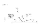
Fig. 5 is a side view which covers the lamination roller, the camera and the lighting ofFig. 3 . -
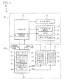
Fig. 6 is a block diagram which shows the device for producing composite material components in the first embodiment of the present invention. -
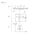
Fig. 7 shows a case where no tape which has already been attached near a tape in the process of attachment exists. (a) is a cross-sectional view of a certain site of the tape in the process of attachment, (b) is a view which shows an image of the site, and (c) is a view which shows brightness distribution at the image. -
Fig. 8 shows a case where a tape which has already been attached and which is adjacent to a tape in the process of attachment exists. (a) is a cross-sectional view of a site when a gap exists between the tape in the process of attachment and the tape which has already been attached, (b) is a view which shows an image of the site, and (c) is a view which shows brightness distribution at the image. -
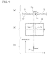
Fig. 9 shows a case where a tape which has already been attached and which is adjacent to a tape in the process of attachment exists. (a) is a cross-sectional view of a site when the tape in the process of attachment overlaps with the tape which has already been attached, (b) is a view which shows an image of the site, and (c) is a view which shows brightness distribution at the image. -
Fig. 10(a), (b), (c), (d) and (e) respectively show the lamination head in preparation for attachment, the lamination head at the start of attachment, the lamination head in the process of attachment, the lamination head on completion of attachment, and the lamination head on standby for attachment. -
Fig. 11 shows inspection data obtained when it is determined that a gap exists at all of the plurality of sites from an attachment starting site to an attachment ending site of a tape. -
Fig. 12 shows inspection data obtained when it is determined that a gap exists at a certain site of the plurality of sites from the attachment starting site to the attachment ending site of the tape and that overlapping exists at other sites. -
Fig. 13 shows inspection data obtained when it is determined that overlapping exists at all of the plurality of sites from the attachment starting site to the attachment ending site of the tape. - With reference to the attached drawings, hereinafter, a description will be given of embodiments in carrying out the method for producing composite material components, the device for producing composite material components, and the inspection device in the present invention.
- A description will be given of a device for producing
composite material components 10 in the first embodiment of the present invention with reference toFig. 1 . The device for producingcomposite material components 10 produces composite material components by laminating a fiber-reinforced plastic tape. The device for producingcomposite material components 10 is provided with a drivingdevice 22 and alamination head 23. An X axis, a Y axis and a Z axis which are orthogonal to each other are defined with regard to the device for producingcomposite material components 10. The Z axis is an axis which faces upward perpendicularly. The drivingdevice 22 drives thelamination head 23 in a translational manner so as to be parallel to the X axis and also parallel to the Y axis. - In
Fig. 2 , the drivingdevice 22 drives thelamination head 23 in a translational manner so as to be parallel to the Z axis and also drives thelamination head 23 in a rotational manner around a rotation axis S1parallel to the Z axis. The drivingdevice 22 is provided with three servo mechanisms corresponding respectively to the above-described three types of translational driving and a servo mechanism corresponding to the above-described rotational driving. - In
Fig. 3 , thelamination head 23 is driven by the drivingdevice 22 and moves with respect to anattachment object 60. Thelamination head 23 attaches a fiber-reinforcedplastic tape 70 to theattachment object 60, while moving. Here, theattachment object 60 is a mold or a laminated body of fiber-reinforced plastic tape laminated on the mold. Thelamination head 23 is provided with a tape-supplyingdevice 24, acutter 25 and alamination roller 26. Twocamera units 31 are mounted on thelamination head 23. The tape-supplyingdevice 24 feeds out thetape 70. Thelamination roller 26 presses and attaches the fed-outtape 70 to theattachment object 60. - In
Fig. 4 , thelamination roller 26 presses thetape 70 to theattachment object 60, while rotating around a rotation axis S2 and rolling on thetape 70. The rotation axis S2 is perpendicular to therotation axis S 1 and parallel to the width direction of thetape 70. Thetape 70 is provided on both sides in the width direction respectively with aside end 70a and a 70b. The twocamera units 31 are arranged on the rear side in a direction at which thelamination head 23 moves with respect to the lamination roller 26 (an advancement direction) so as to photograph an attachment state of thetape 70. These twocamera units 31 are arranged at positions such that they correspond respectively to the side ends 70a and 70b. Hereinafter, there is a case where thecamera unit 31 corresponding to theside end 70a is referred to as a left-side camera unit 31. And, there is a case where thecamera unit 31 corresponding to theside end 70b is referred to as a right-side camera unit 31. The left-side camera unit 31 is provided with acamera 32 which is arranged directly above theside end 70a and faces theside end 70a, alighting 33 which is arranged at a position deviated outside in the width direction of thetape 70 from directly above theside end 70a and also facing theside end 70a, and alighting 33 which is arranged at a position deviated inside in the width direction of thetape 70 from directly above theside end 70a and also facing theside end 70a. The right-side camera unit 31 is provided with acamera 32 which is arranged directly above theside end 70b and faces theside end 70b, alighting 33 which is arranged at a position deviated outside in the width direction of thetape 70 from directly above theside end 70b and also facing theside end 70b, and alighting 33 which is arranged at a position deviated inside in the width direction of thetape 70 from directly above theside end 70b and also facing theside end 70a. That is, thelightings 33 are arranged at positions deviated along a straight line parallel to the rotation axis S2 from directly above the side ends 70a and 70b. Thecamera 32 is, for example, a CCD (charge-coupled device) camera. A light axis of thecamera 32 is parallel to the Z axis. Thelightings 33 are, for example, LED (light-emitting diode) lightings. - As described above, since the
lightings 33 irradiate light obliquely at a fiber-reinforced plastic tape, the side ends of the fiber-reinforced plastic tape are highlighted at an image photographed by thecamera units 31. - The
side end 70a is included in a photographing range of the left-side camera unit 31 but not included in a photographing range of the right-side camera unit 31. Theside end 70b is included in the photographing range of the right-side camera unit 31 but not included in the photographing range of the left-side camera unit 31. - In
Fig. 5 , thecamera 32 and thelighting 33 are arranged in such a manner that a distance between thecamera 32 and thetape 70 in the Z axis direction is greater than a distance between thelighting 33 and the tape in the Z axis direction. - In
Fig. 6 , the device for producingcomposite material components 10 is provided with anautomatic lamination device 20 and aninspection device 30. Theautomatic lamination device 20 is provided with acontroller 21, in addition to the already-describeddriving device 22 and thelamination head 23. Theinspection device 30 is provided with aninformation processing device 34 as a computer for inspection, in addition to the already-described twocamera units 31. Theinformation processing device 34 is provided with aninput device 35, anoutput device 36, aprocessor 37, and astorage device 38. - The
automatic lamination device 20 carries out lamination of fiber-reinforced plastic tape according to the lamination program (lamination procedures) 27. Thecontroller 21 controls the drivingdevice 22, the tape-supplyingdevice 24, and thecutter 25 in order to carry out lamination of the fiber-reinforced plastic tape on the basis of the lamination program 27. Thecontroller 21 controls the drivingdevice 22 in such a manner that during attachment of thetape 70, the rotation axis S2 of thelamination roller 26 is made perpendicular to a direction at which thelamination head 23 moves. Further, thecontroller 21 outputs to theinspection device 30 an operating state notifying signal for notifying an operating state of theautomatic lamination device 20. - The
inspection device 30 determines an attachment state of the fiber-reinforced plastic tape attached by theautomatic lamination device 20 on the basis of an image photographed by thecamera 32, thereby generatinginspection data 40 which shows the results of the determination. Thestorage device 38 stores theinspection data 40. Theinspection device 30 determines whether or not the fiber-reinforced plastic tape is properly attached on the basis of theinspection data 40, thereby outputting an inspection result signal which shows the results of the determination. - The
automatic lamination device 20 stops or continues lamination of the fiber-reinforced plastic tape on the basis of the inspection result signal. - Here, the lamination program 27 stipulates that tapes arranged on the same layer of composite material components are attached so as to be parallel to each other and that the tapes to be arranged on the same layer will not overlap with each other. Hereinafter, this point will be described in detail. As shown in
Fig. 7(a) , there is a case where the lamination program 27 stipulates that no fiber-reinforced plastic tape which is arranged on the same layer as that of thetape 70 in the photographing range of the left-side camera unit 31 exists. Here, the case where the lamination program 27 stipulates that no fiber-reinforced plastic tape which is arranged on the same layer as that of thetape 70 in the photographing range of the left-side camera unit 31 exists is, for example, a case where the lamination program 27 gives instructions to theautomatic lamination device 20 that all the fiber-reinforced plastic tape to be arranged on a certain layer is attached in such a manner that, of all the fiber-reinforced plastic tape arranged on the certain layer of composite material components, thetape 70 is positioned at the extreme end and also other tape is all positioned on theside end 70b side of thetape 70. As shown inFig. 8(a) , there is a case where the lamination program 27 stipulates that a fiber-reinforcedplastic tape 71 to be arranged on the same layer as that of thetape 70 exists on theside end 70a side of thetape 70 and also that a gap having a predetermined dimension (a gap amount) between theside end 71b of thetape 71 on the side of thetape 70 and theside end 70a is provided. In this case, a predetermined gap amount is set to be a value such that both of theside end 70a and theside end 71b exist in the photographing range of the left-side camera unit 31. However, as shown inFig. 9(a) , the lamination program 27 does not stipulate that the fiber-reinforcedplastic tape 71 to be arranged on the same layer as that of thetape 70 exists on theside end 70a side of thetape 70 and that thetape 70 and thetape 71 overlap with each other. - As shown in
Fig. 7(a) , a description will be given of a case where attachment is carried out in such a manner that no fiber-reinforced plastic tape other than thetape 70 exists in the photographing range of the left-side camera unit 31. As shown inFig. 7(b) , no side end other than theside end 70a is taken at animage 51 photographed by thecamera 32 of the left-side camera unit 31. The W axis of theimage 51 is parallel to the width direction of thetape 70.Fig. 7(c) shows brightness distribution on the W axis of theimage 51. The brightness distribution only has a rise (peak) corresponding to theside end 70a. - As shown in
Fig. 8(a) , a description will be given of a case where attachment is carried out in such a manner that thetape 70 and thetape 71 exists in the photographing range of the left-side camera unit 31 and a gap is provided between thetape 70 and thetape 71. As shown inFig. 8(b) , the side ends 70a and 71b are taken at animage 52 photographed by thecamera 32 of the left-side camera unit 31. The W axis of theimage 52 is parallel to the width direction of thetape 70.Fig. 8(c) shows brightness distribution on the W axis of theimage 52. The brightness distribution has a rise corresponding to theside end 70a and a rise corresponding to theside end 71 b. - As shown in
Fig. 9(a) , a description will be given of a case where attachment is carried out in such a manner that thetape 70 overlaps with thetape 71 in the photographing range of the left-side camera unit 31. When thetape 71 is attached before thetape 70, as shown inFig. 9(a) , theside end 70a is arranged on thetape 71, while theside end 71b is arranged under thetape 70. As shown inFig. 9(b) , only theside end 70a is taken at animage 53 photographed by thecamera 32 of the left-side camera unit 31, while theside end 71b is not taken since it is under thetape 70. The W axis of theimage 53 is parallel to the width direction of thetape 70.Fig. 9(c) shows brightness distribution on the W axis of theimage 53. The brightness distribution has only a rise corresponding to theside end 70a. - As shown in
Fig. 7(c) andFig. 9(c) , theprocessor 37 determines that when there is one rise in brightness detected from an image, thetape 70 overlaps with the other tape at a site at which the image is photographed. As shown inFig. 8(c) , theprocessor 37 determines that when there are two rises in brightness detected from an image, a gap exists between thetape 70 and a tape adjacent to thetape 70 at a site at which the image is photographed and calculates a gap amount on the basis of a distance P between the two rises. Here, it is possible to detect a rise in brightness by using a generally known method for detecting edges. - A description can be made similarly as described above even in a case where no fiber-reinforced plastic tape exists other than the
tape 70 in the photographing range of the right-side camera unit 31 and vice versa. - With reference to
Fig. 10 , a description will be given of a method for producing composite material components which is carried out by the device for producingcomposite material components 10. - An
automatic lamination device 20 laminates a fiber-reinforced plastic tape in accordance with a lamination program 27.Fig.10 (a) shows a state in preparation for lamination when the lamination is in progress. In this instance, alamination head 23 is arranged so as to be apart from anattachment object 60. - A
controller 21 allows thelamination head 23 to move in the Z axis direction by using adriving device 22, thereby holding an attachment starting site of atape 70 between alamination roller 26 and theattachment object 60.Fig. 10(b) shows the above-described state. - After the
controller 21 outputs an attachment starting signal as an operating state notifying signal, theautomatic lamination device 20 starts to attach thetape 70. During attachment of thetape 70, thecontroller 10 drives the drivingdevice 22 by controlling a value in such a manner that thelamination head 23 moves on a path designated by the lamination program 27. During attachment of thetape 70, the tape-supplyingdevice 24 feeds out thetape 70, and thelamination roller 26 presses and attaches the fed-outtape 70 to theattachment object 60. During attachment of thetape 70, thecontroller 21 outputs an operating state signal which shows X, Y, Z coordinates of thelamination head 23 at regular time intervals.Fig. 10 (c) shows a state where attachment of thetape 70 is in progress. - The
controller 21 stops the movement of thelamination head 23 by using thedriving device 22 when thelamination head 23 arrives at an attachment ending position designated by the lamination program 27, cuts thetape 70 by using acutter 25 and outputs an attachment ending signal. In this instance, an attachment ending site of thetape 70 is held between thelamination roller 26 and theattachment object 60.Fig. 10(d) shows a state that thelamination head 23 stops at an attachment ending position. - The
controller 21 allows thelamination head 23 to move in the Z axis direction by using thedriving device 22, by which thelamination head 23 is kept at a stand-by position away from theattachment object 60.Fig. 10(e) shows a state where thelamination head 23 is kept at the stand-by position. Thecontroller 21 waits for an inspection result signal from theinspection device 30, with thelamination head 23 kept at the stand-by position. - A description will be given of motions of the
inspection device 30 during attachment of atape 70. Thecamera 32 starts photographing at regular time intervals in response to an attachment starting signal and finishes photographing in response to an attachment ending signal. Thereby, thecamera 32 takes photographs of the respective images at a plurality of sites V1 to Vn from an attachment starting site V1 to an attachment ending site Vn of thetape 70, thereby photographing a plurality of images. Theprocessor 37 calculates a distance D between each of the plurality of sites and the attachment starting site V1 on the basis of the operating state signal which shows the X, Y, Z coordinates of thelamination head 23. Further, theprocessor 37 detects a rise in brightness from each image of the plurality of images at the plurality of sites V1 to Vn and determines whether or not thetape 70 overlaps with the other tape or a gap exists between thetape 70 and the other tape on the basis of the number of rises in brightness detected from each image. Theprocessor 37 determines that thetape 70 overlaps with the other tape, when the number of rises in brightness is one. Theprocessor 37 determines that a gap exists between thetape 70 and the other tape, when the number of rises in brightness is two. When the number of rises in brightness is two (a gap is determined to exist), theprocessor 37 calculates a gap amount G between thetape 70 and the other tape on the basis of a distance between the rises in brightness. - The
processor 37 generatesinspection data 40 and stores the data at astorage device 38. With regard to all the plurality of sites V1 to Vn from the attachment starting site V1 to the attachment ending site Vn of thetape 70, theinspection data 40 shows a distance D from an attachment starting site V1, results of the determination on overlapping or existence of a gap, and a gap amount G on determination of existence of the gap. Theprocessor 37 determines whether or not thetape 70 is attached properly on the basis of theinspection data 40 and outputs an inspection result signal showing the results of the determination. -
Fig. 11 shows theinspection data 40 when it is determined that a gap exists at all of the plurality of sites V1 to Vn from the attachment starting site V1 to the attachment ending site Vn of thetape 70. Theinspection data 40 shows that a gap (GAP) exists and a gap amount is G1 to Gn at each of the plurality of sites V1 to Vn, a distance of which from the attachment startingsite V 1 isD 1 to Dn. Here, a site at which a distance from the attachment starting site V1 is D1 (=0) is the attachment starting site V1, and a site at which a distance from the attachment starting site V1 is Dn is an attachment ending site Vn. As shown inFig. 11 , when it is determined that a gap exists at all of the plurality of sites V1 to Vn from the attachment starting site V1 to the attachment ending site Vn of thetape 70, theprocessor 37 compares each of the gap amounts G1 to Gn with a predetermined threshold value. When all of the gap amounts G1 to Gn are smaller than the predetermined threshold value, theprocessor 37 determines that thetape 70 has been properly attached and outputs a lamination continuing signal as an inspection result signal. When at least any one of the gap amounts G1 to Gn is greater than the predetermined threshold value, theprocessor 37 determines that thetape 70 has not been properly attached and outputs a lamination stopping signal as an inspection result signal. -
Fig. 12 shows theinspection data 40 when it is determined that a gap exists at sites V1, V2, Vn, each distance of which from the attachment starting site V1 is D1, D2, Dn at the plurality of sites V1 to Vn from the attachment starting site V1 to the attachment ending site Vn of thetape 70 and that overlapping (LAP) exists at the sites V3,V4, each distance of which from the attachment starting site V1 is D3, D4 among the plurality of sites V1 to Vn. As shown inFig. 12 , when it is determined that a gap exists at one site of thetape 70 and overlapping exists at other sites, theinspection device 37 determines that thetape 70 has not been properly attached and outputs a lamination stopping signal as an inspection result signal. -
Fig. 13 shows theinspection data 40 when it is determined that overlapping exists at all of the plurality of sites from an attachment starting site to an attachment ending site of thetape 70. Here, as described above, the lamination program 27 stipulates that tape to be arranged on the same layer of composite material components will not overlap with each other. Thus, it is much less likely that thetape 70 overlaps with the other tape at all of the plurality of sites V1 to Vn from an attachment starting site V1 to an attachment ending site Vn. Therefore, when it is determined that overlapping exists at all of the plurality of sites as shown inFig. 13 , the lamination program 27 is considered to stipulate that no fiber-reinforced plastic tape to be arranged on the same layer as that of thetape 70 exists in the photographing range of thecamera 32. When it is determined that overlapping exists at all of the plurality of sites V1 to Vn from the attachment starting site V1 to the attachment ending site Vn of thetape 70 as shown inFig. 13 , theprocessor 37 determines that thetape 70 has been properly attached and outputs a lamination continuing signal as an inspection result signal. - The
automatic lamination device 20 continues to laminate a fiber-reinforced plastic tape on the basis of the lamination continuing signal. In this instance, thecontroller 21 allows thelamination head 23 to move from a stand-by position on the basis of the lamination continuing signal in order to attach a next tape. - The
automatic lamination device 20 stops lamination of the fiber-reinforced plastic tape on the basis of the lamination stopping signal. In this instance, an operator determines visually an attachment state of thetape 70 and operates theautomatic lamination device 20 for attaching thetape 70 again when re-attachment is necessary. When the re-attachment is not necessary, the operator operates theautomatic lamination device 20 to attach a next tape. - In the present embodiment, when it is determined that overlapping exists at all of the plurality of sites V1 to Vn as shown in
Fig. 13 , it is possible to prevent unnecessary stopping of laminating thetape 70 that is properly attached according to the lamination program 27 due to an incorrect determination "improper" being made of an attachment state of thetape 70. - The present embodiment can be modified in various ways.
- For example, in place of the above-described method for determining the overlapping of tape or the existence of a gap on the basis of rises in brightness to calculate a gap amount, a method in which the overlapping or the existence of a gap is determined to calculate a gap amount on the basis of measurement results obtained by using line laser is available.
- Further, in place of the above-described method in which the
inspection device 30 automatically outputs a lamination continuing signal or a lamination stopping signal on the basis of theinspection data 40, it is possible to use the following method. In this method, anoutput device 36 outputs resultdata 40. An operator determines whether or not thetape 70 has been properly attached on the basis of theoutput result data 40 and operates aninput device 35, thereby allowing aninspection device 30 to output a lamination continuing signal or a lamination stopping signal. - A description has been so far made of a preferred embodiment of the present invention, although the present invention shall not be limited thereto. The present invention may be subjected to addition of the configuration, omission, replacement and other modifications within a scope not departing from the gist of the present invention. The present invention shall not be limited to the above description, but will be limited only by the scope of the attached claims.
- According to the method for producing composite material components, the device for producing composite material components and the inspection device of the present invention, it is possible to prevent an incorrect determination "improper" being made of an attachment state of a fiber-reinforced plastic tape which has been properly attached.
-
- 10: Device for producing composite material components
- 20: Automatic lamination device
- 21: Controller
- 22: Driving device
- 23: Lamination head
- 24: Tape-supplying device
- 25: Cutter
- 26: Lamination roller
- 27: Lamination program
- 30: Inspection device
- 31: Camera unit
- 32: Camera
- 33: Lighting
- 34: Information processing device
- 35: Input device
- 36: Output device
- 37: Processor
- 38: Storage device
- 40: Inspection data
- 51: Image
- 52: Image
- 53: Image
- 60: Attachment object (mold or laminated body)
- 70: Tape
- 71: Tape
- 70a: Side end
- 70b: Side end
- 71b: Side end
- S 1: Rotation axis of lamination head
- S2: Rotation axis of lamination roller
Claims (13)
- A method for producing composite material components which has a process of laminating fiber-reinforced plastic tape,
the method for producing the composite material components including, determining an attachment state of a first fiber-reinforced plastic tape during lamination of the fiber-reinforced plastic tape at a plurality of sites from an attachment starting site to an attachment ending site of the first fiber-reinforced plastic tape, wherein
the lamination is stopped when it is determined that the first fiber-reinforced plastic tape overlaps with a second fiber-reinforced plastic tape at a first site of the plurality of sites and that a gap exists between the first fiber-reinforced plastic tape and the second fiber-reinforced plastic tape at a second site of the plurality of sites, and
the lamination is continued when it is determined that the first fiber-reinforced plastic tape overlaps with the second fiber-reinforced plastic tape at all of the plurality of sites. - The method for producing the composite material components according to Claim 1, wherein
determining the attachment state includes,
taking a photograph of each image at the plurality of sites by a camera mounted on a lamination head which attaches the first fiber-reinforced plastic tape while moving, thereby taking photographs of a plurality of images; and
determining whether or not the first fiber-reinforced plastic tape overlaps with the second fiber-reinforced plastic tape or a gap exists between the first fiber-reinforced plastic tape and the second fiber-reinforced plastic tape on the basis of the number of rises in brightness detected from each image of the plurality of images at the plurality of sites. - The method for producing the composite material components according to Claim 2, wherein
determining the attachment state includes,
calculating a gap amount between the first fiber-reinforced plastic tape and the second fiber-reinforced plastic tape on the basis of a distance between the rises in brightness when the number of rises in brightness is two. - The method for producing the composite material components according to Claim 3, wherein
the lamination is stopped when it is determined that a gap exists between the first fiber-reinforced plastic tape and the second fiber-reinforced plastic tape at all of the plurality of sites and that the gap amount between the first fiber-reinforced plastic tape and the second fiber-reinforced plastic tape is greater than a predetermined threshold value at least at one of the plurality of sites. - The method for producing the composite material components according to any one of Claim 1 to Claim 4, wherein
the lamination is carried out in accordance with a lamination program which stipulates that the fiber-reinforced plastic tapes to be arranged on the same layer will not overlap with each other. - A device for producing composite material components comprising:an automatic lamination device which carries out lamination of fiber-reinforced plastic tape; andan inspection device which determines an attachment state of a first fiber-reinforced plastic tape at a plurality of sites from an attachment starting site to an attachment ending site of the first fiber-reinforced plastic tape attached by the automatic lamination device during the lamination, whereinthe automatic lamination device stops the lamination when the inspection device determines that the first fiber-reinforced plastic tape overlaps with a second fiber-reinforced plastic tape at a first site of the plurality of sites and also determines that a gap exists between the first fiber-reinforced plastic tape and the second fiber-reinforced plastic tape at a second site of the plurality of sites, andthe automatic lamination device continues the lamination when the inspection device determines that the first fiber-reinforced plastic tape overlaps with the second fiber-reinforced plastic tape at all of the plurality of sites.
- The device for producing the composite material components according to Claim 6, wherein
the automatic lamination device is provided with a lamination head which attaches the first fiber-reinforced plastic tape while moving,
the inspection device is provided with a camera mounted on the lamination head, the camera takes a photograph of each image at the plurality of sites, thereby taking photographs of a plurality of images, and
the inspection device determines whether or not the first fiber-reinforced plastic tape overlaps with the second fiber-reinforced plastic tape or a gap exists between the first fiber-reinforced plastic tape and the second fiber-reinforced plastic tape on the basis of the number of rises in brightness detected from each image of the plurality of images at the plurality of sites. - The device for producing the composite material components according to Claim 7, wherein
when the number of rises in brightness is two, the inspection device calculates a gap amount between the first fiber-reinforced plastic tape and the second fiber-reinforced plastic tape on the basis of a distance between the rises in brightness. - The device for producing the composite material components according to Claim 8, wherein
the automatic lamination device stops the lamination when it is determined that a gap exists between the first fiber-reinforced plastic tape and the second fiber-reinforced plastic tape at all of the plurality of sites and that a gap amount between the first fiber-reinforced plastic tape and the second fiber-reinforced plastic tape is greater than a predetermined threshold value at least at one of the plurality of sites. - The device for producing the composite material components according to any one of Claim 6 to Claim 9, wherein
the automatic lamination device carries out the lamination in accordance with a lamination program which stipulates that fiber-reinforced plastic tape to be arranged on the same layer will not overlap with each other. - The device for producing the composite material components according to any one of Claim 6 to Claim 10, wherein
the inspection device is provided with a lighting,
the camera is mounted on the lamination head in such a manner as to be arranged directly above a side end of the first fiber-reinforced plastic tape and also face the side end, and
the lighting is mounted on the lamination head in such a manner as to be arranged at a position deviated in a width direction of the first fiber-reinforced plastic tape from directly above the side end and also face the side end. - An inspection device comprising:a camera mounted on a lamination head of an automatic lamination device which carries out lamination of fiber-reinforced plastic tape; andan information processing device, whereinthe lamination head attaches a first fiber-reinforced plastic tape while moving during the lamination andthe information processing device determines an attachment state of the first fiber-reinforced plastic tape at a plurality of sites of the first fiber-reinforced plastic tape on the basis of a plurality of images photographed by the camera and outputs a lamination stopping signal or a lamination continuing signal on the basis of results determined regarding the attachment state.
- The inspection device according to Claim 12, wherein
the information processing device outputs the lamination stopping signal when it is determined that the first fiber-reinforced plastic tape overlaps with the second fiber-reinforced plastic tape at the first sites of the plurality of sites and that a gap exists between the first fiber-reinforced plastic tape and the second fiber-reinforced plastic tape at the second sites of the plurality of sites, and
the information processing device outputs the lamination continuing signal when it is determined that the first fiber-reinforced plastic tape overlaps with the second fiber-reinforced plastic tape at all of the plurality of sites.
Applications Claiming Priority (2)
| Application Number | Priority Date | Filing Date | Title |
|---|---|---|---|
| JP2009263293A JP2011104905A (en) | 2009-11-18 | 2009-11-18 | Method and apparatus for producing composite material parts and inspection apparatus |
| PCT/JP2010/070462 WO2011062180A1 (en) | 2009-11-18 | 2010-11-17 | Method for producing composite material components, device for producing composite material components, and inspection device |
Publications (1)
| Publication Number | Publication Date |
|---|---|
| EP2502732A1 true EP2502732A1 (en) | 2012-09-26 |
Family
ID=44059658
Family Applications (1)
| Application Number | Title | Priority Date | Filing Date |
|---|---|---|---|
| EP10831574A Withdrawn EP2502732A1 (en) | 2009-11-18 | 2010-11-17 | Method for producing composite material components, device for producing composite material components, and inspection device |
Country Status (4)
| Country | Link |
|---|---|
| US (1) | US20120147175A1 (en) |
| EP (1) | EP2502732A1 (en) |
| JP (1) | JP2011104905A (en) |
| WO (1) | WO2011062180A1 (en) |
Families Citing this family (4)
| Publication number | Priority date | Publication date | Assignee | Title |
|---|---|---|---|---|
| FR2975940A1 (en) * | 2011-05-31 | 2012-12-07 | Forest Line Capdenac | METHOD FOR CONTROLLING THE PLAY BETWEEN BANDS DEPOSITED BY A DRAPING HEAD AND SUB-ASSEMBLY OF A DRAPING HEAD WITH A BOOT CONTROL DEVICE. |
| JP5805550B2 (en) | 2012-01-30 | 2015-11-04 | 富士重工業株式会社 | Pre-preg sticking state inspection device |
| US8983171B2 (en) * | 2012-12-26 | 2015-03-17 | Israel Aerospace Industries Ltd. | System and method for inspecting structures formed of composite materials during the fabrication thereof |
| US10549491B2 (en) * | 2017-09-06 | 2020-02-04 | The Boeing Company | System and method for edge length differential measurement for fiber steering in automated fiber placement |
Family Cites Families (6)
| Publication number | Priority date | Publication date | Assignee | Title |
|---|---|---|---|---|
| US4920738A (en) * | 1987-03-31 | 1990-05-01 | The Boeing Company | Apparatus for winding optical fiber on a bobbin |
| JPH0818378B2 (en) * | 1992-08-07 | 1996-02-28 | 東芝機械株式会社 | Laminating equipment for prepreg |
| US5963660A (en) * | 1996-09-26 | 1999-10-05 | The Boeing Company | Method and apparatus for detecting and measuring laps and gaps in composite materials |
| US7039485B2 (en) * | 2004-03-12 | 2006-05-02 | The Boeing Company | Systems and methods enabling automated return to and/or repair of defects with a material placement machine |
| US7766063B2 (en) * | 2005-04-28 | 2010-08-03 | The Boeing Company | Machine assisted laminator and method |
| JP4691562B2 (en) * | 2005-11-07 | 2011-06-01 | 富士通株式会社 | Lamination state inspection device, lamination state inspection method, and lamination state detection program |
-
2009
- 2009-11-18 JP JP2009263293A patent/JP2011104905A/en not_active Withdrawn
-
2010
- 2010-11-17 WO PCT/JP2010/070462 patent/WO2011062180A1/en not_active Ceased
- 2010-11-17 EP EP10831574A patent/EP2502732A1/en not_active Withdrawn
- 2010-11-17 US US13/386,728 patent/US20120147175A1/en not_active Abandoned
Non-Patent Citations (1)
| Title |
|---|
| See references of WO2011062180A1 * |
Also Published As
| Publication number | Publication date |
|---|---|
| WO2011062180A1 (en) | 2011-05-26 |
| JP2011104905A (en) | 2011-06-02 |
| US20120147175A1 (en) | 2012-06-14 |
Similar Documents
| Publication | Publication Date | Title |
|---|---|---|
| US20120120228A1 (en) | Inspection method, method for producing composite material components, inspection device, and device for producing composite material components | |
| JP5805550B2 (en) | Pre-preg sticking state inspection device | |
| EP2749869B1 (en) | System and method for inspecting structures formed of composite materials during the fabrication thereof | |
| US10925200B2 (en) | Mounting processing method, mounting system, exchange control device, and component mounter | |
| ES2337290T3 (en) | ROLLER ASSISTED BY MACHINE AND METHOD. | |
| US20120147175A1 (en) | Method for producing composite material components, device for producing composite material components, and inspection device | |
| US20110306263A1 (en) | Method for aligning film sheets and rectangular panels in display panel manufacturing system | |
| JP5881244B2 (en) | Component mounting apparatus, board detection method, and board manufacturing method | |
| KR101476710B1 (en) | Cutting device and cutting method thereof | |
| JP2023014352A (en) | Double-sided exposure device and double-sided exposure method | |
| EP3270677B1 (en) | Mounting device, image processing method and imaging unit | |
| CN101149249A (en) | Measuring method of image measuring instrument | |
| KR101219087B1 (en) | Slitting machine of display panel for thin film and cutting method using the same | |
| JP2007310209A (en) | Exposure equipment | |
| JP2008003080A (en) | System and method for measuring plate material width | |
| JP5022507B1 (en) | Product panel continuous manufacturing method, detection system, and detection method | |
| EP1947417B1 (en) | Lamination status inspecting apparatus, lamination status inspecting method and lamination status detecting program | |
| CN107145127B (en) | A kind of method and system based on the asynchronous vision positioning flight processing of double end | |
| JP5168576B2 (en) | Method and apparatus for cutting strip member | |
| JPWO2015052755A1 (en) | Mounting device | |
| WO2014127377A1 (en) | Improved system and method for manufacturing flexible laminated circuit boards | |
| KR101476711B1 (en) | Cutting method | |
| JP5102496B2 (en) | Flat cable slitting method and apparatus | |
| EP4037447B1 (en) | Periphery monitoring device | |
| JP2016224842A (en) | Automatic traveling vehicle |
Legal Events
| Date | Code | Title | Description |
|---|---|---|---|
| PUAI | Public reference made under article 153(3) epc to a published international application that has entered the european phase |
Free format text: ORIGINAL CODE: 0009012 |
|
| 17P | Request for examination filed |
Effective date: 20120126 |
|
| AK | Designated contracting states |
Kind code of ref document: A1 Designated state(s): AL AT BE BG CH CY CZ DE DK EE ES FI FR GB GR HR HU IE IS IT LI LT LU LV MC MK MT NL NO PL PT RO RS SE SI SK SM TR |
|
| DAX | Request for extension of the european patent (deleted) | ||
| STAA | Information on the status of an ep patent application or granted ep patent |
Free format text: STATUS: THE APPLICATION HAS BEEN WITHDRAWN |
|
| 18W | Application withdrawn |
Effective date: 20131230 |