EP2501600B1 - Bremsanzeige - Google Patents
Bremsanzeige Download PDFInfo
- Publication number
- EP2501600B1 EP2501600B1 EP10831878.3A EP10831878A EP2501600B1 EP 2501600 B1 EP2501600 B1 EP 2501600B1 EP 10831878 A EP10831878 A EP 10831878A EP 2501600 B1 EP2501600 B1 EP 2501600B1
- Authority
- EP
- European Patent Office
- Prior art keywords
- brake
- indicator
- parking brake
- transmitter
- braking force
- Prior art date
- Legal status (The legal status is an assumption and is not a legal conclusion. Google has not performed a legal analysis and makes no representation as to the accuracy of the status listed.)
- Active
Links
Images



Classifications
-
- B—PERFORMING OPERATIONS; TRANSPORTING
- B60—VEHICLES IN GENERAL
- B60T—VEHICLE BRAKE CONTROL SYSTEMS OR PARTS THEREOF; BRAKE CONTROL SYSTEMS OR PARTS THEREOF, IN GENERAL; ARRANGEMENT OF BRAKING ELEMENTS ON VEHICLES IN GENERAL; PORTABLE DEVICES FOR PREVENTING UNWANTED MOVEMENT OF VEHICLES; VEHICLE MODIFICATIONS TO FACILITATE COOLING OF BRAKES
- B60T17/00—Component parts, details, or accessories of power brake systems not covered by groups B60T8/00, B60T13/00 or B60T15/00, or presenting other characteristic features
- B60T17/18—Safety devices; Monitoring
- B60T17/22—Devices for monitoring or checking brake systems; Signal devices
- B60T17/221—Procedure or apparatus for checking or keeping in a correct functioning condition of brake systems
-
- B—PERFORMING OPERATIONS; TRANSPORTING
- B60—VEHICLES IN GENERAL
- B60T—VEHICLE BRAKE CONTROL SYSTEMS OR PARTS THEREOF; BRAKE CONTROL SYSTEMS OR PARTS THEREOF, IN GENERAL; ARRANGEMENT OF BRAKING ELEMENTS ON VEHICLES IN GENERAL; PORTABLE DEVICES FOR PREVENTING UNWANTED MOVEMENT OF VEHICLES; VEHICLE MODIFICATIONS TO FACILITATE COOLING OF BRAKES
- B60T17/00—Component parts, details, or accessories of power brake systems not covered by groups B60T8/00, B60T13/00 or B60T15/00, or presenting other characteristic features
- B60T17/18—Safety devices; Monitoring
- B60T17/22—Devices for monitoring or checking brake systems; Signal devices
- B60T17/228—Devices for monitoring or checking brake systems; Signal devices for railway vehicles
-
- B—PERFORMING OPERATIONS; TRANSPORTING
- B61—RAILWAYS
- B61H—BRAKES OR OTHER RETARDING DEVICES SPECIALLY ADAPTED FOR RAIL VEHICLES; ARRANGEMENT OR DISPOSITION THEREOF IN RAIL VEHICLES
- B61H13/00—Actuating rail-vehicle brakes
- B61H13/34—Details
Definitions
- This invention pertains in general to the field of brake indicators for rail vehicles, and in particular to a parking brake indicator for a rail vehicle, such as a train.
- Some of the current parking brake indicators for rail vehicles visually indicate the displacement between a first non braking position and a second assumed braking position of the braking rod applying pressure on the brake blocks.
- Some rail vehicles are equipped with brake blocks that are arranged to move along rail vehicle wheel, depending on the load of the rail vehicle. Hence, when the vehicle is fully loaded the brake blocks are situated towards the lowermost portion of the wheel, and when the vehicle is unloaded the brake blocks are situated more towards the middle or uppermost portion of the wheels. Background art is reflected for instance in US-B-6,082,502 which discloses a brake system indicator.
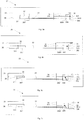
- Fig. 1 illustrates a simple layout of a known parking brake system.
- the brake system comprises a brake transmitter 11 which applies braking force onto a wheel 12, via brake shoes or brake blocks 13, by means of a brake actuator 14, such as a mechanical means applying force on the brake transmitter.
- Figs 2a-2b illustrate such a brake indicator for such a construction in a non-braked mode.
- the brake indicator is connected to a parking brake transmitter 11, comprising an actuator spring 22.
- the parking brake transmitter 11 is arranged to move in its longitudinal direction (left and right in Fig. 2b ) e.g. by means of a mechanical means applying a mechanical force (not shown).
- the mechanical means forces the parking brake transmitter 11 to the left
- the parking brake transmitter 11 evidently applies a braking force against the brake blocks which are arranged adjacently to the wheels.
- the actuator spring 22 is arranged in the brake transmitter 11 in order to enable a braking force towards the brake blocks of the rail vehicle, when the brake blocks are arranged to move along the rail vehicle wheel as mentioned above.
- the actuator spring 22 when the length displacement is maximal in longitudinal direction the actuator spring 22 has been compressed.
- the brake blocks move along the rail vehicle wheel towards the lowermost portion of the rail vehicle wheels.
- the distance between the brake blocks and the mechanical means is extended, and if no actuator spring 22 is available, the amount of braking force applied to the brake blocks decreases, since the length displacement of the brake transmitter is at its fixed value.
- the actuator spring 22 is utilized for applying a braking force on the braking blocks, even when no further length displacement of the brake transmitter 11 is available.
- the brake transmitter is attached to a rigid indicator bar 23.
- the brake indicator further comprises a brake indicator arrangement 24, fixedly mounted to the vehicle construction, and having an indicator 241 which is slidably mounted in a recess 242 in the brake indicator arrangement 24.
- the indicator 241 is attached to the other end of the indicator bar 23.
- the brake indicator arrangement 24 to visualize the braked and non-braked mode, respectively.
- Fig. 2b illustrates the brake indicator in a braked mode in which the parking brake transmitter has been moved longitudinally to the left, thus forcing the indicator 242 to the ON position.
- the present invention seeks to mitigate, alleviate or eliminate one or more of the above-identified deficiencies in the art and disadvantages singly or in any combination and solves at least the above mentioned problems by providing a parking brake indicator system and a rail vehicle according to appended claims 1 and 15, respectively.
- Preferred embodiments are defined in the appended dependent claims 2-14.
- An object is to provide a parking brake indicator system which indicates the actual applied braking force towards the brake system of a rail vehicle.
- a parking brake indicator system for a rail vehicle.
- the parking brake indicator system comprises a movably arranged parking brake transmitter for applying a braking force towards the brake system of a rail vehicle, the parking brake transmitter having provided therein a resilient member which is compressed, when the parking brake transmitter transmits a brake force against a wheel or brake disc of the rail vehicle.
- the parking brake indicator system further comprises a brake indicator arrangement connected to the resilient member, wherein the brake indicator arrangement is configured to indicate when the actual applied braking force of the parking brake transmitter towards the braking system is at a predetermined magnitude and to allow a possibly higher force to be accommodated by the resilient member.
- a parking brake indicator device for connection to a parking brake indicator system.
- the parking brake indicator device comprises a brake indicator arrangement for connection to a resilient member of a brake transmitter, wherein the brake indicator arrangement is configured to indicate when the actual applied braking force of the parking brake transmitter towards the braking system is at a predetermined magnitude and to allow a possibly higher force to be accomodated by the resilient member.
- An idea of the present invention is to provide a parking brake indicator system and device which takes into account only the actual braking force applied on the rail vehicle wheels or discs.
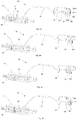
- a parking brake indicator system 30 is provided.
- Figs. 3a to 3b illustrates the parking brake indicator system when no braking force is applied.
- Figs. 3c to 3d illustrate the parking brake indicator system at different applied braking forces, and in Fig. 3d a suitable maximum braking force is indicated by a brake indicator 35.
- the parking brake indicator system 30 comprises a parking brake transmitter 31, which transfers force from e.g. an air cylinder or by mechanical means (not shown) towards the brake system connected to the rail vehicle wheel or disc (not shown).
- the parking brake transmitter 31 comprises a resilient member 32, such as a spring, attached at one end to the housing of the parking brake transmitter 31 and at the other end to the end of a rigid indicator tube 33.
- the other end of the indicator tube 33 is attached to an indicator panel 35, which is visually accessible from the outside of the rail vehicle.
- the indicator panel 35 is slidably mounted into a recess 341 of a brake indicator arrangement 34 which is fixedly mounted in the rail vehicle construction.
- the brake indicator panel 35 follows the movement of the parking brake transmitter 31 as well as the compression and extension of the resilient member 32.
- the indicator tube is directly connected to the end of the resilient member 32, since this enables the indicator panel 35 to move in relation to the brake indicator arrangement 34, and thus the movement of the indicator panel 35 in relation to the brake indicator arrangement 34 both depends on the compression level of the resilient member 32 and the length displacement of the brake transmitter 31. Since a wire 36 in the indicator tube 33 is fixated to the brake transmitter 31 the indicator panel 35 also moves along with the length displacement of the brake transmitter 31.
- the brake indicator 351 starts to rotate, thereby indicating the compression of the resilient member 32, which in turn indicates the applied braking force.
- the brake indicator 351 only indicates the braking force applied on the brake system of the rail vehicle.
- the resilient member 32 may thus be selected such that its spring force is in the same magnitude as the desired braking force to be applied towards the braking system of the rail vehicle.
- the spring force of the resilient member 32 may thus be selected such that it defines the initial braking force level at which the brake blocks start to brake the rail vehicle. When the braking force exceeds this initial braking force level, the resilient member 32 is compressed, whereby the brake indicator 351 rotates further.
- the indicator panel 35 comprises a brake indicator 351, which may be an arrow with the base end 359 rotatably mounted to the indicator panel 35, whereby the arrow may rotate around its base end 359.
- a brake indicator 351 may be an arrow with the base end 359 rotatably mounted to the indicator panel 35, whereby the arrow may rotate around its base end 359.
- any suitable brake indicator may be utilized.
- the parking brake indicator system 30 further comprises a wire 36 which is mounted at one end to the parking brake transmitter 31, as illustrated in Figs. 3a to 3d .
- the wire 36 is preferably made of a sufficiently non-flexible robust material, such as steel. However, any suitable wire may be used.
- the wire 36 may extend through a channel 357 in the rigid indicator tube 33 and is at the other end mounted to the brake indicator 351, by an attachment knob 3512, at a position above the base end of the brake indicator 351.
- the wire may extend through a member 358 protruding from the indicator panel 35, via a hole 358, as is indicated in Fig. 4 which illustrates the brake indicator arrangement in greater detail.
- the member 358 functions to stabilize and align the wire 36 along the indicator panel 35.
- the resilient member 32 When the braking force exceeds the spring force of the resilient member 32, the resilient member 32 begins to compress. During compression of the resilient member 32, i.e. when the brake transmitter is pushed longitudinally (to the left in Figs. 3a to 3d ) the brake transmitter pulls in the wire and thereby rotating the brake indicator 351 around its base end 359, as is illustrated in Figs. 3c and 3d . The rotational direction of the brake indicator 35 then visually indicates the actual braking force being applied by the brake transmitter 31.
- the indicator panel 35 may be provided with an "ON" marking or tag, as is illustrated in Figs. 3a to 3d .
- the "ON" tag in conjunction with the direction of the brake indicator indicates that a suitable braking force is applied.
- the brake indicator arrangement 34 may be provided with an "OFF" tag or marking to indicate when no braking force is applied.
- the brake indicator 351 points towards the "OFF" tag on the brake indicator arrangement, as is illustrated in Fig. 3a .
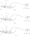
- Figs. 5a to 5d respectively illustrate the parking brake indicator system according to the second embodiment in a more practical design.
- the brake indicator 351 is provided with a slit 3511 in which an attachment knob 3512 is slidably mounted.
- the attachment knob 3512 is attached to the wire 36, and may also slide along a recess 353 provided in the indicator panel 35.
- the function of the attachment knob 3512 is to stabilize the brake indicator 351 to the indicator panel 35, while enabling a constant perpendicular distance between the mounting position of the base end of the brake indicator 351 and the extension of the indicator tube 33, such as to avoid unnecessary bending or wear of the brake indicator 351 in use.
- the indicator tube 33 through which the wire 36 extends, is mounted in a holder 311 which is attached to one end of the resilient member 32.
- the indicator tube 33 may also be directly attached to the resilient member 32 if applicable.
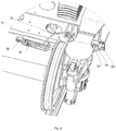
- Fig. 6 illustrates the parking brake indicator system mounted to an existing wheel construction.
- the left side of the brake transmitter 31 is connected to the brake system (not shown) of the rail vehicle, while the right side of the brake transmitter is connected to the air cylinder or mechanical means (not shown).
- Figs. 7a to 7c illustrate a third embodiment of the parking brake indicator system.
- Fig. 7a illustrates the parking brake indicator system when no braking force is applied.
- Fig. 7b illustrates the parking brake indicator system during building up of braking force.
- Fig. 7c illustrates the parking brake indicator system when a suitable maximum braking force is indicated by the brake indicator 3512.
- brake indicator arrangement comprises an indicator panel 35 having a recess 353, being parallel to the extension of the indicator tube 33, into which the attachment knob 3512 is slidably mounted. The attachment knob 3512 is attached to the end of the wire 36.
- the indicator panel is provided with an "ON” tag and an "OFF” tag, and the position of the attachment knob 3512 in relation to the "ON” and "OFF” tags indicates the level of the applied braking force.
- the attachment knob 3512 acts as a brake indicator 351 in accordance with above, except for that attachment knob 3512 does not rotate when the braking force exceeds the spring force of the resilient member.
- the functionality is equal, since the attachment knob 3512 is connected to the resilient member 32, whereby the attachment knob will travel towards the "ON" tag during the compression of the resilient member 32.
- the wire is arranged within a channel of the indicator tube 33, but it is equally possible to arrange the wire separately from the parking brake transmitter 31 to the brake indicator 35, when no channel is provided in the rigid indicator tube 33.
- Figs. 8a to 8c illustrate a fourth embodiment of a parking brake transmitter 81 which is arranged to be visually accessible from the outside of the rail vehicle wagon.
- the parking brake transmitter 81 comprises a resilient member 82, such as a spring.
- the parking brake transmitter 81 comprises an indicator wheel 83 having a threaded hole extended there through, in which threaded hole a brake axis 85 (right side of the brake transmitter) of the parking brake transmitter 81 having a corresponding threaded portion is arranged. Attached to the indicator wheel 83 an indicator lever 84 may be attached.
- a brake axis 85 right side of the brake transmitter
- the left side of the brake transmitter 81 may be connected to the brake system (not shown) of the rail vehicle, while the right side of the brake transmitter may be connected to an air cylinder or mechanical means (not shown).
- the resilient member 82 starts to compress.
- the resilient member is at one side fixedly attached to the brake axis 85, as may be observed in Figs. 8b and 8c , which enables the resilient member to be compressed by means of the air cylinder or mechanical means.
- the resilient member 82 compresses the brake axis 85 with the threaded portion is moved towards the right in Figs. 8a to 8d , whereby the indicator lever 84 rotates indicating the applied braking force.
Landscapes
- Engineering & Computer Science (AREA)
- Mechanical Engineering (AREA)
- Transportation (AREA)
- Braking Arrangements (AREA)
- Braking Elements And Transmission Devices (AREA)
Claims (15)
- Feststellbremsenanzeigesystem (30, 40, 60, 83, 84) für ein Schienenfahrzeug, wobei das System einen Feststellbremsenübertrager (31, 81) und eine Bremsanzeigeanordnung (34, 35, 351, 352, 83, 84) aufweist;
wobei der Feststellbremsenübertrager (31, 81) zum Aufbringen einer Bremskraft in Richtung des Bremssystems des Schienenfahrzeugs beweglich angeordnet ist, wobei in dem Feststellbremsenübertrager ein federnd nachgiebiges Bauteil (32, 82) vorhanden ist, welches zusammengedrückt wird, wenn der Feststellbremsenübertrager eine Bremskraft an ein Rad oder eine Bremsscheibe des Schienenfahrzeugs überträgt;
wobei die Bremsanzeigeanordnung (34, 35, 351, 352, 83, 84) mechanisch ist und mit dem federnd nachgiebigen Bauteil (32, 82) verbunden ist, wobei die Bremsanzeigeanordnung dazu eingerichtet ist, visuell anzuzeigen, wenn das federnd nachgiebige Bauteil (32, 82) zusammengedrückt ist oder wenn somit die tatsächlich aufgebrachte Bremskraft des Feststellbremsenübertragers (31, 81) in Richtung des Bremssystems eine vorbestimmte Größe hat, und zu erlauben, dass das federnd nachgiebige Bauteil (32, 82) eine möglicherweise größere Kraft aufnehmen kann;
wobei der Feststellbremsenübertrager (31, 81) fest an einem Ende eines Drahts (36) angebracht ist, der an seinem anderen Ende fest an einem Bremsanzeiger (351) eines Anzeigefelds (35) angebracht ist; und
wobei das Anzeigefeld (35) verschiebbar auf der Bremsanzeigeanordnung (34) angebracht ist, die feststehend an dem Fahrzeugaufbau befestigt ist;
dadurch gekennzeichnet, dass der Bremsanzeiger (351) an seinem Fußende (359) drehbar an dem Anzeigefeld (35) angebracht ist, eine Drehung um sein Fußende (359) relativ zum Anzeigefeld (35) gestattend. - System nach Anspruch 1, wobei das federnd nachgiebige Bauteil (32) eine Feder ist.
- System nach Anspruch 1 oder 2, wobei der Bremsanzeiger (351) in Gestalt eines Pfeils ausgeführt ist.
- System nach einem der vorhergehenden Ansprüche, wobei der Draht (36) aus einem ausreichend unflexiblen, robusten Material wie beispielsweise Stahl besteht.
- System nach einem der vorhergehenden Ansprüche, wobei der Draht (36) durch ein an dem Anzeigefeld (35) angebrachtes Element (358) verläuft.
- System nach Anspruch 5, wobei das Element (358) mit einer Öffnung (3581) versehen ist, durch die sich der Draht (36) in Richtung des Bremsanzeigers (351) erstreckt.
- System nach einem der vorhergehenden Ansprüche, wobei das Anzeigefeld (35) mit einer "EIN" Markierung oder "AUS" Markierung versehen ist.
- System nach einem der vorhergehenden Ansprüche, wobei der Bremsanzeiger (351) oder das Anzeigefeld (35) mit einem Schlitz (3511) versehen ist, in dem ein Mitnehmerknopf (3512) verschiebbar angebracht ist, wobei der Mitnehmerknopf (3512) an dem Draht (36) befestigt ist.
- System nach Anspruch 8, wobei der Mitnehmerknopf (3512) verschiebbar an einer in dem Anzeigefeld (35) vorhandenen Ausnehmung (353) angebracht ist.
- System nach einem der vorhergehenden Ansprüche, wobei das Anzeigefeld (35) mittels einer Bremsanzeigeaussparung (341) verschiebbar an der Bremsanzeigeanordnung (34) angeordnet ist.
- System nach einem der vorhergehenden Ansprüche, wobei der Draht (36) an dem Feststellbremsenübertrager (31) angebracht ist mittels eines Halters (311), der an einem Ende des federnd nachgiebigen Bauteils (32) angebracht ist.
- System nach Anspruch 9, wobei die Ausnehmung (353) im Wesentlichen parallel zur Erstreckung eines Anzeigerohrs (33) ist, in dem der Mitnehmerknopf (3512) verschiebbar montiert ist.
- System nach Anspruch 12, wobei der Draht (36) von dem Feststellbremsenübertrager (31) durch einen Kanal (357) innerhalb des Anzeigerohrs (33) zum Bremsanzeiger (351) verläuft.
- System nach Anspruch 1, wobei der Feststellbremsenübertrager (81) eine Bremswelle (85) aufweist und ein Feststellbremsenanzeiger (83, 84) mittels eines Gewindeabschnitts mit der Bremswelle (85) verbunden ist, der einem Gewindeabschnitt der Bremswelle (85) entspricht, so dass dann, wenn die Bremswelle (85) in einer Richtung längs ihrer Länge bewegt wird, der Bremsanzeiger (83, 84) um die Bremswelle (85) gedreht wird, um eine Bremskraft anzuzeigen, wobei die Feststellbremsenanzeigeeinrichtung (83, 84) vorzugsweise ein Anzeigerad (83) oder einen Anzeigehebel (84) umfasst.
- Schienenfahrzeug mit einem Feststellbremsenanzeigesystem nach einem der vorhergehenden Ansprüche.
Applications Claiming Priority (3)
| Application Number | Priority Date | Filing Date | Title |
|---|---|---|---|
| SE0950885A SE535038C2 (sv) | 2009-11-20 | 2009-11-20 | Parkeringsbromsindikatorsystem |
| US28536409P | 2009-12-10 | 2009-12-10 | |
| PCT/SE2010/051272 WO2011062552A1 (en) | 2009-11-20 | 2010-11-18 | Brake indicator |
Publications (3)
| Publication Number | Publication Date |
|---|---|
| EP2501600A1 EP2501600A1 (de) | 2012-09-26 |
| EP2501600A4 EP2501600A4 (de) | 2017-04-19 |
| EP2501600B1 true EP2501600B1 (de) | 2020-04-29 |
Family
ID=44059846
Family Applications (1)
| Application Number | Title | Priority Date | Filing Date |
|---|---|---|---|
| EP10831878.3A Active EP2501600B1 (de) | 2009-11-20 | 2010-11-18 | Bremsanzeige |
Country Status (3)
| Country | Link |
|---|---|
| EP (1) | EP2501600B1 (de) |
| SE (1) | SE535038C2 (de) |
| WO (1) | WO2011062552A1 (de) |
Families Citing this family (1)
| Publication number | Priority date | Publication date | Assignee | Title |
|---|---|---|---|---|
| CN102785676B (zh) * | 2012-08-21 | 2015-07-15 | 齐齐哈尔轨道交通装备有限责任公司 | 车辆制动缓解状态的指示装置及制动系统、车辆 |
Citations (2)
| Publication number | Priority date | Publication date | Assignee | Title |
|---|---|---|---|---|
| GB713324A (en) * | 1950-08-04 | 1954-08-11 | John Reginald Sharp | Improvements in or relating to fork or like trucks |
| DE8425111U1 (de) * | 1984-08-24 | 1984-11-08 | Waggonfabrik Talbot, 5100 Aachen | Anzeigevorrichtung fuer feststellbremsen an schienenfahrzeugen |
Family Cites Families (12)
| Publication number | Priority date | Publication date | Assignee | Title |
|---|---|---|---|---|
| DE3122011A1 (de) * | 1981-06-03 | 1982-12-23 | Knorr-Bremse GmbH, 8000 München | "anzeigevorrichtung fuer fahrzeugbremsen, insbesondere scheibenbremsen von schienenfahrzeugen" |
| JPS5911935A (ja) * | 1982-07-12 | 1984-01-21 | Fuji Heavy Ind Ltd | 駐車ブレ−キ警報装置 |
| JPS6025841A (ja) * | 1983-07-21 | 1985-02-08 | Toyoda Gosei Co Ltd | 駐車ブレ−キ作動表示装置 |
| DE19517830C2 (de) * | 1995-05-09 | 1997-07-03 | Mannesmann Ag | Einrichtung zur Ermittlung der Bremskraft in Bremseinrichtungen |
| US6082502A (en) * | 1998-08-18 | 2000-07-04 | Westinghouse Air Brake Company | Cable operated piston travel indicator |
| DE10102685B4 (de) * | 2001-01-22 | 2004-04-08 | Fico Cables, S.A., Rubi | Betätigungsmechanismus mit Kraftsensor für eine Bremse |
| GB2390650B (en) * | 2002-07-12 | 2005-11-16 | Integrated Display Systems Ltd | Handbrake cable adjustment system |
| US7011188B2 (en) * | 2002-08-28 | 2006-03-14 | Ventra Group Inc. | Cable tension sensing device |
| FR2889143B1 (fr) * | 2005-07-26 | 2007-09-21 | Peugeot Citroen Automobiles Sa | Dispositif electrique de freinage de stationnement pour vehicule automobile, et vehicule correspondant |
| JP4581980B2 (ja) * | 2005-11-29 | 2010-11-17 | 株式会社豊田自動織機 | パーキングブレーキ作動報知装置、及びパーキングブレーキの調整方法 |
| DE102006013216A1 (de) * | 2006-03-22 | 2007-09-27 | Siemens Ag | Kraftmessvorrichtung für eine Feststellbremse eines Fahrzeugs, insbesondere eines Personenkraftwagens |
| US7769509B2 (en) * | 2006-12-01 | 2010-08-03 | Wabtec Holding Corp. | Freight car event recorder |
-
2009
- 2009-11-20 SE SE0950885A patent/SE535038C2/sv not_active IP Right Cessation
-
2010
- 2010-11-18 WO PCT/SE2010/051272 patent/WO2011062552A1/en not_active Ceased
- 2010-11-18 EP EP10831878.3A patent/EP2501600B1/de active Active
Patent Citations (2)
| Publication number | Priority date | Publication date | Assignee | Title |
|---|---|---|---|---|
| GB713324A (en) * | 1950-08-04 | 1954-08-11 | John Reginald Sharp | Improvements in or relating to fork or like trucks |
| DE8425111U1 (de) * | 1984-08-24 | 1984-11-08 | Waggonfabrik Talbot, 5100 Aachen | Anzeigevorrichtung fuer feststellbremsen an schienenfahrzeugen |
Also Published As
| Publication number | Publication date |
|---|---|
| SE535038C2 (sv) | 2012-03-20 |
| EP2501600A1 (de) | 2012-09-26 |
| SE0950885A1 (sv) | 2011-05-21 |
| WO2011062552A1 (en) | 2011-05-26 |
| EP2501600A4 (de) | 2017-04-19 |
Similar Documents
| Publication | Publication Date | Title |
|---|---|---|
| US5975250A (en) | Apparatus and method for detecting the thickness of a brake lining | |
| RU2617771C2 (ru) | Определение тормозной силы для динамических тормозов рельсового транспортного средства | |
| US10800393B2 (en) | Method and device for monitoring the condition of a service brake, as well as brake and brake system | |
| DE102010043320A1 (de) | Vorrichtung und Verfahren zur Ermittlung einer Maßgröße für eine wirkende Bremskraft oder Reibkraft an einer Scheibenbremse | |
| US12313139B2 (en) | System and method for monitoring wear of braking frictional pad of motor vehicle | |
| WO2011042280A1 (de) | Elektromechanisch betätigbare scheibenbremse für kraftfahrzeuge und verfahren zur bestimmung einer zuspannkraft | |
| EP3781448B1 (de) | Verbesserte bremsverschleissüberwachung | |
| WO2010049134A1 (de) | Reifendrucküberwachungseinrichtung mit stromversorgung durch magnetische induktion | |
| WO2019001951A1 (de) | Schienenfahrzeug mit sensoreinrichtung zur messung von reibungsbremskräften einer reibungsbremseinrichtung | |
| CN201703362U (zh) | 辅助刹车摩擦板 | |
| WO2008049798A3 (de) | Feststellbremseinrichtung | |
| CN115366864A (zh) | 机动车制动摩擦片损耗监测系统 | |
| DE102011002567A1 (de) | Scheibenbremse sowie Verfahren zur Ermittlung einer wirkenden Bremskraft oder eines wirkenden Bremsmoments | |
| EP2501600A1 (de) | Bremsanzeige | |
| KR20100030012A (ko) | 기어를 이용한 주차 제동 기능을 갖춘 전동 브레이크 장치 | |
| DE102011110049B4 (de) | Magnetschienenbremseinrichtung für ein Schienenfahrzeug | |
| WO2008116630A3 (de) | Kompakt-kombizylinder für fahrzeugbremsen mit steuerungsvorrichtung und verfahren zur ansteuerung des bremszylinders | |
| US12612025B2 (en) | Method for operating a brake system of a vehicle, and brake system | |
| WO2009027233A1 (de) | Einrichtung und verfahren zur reduktion der funkdistanz bei its-sensoren | |
| CN203580987U (zh) | 一种电力液压制动器 | |
| CA2346615A1 (en) | Brake cylinder piston travel indicator | |
| DE10164717C2 (de) | Verfahren zur Reduktion der Betriebstemperatur elektromechanischer Bremszuspanneinrichtungen einer Fahrzeugbremse | |
| AU2008203964B2 (en) | A parking brake arrangement | |
| JP7486624B1 (ja) | 車両用ブレーキ装置 | |
| DE102016214133A1 (de) | Verfahren zur Ermittlung einer Reibleistung einer Bremsvorrichtung |
Legal Events
| Date | Code | Title | Description |
|---|---|---|---|
| PUAI | Public reference made under article 153(3) epc to a published international application that has entered the european phase |
Free format text: ORIGINAL CODE: 0009012 |
|
| 17P | Request for examination filed |
Effective date: 20120510 |
|
| AK | Designated contracting states |
Kind code of ref document: A1 Designated state(s): AL AT BE BG CH CY CZ DE DK EE ES FI FR GB GR HR HU IE IS IT LI LT LU LV MC MK MT NL NO PL PT RO RS SE SI SK SM TR |
|
| DAX | Request for extension of the european patent (deleted) | ||
| RA4 | Supplementary search report drawn up and despatched (corrected) |
Effective date: 20170321 |
|
| RIC1 | Information provided on ipc code assigned before grant |
Ipc: B61H 13/34 20060101AFI20170315BHEP Ipc: B60T 17/22 20060101ALI20170315BHEP |
|
| RIC1 | Information provided on ipc code assigned before grant |
Ipc: B61H 13/34 20060101AFI20170410BHEP Ipc: B60T 17/22 20060101ALI20170410BHEP |
|
| STAA | Information on the status of an ep patent application or granted ep patent |
Free format text: STATUS: EXAMINATION IS IN PROGRESS |
|
| 17Q | First examination report despatched |
Effective date: 20180515 |
|
| GRAP | Despatch of communication of intention to grant a patent |
Free format text: ORIGINAL CODE: EPIDOSNIGR1 |
|
| STAA | Information on the status of an ep patent application or granted ep patent |
Free format text: STATUS: GRANT OF PATENT IS INTENDED |
|
| INTG | Intention to grant announced |
Effective date: 20191122 |
|
| GRAS | Grant fee paid |
Free format text: ORIGINAL CODE: EPIDOSNIGR3 |
|
| GRAA | (expected) grant |
Free format text: ORIGINAL CODE: 0009210 |
|
| STAA | Information on the status of an ep patent application or granted ep patent |
Free format text: STATUS: THE PATENT HAS BEEN GRANTED |
|
| AK | Designated contracting states |
Kind code of ref document: B1 Designated state(s): AL AT BE BG CH CY CZ DE DK EE ES FI FR GB GR HR HU IE IS IT LI LT LU LV MC MK MT NL NO PL PT RO RS SE SI SK SM TR |
|
| REG | Reference to a national code |
Ref country code: GB Ref legal event code: FG4D |
|
| REG | Reference to a national code |
Ref country code: CH Ref legal event code: EP |
|
| REG | Reference to a national code |
Ref country code: DE Ref legal event code: R096 Ref document number: 602010064156 Country of ref document: DE |
|
| REG | Reference to a national code |
Ref country code: AT Ref legal event code: REF Ref document number: 1262871 Country of ref document: AT Kind code of ref document: T Effective date: 20200515 |
|
| REG | Reference to a national code |
Ref country code: IE Ref legal event code: FG4D |
|
| REG | Reference to a national code |
Ref country code: NL Ref legal event code: MP Effective date: 20200429 |
|
| REG | Reference to a national code |
Ref country code: LT Ref legal event code: MG4D |
|
| PG25 | Lapsed in a contracting state [announced via postgrant information from national office to epo] |
Ref country code: PT Free format text: LAPSE BECAUSE OF FAILURE TO SUBMIT A TRANSLATION OF THE DESCRIPTION OR TO PAY THE FEE WITHIN THE PRESCRIBED TIME-LIMIT Effective date: 20200831 Ref country code: IS Free format text: LAPSE BECAUSE OF FAILURE TO SUBMIT A TRANSLATION OF THE DESCRIPTION OR TO PAY THE FEE WITHIN THE PRESCRIBED TIME-LIMIT Effective date: 20200829 Ref country code: NO Free format text: LAPSE BECAUSE OF FAILURE TO SUBMIT A TRANSLATION OF THE DESCRIPTION OR TO PAY THE FEE WITHIN THE PRESCRIBED TIME-LIMIT Effective date: 20200729 Ref country code: SE Free format text: LAPSE BECAUSE OF FAILURE TO SUBMIT A TRANSLATION OF THE DESCRIPTION OR TO PAY THE FEE WITHIN THE PRESCRIBED TIME-LIMIT Effective date: 20200429 Ref country code: LT Free format text: LAPSE BECAUSE OF FAILURE TO SUBMIT A TRANSLATION OF THE DESCRIPTION OR TO PAY THE FEE WITHIN THE PRESCRIBED TIME-LIMIT Effective date: 20200429 Ref country code: FI Free format text: LAPSE BECAUSE OF FAILURE TO SUBMIT A TRANSLATION OF THE DESCRIPTION OR TO PAY THE FEE WITHIN THE PRESCRIBED TIME-LIMIT Effective date: 20200429 Ref country code: GR Free format text: LAPSE BECAUSE OF FAILURE TO SUBMIT A TRANSLATION OF THE DESCRIPTION OR TO PAY THE FEE WITHIN THE PRESCRIBED TIME-LIMIT Effective date: 20200730 |
|
| REG | Reference to a national code |
Ref country code: AT Ref legal event code: MK05 Ref document number: 1262871 Country of ref document: AT Kind code of ref document: T Effective date: 20200429 |
|
| PG25 | Lapsed in a contracting state [announced via postgrant information from national office to epo] |
Ref country code: HR Free format text: LAPSE BECAUSE OF FAILURE TO SUBMIT A TRANSLATION OF THE DESCRIPTION OR TO PAY THE FEE WITHIN THE PRESCRIBED TIME-LIMIT Effective date: 20200429 Ref country code: RS Free format text: LAPSE BECAUSE OF FAILURE TO SUBMIT A TRANSLATION OF THE DESCRIPTION OR TO PAY THE FEE WITHIN THE PRESCRIBED TIME-LIMIT Effective date: 20200429 Ref country code: LV Free format text: LAPSE BECAUSE OF FAILURE TO SUBMIT A TRANSLATION OF THE DESCRIPTION OR TO PAY THE FEE WITHIN THE PRESCRIBED TIME-LIMIT Effective date: 20200429 Ref country code: BG Free format text: LAPSE BECAUSE OF FAILURE TO SUBMIT A TRANSLATION OF THE DESCRIPTION OR TO PAY THE FEE WITHIN THE PRESCRIBED TIME-LIMIT Effective date: 20200729 |
|
| PG25 | Lapsed in a contracting state [announced via postgrant information from national office to epo] |
Ref country code: AL Free format text: LAPSE BECAUSE OF FAILURE TO SUBMIT A TRANSLATION OF THE DESCRIPTION OR TO PAY THE FEE WITHIN THE PRESCRIBED TIME-LIMIT Effective date: 20200429 Ref country code: NL Free format text: LAPSE BECAUSE OF FAILURE TO SUBMIT A TRANSLATION OF THE DESCRIPTION OR TO PAY THE FEE WITHIN THE PRESCRIBED TIME-LIMIT Effective date: 20200429 |
|
| PG25 | Lapsed in a contracting state [announced via postgrant information from national office to epo] |
Ref country code: EE Free format text: LAPSE BECAUSE OF FAILURE TO SUBMIT A TRANSLATION OF THE DESCRIPTION OR TO PAY THE FEE WITHIN THE PRESCRIBED TIME-LIMIT Effective date: 20200429 Ref country code: SM Free format text: LAPSE BECAUSE OF FAILURE TO SUBMIT A TRANSLATION OF THE DESCRIPTION OR TO PAY THE FEE WITHIN THE PRESCRIBED TIME-LIMIT Effective date: 20200429 Ref country code: DK Free format text: LAPSE BECAUSE OF FAILURE TO SUBMIT A TRANSLATION OF THE DESCRIPTION OR TO PAY THE FEE WITHIN THE PRESCRIBED TIME-LIMIT Effective date: 20200429 Ref country code: CZ Free format text: LAPSE BECAUSE OF FAILURE TO SUBMIT A TRANSLATION OF THE DESCRIPTION OR TO PAY THE FEE WITHIN THE PRESCRIBED TIME-LIMIT Effective date: 20200429 Ref country code: ES Free format text: LAPSE BECAUSE OF FAILURE TO SUBMIT A TRANSLATION OF THE DESCRIPTION OR TO PAY THE FEE WITHIN THE PRESCRIBED TIME-LIMIT Effective date: 20200429 Ref country code: RO Free format text: LAPSE BECAUSE OF FAILURE TO SUBMIT A TRANSLATION OF THE DESCRIPTION OR TO PAY THE FEE WITHIN THE PRESCRIBED TIME-LIMIT Effective date: 20200429 Ref country code: IT Free format text: LAPSE BECAUSE OF FAILURE TO SUBMIT A TRANSLATION OF THE DESCRIPTION OR TO PAY THE FEE WITHIN THE PRESCRIBED TIME-LIMIT Effective date: 20200429 Ref country code: AT Free format text: LAPSE BECAUSE OF FAILURE TO SUBMIT A TRANSLATION OF THE DESCRIPTION OR TO PAY THE FEE WITHIN THE PRESCRIBED TIME-LIMIT Effective date: 20200429 |
|
| REG | Reference to a national code |
Ref country code: DE Ref legal event code: R097 Ref document number: 602010064156 Country of ref document: DE |
|
| PG25 | Lapsed in a contracting state [announced via postgrant information from national office to epo] |
Ref country code: PL Free format text: LAPSE BECAUSE OF FAILURE TO SUBMIT A TRANSLATION OF THE DESCRIPTION OR TO PAY THE FEE WITHIN THE PRESCRIBED TIME-LIMIT Effective date: 20200429 Ref country code: SK Free format text: LAPSE BECAUSE OF FAILURE TO SUBMIT A TRANSLATION OF THE DESCRIPTION OR TO PAY THE FEE WITHIN THE PRESCRIBED TIME-LIMIT Effective date: 20200429 |
|
| PLBE | No opposition filed within time limit |
Free format text: ORIGINAL CODE: 0009261 |
|
| STAA | Information on the status of an ep patent application or granted ep patent |
Free format text: STATUS: NO OPPOSITION FILED WITHIN TIME LIMIT |
|
| 26N | No opposition filed |
Effective date: 20210201 |
|
| PG25 | Lapsed in a contracting state [announced via postgrant information from national office to epo] |
Ref country code: SI Free format text: LAPSE BECAUSE OF FAILURE TO SUBMIT A TRANSLATION OF THE DESCRIPTION OR TO PAY THE FEE WITHIN THE PRESCRIBED TIME-LIMIT Effective date: 20200429 |
|
| PG25 | Lapsed in a contracting state [announced via postgrant information from national office to epo] |
Ref country code: MC Free format text: LAPSE BECAUSE OF FAILURE TO SUBMIT A TRANSLATION OF THE DESCRIPTION OR TO PAY THE FEE WITHIN THE PRESCRIBED TIME-LIMIT Effective date: 20200429 |
|
| REG | Reference to a national code |
Ref country code: CH Ref legal event code: PL |
|
| PG25 | Lapsed in a contracting state [announced via postgrant information from national office to epo] |
Ref country code: LU Free format text: LAPSE BECAUSE OF NON-PAYMENT OF DUE FEES Effective date: 20201118 |
|
| REG | Reference to a national code |
Ref country code: BE Ref legal event code: MM Effective date: 20201130 |
|
| PG25 | Lapsed in a contracting state [announced via postgrant information from national office to epo] |
Ref country code: CH Free format text: LAPSE BECAUSE OF NON-PAYMENT OF DUE FEES Effective date: 20201130 Ref country code: LI Free format text: LAPSE BECAUSE OF NON-PAYMENT OF DUE FEES Effective date: 20201130 |
|
| PG25 | Lapsed in a contracting state [announced via postgrant information from national office to epo] |
Ref country code: IE Free format text: LAPSE BECAUSE OF NON-PAYMENT OF DUE FEES Effective date: 20201118 |
|
| PG25 | Lapsed in a contracting state [announced via postgrant information from national office to epo] |
Ref country code: TR Free format text: LAPSE BECAUSE OF FAILURE TO SUBMIT A TRANSLATION OF THE DESCRIPTION OR TO PAY THE FEE WITHIN THE PRESCRIBED TIME-LIMIT Effective date: 20200429 Ref country code: MT Free format text: LAPSE BECAUSE OF FAILURE TO SUBMIT A TRANSLATION OF THE DESCRIPTION OR TO PAY THE FEE WITHIN THE PRESCRIBED TIME-LIMIT Effective date: 20200429 Ref country code: CY Free format text: LAPSE BECAUSE OF FAILURE TO SUBMIT A TRANSLATION OF THE DESCRIPTION OR TO PAY THE FEE WITHIN THE PRESCRIBED TIME-LIMIT Effective date: 20200429 |
|
| PG25 | Lapsed in a contracting state [announced via postgrant information from national office to epo] |
Ref country code: MK Free format text: LAPSE BECAUSE OF FAILURE TO SUBMIT A TRANSLATION OF THE DESCRIPTION OR TO PAY THE FEE WITHIN THE PRESCRIBED TIME-LIMIT Effective date: 20200429 |
|
| PG25 | Lapsed in a contracting state [announced via postgrant information from national office to epo] |
Ref country code: BE Free format text: LAPSE BECAUSE OF NON-PAYMENT OF DUE FEES Effective date: 20201130 |
|
| P01 | Opt-out of the competence of the unified patent court (upc) registered |
Effective date: 20230530 |
|
| PGFP | Annual fee paid to national office [announced via postgrant information from national office to epo] |
Ref country code: DE Payment date: 20251010 Year of fee payment: 16 |
|
| PGFP | Annual fee paid to national office [announced via postgrant information from national office to epo] |
Ref country code: GB Payment date: 20251119 Year of fee payment: 16 |
|
| PGFP | Annual fee paid to national office [announced via postgrant information from national office to epo] |
Ref country code: FR Payment date: 20251106 Year of fee payment: 16 |