EP2501021A2 - Rotating electrical machine - Google Patents
Rotating electrical machine Download PDFInfo
- Publication number
- EP2501021A2 EP2501021A2 EP12153454A EP12153454A EP2501021A2 EP 2501021 A2 EP2501021 A2 EP 2501021A2 EP 12153454 A EP12153454 A EP 12153454A EP 12153454 A EP12153454 A EP 12153454A EP 2501021 A2 EP2501021 A2 EP 2501021A2
- Authority
- EP
- European Patent Office
- Prior art keywords
- bracket
- rotating electrical
- electrical machine
- opening portion
- housing
- Prior art date
- Legal status (The legal status is an assumption and is not a legal conclusion. Google has not performed a legal analysis and makes no representation as to the accuracy of the status listed.)
- Withdrawn
Links
Images


Classifications
-
- H—ELECTRICITY
- H02—GENERATION; CONVERSION OR DISTRIBUTION OF ELECTRIC POWER
- H02K—DYNAMO-ELECTRIC MACHINES
- H02K5/00—Casings; Enclosures; Supports
- H02K5/04—Casings or enclosures characterised by the shape, form or construction thereof
- H02K5/22—Auxiliary parts of casings not covered by groups H02K5/06-H02K5/20, e.g. shaped to form connection boxes or terminal boxes
- H02K5/225—Terminal boxes or connection arrangements
-
- H—ELECTRICITY
- H02—GENERATION; CONVERSION OR DISTRIBUTION OF ELECTRIC POWER
- H02K—DYNAMO-ELECTRIC MACHINES
- H02K11/00—Structural association of dynamo-electric machines with electric components or with devices for shielding, monitoring or protection
- H02K11/20—Structural association of dynamo-electric machines with electric components or with devices for shielding, monitoring or protection for measuring, monitoring, testing, protecting or switching
- H02K11/21—Devices for sensing speed or position, or actuated thereby
-
- H—ELECTRICITY
- H02—GENERATION; CONVERSION OR DISTRIBUTION OF ELECTRIC POWER
- H02K—DYNAMO-ELECTRIC MACHINES
- H02K2203/00—Specific aspects not provided for in the other groups of this subclass relating to the windings
- H02K2203/06—Machines characterised by the wiring leads, i.e. conducting wires for connecting the winding terminations
Definitions
- the present invention relates to rotating electrical machines.
- a rotating electrical machine including a position detector that detects the rotational position of the shaft of the rotating electrical machine has heretofore been available.
- the position detector is mounted to a shaft that rotates together with a rotor, on a side of the shaft (hereinafter referred to as an "opposite-to-load side") that is opposite to a side on which a load is disposed (hereinafter referred to as a "load side").
- a bracket that pivotally supports the shaft separates the interior space of the housing that houses a stator from a rotor therein and a space that houses the position detector.
- This rotating electrical machine has an outlet port from which a lead wire connected to the position detector is led out of the rotating electrical machine, and another outlet port from which a lead wire connected to the stator is led out of the rotating electrical machine.
- These outlet ports are generally formed at different positions in the axial direction of the shaft and on both sides of the bracket (see Japanese Unexamined Patent Application Publication No. 2000-245094 , for example).
- a rotating electrical machine disclosed herein includes a cylindrical housing, a position detector, and a bracket.
- the cylindrical housing houses a stator and a rotor.
- the position detector is mounted on an opposite-to-load side of a shaft that rotates together with the rotor.
- the position detector detects a rotational position of the shaft.
- the bracket is mounted on an opposite-to-load side of the housing. The bracket supports the shaft such that the shaft is rotatable, and has an opening portion through which a wire connected to the position detector and a wire connected to the stator are led to the outside.
- FIG. 1 is a schematic longitudinal sectional view of the rotating electrical machine according to the embodiment.
- the rotating electrical machine 1 according to the embodiment includes a housing 2, brackets 3 and 4, bearings 5A and 5B, a shaft 6, a stator 7, a rotor 8, a position detector 9, and a cover 10.
- the rotating electrical machine 1 is interlocked with an external device 100 via the shaft 6.
- an external device 100 functions as a motor and the external apparatus 100 functions as a load for the motor.
- the housing 2 is a cylindrical casing and houses the stator 7 and the rotor 8 therein.
- the load-side bracket 4 is mounted on an end portion of a load-side opening of the housing 2, and the opposite-to-load-side bracket 3 is mounted on an end portion of an opposite-to-load-side opening of the housing 2.
- An outer circumferential portion of the load-side bracket 4 is attached to the end portion of the load-side opening of the housing 2, and an inner circumferential portion of the load-side bracket 4 holds the bearing 5B.
- An outer circumferential portion of the opposite-to-load-side bracket 3 (simply referred to as “bracket 3" below) is attached to the end portion of the opposite-to-load-side opening of the housing 2, and an inner circumferential portion of the bracket 3 holds the bearing 5A.
- the structure of the bracket 3 will be described below.
- the shaft 6 is held by the bearings 5A and 5B so as to be rotatable about a rotational axis (simply referred to as an "axis 0", below).
- the stator 7 includes a stator core 71 and a stator coil 72, and is fixedly attached to an inner circumferential surface of the housing 2.
- the rotor 8 is arranged so as to be opposite the inner circumferential surface of the stator 7 with a gap therebetween.
- the stator 7 may be molded out of a resin.
- stator wires 73 The stator 7 is connected to wires (referred to as "stator wires 73" below) that allow three-phase power for driving the shaft 6 to be provided to the stator 7.
- stator wires 73 The layout of the stator wires 73 will be described below with reference to Fig. 2 .
- the rotor 8 includes a cylindrical rotor core and multiple permanent magnets mounted in the rotor core.
- the rotor 8 rotates about the center of the shaft 6, which is the rotational axis 0.
- the rotor core is formed by stacking multiple thin plates, such as magnetic steel sheets, for reducing eddy currents.
- the rotor core allows magnetic fluxes of the permanent magnets to pass therethrough.
- the position detector 9 is mounted on the opposite-to-load side of the housing 2 with the bracket 3 interposed therebetween.
- the position detector 9 is a rotary encoder, a resolver, or the like that detects the rotational position of the shaft 6.
- the position detector 9 is connected to a wire (referred to as a "detector wire 91" below) through which detected results related to the rotational position of the shaft 6 are output to a predetermined controller that is not illustrated (see Fig. 2 ).
- the layout of the detector wire 91 will be described below with reference to Fig. 2 .
- the cover 10 is a closure member that closes an end face of an opposite-to-load-side opening of the bracket 3.
- the rotating electrical machine 1 produces a rotating magnetic field on the inner side of the stator 7 by allowing an electric current to flow through the stator coil 72 of the stator 7. With interaction of a rotating magnetic field and a magnetic field generated by the permanent magnets of the rotor 8, the rotor 8 rotates and the shaft 6 rotates with the rotation of the rotor 8.
- the rotating electrical machine 1 is to function as a generator, the operation of the rotating electrical machine 1 would be opposite to that in the case of functioning as a motor. That is, when the shaft 6 rotates, the rotor 8 rotates with the rotation of the shaft 6, and an electric current is generated in the stator coil 72 of the stator 7.
- the bracket 3 includes an outer wall 31 and a bottom wall 32.
- the outer wall 31 serves as a circumferential surface of the rotating electrical machine 1 when attached to the end portion of the opposite-to-load-side opening of the housing 2.
- the bottom wall 32 faces an interior space of the housing 2.
- the bottom wall 32 has a hole in the center thereof through which the shaft 6 is inserted.
- the opposite-to-load-side end face of the bracket 3 is open.
- the open opposite-to-load-side end face is closed with the cover 10.
- the bracket 3 also includes an inner wall 33 that is located further inward than the outer wall 31.
- the bracket 3 houses the position detector 9 by use of the inner wall 33, the bottom wall 32, and the outer wall 31.
- the bracket 3 also has a communication hole 34 in a portion of the bottom wall 32.
- the communication hole 34 is connected to the interior space of the housing 2.
- the bracket 3 is formed of a nonmagnetic material, a magnetic material, or a combination of a nonmagnetic material and a magnetic material. If the bracket 3 is partially or wholly made of a magnetic material, the bracket 3 has a magnetic shielding function of protecting the position detector 9.
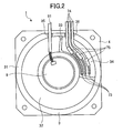
- FIG. 2 is a schematic diagram of the rotating electrical machine 1 without the cover 10 when seen from the opposite-to-load side.
- the bracket 3 includes the communication hole 34, which is connected to the interior space of the housing 2, in a portion of the bottom wall 32.
- the bracket 3 also includes a first opening portion 35 and a second opening portion 36 in the outer wall 31 that serves as the radially outer circumferential surface of the housing 2.
- the first opening portion 35 allows the detector wire 91 to be led out of the bracket 3 therethrough.
- the second opening portion 36 allows the stator wires 73 to be led out of the bracket 3 therethrough.
- the detector wire 91 can be led out of the bracket 3 through the first opening portion 35. Further, the stator wires 73 can be led out of the interior space of the housing 2 to the interior of the bracket 3 through the communication hole 34, and then further led out of the bracket 3 through the second opening portion 36.
- the rotating electrical machine 1 can be easily reduced in size in the axis 0 direction to a greater extent than the available rotating electrical machine in which opening portions for allowing the detector wire 91 and the stator wires 73 to be led to the outside are formed at different positions in the axis 0 direction and on both sides of the bracket 3.
- the communication hole 34 of the bracket 3 forms a space that is separated by the inner wall 33 of the bracket 3 from the space containing the position detector 9.
- the space containing the position detector 9 is a space that is separated from the communication hole 34.
- the communication hole 34 of the bracket 3 has an interior space that can house connectors 75, such as couplers, that connect wires 74 inserted from the outside of the second opening portion 36 to the stator wires 73 inserted from the interior of the housing 2.
- connectors 75 such as couplers
- the wires 74 inserted from the outside of the second opening portion 36 and the stator wires 73 inserted from the interior of the housing 2 are connected to one another in the communication hole 34 of the bracket 3.
- the stator wires 73 can be led out of the bracket 3.
- the communication hole 34 facilitates an operation for connecting the wires 74 and the stator wires 73 in the rotating electrical machine 1.
- the stator wires 73 do not have to be excessively long, handling of the stator 7 is easy when the rotating electrical machine 1 is assembled.
- FIG. 3 is a schematic diagram illustrating the positions at which the first opening portion 35 and the second opening portion 36 are formed.
- a structure is illustrated, for example, in which the stator wires 73 are directly led through the second opening portion 36, instead of a structure in which the stator wires 73 and the wires 74 inserted from the outside of the second opening portion 36 are connected in the bracket 3.
- the first opening portion 35 and the second opening portion 36 are formed in the outer wall 31 of the bracket 3, which serves as the radially outer circumferential surface, so as to be arranged side by side in a direction that is orthogonal to the axis 0 direction of the shaft 6.
- the rotating electrical machine 1 has the first opening portion 35 and the second opening portion 36 that are arranged side by side in the direction that is orthogonal to the axis 0 direction.
- the length of the bracket 3 in the axis 0 direction can be reduced to the minimum.
- the rotating electrical machine 1 can be easily reduced in size in the axis 0 direction.
- first opening portion 35 and the second opening portion 36 are arranged to be close to each other as illustrated in Fig. 3 . This arrangement enables the first opening portion 35 and the second opening portion 36 to be formed concurrently and easily or enables other operations.
- the detector wire 91 is led out of the bracket 3 through the first opening portion 36 formed in the outer wall 31 of the bracket 3.
- the stator wires 73 are led into the interior of the bracket 3 through the communication hole 34 formed in the bracket 3, and then led out of the bracket 3 through the second opening portion 36 that is formed in the outer wall 31 of the bracket 3 such that the second opening portion 36 and the first opening portion 35 are arranged side by side in the direction that is orthogonal to the axis 0 direction.
- first opening portion 35 and the second opening portion 36 are separately formed, one opening portion may be alternatively formed in the outer wall 31 of the bracket 3 in the rotating electrical machine 1 so as to allow the detector wire 91 and the stator wires 73 to be led to the outside therethrough.
- the production process of the bracket 3 can be simplified so that the production cost of the bracket 3 can be further reduced.
- the position detector 9 can be positioned at a position that is closer to the interior space of the housing 2.
- the rotating electrical machine 1 can be easily reduced in size in the axis 0 direction.
- the position detector 9 is contained in the bracket 3 in a space that is located further inward than the stator 7 in the radial direction of the bracket 3.
- the portion of the bottom wall 32 of the bracket 3 that faces the position detector 9 can be made to project inward to the interior space of the housing 2 further beyond the opposite-to-load-side end face of the stator 7.
- the rotating electrical machine 1 can be further reduced in size in the axis 0 direction.
- the position detector 9 may be disposed at a position that is further inward from the housing 2 than the opposite-to-load-side end face of the stator coil 72.
- the rotating electrical machine 1 includes the bracket 3 that is mounted on the opposite-to-load side of the housing 2 and that supports the shaft 6 such that the shaft 6 is rotatable.
- the bracket 3 has the first opening portion 35 and the second opening portion 36 through which the detector wire 91 connected to the position detector 9 and the stator wires 73 connected to the stator 7 are led to the outside.
- the detector wire 91 and the stator wires 73 can be led to the outside through the bracket 3 in the rotating electrical machine 1.
- the rotating electrical machine 1 can be easily reduced in size in the axis 0 direction to a greater extent than the available rotating electrical machine in which opening portions for allowing the detector wire 91 and the stator wires 73 to be lead to the outside are formed at different positions in the axis 0 direction and on both sides of the bracket 3.
- housing 2 and the bracket 3 are formed separately in the embodiment described above, the housing 2 and the bracket 3 may be formed integrally. This structure can reduce the number of components and thus lead to a cost reduction.
- first opening portion 35 and the second opening portion 36 are formed in the outer wall 31 of the bracket 3 so as to be arranged side by side in the direction that is orthogonal to the axis 0 direction.
- the positions at which the first opening portion 35 and the second opening portion 36 are formed are not limited to these.
- the housing 2 has a generally cylindrical shape with a flat portion on the outer circumferential surface.
- the shape of the housing 2 is not limited to this.
- the housing 2 may have a normal cylindrical shape without a flat portion on the outer circumferential surface.
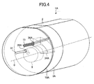
- FIG. 4 is a schematic diagram illustrating the positions at which a first opening portion 35A and a second opening portion 36A according to the first modified example are formed.
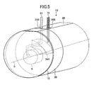
- Fig. 5 is a schematic diagram illustrating the positions at which a first opening portion 35B and a second opening portion 36B according to the second modified example are formed.
- Figs. 4 and 5 the same reference numerals are given to the components that are the same as those in the rotating electrical machine 1 illustrated in Fig. 3 .
- Figs. 4 and 5 each illustrate the case where the stator wires 73 are directly led through the second opening portion 36A or 36B.
- a rotating electrical machine 1A includes a bracket 3A having a communication hole 34A that connects the interior space of the housing 2 and the opposite-to-load side of the bracket 3A.
- the rotating electrical machine 1A also includes a cover 10A that has a first opening portion 35A and a second opening portion 36A and that closes the open opposite-to-load-side end face of the bracket 3A.
- the bracket 3A includes the inner wall 33, as does the bracket 3 illustrated in Fig. 2 .
- the inner wall 33 separates the space housing the position detector 9 from the communication hole 34A.
- the detector wire 91 is led out of the bracket 3A through the first opening portion 35A.
- the stator wires 73 are led from the interior space of the housing 2 to the inside of the bracket 3A, and then led out of the bracket 3A through the second opening portion 36A.
- the rotating electrical machine 1A can be easily reduced in size in the axis 0 direction to a greater extent than the available rotating electrical machine in which opening portions for allowing the detector wire 91 and the stator wires 73 to be led to the outside are formed at different positions in the axis 0 direction and on both sides of the bracket 3A.
- a rotating electrical machine 1B has a first opening portion 35B and a second opening portion 36B in a circumferential surface of a housing 2B.
- a cover 10 illustrated in Fig. 5 corresponds to the cover 10 illustrated in Fig. 3
- a bracket 3B corresponds to the bracket 3A illustrated in Fig. 4 .
- the bracket 3B includes the inner wall 33, as does the bracket 3 illustrated in Fig. 2 .
- the inner wall 33 separates the space housing the position detector 9 from the communication hole 34A.
- the detector wire 91 is led into the interior space of a housing 2B through the communication hole 34A, and then led out of the housing 2B through the first opening portion 35B formed in the outer circumferential surface of the housing 2B.
- the stator wires 73 are led out of the housing 2B from the interior space of the housing 2B through the second opening portion 36B formed in the circumferential surface of the housing 2B.
- the rotating electrical machine 1B can be easily reduced in size in the axis 0 direction to a greater extent than the available rotating electrical machine in which opening portions for allowing the detector wire 91 and the stator wires 73 to be led to the outside are formed at different positions in the axis 0 direction and on both sides of the bracket 3B.
Landscapes
- Engineering & Computer Science (AREA)
- Power Engineering (AREA)
- Microelectronics & Electronic Packaging (AREA)
- Motor Or Generator Frames (AREA)
Abstract
Description
- The present invention relates to rotating electrical machines.
- A rotating electrical machine including a position detector that detects the rotational position of the shaft of the rotating electrical machine has heretofore been available. The position detector is mounted to a shaft that rotates together with a rotor, on a side of the shaft (hereinafter referred to as an "opposite-to-load side") that is opposite to a side on which a load is disposed (hereinafter referred to as a "load side"). In this rotating electrical machine, a bracket that pivotally supports the shaft separates the interior space of the housing that houses a stator from a rotor therein and a space that houses the position detector.
- This rotating electrical machine has an outlet port from which a lead wire connected to the position detector is led out of the rotating electrical machine, and another outlet port from which a lead wire connected to the stator is led out of the rotating electrical machine. These outlet ports are generally formed at different positions in the axial direction of the shaft and on both sides of the bracket (see Japanese Unexamined Patent Application Publication No.
2000-245094 - However, reducing the size of the shaft of the available rotating electrical machine in the axial direction is difficult since multiple outlet ports for allowing the lead wires to be lead out to the outside have to be made at different positions in the axial direction of the shaft on both sides of the bracket.
- Accordingly, it is an object of the present disclosure to provide a rotating electrical machine in which a shaft that rotates together with a rotor can be easily reduced in size in the axial direction.
- A rotating electrical machine disclosed herein includes a cylindrical housing, a position detector, and a bracket. The cylindrical housing houses a stator and a rotor. The position detector is mounted on an opposite-to-load side of a shaft that rotates together with the rotor. The position detector detects a rotational position of the shaft. The bracket is mounted on an opposite-to-load side of the housing. The bracket supports the shaft such that the shaft is rotatable, and has an opening portion through which a wire connected to the position detector and a wire connected to the stator are led to the outside.
- According to an aspect of the rotating electrical machine disclosed herein, it is possible to provide a rotating electrical machine in which a shaft that rotates together with a rotor can be easily reduced in size in the axial direction.
-
-
Fig. 1 is a schematic longitudinal sectional view of a rotating electrical machine according to an embodiment; -
Fig. 2 is a schematic diagram of a rotating electrical machine without a cover, when seen from an opposite-to-load side; -
Fig. 3 is a schematic diagram illustrating the positions at which a first opening portion and a second opening portion are formed; -
Fig. 4 is a schematic diagram illustrating the positions at which a first opening portion and a second opening portion according to a first modified example are formed; and -
Fig. 5 is a schematic diagram illustrating the positions at which a first opening portion and a second opening portion according to a second modified example are formed. - Referring to the attached drawings, embodiments of a rotating electrical machine of the present disclosure will be described in detail below. Note that the embodiments that are exemplarily illustrated below do not restrict the present disclosure.
- Referring to
Fig. 1 first, a structure of a rotatingelectrical machine 1 according to an embodiment will be described.Fig. 1 is a schematic longitudinal sectional view of the rotating electrical machine according to the embodiment. As illustrated inFig. 1 , the rotatingelectrical machine 1 according to the embodiment includes ahousing 2,brackets bearings shaft 6, astator 7, arotor 8, aposition detector 9, and acover 10. - The rotating
electrical machine 1 is interlocked with anexternal device 100 via theshaft 6. Hereinbelow, a case is described where the rotatingelectrical machine 1 functions as a motor and theexternal apparatus 100 functions as a load for the motor. - The
housing 2 is a cylindrical casing and houses thestator 7 and therotor 8 therein. The load-side bracket 4 is mounted on an end portion of a load-side opening of thehousing 2, and the opposite-to-load-side bracket 3 is mounted on an end portion of an opposite-to-load-side opening of thehousing 2. - An outer circumferential portion of the load-
side bracket 4 is attached to the end portion of the load-side opening of thehousing 2, and an inner circumferential portion of the load-side bracket 4 holds thebearing 5B. An outer circumferential portion of the opposite-to-load-side bracket 3 (simply referred to as "bracket 3" below) is attached to the end portion of the opposite-to-load-side opening of thehousing 2, and an inner circumferential portion of thebracket 3 holds thebearing 5A. The structure of thebracket 3 will be described below. - The
shaft 6 is held by thebearings axis 0", below). Thestator 7 includes astator core 71 and astator coil 72, and is fixedly attached to an inner circumferential surface of thehousing 2. Therotor 8 is arranged so as to be opposite the inner circumferential surface of thestator 7 with a gap therebetween. Here, thestator 7 may be molded out of a resin. - The
stator 7 is connected to wires (referred to as "stator wires 73" below) that allow three-phase power for driving theshaft 6 to be provided to thestator 7. The layout of thestator wires 73 will be described below with reference toFig. 2 . - The
rotor 8 includes a cylindrical rotor core and multiple permanent magnets mounted in the rotor core. Therotor 8 rotates about the center of theshaft 6, which is therotational axis 0. For example, the rotor core is formed by stacking multiple thin plates, such as magnetic steel sheets, for reducing eddy currents. The rotor core allows magnetic fluxes of the permanent magnets to pass therethrough. - The
position detector 9 is mounted on the opposite-to-load side of thehousing 2 with thebracket 3 interposed therebetween. Theposition detector 9 is a rotary encoder, a resolver, or the like that detects the rotational position of theshaft 6. Theposition detector 9 is connected to a wire (referred to as a "detector wire 91" below) through which detected results related to the rotational position of theshaft 6 are output to a predetermined controller that is not illustrated (seeFig. 2 ). The layout of thedetector wire 91 will be described below with reference toFig. 2 . Thecover 10 is a closure member that closes an end face of an opposite-to-load-side opening of thebracket 3. - The rotating
electrical machine 1 produces a rotating magnetic field on the inner side of thestator 7 by allowing an electric current to flow through thestator coil 72 of thestator 7. With interaction of a rotating magnetic field and a magnetic field generated by the permanent magnets of therotor 8, therotor 8 rotates and theshaft 6 rotates with the rotation of therotor 8. When, on the other hand, the rotatingelectrical machine 1 is to function as a generator, the operation of the rotatingelectrical machine 1 would be opposite to that in the case of functioning as a motor. That is, when theshaft 6 rotates, therotor 8 rotates with the rotation of theshaft 6, and an electric current is generated in thestator coil 72 of thestator 7. - Hereinbelow, the
bracket 3 will be described further in detail. Thebracket 3 includes anouter wall 31 and abottom wall 32. Theouter wall 31 serves as a circumferential surface of the rotatingelectrical machine 1 when attached to the end portion of the opposite-to-load-side opening of thehousing 2. Thebottom wall 32 faces an interior space of thehousing 2. Thebottom wall 32 has a hole in the center thereof through which theshaft 6 is inserted. The opposite-to-load-side end face of thebracket 3 is open. The open opposite-to-load-side end face is closed with thecover 10. Thebracket 3 also includes aninner wall 33 that is located further inward than theouter wall 31. Thebracket 3 houses theposition detector 9 by use of theinner wall 33, thebottom wall 32, and theouter wall 31. - The
bracket 3 also has acommunication hole 34 in a portion of thebottom wall 32. Thecommunication hole 34 is connected to the interior space of thehousing 2. By allowing thestator wires 73 to be led out of the interior of thehousing 2 to the outside through thecommunication hole 34, the rotatingelectrical machine 1 is easily further reduced in size in theaxis 0 direction. - The
bracket 3 is formed of a nonmagnetic material, a magnetic material, or a combination of a nonmagnetic material and a magnetic material. If thebracket 3 is partially or wholly made of a magnetic material, thebracket 3 has a magnetic shielding function of protecting theposition detector 9. - Referring now to
Fig. 2 , the structure of thebracket 3 that allows thestator wires 73 to be led to the outside through thecommunication hole 34 will be described.Fig. 2 is a schematic diagram of the rotatingelectrical machine 1 without thecover 10 when seen from the opposite-to-load side. - As illustrated in
Fig. 2 , thebracket 3 includes thecommunication hole 34, which is connected to the interior space of thehousing 2, in a portion of thebottom wall 32. Thebracket 3 also includes afirst opening portion 35 and asecond opening portion 36 in theouter wall 31 that serves as the radially outer circumferential surface of thehousing 2. Thefirst opening portion 35 allows thedetector wire 91 to be led out of thebracket 3 therethrough. Thesecond opening portion 36 allows thestator wires 73 to be led out of thebracket 3 therethrough. - Thus, in the rotating
electrical machine 1, thedetector wire 91 can be led out of thebracket 3 through thefirst opening portion 35. Further, thestator wires 73 can be led out of the interior space of thehousing 2 to the interior of thebracket 3 through thecommunication hole 34, and then further led out of thebracket 3 through thesecond opening portion 36. - In this manner, the rotating
electrical machine 1 can be easily reduced in size in theaxis 0 direction to a greater extent than the available rotating electrical machine in which opening portions for allowing thedetector wire 91 and thestator wires 73 to be led to the outside are formed at different positions in theaxis 0 direction and on both sides of thebracket 3. - The
communication hole 34 of thebracket 3 forms a space that is separated by theinner wall 33 of thebracket 3 from the space containing theposition detector 9. In other words, the space containing theposition detector 9 is a space that is separated from thecommunication hole 34. - For this reason, in the rotating
electrical machine 1, impurities such as dust can be kept from entering the space containing theposition detector 9 from the interior space of thehousing 2. Moreover, since the space containing theposition detector 9 is separated from thecommunication hole 34 in the rotatingelectrical machine 1, heat generated in the interior space of thehousing 2 can be kept from entering the space containing theposition detector 9. - The
communication hole 34 of thebracket 3 has an interior space that can houseconnectors 75, such as couplers, that connectwires 74 inserted from the outside of thesecond opening portion 36 to thestator wires 73 inserted from the interior of thehousing 2. - In this manner, the
wires 74 inserted from the outside of thesecond opening portion 36 and thestator wires 73 inserted from the interior of thehousing 2 are connected to one another in thecommunication hole 34 of thebracket 3. Thus, thestator wires 73 can be led out of thebracket 3. - Thus, the
communication hole 34 facilitates an operation for connecting thewires 74 and thestator wires 73 in the rotatingelectrical machine 1. In addition, since thestator wires 73 do not have to be excessively long, handling of thestator 7 is easy when the rotatingelectrical machine 1 is assembled. - Referring now to
Fig. 3 , the positions at which thefirst opening portion 35 and thesecond opening portion 36 are formed will be described.Fig. 3 is a schematic diagram illustrating the positions at which thefirst opening portion 35 and thesecond opening portion 36 are formed. InFig. 3 , a structure is illustrated, for example, in which thestator wires 73 are directly led through thesecond opening portion 36, instead of a structure in which thestator wires 73 and thewires 74 inserted from the outside of thesecond opening portion 36 are connected in thebracket 3. - As illustrated in
Fig. 3 , in the rotatingelectrical machine 1, thefirst opening portion 35 and thesecond opening portion 36 are formed in theouter wall 31 of thebracket 3, which serves as the radially outer circumferential surface, so as to be arranged side by side in a direction that is orthogonal to theaxis 0 direction of theshaft 6. - As described above, the rotating
electrical machine 1 has thefirst opening portion 35 and thesecond opening portion 36 that are arranged side by side in the direction that is orthogonal to theaxis 0 direction. Thus, the length of thebracket 3 in theaxis 0 direction can be reduced to the minimum. Thus, the rotatingelectrical machine 1 can be easily reduced in size in theaxis 0 direction. - Moreover, the
first opening portion 35 and thesecond opening portion 36 are arranged to be close to each other as illustrated inFig. 3 . This arrangement enables thefirst opening portion 35 and thesecond opening portion 36 to be formed concurrently and easily or enables other operations. - In the rotating
electrical machine 1, thedetector wire 91 is led out of thebracket 3 through thefirst opening portion 36 formed in theouter wall 31 of thebracket 3. Thestator wires 73 are led into the interior of thebracket 3 through thecommunication hole 34 formed in thebracket 3, and then led out of thebracket 3 through thesecond opening portion 36 that is formed in theouter wall 31 of thebracket 3 such that thesecond opening portion 36 and thefirst opening portion 35 are arranged side by side in the direction that is orthogonal to theaxis 0 direction. - Although the
first opening portion 35 and thesecond opening portion 36 are separately formed, one opening portion may be alternatively formed in theouter wall 31 of thebracket 3 in the rotatingelectrical machine 1 so as to allow thedetector wire 91 and thestator wires 73 to be led to the outside therethrough. - Since the shape of the
bracket 3 can be simplified with this structure, the production process of thebracket 3 can be simplified so that the production cost of thebracket 3 can be further reduced. - In the
bracket 3 of the rotatingelectrical machine 1, a portion of thebottom wall 32 that faces theposition detector 9 projects further into the interior space of thehousing 2 than the other portion of thebottom wall 32 that does not face the position detector 9 (seeFig. 1 ). Thus, theposition detector 9 can be positioned at a position that is closer to the interior space of thehousing 2. - Thus, the rotating
electrical machine 1 can be easily reduced in size in theaxis 0 direction. Theposition detector 9 is contained in thebracket 3 in a space that is located further inward than thestator 7 in the radial direction of thebracket 3. - In this manner, in the rotating
electrical machine 1, the portion of thebottom wall 32 of thebracket 3 that faces theposition detector 9 can be made to project inward to the interior space of thehousing 2 further beyond the opposite-to-load-side end face of thestator 7. Thus, the rotatingelectrical machine 1 can be further reduced in size in theaxis 0 direction. In this case, theposition detector 9 may be disposed at a position that is further inward from thehousing 2 than the opposite-to-load-side end face of thestator coil 72. - As described above, the rotating
electrical machine 1 according to the embodiment includes thebracket 3 that is mounted on the opposite-to-load side of thehousing 2 and that supports theshaft 6 such that theshaft 6 is rotatable. Thebracket 3 has thefirst opening portion 35 and thesecond opening portion 36 through which thedetector wire 91 connected to theposition detector 9 and thestator wires 73 connected to thestator 7 are led to the outside. - Thus, the
detector wire 91 and thestator wires 73 can be led to the outside through thebracket 3 in the rotatingelectrical machine 1. In this manner, the rotatingelectrical machine 1 can be easily reduced in size in theaxis 0 direction to a greater extent than the available rotating electrical machine in which opening portions for allowing thedetector wire 91 and thestator wires 73 to be lead to the outside are formed at different positions in theaxis 0 direction and on both sides of thebracket 3. - Although the
housing 2 and thebracket 3 are formed separately in the embodiment described above, thehousing 2 and thebracket 3 may be formed integrally. This structure can reduce the number of components and thus lead to a cost reduction. - In the embodiment described above, a case is described where the
first opening portion 35 and thesecond opening portion 36 are formed in theouter wall 31 of thebracket 3 so as to be arranged side by side in the direction that is orthogonal to theaxis 0 direction. However, the positions at which thefirst opening portion 35 and thesecond opening portion 36 are formed are not limited to these. - In the example illustrated in
Fig. 3 , thehousing 2 has a generally cylindrical shape with a flat portion on the outer circumferential surface. However, the shape of thehousing 2 is not limited to this. For example, thehousing 2 may have a normal cylindrical shape without a flat portion on the outer circumferential surface. - Referring now to
Figs. 4 and5 , a description will be given of a first modified example and a second modified example in which the positions at which thefirst opening portion 35 and thesecond opening portion 36 are modified.Fig. 4 is a schematic diagram illustrating the positions at which afirst opening portion 35A and asecond opening portion 36A according to the first modified example are formed.Fig. 5 is a schematic diagram illustrating the positions at which afirst opening portion 35B and asecond opening portion 36B according to the second modified example are formed. - In
Figs. 4 and5 , the same reference numerals are given to the components that are the same as those in the rotatingelectrical machine 1 illustrated inFig. 3 . LikeFig. 3 ,Figs. 4 and5 each illustrate the case where thestator wires 73 are directly led through thesecond opening portion - As illustrated in
Fig. 4 , a rotatingelectrical machine 1A according to the first modified example includes abracket 3A having acommunication hole 34A that connects the interior space of thehousing 2 and the opposite-to-load side of thebracket 3A. The rotatingelectrical machine 1A also includes acover 10A that has afirst opening portion 35A and asecond opening portion 36A and that closes the open opposite-to-load-side end face of thebracket 3A. - Although not illustrated herein, the
bracket 3A includes theinner wall 33, as does thebracket 3 illustrated inFig. 2 . Theinner wall 33 separates the space housing theposition detector 9 from thecommunication hole 34A. - In the rotating
electrical machine 1A, thedetector wire 91 is led out of thebracket 3A through thefirst opening portion 35A. Thestator wires 73 are led from the interior space of thehousing 2 to the inside of thebracket 3A, and then led out of thebracket 3A through thesecond opening portion 36A. - Also with this structure, the rotating
electrical machine 1A can be easily reduced in size in theaxis 0 direction to a greater extent than the available rotating electrical machine in which opening portions for allowing thedetector wire 91 and thestator wires 73 to be led to the outside are formed at different positions in theaxis 0 direction and on both sides of thebracket 3A. - As illustrated in
Fig. 5 , a rotatingelectrical machine 1B according to the second modified example has afirst opening portion 35B and asecond opening portion 36B in a circumferential surface of ahousing 2B. Here, acover 10 illustrated inFig. 5 corresponds to thecover 10 illustrated inFig. 3 , and abracket 3B corresponds to thebracket 3A illustrated inFig. 4 . - Although not illustrated herein, the
bracket 3B includes theinner wall 33, as does thebracket 3 illustrated inFig. 2 . Theinner wall 33 separates the space housing theposition detector 9 from thecommunication hole 34A. - In the rotating
electrical machine 1B, thedetector wire 91 is led into the interior space of ahousing 2B through thecommunication hole 34A, and then led out of thehousing 2B through thefirst opening portion 35B formed in the outer circumferential surface of thehousing 2B. Thestator wires 73 are led out of thehousing 2B from the interior space of thehousing 2B through thesecond opening portion 36B formed in the circumferential surface of thehousing 2B. - Also with this structure, the rotating
electrical machine 1B can be easily reduced in size in theaxis 0 direction to a greater extent than the available rotating electrical machine in which opening portions for allowing thedetector wire 91 and thestator wires 73 to be led to the outside are formed at different positions in theaxis 0 direction and on both sides of thebracket 3B. - Those skilled in the art can easily conceive of further effects or modifications. Thus, broader aspects of the present disclosure should not be limited to the specific details and the typical embodiments that are described as above in detail. Accordingly, the present disclosure can be modified in various ways without departing from the spirit or the scope of the general gist of the disclosure that is specified by the scope of claims and equivalents thereof.
Claims (7)
- A rotating electrical machine (1, 1A, 1B) characterized by comprising:a cylindrical housing (2, 2B) that houses a stator (7) and a rotor (8);a position detector (9) that is mounted on an opposite-to-load side of a shaft (6) that rotates together with the rotor (8), the position detector (9) being configured to detect a rotational position of the shaft (6); anda bracket (3, 3A, 3B) that is mounted on an opposite-to-load side of the housing (2, 2B), the bracket (3, 3A, 3B) being configured to support the shaft (6) such that the shaft (6) is rotatable and the bracket (3, 3A, 3B) having an opening portion through which a wire (91) connected to the position detector (9) and a wire (73) connected to the stator (7) are led to the outside.
- The rotating electrical machine according to Claim 1, characterized in that
the opening portion includes a first opening portion through which the wire connected to the position detector is led to the outside, and a second opening portion through which the wire connected to the stator is led to the outside, and
the first opening portion and the second opening portion are formed in a radially outer circumferential surface of the bracket so as to be arranged side by side in a direction that is orthogonal to an axial direction of the shaft. - The rotating electrical machine according to Claim 2, characterized in that the bracket has a separate space that is connected to an interior of the housing and the second opening portion and that is separated from the position detector.
- The rotating electrical machine according to Claim 3, characterized in that the separate space houses a connector that connects a wire that is inserted from the outside of the second opening portion and the wire that is connected to the stator and inserted from the interior of the housing.
- The rotating electrical machine according to any one of Claims 1 to 4, characterized in that the position detector is housed in the bracket at a position that is closer to the housing than an end face of the bracket on an opposite-to-load side is.
- The rotating electrical machine according to any one of Claims 1 to 5, characterized in that the position detector is housed in the bracket in a space that is located further inward than the stator in a radial direction of the bracket.
- The rotating electrical machine according to any one of Claims 1 to 6, characterized in that the bracket and the housing are formed integrally.
Applications Claiming Priority (1)
| Application Number | Priority Date | Filing Date | Title |
|---|---|---|---|
| JP2011058552A JP5360099B2 (en) | 2011-03-16 | 2011-03-16 | Rotating electric machine |
Publications (2)
| Publication Number | Publication Date |
|---|---|
| EP2501021A2 true EP2501021A2 (en) | 2012-09-19 |
| EP2501021A3 EP2501021A3 (en) | 2016-08-03 |
Family
ID=45531809
Family Applications (1)
| Application Number | Title | Priority Date | Filing Date |
|---|---|---|---|
| EP12153454.9A Withdrawn EP2501021A3 (en) | 2011-03-16 | 2012-02-01 | Rotating electrical machine |
Country Status (3)
| Country | Link |
|---|---|
| EP (1) | EP2501021A3 (en) |
| JP (1) | JP5360099B2 (en) |
| CN (1) | CN102684352B (en) |
Families Citing this family (1)
| Publication number | Priority date | Publication date | Assignee | Title |
|---|---|---|---|---|
| KR102026564B1 (en) * | 2018-05-11 | 2019-11-04 | (주)타마스 | Hollow Shaft Motor with Improved Housing Structure |
Family Cites Families (14)
| Publication number | Priority date | Publication date | Assignee | Title |
|---|---|---|---|---|
| JP3816353B2 (en) * | 2001-05-25 | 2006-08-30 | 三菱電機株式会社 | Electric power steering motor |
| JP2004040853A (en) * | 2002-06-28 | 2004-02-05 | Mitsuba Corp | Electric power steering device |
| DE10302130A1 (en) * | 2003-01-21 | 2004-08-05 | Minebea Co., Ltd. | Motor housing for an electric motor |
| DE10312869A1 (en) * | 2003-03-19 | 2004-10-07 | Minebea Co., Ltd. | electric motor |
| JP4613544B2 (en) * | 2004-07-30 | 2011-01-19 | トヨタ自動車株式会社 | Resolver stator fixing structure |
| JP3881351B2 (en) * | 2004-08-06 | 2007-02-14 | 三菱電機株式会社 | Electric power steering motor |
| JP4956923B2 (en) * | 2005-06-23 | 2012-06-20 | 日本電産株式会社 | Brushless motor |
| JP4821303B2 (en) * | 2005-12-15 | 2011-11-24 | 日本精工株式会社 | Brushless motor and electric power steering apparatus using the same |
| JP5088655B2 (en) * | 2006-01-06 | 2012-12-05 | 日本精工株式会社 | Motor and motor manufacturing method |
| US20070159017A1 (en) * | 2006-01-11 | 2007-07-12 | Martin Jerry L | Explosion-proof motor with integrated sensor/lead housing |
| JP2007195344A (en) * | 2006-01-19 | 2007-08-02 | Jtekt Corp | motor |
| JP2009232602A (en) * | 2008-03-24 | 2009-10-08 | Mitsuba Corp | Electric motor and method of manufacturing that electric motor |
| FR2935564A1 (en) * | 2008-09-03 | 2010-03-05 | Michelin Soc Tech | DEVICE FOR MOUNTING A RESOLVER IN AN ELECTRIC MACHINE |
| JP2010172086A (en) * | 2009-01-21 | 2010-08-05 | Nippon Densan Corp | Busbar unit, method of manufacturing busbar unit, and motor |
-
2011
- 2011-03-16 JP JP2011058552A patent/JP5360099B2/en active Active
-
2012
- 2012-02-01 EP EP12153454.9A patent/EP2501021A3/en not_active Withdrawn
- 2012-02-28 CN CN201210048570.9A patent/CN102684352B/en not_active Expired - Fee Related
Also Published As
| Publication number | Publication date |
|---|---|
| EP2501021A3 (en) | 2016-08-03 |
| JP2012196060A (en) | 2012-10-11 |
| CN102684352B (en) | 2014-07-30 |
| CN102684352A (en) | 2012-09-19 |
| JP5360099B2 (en) | 2013-12-04 |
Similar Documents
| Publication | Publication Date | Title |
|---|---|---|
| CN106849449B (en) | motor | |
| JP5594275B2 (en) | Rotating electric machine | |
| JP6175708B2 (en) | motor | |
| KR101555804B1 (en) | Rotary electric machine | |
| JP6847021B2 (en) | Brushless motor | |
| JP7275432B2 (en) | motor | |
| CN107078598A (en) | drive unit | |
| EP2083506A1 (en) | Motor-operated fan apparatus | |
| EP3474425B1 (en) | Motor device | |
| CN103795166A (en) | Rotor and rotating electric machine having the same | |
| JP6559370B1 (en) | Encoder and servo motor | |
| CN209608462U (en) | motor | |
| CN105393440B (en) | Motor | |
| CN110959248A (en) | Motor with a stator having a stator core | |
| JP5459246B2 (en) | Resolver | |
| CN102684352B (en) | Rotating electrical machine | |
| US11005333B2 (en) | Electric motor having a stator with a radially outside rotor with the rotor having a fan mounting portion comprising a noncontact region and a contract region configured to contact a mouting surface of a fan | |
| JP2012247350A (en) | Rotary electric machine | |
| JP2012249461A (en) | Electric motor | |
| EP3996253A1 (en) | Motor, electric tool motor, and electric tool | |
| CN103683554A (en) | Motor stator set | |
| JP6578979B2 (en) | Brushless motor | |
| KR20130041186A (en) | Electric machine alignment adapter | |
| JP2017077037A5 (en) | ||
| JP2019170115A (en) | Resolver |
Legal Events
| Date | Code | Title | Description |
|---|---|---|---|
| PUAI | Public reference made under article 153(3) epc to a published international application that has entered the european phase |
Free format text: ORIGINAL CODE: 0009012 |
|
| AK | Designated contracting states |
Kind code of ref document: A2 Designated state(s): AL AT BE BG CH CY CZ DE DK EE ES FI FR GB GR HR HU IE IS IT LI LT LU LV MC MK MT NL NO PL PT RO RS SE SI SK SM TR |
|
| AX | Request for extension of the european patent |
Extension state: BA ME |
|
| PUAL | Search report despatched |
Free format text: ORIGINAL CODE: 0009013 |
|
| RIC1 | Information provided on ipc code assigned before grant |
Ipc: H02K 5/22 20060101ALI20160622BHEP Ipc: H02K 11/00 20160101AFI20160622BHEP |
|
| AK | Designated contracting states |
Kind code of ref document: A3 Designated state(s): AL AT BE BG CH CY CZ DE DK EE ES FI FR GB GR HR HU IE IS IT LI LT LU LV MC MK MT NL NO PL PT RO RS SE SI SK SM TR |
|
| AX | Request for extension of the european patent |
Extension state: BA ME |
|
| STAA | Information on the status of an ep patent application or granted ep patent |
Free format text: STATUS: THE APPLICATION HAS BEEN WITHDRAWN |
|
| 18W | Application withdrawn |
Effective date: 20160725 |