EP2500766A1 - Method for continuously manufacturing liquid crystal display panel and inspection method - Google Patents

Method for continuously manufacturing liquid crystal display panel and inspection method Download PDF

Info

Publication number
EP2500766A1
EP2500766A1 EP11185696A EP11185696A EP2500766A1 EP 2500766 A1 EP2500766 A1 EP 2500766A1 EP 11185696 A EP11185696 A EP 11185696A EP 11185696 A EP11185696 A EP 11185696A EP 2500766 A1 EP2500766 A1 EP 2500766A1
Authority
EP
European Patent Office
Prior art keywords
liquid crystal
crystal display
display panel
line
feeder
Prior art date
Legal status (The legal status is an assumption and is not a legal conclusion. Google has not performed a legal analysis and makes no representation as to the accuracy of the status listed.)
Withdrawn
Application number
EP11185696A
Other languages
German (de)
French (fr)
Inventor
Satoshi Hirata
Takuya Nakazono
Tomokazu Yura
Current Assignee (The listed assignees may be inaccurate. Google has not performed a legal analysis and makes no representation or warranty as to the accuracy of the list.)
Nitto Denko Corp
Original Assignee
Nitto Denko Corp
Priority date (The priority date is an assumption and is not a legal conclusion. Google has not performed a legal analysis and makes no representation as to the accuracy of the date listed.)
Filing date
Publication date
Application filed by Nitto Denko Corp filed Critical Nitto Denko Corp
Publication of EP2500766A1 publication Critical patent/EP2500766A1/en
Withdrawn legal-status Critical Current

Links

Images

Classifications

    • GPHYSICS
    • G02OPTICS
    • G02FOPTICAL DEVICES OR ARRANGEMENTS FOR THE CONTROL OF LIGHT BY MODIFICATION OF THE OPTICAL PROPERTIES OF THE MEDIA OF THE ELEMENTS INVOLVED THEREIN; NON-LINEAR OPTICS; FREQUENCY-CHANGING OF LIGHT; OPTICAL LOGIC ELEMENTS; OPTICAL ANALOGUE/DIGITAL CONVERTERS
    • G02F1/00Devices or arrangements for the control of the intensity, colour, phase, polarisation or direction of light arriving from an independent light source, e.g. switching, gating or modulating; Non-linear optics
    • G02F1/01Devices or arrangements for the control of the intensity, colour, phase, polarisation or direction of light arriving from an independent light source, e.g. switching, gating or modulating; Non-linear optics for the control of the intensity, phase, polarisation or colour 
    • G02F1/13Devices or arrangements for the control of the intensity, colour, phase, polarisation or direction of light arriving from an independent light source, e.g. switching, gating or modulating; Non-linear optics for the control of the intensity, phase, polarisation or colour  based on liquid crystals, e.g. single liquid crystal display cells
    • G02F1/1306Details
    • G02F1/1309Repairing; Testing
    • GPHYSICS
    • G01MEASURING; TESTING
    • G01NINVESTIGATING OR ANALYSING MATERIALS BY DETERMINING THEIR CHEMICAL OR PHYSICAL PROPERTIES
    • G01N21/00Investigating or analysing materials by the use of optical means, i.e. using sub-millimetre waves, infrared, visible or ultraviolet light
    • G01N21/84Systems specially adapted for particular applications
    • G01N21/88Investigating the presence of flaws or contamination
    • GPHYSICS
    • G02OPTICS
    • G02FOPTICAL DEVICES OR ARRANGEMENTS FOR THE CONTROL OF LIGHT BY MODIFICATION OF THE OPTICAL PROPERTIES OF THE MEDIA OF THE ELEMENTS INVOLVED THEREIN; NON-LINEAR OPTICS; FREQUENCY-CHANGING OF LIGHT; OPTICAL LOGIC ELEMENTS; OPTICAL ANALOGUE/DIGITAL CONVERTERS
    • G02F1/00Devices or arrangements for the control of the intensity, colour, phase, polarisation or direction of light arriving from an independent light source, e.g. switching, gating or modulating; Non-linear optics
    • G02F1/01Devices or arrangements for the control of the intensity, colour, phase, polarisation or direction of light arriving from an independent light source, e.g. switching, gating or modulating; Non-linear optics for the control of the intensity, phase, polarisation or colour 
    • G02F1/13Devices or arrangements for the control of the intensity, colour, phase, polarisation or direction of light arriving from an independent light source, e.g. switching, gating or modulating; Non-linear optics for the control of the intensity, phase, polarisation or colour  based on liquid crystals, e.g. single liquid crystal display cells
    • G02F1/133Constructional arrangements; Operation of liquid crystal cells; Circuit arrangements
    • G02F1/1333Constructional arrangements; Manufacturing methods
    • G02F1/1335Structural association of cells with optical devices, e.g. polarisers or reflectors

Definitions

  • the invention relates to a system and a method for continuously manufacturing a liquid crystal display panel and to an inspection apparatus and an inspection method.
  • JP-A No. 2010-170126 discloses a method and a system for manufacturing a liquid crystal display panel by a process including the steps of laminating polarizing films on both the front and back surfaces of a liquid crystal cell to form a liquid crystal display panel and optically inspecting the liquid crystal display panel.
  • the disclosed inspecting step includes perpendicularly applying light to the lower surface of the liquid crystal display panel from a light source, imaging the transmitted light to obtain image data, and subjecting the obtained image data to image analysis to determine the presence or absence of a defect so that it can be determined whether the product is non-defective or defective.
  • JP-A Japanese Patent Application Laid-Open
  • 2010-170126 has a problem in which foreign bodies contained in a liquid crystal display panel cannot be easily detected.
  • the reason is as follows. If a foreign body exists between a liquid crystal cell and a polarizing plate, only part of the polarizing plate where the foreign body exits should be deformed and undergo the cancellation of the crossed Nicols state so that only the part should form a white image due to light leakage.
  • a light source and a camera are placed opposite to each other, as shown in Figs. 7A and 7B , not only the light generated by the cancellation of the crossed Nicols state but also light refracted, scattered, or reflected by the foreign body enter the camera.
  • the noise increases around the foreign body (the contrast decreases) so that the outline of the foreign body is blurred, which causes a problem in which the foreign body cannot be easily detected (the inspection precision decreases).
  • the invention has been made under the above circumstances, and an object of the invention is to provide a system and a method for continuously manufacturing a liquid crystal display panel, and an inspection apparatus and an inspection method, which enable high precision inspection of liquid crystal display panels being fed at high speed so that liquid crystal display panels of high quality can be continuously manufactured at high speed.
  • the Invention is directed to a system for continuously manufacturing a liquid crystal display panel, includes:
  • the line-shaped light beam is applied to the liquid crystal display panel being fed, and scattered light passing through the liquid crystal display panel is continuously imaged in a line pattern, so that foreign bodies existing between a liquid crystal cell and a polarizing plate are successfully imaged with sharp contrast over the whole of the liquid crystal display panel being fed at high speed (the noise around the foreign bodies is reduced, because light scattered by the foreign bodies can be selectively images)
  • high precision inspection is successfully performed while liquid crystal display panels are fed at high speed, so that liquid crystal display panels of high quality can be continuously manufactured at high speed.
  • This inspection makes it possible to perform high-precision detection of not only foreign bodies existing between a liquid crystal cell and a polarizing plate (such as bonding air bubbles, cullet, lint, dust, and dirt) but also stains and the like.
  • the image pickup unit is disposed in each of positions tilted at a predetermined angle to the feed direction of the feeder and the direction opposite thereto with respect to the direction in which the line-shaped light beam is applied from the light application unit.
  • the image pickup unit is also preferably disposed in each of positions that are tilted to the feed direction of the feeder and the direction opposite thereto and symmetrical with respect to the direction in which the line-shaped light beam is applied from the light application unit.
  • the Invention is directed to a method for continuously manufacturing a liquid crystal display panel, includes:
  • the line-shaped light beam is applied to the liquid crystal display panel being fed, and scattered light passing through the liquid crystal display panel is continuously imaged in a line pattern, so that foreign bodies existing between a liquid crystal cell and a polarizing plate are successfully image with sharp contrast over the whole of the liquid crystal display panel being fed at high speed (the noise around the foreign bodies is reduced, because light scattered by the foreign bodies can be selectively image).
  • high precision inspection is successfully performed while liquid crystal display panels are fed at high speed, so that liquid crystal display panels of high quality can be continuously manufactured at high speed.
  • the image pickup unit is disposed in each of positions tilted at a predetermined angle to the feed direction of the feeder and the direction opposite thereto with respect to the direction in which the line-shaped light beam is applied from the light application unit.
  • the region irradiated with the line-shaped light beam in the liquid crystal display panel is also preferably imaged in a line pattern at positions symmetrically tilted to the feed direction of the liquid crystal display panel and the direction opposite thereto with respect to the direction in which the line-shaped light beam is applied.
  • the imaging is also preferably performed in such a manner that the region irradiated with the line-shaped light beam in the liquid crystal display panel is imaged in a line pattern at a position or positions tilted at an angle of 1° to 45° with respect to the direction in which the line-shaped light beam is applied.
  • the Invention is directed to a inspection apparatus for optically inspecting a liquid crystal display panel being fed by a feeder, includes:
  • the line-shaped light beam is applied to the liquid crystal display panel being fed, and scattered light passing through the liquid crystal display panel is continuously imaged in a line pattern, so that foreign bodies existing between a liquid crystal cell and a polarizing plate are successfully with sharp contrast over the whole of the liquid crystal display panel being fed at high speed (the noise around the foreign bodies is reduced, because light scattered by the foreign bodies can be selectively imaged).
  • high precision inspection is successfully performed while liquid crystal display panels are fed at high speed.
  • the light application unit applies the line-shaped light beam in a direction perpendicular to the liquid crystal display panel. According to this feature, even when the liquid crystal display panel is misaligned during the feeding (for example, when the direction of the long or short side of the liquid crystal display panel becomes non-parallel to the feed direction of the feed line which is formed by the feeder), light leakage (noise) caused by such misalignment can be reduced so that high inspection precision can be maintained.
  • the image pickup unit is also preferably disposed in each of positions that are tilted to the feed direction of the feeder and the direction opposite thereto and symmetrical with respect to the direction in which the line-shaped light beam is applied from the light application unit.
  • the image pickup unit is also preferably disposed to be tilted at an angle of 1° to 45° with respect to the direction in which the line-shaped light beam is applied from the light application unit.
  • the invention is directed to a method for optically inspecting a liquid crystal display panel being fed by a feeder, includes:
  • the line-shaped light beam is applied to the liquid crystal display panel being fed, and scattered light passing through the liquid crystal display panel is continuously imaged in a line pattern, so that foreign bodies existing between a liquid crystal cell and a polarizing plate are successfully imaged with sharp contrast over the whole of the liquid crystal display panel being fed at high speed (the noise around the foreign bodies is reduced, because light scattered by the foreign bodies can be selectively imaged).
  • high precision inspection is successfully performed while liquid crystal display panels are fed at high speed.
  • the light application unit applies the line-shaped light beam in a direction perpendicular to the liquid crystal display panel. According to this feature, even when the liquid crystal display panel is misaligned during the feeding (for example, when the direction of the long or short side of the liquid crystal display panel becomes non-parallel to the feed direction of the feed line which is formed by the feeder), light leakage (noise) caused by such misalignment can be reduced so that high inspection precision can be maintained.
  • the image pickup unit is disposed in each of positions tilted at a predetermined angle to the feed direction of the feeder and the direction opposite thereto with respect to the direction in which the line-shaped light beam is applied from the light application unit.
  • the region irradiated with the line-shaped light beam in the liquid crystal display panel is also preferably imaged in a line pattern at positions symmetrically tilted to the feed direction of the liquid crystal display panel and the direction opposite thereto with respect to the direction in which the line-shaped light beam is applied.
  • the imaging is also preferably such that the region irradiated with the line-shaped light beam in the liquid crystal display panel is imaged in a line pattern at a position or positions tilted at an angle of 1° to 45° with respect to the direction in which the line-shaped light beam is applied.
  • a system for continuously manufacturing a liquid crystal display panel is that a system is arranged a manufacturing apparatus 100 and a inspection apparatus 300, respectively on a continuous feeder 400 for feeding the liquid crystal cell 4 and the liquid crystal display panel Y.
  • the manufacturing apparatus 100 manufactures a liquid crystal display panel Y by a process including cutting a first long polarizing plate 11 and a second long polarizing plate 21, respectively, to form a first polarizing plate 13 and a second polarizing plate 23, while feeding the first long polarizing plate 11 and the second long polarizing plate 21 from a first polarizing plate roll 1 and a second polarizing plate roll 2, respectively, and bonding the first polarizing plate 13 and the second polarizing plate 23 to both sides of a liquid crystal cell 4, which is being fed, in such a manner that their absorption axes are perpendicular to each other.
  • the feeder 400 includes image pickup units (312, 314) that are placed on the other side with respect to the feeder 400 and disposed in positions tilted at a predetermined angle to the feed direction d1 of the feeder 400 and the direction opposite thereto, respectively, with respect to the direction P in which the line-shaped light beam L is applied from the light application unit 311, wherein the image pickup units are for continuously imaging the region irradiated with the line-shaped light beam L in the liquid crystal display panel Y being fed by the feeder 400, and the imaging is performed in a line pattern parallel to the width direction d2 of the feeder 400.
  • the polarizing plate roll which is formed by winding a long polarizing plate, may be (1) a roll of an optical film laminate that is in the form of a continuous web and includes a carrier film and a pressure-sensitive adhesive-containing long polarizing plate formed on the carrier film.
  • the system for continuously manufacturing a liquid crystal display panel further includes a cutting apparatus for forming pieces of the polarizing plate (sheet pieces) from the long polarizing plate by cutting (half-cutting or forming score lines in) the long polarizing plate (including the pressure-sensitive adhesive) at predetermined intervals in a direction perpendicular to the feed direction of the carrier film, while the carrier film is left uncut.
  • the polarizing plate roll may be (2) a roll of an optical film laminate including a carrier film and pieces of the polarizing plate (including the pressure-sensitive adhesive), which are formed on the carrier film and placed adjacent to one another with a score line interposed between the adjacent pieces (a roll of a so-called scored polarizing plate).
  • the polarizing plate roll 1 shown in Fig. 1 is a roll of a first optical film laminate 10 including a first carrier film 12 and a long polarizing plate 11 (including a pressure-sensitive adhesive) that has an absorption axis parallel to the feed direction (longitudinal direction) and is formed on the first carrier film 12 with the pressure-sensitive adhesive interposed therebetween.
  • the polarizing plate roll 2 is a roll of a second optical film laminate 20 including a second carrier film 22 and a long polarizing plate 21 (including a pressure-sensitive adhesive) that has an absorption axis parallel to the feed direction (longitudinal direction) and is formed on the second carrier film 22 with the pressure-sensitive adhesive interposed therebetween.
  • the polarizing plate includes a polarizer (about 5 to about 80 ⁇ m in thickness) and a polarizer protecting film or films (generally about 1 to about 500 ⁇ m in thickness) farmed on one or both sides of the polarizer with or without an adhesive.
  • the optical film laminate 10 may further include any other film component such as a retardation film (generally 10 to 200 ⁇ m in thickness), a viewing angle compensation film, a brightness enhancement film, or a surface protecting film.
  • the thickness of the optical film laminate is typically in the range of 10 ⁇ m to 500 ⁇ m.
  • the pressure-sensitive adhesive interposed between the first or second carrier film 12 or 22 and the polarizing plate is typically, but not limited to, an acryl-based pressure-sensitive adhesive, a silicone pressure-sensitive adhesive, a urethane pressure-sensitive adhesive, or the like.
  • the thickness of the pressure-sensitive adhesive layer is preferably in the range of 10 to 50 ⁇ m.
  • the first and second carrier films 12 and 22 to be used may each be such a known conventional film as a plastic film (e.g., a polyethylene terephthalate film or a polyolefin film).
  • any appropriate film such as a film coated with an appropriate release agent such as a silicone, long-chain alkyl or fluoride release agent, or molybdenum sulfide may also be used as needed.
  • the manufacturing apparatus 100 includes a first carrier film feeder 101, a first bonding unit 102, a second carrier film feeder 103, and a second bonding unit 104.
  • the first carrier film feeder 101 While feeding the first long polarizing plate 11 (first optical film laminate 10) from the first polarizing plate roll 1, the first carrier film feeder 101 cuts the first polarizing plate 11 (including the pressure-sensitive adhesive) to form a first polarizing plate 111, peels off the first polarizing plate 111 (including the pressure-sensitive adhesive) from the first carrier film 12, and supplies the first polarizing plate 111 to the first bonding unit 102.
  • the first carrier film feeder 101 includes a first cutting unit 35, a first dancer roller 30, a first peeling unit 40, and a first take-up unit 60.
  • the first dancer roller 30 has the function of maintaining tension on the first carrier film 12.
  • the first peeling unit 40 inwardly folds back the first carrier film 12 at its front end to peel off the first polarizing plate 111 from the first carrier film 12.
  • a sharp knife edge is used as a non-limiting example of the front end of the first peeling unit 40.
  • the first take-up unit 60 takes up the first carrier film 12 from which the first polarizing plate 111 is peeled off.
  • the first bonding unit 102 bonds the first polarizing plate 111 from the upper side to the liquid crystal cell 4, which is fed by the feeder 400, with the pressure-sensitive adhesive interposed therebetween, when the first polarizing plate 111 is peeled off from the first carrier film 12 by the first peeling unit 40.
  • the first bonding unit 102 includes a first bonding roller 50a and a first drive roller 50b.
  • each unit or apparatus as described above may be used as each apparatus for bonding the second polarizing plate 211 to the other side of the liquid crystal cell 4.
  • the second carrier film feeder 103 may have the same device configuration as the first carrier film feeder 101
  • the second bonding unit 104 may have the same device configuration as the first bonding unit 102.
  • a second dancer roller 30 may have the same device configuration as the first dancer roller 30
  • a second take-up unit 60 may have the same device configuration as the first take-up unit 60
  • a second bonding roller 50a and a second drive roller 50b may have the same mechanism as the first bonding roller 50a and the first drive roller 50b.
  • the inspection apparatus 300 includes: a light application unit 311 which is placed on one side (the lower side) with respect to the feeder 400 in Fig. 1 so as to apply a line-shaped light beam L to the liquid crystal display panel Y being fed by the feeder 400, wherein the light beam L is parallel to the width direction d2 of the feeder 400; and image pickup units (a first image pickup unit 312 and a second image pickup unit 314) that are placed on the other side (upper side) with respect to the feeder 400 in Fig.
  • the image pickup units are for continuously imaging the region irradiated with the line-shaped light beam L in the liquid crystal display panel Y being fed by the feeder 400, and the imaging is performed in a line pattern parallel to the width direction d2 of the feeder 400.
  • the light application unit 311 may be placed on the upper side with respect to the feeder 400, and the image pickup units may be placed on the lower side with respect to the feeder 400, depending on the state of the liquid crystal display panel Y to be inspected.
  • the light application unit 311 applies a line-shaped light beam L perpendicularly to the surface of the liquid crystal display panel Y.
  • the light application unit 311 may be any unit capable of applying a line-shaped light beam L traveling in a straight line, examples of which include a halogen lamp, a metal halide lamp, and an LED line light.
  • the line-shaped light beam L extends in a line shape in the width direction d2 of the feeder 400, and the transverse width of the line-shaped light beam L (in a direction parallel to the feed direction d1 of the feeder 400) is shorter than the feed-direction length of the liquid crystal display panel.
  • the light application unit 311 may further include a lens part for reducing the transverse width of the line-shaped light beam L.
  • the lens part may include a cylindrical rod lens formed along the longitudinal direction of the line-shaped light beam.
  • the line-shaped light beam is preferably concentrated in such a manner that its transverse width can be reduced, because such concentration makes it possible to apply high-intensity light to the surface of the liquid crystal display panel and to reduce the arithmetic processing time (or to increase the processing speed) by using small-area image data to keep the data processing capacity small, so that high inspection precision can be obtained.
  • the distance between the light application unit 311 and the feeder 400 may be appropriately controlled depending on the type or size of the liquid crystal display panel, the feed speed, or the like.
  • the image pickup units include a first image pickup unit 312 and a second image pickup unit 314.
  • the first image pickup unit 312 is placed in a position tilted at a predetermined angle ( ⁇ 1) to a direction opposite to the feed direction d1 of the liquid crystal display panel Y with respect to the direction P in which the line-shaped light beam L is applied from the light application unit 311.
  • the second image pickup unit 314 is placed in a position tilted at a predetermined angle ( ⁇ 2) to the feed direction d1 of the liquid crystal display panel Y with respect to the direction P in which the line-shaped light beam L is applied from the light application unit 311.
  • the predetermined angle ( ⁇ 1, ⁇ 2) and the distance between the first or second image pickup unit 312 or 314 and the feeder 400 are appropriately determined depending on the type or size of the liquid crystal display panel, the feed speed, or the like.
  • the predetermined angle ( ⁇ 1, ⁇ 2) may be in the range of 1° to 45°, preferably in the range of 10° to 40° for high precision inspection.
  • the number of the image pickup units is not limited to 2, and one image pickup unit or three or more image pickup units may be provided.
  • the angles ⁇ 1 and ⁇ 2 at which the first and second image pickup units 312 and 314 are tilted, respectively, may be different from each other.
  • the first and second image pickup units 312 and 314 can selectively image the light scattered by the foreign body. As shown in Fig. 3B , therefore, the first and second image pickup units 312 and 314 can image the foreign body with a sharper contrast than that in the above case shown in Figs. 7A and 7B .
  • the feeder 400 is a continuous feeder for feeding the liquid crystal cell 4 and the liquid crystal display panel Y including the liquid crystal cell 4 and the first and second polarizing plates 13 and 23 bonded to both sides thereof.
  • the feeder 400 is configured to include feed rollers 70, suction plates and so on.
  • the feeder 400 includes a turning mechanism for horizontally turning by 90° the liquid crystal cell 4 with the first polarizing plate 13 bonded thereto and a turnover mechanism for turning over the liquid crystal cell 4 with the first polarizing plate 13 bonded thereto.
  • the feeder 400 also feeds the liquid crystal display panel Y in such a manner that the absorption axis of each of the polarizing plates 111 and 211 is parallel or perpendicular to the feed direction d1.
  • the inspection apparatus 300 further includes a first image processing unit 313, a second image processing unit 315, a memory 302, an image compiling/assembling unit 303, and a non-defective/defective determining unit 301.
  • a description is given with reference to Figs. 4 to 6A-6C .
  • a control unit controls the feeder 400 so that the liquid crystal display panel Y is temporarily stopped at a standby position where it waits for the inspection (see Fig. 6A ).
  • the control unit then controls the feeder 400 and the inspection apparatus 300 to start the feeding of the liquid crystal display panel Y (step S1) and to start the inspection by the inspection apparatus 300 (step S2).
  • the control unit controls the feeder 400 to continue feeding the liquid crystal display panel Y in the feed direction d1 from the start to the end of the inspection.
  • the control unit also controls the inspection apparatus 300 so that the light application unit 311 applies the line-shaped light beam L to the liquid crystal display panel Y and that the region irradiated with the line-shaped light beam L in the liquid crystal display panel Y is imaged in a line pattern by the first and second image pickup units 312 and 314.
  • the line-shaped image data taken by the first and second image pickup units 312 and 314 is processed by the first and second image processing units 313 and 315, and each piece of processed line-shaped image data is stored in a memory 302 (step S3, S4. Fig.
  • FIG. 6B shows a state at a certain point in the inspection.). As shown in Fig. 5 , the steps are sequentially performed until the control unit (not shown) controls the feeder 400 so that the liquid crystal display panel Y is fed to the inspection-end position (see Fig. 6C ).
  • the image compiling/assembling unit 303 then reads the line-shaped image data, which has been processed in the first image processing unit 313, from the memory 302, and compiles the images to form the data of a first entire image of the liquid crystal display panel Y (step 5), and subsequently, the first entire image data is stored in the memory 302 (step 6).
  • the image compiling/assembling unit 303 also reads the line-shaped image data, which has been processed in the second image processing unit 315, from the memory 302, and compiles the images to form the data of a second entire image of the liquid crystal display panel Y (step 5), and subsequently, the second entire image data is also stored in the memory 302 (step 6).
  • the non-defective/defective determining unit 301 then reads the first entire image data from the memory 302 and determines, based on the first entire image data, whether the liquid crystal display panel Y is non-defective or defective (step S7). If the non-defective/defective determining unit 301 determines, in this step, that the liquid crystal display panel Y is non-defective, the non-defective/defective determining unit 301 then reads the second entire image data from the memory 302 and determines, based on the second entire image data, whether the liquid crystal display panel Y is non-defective or defective (step S8).
  • the non-defective/defective determining unit 301 determines, also in this step, that the liquid crystal display panel Y is non-defective, the determination result indicating that the panel Y is non-defective is associated with liquid crystal display panel Y identification information and the like, and stored in the memory 302 (step S9), and the liquid crystal display panel Y is fed to a non-defective product part by the feeder 400.
  • the non-defectivede/defective determining unit 301 determines, in step S7 or S8, that the liquid crystal display panel Y is defective, the determination result indicating that the panel Y is defective is associated with liquid crystal display panel Y identification information and the like, and stored in the memory 302 (step S10), and the liquid crystal display panel Y is fed to a defective product port by the feeder 400.
  • the line-shaped light beam is preferably applied in a direction perpendicular to the liquid crystal display panel Y.
  • the region irradiated with the line-shaped light beam L in the liquid crystal display panel Y is preferably imaged at positions tilted at a predetermined angle to the feed direction d1 of the liquid crystal display panel Y and the direction opposite thereto with respect to the direction P in which the line-shaped light beam L is applied.
  • the region irradiated with the line-shaped light beam L in the liquid crystal display panel Y is more preferably imaged at positions symmetrically tilted to the feed direction d1 of the liquid crystal display panel Y and the direction opposite thereto with respect to the direction P in which the line-shaped light beam L is applied.
  • the second polarizing plate may be bonded to the liquid crystal cell from the lower side without turning over the liquid crystal cell, or after the first polarizing plate is bonded to the liquid crystal cell from the lower side, the second polarizing plate may be bonded to the liquid crystal cell from the upper side without turning over the liquid crystal cell.
  • the first and second polarizing plates may be simultaneously bonded to the liquid crystal cell from the upper and lower sides.
  • the long polarizing plate is fed from the polarizing plate roll and cut at predetermined intervals.
  • this feature is non-limiting.
  • the long polarizing plate fed from the polarizing plate roll may be inspected for defects and cut in such a manner that defects are avoided based on the result of the inspection (by so-called skip cutting).
  • defect information previously attached to the long polarizing plate or marks placed at defect positions may be read out, and the long polarizing plate may be cut in such a manner that defects are avoided based on the defect information or marks.
  • the inspection apparatus 300 shown in Fig. 3A is used.
  • the light application unit 311 is placed below the feeder 400 so as to apply, to the liquid crystal display panel Y, a line-shaped light beam L parallel to the width direction d2 of the feeder 400.
  • the first image pickup unit 312 is placed above the feeder 400 and disposed in a position tilted at 30° ( ⁇ 1) to the direction opposite to the feed direction d1 of the feeder 400 with respect to the direction P in which the line-shaped light beam L is applied.
  • the region irradiated with the line-shaped light beam L in the liquid crystal display panel Y being fed by the feeder 400 is continuously imaged in a line pattern parallel to the width direction d2 of the feeder 400 by the first image pickup unit 312.
  • the second image pickup unit 314 is placed above the feeder 400 and disposed in a position tilted at 30° ( ⁇ 2) to the feed direction d1 of the feeder 400 with respect to the direction P in which the line-shaped light beam L is applied.
  • the region irradiated with the line-shaped light beam L in the liquid crystal display panel Y being fed by the feeder 400 is also continuously imaged in a line pattern parallel to the width direction d2 of the feeder 400 by the second image pickup unit 314.
  • the first and second image pickup units 312 and 314 are symmetrically arranged with respect to the direction P in which the line-shaped light beam L is applied.
  • the inspection apparatus 370 shown in Fig. 7A is used.
  • the image pickup unit 371 (not tilted) is placed opposite to the light application unit 311.
  • Each light application unit 311 used was a metal halide lamp (Model LS-M250A-D24 manufactured by SUMITA OPTICAL GLASS, Inc.), and a camera (Model PCME8020 manufactured by FUTEC INC.) was used in each of the image pickup units 312, 314, and 371.
  • the polarizing plates 111 and 211 were bonded to both sides of the liquid crystal cell 4 in such a manner that their absorption axes were perpendicular to each other, so that the liquid crystal display panel Y was obtained.
  • the liquid crystal cell 4 was a 32 inch TV size cell having glass substrates.
  • the polarizing plates 111 and 211 were VEG1724DU manufactured by NITTO DENKO CORPORATION.
  • the manufactured liquid crystal display panels Y were visually inspected.
  • the visual inspection was performed to previously obtain 200 defective samples, which were each determined to be defective due to a foreign body or bodies between the liquid crystal cell 4 and the polarizing plate 111 or 211.
  • the defective samples were inspected using each of the inspection apparatus 300 ( Fig. 3A ) of the example and the inspection apparatus 370 ( Fig. 7A ) of the comparative example, and how many samples were not determined to be defective (the number of missed samples) was evaluated.
  • the speed at which the liquid crystal display panel Y is fed by the feeder 400 during the inspection was set at 36 m/minute. The evaluation results are shown in Table 1.
  • Table 1 show that while the inspection apparatus 370 of the comparative example missed 15 samples, the inspection apparatus 300 of the example missed no sample. It was found that the inspection using the inspection apparatus 300 of the example was performed at the same level of precision as the visual inspection, which demonstrated that the inspection apparatus 300 of the example was effective.

Abstract

The invention is a method for continuously manufacturing a liquid crystal display panel. In the method, the manufacturing step and the inspection step are performed on a continuous feeder. The inspection step includes applying a line-shaped light beam from one side with respect to the feeder to the liquid crystal display panel being fed by the feeder, wherein the line-shaped light beam is parallel to a width direction of the feeder; and imaging a region irradiated with the line-shaped light beam in the liquid crystal display panel, wherein the imaging is continuously performed in a line pattern parallel to a width direction of the feeder and performed at a position that is on another side with respect to the feeder and tilted at a predetermined angle to a feed direction of the feeder or a direction opposite thereto with respect to a direction in which the line-shaped light beam is applied.

Description

    BACKGROUND OF THE INVENTION Field of the Invention
  • The invention relates to a system and a method for continuously manufacturing a liquid crystal display panel and to an inspection apparatus and an inspection method.
  • Description of the Related Art
  • Japanese Patent Application Laid-Open ( JP-A) No. 2010-170126 discloses a method and a system for manufacturing a liquid crystal display panel by a process including the steps of laminating polarizing films on both the front and back surfaces of a liquid crystal cell to form a liquid crystal display panel and optically inspecting the liquid crystal display panel. Specifically, the disclosed inspecting step includes perpendicularly applying light to the lower surface of the liquid crystal display panel from a light source, imaging the transmitted light to obtain image data, and subjecting the obtained image data to image analysis to determine the presence or absence of a defect so that it can be determined whether the product is non-defective or defective.
  • Unfortunately, the disclosure in Japanese Patent Application Laid-Open ( JP-A) No. 2010-170126 has a problem in which foreign bodies contained in a liquid crystal display panel cannot be easily detected. The reason is as follows. If a foreign body exists between a liquid crystal cell and a polarizing plate, only part of the polarizing plate where the foreign body exits should be deformed and undergo the cancellation of the crossed Nicols state so that only the part should form a white image due to light leakage. Actually, however, when a light source and a camera are placed opposite to each other, as shown in Figs. 7A and 7B, not only the light generated by the cancellation of the crossed Nicols state but also light refracted, scattered, or reflected by the foreign body enter the camera. As a result, the noise increases around the foreign body (the contrast decreases) so that the outline of the foreign body is blurred, which causes a problem in which the foreign body cannot be easily detected (the inspection precision decreases).
  • SUMMARY OF THE INVENTION
  • The invention has been made under the above circumstances, and an object of the invention is to provide a system and a method for continuously manufacturing a liquid crystal display panel, and an inspection apparatus and an inspection method, which enable high precision inspection of liquid crystal display panels being fed at high speed so that liquid crystal display panels of high quality can be continuously manufactured at high speed.
  • As a result of many studies to solve the problems, the invention described below has been accomplished.
  • The Invention is directed to a system for continuously manufacturing a liquid crystal display panel, includes:
    • an apparatus for manufacturing a liquid crystal display panel by a process including cutting a first long polarizing plate to form a first polarizing plate while feeding the first long polarizing plate from a first polarizing plate roll and bonding the first polarizing plate to first side of a liquid crystal cell, which is being fed, and
    • cutting a second long polarizing plate to form a second polarizing plate while feeding the second long polarizing plate from a second polarizing plate roll and bonding the second polarizing plate to second side of the liquid crystal cell, which is being fed, in such a manner that absorption axis of the first polarizing plate and absorption axis of the second polarizing plate are perpendicular to each other;
    • an inspection apparatus for optically inspecting the liquid crystal display panel being fed; and
    • a continuous feeder for feeding the liquid crystal cell and the liquid crystal display panel, wherein the manufacturing apparatus and the inspection apparatus are arranged on the continuous feeder, wherein
    • the inspection apparatus includes:
      • a light application unit that is placed on one side with respect to the feeder so as to apply a line-shaped light beam to the liquid crystal display panel being fed by the feeder, wherein the line-shaped light beam is parallel to a width direction of the feeder; and
      • an image pickup unit that is placed on another side with respect to the feeder and disposed in a position tilted at a predetermined angle to a feed direction of the feeder or a direction opposite thereto with respect to a direction in which the line-shaped light beam is applied from the light application unit, wherein the image pickup unit is for continuously imaging a region irradiated with the line-shaped light beam in the liquid crystal display panel being fed by the feeder, and the imaging is performed in a line pattern parallel to a width direction of the feeder.
  • According this feature, the line-shaped light beam is applied to the liquid crystal display panel being fed, and scattered light passing through the liquid crystal display panel is continuously imaged in a line pattern, so that foreign bodies existing between a liquid crystal cell and a polarizing plate are successfully imaged with sharp contrast over the whole of the liquid crystal display panel being fed at high speed (the noise around the foreign bodies is reduced, because light scattered by the foreign bodies can be selectively images) Thus, high precision inspection is successfully performed while liquid crystal display panels are fed at high speed, so that liquid crystal display panels of high quality can be continuously manufactured at high speed.
  • This inspection makes it possible to perform high-precision detection of not only foreign bodies existing between a liquid crystal cell and a polarizing plate (such as bonding air bubbles, cullet, lint, dust, and dirt) but also stains and the like.
  • In an embodiment of the invention, the light application unit applies the line-shaped light beam in a direction perpendicular to the liquid crystal display panel. According to this feature, even when the liquid crystal display panel is misaligned during the feeding (for example, when the direction of the long or short side of the liquid crystal display panel becomes non-parallel to the feed direction of the feed line which is formed by feeder), light leakage (noise) caused by such misalignment can be reduced so that high inspection precision can be maintained.
  • In an embodiment of the invention, the image pickup unit is disposed in each of positions tilted at a predetermined angle to the feed direction of the feeder and the direction opposite thereto with respect to the direction in which the line-shaped light beam is applied from the light application unit. This feature makes it possible to detect a foreign body that does not strongly scatter light toward the downstream of the feed direction but strongly scatters light toward the upstream with respect to the direction in which the line-shaped light beam is applied, and also makes it possible to detect a foreign body that does not strongly scatter light toward the upstream but strongly scatters light toward the downstream, so that the liquid crystal display panel can be inspected with higher precision.
  • In view of high precision inspection of the liquid crystal display panel, the image pickup unit is also preferably disposed in each of positions that are tilted to the feed direction of the feeder and the direction opposite thereto and symmetrical with respect to the direction in which the line-shaped light beam is applied from the light application unit.
  • In view of high precision inspection of the liquid crystal display panel, the image pickup unit is also preferably disposed to be tilted at an angle of 1° to 45° with respect to the direction in which the line-shaped light beam is applied from the light application unit.
  • The Invention is directed to a method for continuously manufacturing a liquid crystal display panel, includes:
    • a manufacturing step that comprises cutting a first long polarizing plate to form a first polarizing plate while feeding the first long polarizing plate from a first polarizing plate roll and bonding the first polarizing plate to first side of a liquid crystal cell which is being fed, and
    • cutting a second long polarizing plate to form a second polarizing plate while feeding the second long polarizing plate from a second polarizing plate roll and bonding the second polarizing plate to second side of the liquid crystal cell which is being fed in such a manner that absorption axis of the first polarizing plate and absorption axis of the second polarizing plate are perpendicular to each other, so that a liquid crystal display panel is manufactured; and
    • an inspection step of optically inspecting the liquid crystal display panel being fed, wherein
      the manufacturing step and the inspection step are performed on a continuous feeder for feeding the liquid crystal cell and the liquid crystal display panel, and
      the inspection step includes: applying a line-shaped light beam from one side with respect to the feeder to the liquid crystal display panel being fed by the feeder, wherein the line-shaped light beam is parallel to a width direction of the feeder; and imaging a region irradiated with the line-shaped light beam in the liquid crystal display panel, wherein the imaging is continuously performed in a line pattern parallel to a width direction of the feeder and performed at a position that is on another side with respect to the feeder and tilted at a predetermined angle to a feed direction of the feeder or a direction opposite thereto with respect to a direction in which the line-shaped light beam is applied.
  • According this feature, the line-shaped light beam is applied to the liquid crystal display panel being fed, and scattered light passing through the liquid crystal display panel is continuously imaged in a line pattern, so that foreign bodies existing between a liquid crystal cell and a polarizing plate are successfully image with sharp contrast over the whole of the liquid crystal display panel being fed at high speed (the noise around the foreign bodies is reduced, because light scattered by the foreign bodies can be selectively image). Thus, high precision inspection is successfully performed while liquid crystal display panels are fed at high speed, so that liquid crystal display panels of high quality can be continuously manufactured at high speed.
  • In an embodiment of the invention, the light application unit applies the line-shaped light beam in a direction perpendicular to the liquid crystal display panel. According to this feature, even when the liquid crystal display panel is misaligned during the feeding (for example, when the direction of the long or short side of the liquid crystal display panel becomes non-parallel to the feed direction of the feed line which is formed by the feeder), light leakage (noise) caused by such misalignment can be reduced so that high inspection precision can be maintained.
  • In an embodiment of the invention, the image pickup unit is disposed in each of positions tilted at a predetermined angle to the feed direction of the feeder and the direction opposite thereto with respect to the direction in which the line-shaped light beam is applied from the light application unit. This feature makes it possible to detect a foreign body that does not strongly scatter light toward the downstream of the feed direction but strongly scatters light toward the upstream with respect to the direction in which the line-shaped light beam is applied, and also makes it possible to detect a foreign body that does not strongly scatter light toward the upstream but strongly scatters light toward the downstream, so that the liquid crystal display panel can be inspected with higher precision.
  • In view of high precision inspection of the liquid crystal display panel, the region irradiated with the line-shaped light beam in the liquid crystal display panel is also preferably imaged in a line pattern at positions symmetrically tilted to the feed direction of the liquid crystal display panel and the direction opposite thereto with respect to the direction in which the line-shaped light beam is applied.
  • In view of high precision inspection of the liquid crystal display panel, the imaging is also preferably performed in such a manner that the region irradiated with the line-shaped light beam in the liquid crystal display panel is imaged in a line pattern at a position or positions tilted at an angle of 1° to 45° with respect to the direction in which the line-shaped light beam is applied.
  • The Invention is directed to a inspection apparatus for optically inspecting a liquid crystal display panel being fed by a feeder, includes:
    • a light application unit that is placed on one side with respect to the feeder so as to apply a line-shaped light beam to the liquid crystal display panel being fed by the feeder, wherein the line-shaped light beam is parallel to a width direction of the feeder; and
    • an image pickup unit that is placed on another side with respect to the feeder and disposed in a position tilted at a predetermined angle to a feed direction of the feeder or a direction opposite thereto with respect to a direction in which the line-shaped light beam is applied from the light application unit, wherein the image pickup unit is for continuously imaging a region irradiated with the line-shaped light beam in the liquid crystal display panel being fed by the feeder, and the imaging is performed in a line pattern parallel to a width direction of the feeder.
  • According this feature, the line-shaped light beam is applied to the liquid crystal display panel being fed, and scattered light passing through the liquid crystal display panel is continuously imaged in a line pattern, so that foreign bodies existing between a liquid crystal cell and a polarizing plate are successfully with sharp contrast over the whole of the liquid crystal display panel being fed at high speed (the noise around the foreign bodies is reduced, because light scattered by the foreign bodies can be selectively imaged). Thus, high precision inspection is successfully performed while liquid crystal display panels are fed at high speed.
  • In an embodiment of the invention, the light application unit applies the line-shaped light beam in a direction perpendicular to the liquid crystal display panel. According to this feature, even when the liquid crystal display panel is misaligned during the feeding (for example, when the direction of the long or short side of the liquid crystal display panel becomes non-parallel to the feed direction of the feed line which is formed by the feeder), light leakage (noise) caused by such misalignment can be reduced so that high inspection precision can be maintained.
  • In an embodiment of the invention, the image pickup unit is disposed in each of positions tilted at a predetermined angle to the feed direction of the feeder and the direction opposite thereto with respect to the direction in which the line-shaped light beam is applied from the light application unit. This feature makes it possible to detect a foreign body that does not strongly scatter light toward the downstream of the feed direction but strongly scatters light toward the upstream with respect to the direction in which the line-shaped light beam is applied, and also makes it possible to detect a foreign body that does not strongly scatter light toward the upstream but strongly scatters light toward the downstream, so that the liquid crystal display panel can be inspected with higher precision.
  • In view of high precision inspection of the liquid crystal display panel, the image pickup unit is also preferably disposed in each of positions that are tilted to the feed direction of the feeder and the direction opposite thereto and symmetrical with respect to the direction in which the line-shaped light beam is applied from the light application unit.
  • In view of high precision inspection of the liquid crystal display panel, the image pickup unit is also preferably disposed to be tilted at an angle of 1° to 45° with respect to the direction in which the line-shaped light beam is applied from the light application unit.
  • The invention is directed to a method for optically inspecting a liquid crystal display panel being fed by a feeder, includes:
    • applying a line-shaped light beam from one side with respect to the feeder to the liquid crystal display panel being fed by the feeder, wherein the line-shaped light beam is parallel to a width direction of the feeder; and
    • imaging a region irradiated with the line-shaped light beam in the liquid crystal display panel, wherein the imaging is continuously performed in a line pattern parallel to a width direction of the feeder and performed at a position that is on another side with respect to the feeder and tilted at a predetermined angle to a feed direction of the feeder or a direction opposite thereto.
  • According this feature, the line-shaped light beam is applied to the liquid crystal display panel being fed, and scattered light passing through the liquid crystal display panel is continuously imaged in a line pattern, so that foreign bodies existing between a liquid crystal cell and a polarizing plate are successfully imaged with sharp contrast over the whole of the liquid crystal display panel being fed at high speed (the noise around the foreign bodies is reduced, because light scattered by the foreign bodies can be selectively imaged). Thus, high precision inspection is successfully performed while liquid crystal display panels are fed at high speed.
  • in an embodiment of the invention, the light application unit applies the line-shaped light beam in a direction perpendicular to the liquid crystal display panel. According to this feature, even when the liquid crystal display panel is misaligned during the feeding (for example, when the direction of the long or short side of the liquid crystal display panel becomes non-parallel to the feed direction of the feed line which is formed by the feeder), light leakage (noise) caused by such misalignment can be reduced so that high inspection precision can be maintained.
  • In an embodiment of the invention, the image pickup unit is disposed in each of positions tilted at a predetermined angle to the feed direction of the feeder and the direction opposite thereto with respect to the direction in which the line-shaped light beam is applied from the light application unit. This feature makes it possible to detect a foreign body that does not strongly scatter light toward the downstream of the feed direction but strongly scatters light toward the upstream with respect to the direction in which the line-shaped light beam is applied, and also makes it possible to detect a foreign body that does not strongly scatter light toward the upstream but strongly scatters light toward the downstream, so that the liquid crystal display panel can be inspected with higher precision.
  • In view of high precision inspection of the liquid crystal display panel, the region irradiated with the line-shaped light beam in the liquid crystal display panel is also preferably imaged in a line pattern at positions symmetrically tilted to the feed direction of the liquid crystal display panel and the direction opposite thereto with respect to the direction in which the line-shaped light beam is applied.
  • The imaging is also preferably such that the region irradiated with the line-shaped light beam in the liquid crystal display panel is imaged in a line pattern at a position or positions tilted at an angle of 1° to 45° with respect to the direction in which the line-shaped light beam is applied.
  • BRIEF DESCRIPTION OF THE DRAWINGS
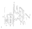
    • Fig. 1 is a schematic diagram showing an example of the system for continuously manufacturing a liquid crystal display panel;
    • Fig. 2 is a schematic diagram showing an example of the inspection apparatus;
    • Figs. 3A and 3b are schematic diagrams showing an example of the inspection process;
    • Fig. 4 is a schematic diagram showing an example of the inspection apparatus;
    • Fig. 5 is a flow chart showing an example of the process flow in the inspection apparatus;
    • Figs. 6A to 6C are schematic diagrams showing an example of the process of feeding a liquid crystal display panel from standby for inspection to the end of inspection; and
    • Figs. 7A and 7B are schematic diagrams showing a conventional inspection apparatus and a light leakage image.
    DETAILED DESCRIPTION OF THE PREFERRED EMBODIMENTS
  • The system and the method for continuously manufacturing a liquid crystal display panel are more specifically described with reference to Fig. 1. It will be understood that the embodiments are not intended to limit the scope of the invention.
  • Embodiment 1
  • In this embodiment, a system for continuously manufacturing a liquid crystal display panel is that a system is arranged a manufacturing apparatus 100 and a inspection apparatus 300, respectively on a continuous feeder 400 for feeding the liquid crystal cell 4 and the liquid crystal display panel Y. The manufacturing apparatus 100 manufactures a liquid crystal display panel Y by a process including cutting a first long polarizing plate 11 and a second long polarizing plate 21, respectively, to form a first polarizing plate 13 and a second polarizing plate 23, while feeding the first long polarizing plate 11 and the second long polarizing plate 21 from a first polarizing plate roll 1 and a second polarizing plate roll 2, respectively, and bonding the first polarizing plate 13 and the second polarizing plate 23 to both sides of a liquid crystal cell 4, which is being fed, in such a manner that their absorption axes are perpendicular to each other. The inspection apparatus 300 optically inspects the liquid crystal display panel Y being fed. The inspection apparatus 300 includes a light application unit 311 which is placed on one side with respect to the feeder 400 so as to apply a line-shaped light beam L to the liquid crystal display panel Y being fed by the feeder 400, wherein the line-shaped light beam L is parallel to the width direction d2 (perpendicular to the drawing plane of Fig. 1) of the feeder 400; and image pickup units (312, 314) that are placed on the other side with respect to the feeder 400 and disposed in positions tilted at a predetermined angle to the feed direction d1 of the feeder 400 and the direction opposite thereto, respectively, with respect to the direction P in which the line-shaped light beam L is applied from the light application unit 311, wherein the image pickup units are for continuously imaging the region irradiated with the line-shaped light beam L in the liquid crystal display panel Y being fed by the feeder 400, and the imaging is performed in a line pattern parallel to the width direction d2 of the feeder 400.
  • Polarizing Plate Rolls
  • For example, the polarizing plate roll, which is formed by winding a long polarizing plate, may be (1) a roll of an optical film laminate that is in the form of a continuous web and includes a carrier film and a pressure-sensitive adhesive-containing long polarizing plate formed on the carrier film. In this case, the system for continuously manufacturing a liquid crystal display panel further includes a cutting apparatus for forming pieces of the polarizing plate (sheet pieces) from the long polarizing plate by cutting (half-cutting or forming score lines in) the long polarizing plate (including the pressure-sensitive adhesive) at predetermined intervals in a direction perpendicular to the feed direction of the carrier film, while the carrier film is left uncut. Alternatively, for example, the polarizing plate roll may be (2) a roll of an optical film laminate including a carrier film and pieces of the polarizing plate (including the pressure-sensitive adhesive), which are formed on the carrier film and placed adjacent to one another with a score line interposed between the adjacent pieces (a roll of a so-called scored polarizing plate).
  • For example, the polarizing plate roll 1 shown in Fig. 1 is a roll of a first optical film laminate 10 including a first carrier film 12 and a long polarizing plate 11 (including a pressure-sensitive adhesive) that has an absorption axis parallel to the feed direction (longitudinal direction) and is formed on the first carrier film 12 with the pressure-sensitive adhesive interposed therebetween. For example, the polarizing plate roll 2 is a roll of a second optical film laminate 20 including a second carrier film 22 and a long polarizing plate 21 (including a pressure-sensitive adhesive) that has an absorption axis parallel to the feed direction (longitudinal direction) and is formed on the second carrier film 22 with the pressure-sensitive adhesive interposed therebetween. For example, the polarizing plate includes a polarizer (about 5 to about 80 µm in thickness) and a polarizer protecting film or films (generally about 1 to about 500 µm in thickness) farmed on one or both sides of the polarizer with or without an adhesive. The optical film laminate 10 may further include any other film component such as a retardation film (generally 10 to 200 µm in thickness), a viewing angle compensation film, a brightness enhancement film, or a surface protecting film. The thickness of the optical film laminate is typically in the range of 10 µm to 500 µm.
  • The pressure-sensitive adhesive interposed between the first or second carrier film 12 or 22 and the polarizing plate is typically, but not limited to, an acryl-based pressure-sensitive adhesive, a silicone pressure-sensitive adhesive, a urethane pressure-sensitive adhesive, or the like. For example, the thickness of the pressure-sensitive adhesive layer is preferably in the range of 10 to 50 µm. For example, the first and second carrier films 12 and 22 to be used may each be such a known conventional film as a plastic film (e.g., a polyethylene terephthalate film or a polyolefin film). According to conventional techniques, any appropriate film such as a film coated with an appropriate release agent such as a silicone, long-chain alkyl or fluoride release agent, or molybdenum sulfide may also be used as needed.
  • Liquid Crystal Display Panel
  • The liquid crystal display panel Y includes a liquid crystal cell 4 and a polarizing plate or plates provided on one or both sides of the liquid crystal cell 4, into which a driving circuit is incorporated as needed. The liquid crystal cell 4 to be used may be of any type such as a vertical alignment (VA) type or an in-plane switching (IPS) type. The liquid crystal cell 4 has a structure including a pair of substrates (first and second substrates) opposed to each other and a liquid crystal layer sealed in between the substrates.
  • Manufacturing Apparatus
  • In this embodiment, the manufacturing apparatus 100 includes a first carrier film feeder 101, a first bonding unit 102, a second carrier film feeder 103, and a second bonding unit 104.
  • While feeding the first long polarizing plate 11 (first optical film laminate 10) from the first polarizing plate roll 1, the first carrier film feeder 101 cuts the first polarizing plate 11 (including the pressure-sensitive adhesive) to form a first polarizing plate 111, peels off the first polarizing plate 111 (including the pressure-sensitive adhesive) from the first carrier film 12, and supplies the first polarizing plate 111 to the first bonding unit 102. For this purpose, the first carrier film feeder 101 includes a first cutting unit 35, a first dancer roller 30, a first peeling unit 40, and a first take-up unit 60.
  • The first cutting unit 35 holds the first optical film laminate 10 from the first carrier film 12 side by a suction unit 35a and cuts the first long polarizing plate 11 in the width direction to form the first polarizing plate 111 on the first carrier film 12. For example, the first cutting unit 35 includes a cutter, a laser, or the like.
  • The first dancer roller 30 has the function of maintaining tension on the first carrier film 12.
  • The first peeling unit 40 inwardly folds back the first carrier film 12 at its front end to peel off the first polarizing plate 111 from the first carrier film 12. In this embodiment, a sharp knife edge is used as a non-limiting example of the front end of the first peeling unit 40.
  • The first take-up unit 60 takes up the first carrier film 12 from which the first polarizing plate 111 is peeled off.
  • The first bonding unit 102 bonds the first polarizing plate 111 from the upper side to the liquid crystal cell 4, which is fed by the feeder 400, with the pressure-sensitive adhesive interposed therebetween, when the first polarizing plate 111 is peeled off from the first carrier film 12 by the first peeling unit 40. In this embodiment, the first bonding unit 102 includes a first bonding roller 50a and a first drive roller 50b.
  • Each unit or apparatus as described above may be used as each apparatus for bonding the second polarizing plate 211 to the other side of the liquid crystal cell 4. Specifically, the second carrier film feeder 103 may have the same device configuration as the first carrier film feeder 101, and the second bonding unit 104 may have the same device configuration as the first bonding unit 102. For example, a second dancer roller 30 may have the same device configuration as the first dancer roller 30, a second take-up unit 60 may have the same device configuration as the first take-up unit 60, and a second bonding roller 50a and a second drive roller 50b may have the same mechanism as the first bonding roller 50a and the first drive roller 50b.
  • Inspection Apparatus
  • The inspection apparatus 300 includes: a light application unit 311 which is placed on one side (the lower side) with respect to the feeder 400 in Fig. 1 so as to apply a line-shaped light beam L to the liquid crystal display panel Y being fed by the feeder 400, wherein the light beam L is parallel to the width direction d2 of the feeder 400; and image pickup units (a first image pickup unit 312 and a second image pickup unit 314) that are placed on the other side (upper side) with respect to the feeder 400 in Fig. 1 and each disposed in a position tilted at a predetermined angle to the feed direction d1 of the feeder 400 or the direction opposite thereto with respect to the direction P in which the line-shaped light beam L is applied from the light application unit 311, wherein the image pickup units are for continuously imaging the region irradiated with the line-shaped light beam L in the liquid crystal display panel Y being fed by the feeder 400, and the imaging is performed in a line pattern parallel to the width direction d2 of the feeder 400. It will be understood that the light application unit 311 may be placed on the upper side with respect to the feeder 400, and the image pickup units may be placed on the lower side with respect to the feeder 400, depending on the state of the liquid crystal display panel Y to be inspected.
  • Light Application Unit
  • The light application unit 311 applies a line-shaped light beam L perpendicularly to the surface of the liquid crystal display panel Y. The light application unit 311 may be any unit capable of applying a line-shaped light beam L traveling in a straight line, examples of which include a halogen lamp, a metal halide lamp, and an LED line light. The line-shaped light beam L extends in a line shape in the width direction d2 of the feeder 400, and the transverse width of the line-shaped light beam L (in a direction parallel to the feed direction d1 of the feeder 400) is shorter than the feed-direction length of the liquid crystal display panel. The light application unit 311 may further include a lens part for reducing the transverse width of the line-shaped light beam L. For example, the lens part may include a cylindrical rod lens formed along the longitudinal direction of the line-shaped light beam. The line-shaped light beam is preferably concentrated in such a manner that its transverse width can be reduced, because such concentration makes it possible to apply high-intensity light to the surface of the liquid crystal display panel and to reduce the arithmetic processing time (or to increase the processing speed) by using small-area image data to keep the data processing capacity small, so that high inspection precision can be obtained. The distance between the light application unit 311 and the feeder 400 may be appropriately controlled depending on the type or size of the liquid crystal display panel, the feed speed, or the like.
  • Image Pickup Units
  • The image pickup units include a first image pickup unit 312 and a second image pickup unit 314. The first image pickup unit 312 is placed in a position tilted at a predetermined angle (θ1) to a direction opposite to the feed direction d1 of the liquid crystal display panel Y with respect to the direction P in which the line-shaped light beam L is applied from the light application unit 311. The second image pickup unit 314 is placed in a position tilted at a predetermined angle (θ2) to the feed direction d1 of the liquid crystal display panel Y with respect to the direction P in which the line-shaped light beam L is applied from the light application unit 311. In this embodiment, the first and second image pickup units 312 and 314 are symmetrically arranged in the feed direction d1 of the liquid crystal display panel Y and the direction opposite thereto. In other words, as shown in Fig. 2, the first and second image pickup units 312 and 314 are symmetrically (θ1=θ2) arranged with respect to the plane (transmitted light plane) formed by the line-shaped light beam L applied from the light application unit 311.
  • The predetermined angle (θ1, θ2) and the distance between the first or second image pickup unit 312 or 314 and the feeder 400 are appropriately determined depending on the type or size of the liquid crystal display panel, the feed speed, or the like. For example, the predetermined angle (θ1, θ2) may be in the range of 1° to 45°, preferably in the range of 10° to 40° for high precision inspection. The number of the image pickup units is not limited to 2, and one image pickup unit or three or more image pickup units may be provided. The angles θ1 and θ2 at which the first and second image pickup units 312 and 314 are tilted, respectively, may be different from each other. For example, the first and second image pickup units 312 and 314 may each include CCD cameras arranged in a line pattern or an optical camera such as a line sensor camera. In this embodiment, two cameras (not shown) are arranged parallel to the width direction d2 in each of the first and second image pickup units 312 and 314, which is not intended to limit how many and how the cameras are arranged.
  • In this embodiment, when there is a foreign body between the liquid crystal cell 4 and the polarizing plate 111 or the polarizing plate 211, as shown in Fig. 3A, the first and second image pickup units 312 and 314 can selectively image the light scattered by the foreign body. As shown in Fig. 3B, therefore, the first and second image pickup units 312 and 314 can image the foreign body with a sharper contrast than that in the above case shown in Figs. 7A and 7B.
  • Feeder
  • The feeder 400 is a continuous feeder for feeding the liquid crystal cell 4 and the liquid crystal display panel Y including the liquid crystal cell 4 and the first and second polarizing plates 13 and 23 bonded to both sides thereof. For example, the feeder 400 is configured to include feed rollers 70, suction plates and so on. In this embodiment, the feeder 400 includes a turning mechanism for horizontally turning by 90° the liquid crystal cell 4 with the first polarizing plate 13 bonded thereto and a turnover mechanism for turning over the liquid crystal cell 4 with the first polarizing plate 13 bonded thereto. During the inspection by the inspection apparatus 300, the feeder 400 also feeds the liquid crystal display panel Y in such a manner that the absorption axis of each of the polarizing plates 111 and 211 is parallel or perpendicular to the feed direction d1.
  • Flow of Inspection and Other Processes
  • In this embodiment, whether the liquid crystal display panel Y is non-defective or defective is determined based on the image data obtained using the first and second image pickup units 312 and 314. For this purpose, as shown in Fig. 4, the inspection apparatus 300 further includes a first image processing unit 313, a second image processing unit 315, a memory 302, an image compiling/assembling unit 303, and a non-defective/defective determining unit 301. A description is given with reference to Figs. 4 to 6A-6C.
  • First, a control unit (not shown) controls the feeder 400 so that the liquid crystal display panel Y is temporarily stopped at a standby position where it waits for the inspection (see Fig. 6A). The control unit then controls the feeder 400 and the inspection apparatus 300 to start the feeding of the liquid crystal display panel Y (step S1) and to start the inspection by the inspection apparatus 300 (step S2).
  • In this inspection, the control unit controls the feeder 400 to continue feeding the liquid crystal display panel Y in the feed direction d1 from the start to the end of the inspection. During this process, the control unit also controls the inspection apparatus 300 so that the light application unit 311 applies the line-shaped light beam L to the liquid crystal display panel Y and that the region irradiated with the line-shaped light beam L in the liquid crystal display panel Y is imaged in a line pattern by the first and second image pickup units 312 and 314. The line-shaped image data taken by the first and second image pickup units 312 and 314 is processed by the first and second image processing units 313 and 315, and each piece of processed line-shaped image data is stored in a memory 302 (step S3, S4. Fig. 6B shows a state at a certain point in the inspection.). As shown in Fig. 5, the steps are sequentially performed until the control unit (not shown) controls the feeder 400 so that the liquid crystal display panel Y is fed to the inspection-end position (see Fig. 6C).
  • The image compiling/assembling unit 303 then reads the line-shaped image data, which has been processed in the first image processing unit 313, from the memory 302, and compiles the images to form the data of a first entire image of the liquid crystal display panel Y (step 5), and subsequently, the first entire image data is stored in the memory 302 (step 6). The image compiling/assembling unit 303 also reads the line-shaped image data, which has been processed in the second image processing unit 315, from the memory 302, and compiles the images to form the data of a second entire image of the liquid crystal display panel Y (step 5), and subsequently, the second entire image data is also stored in the memory 302 (step 6).
  • The non-defective/defective determining unit 301 then reads the first entire image data from the memory 302 and determines, based on the first entire image data, whether the liquid crystal display panel Y is non-defective or defective (step S7). If the non-defective/defective determining unit 301 determines, in this step, that the liquid crystal display panel Y is non-defective, the non-defective/defective determining unit 301 then reads the second entire image data from the memory 302 and determines, based on the second entire image data, whether the liquid crystal display panel Y is non-defective or defective (step S8). If the non-defective/defective determining unit 301 determines, also in this step, that the liquid crystal display panel Y is non-defective, the determination result indicating that the panel Y is non-defective is associated with liquid crystal display panel Y identification information and the like, and stored in the memory 302 (step S9), and the liquid crystal display panel Y is fed to a non-defective product part by the feeder 400. On the other hand, if the non-defectivede/defective determining unit 301 determines, in step S7 or S8, that the liquid crystal display panel Y is defective, the determination result indicating that the panel Y is defective is associated with liquid crystal display panel Y identification information and the like, and stored in the memory 302 (step S10), and the liquid crystal display panel Y is fed to a defective product port by the feeder 400.
  • Method for Continuously Manufacturing Liquid Crystal Display Panel
  • In this embodiment, a method for continuously manufacturing a liquid crystal display panel includes, as shown in Fig. 1, a manufacturing step that includes cutting a first long polarizing plate 11 and a second long polarizing plate 21, respectively, to form a first polarizing plate 111 and a second polarizing plate 211, while feeding the first long polarizing plate 11 (first optical film laminate 10) and the second long polarizing plate 21 (second optical film laminate 20) from a first polarizing plate roll 1 and a second polarizing plate roll 2, respectively, and bonding the first polarizing plate 111 and the second polarizing plate 211 to both sides of a liquid crystal cell 4, which is being fed, in such a manner that their absorption axes are perpendicular to each other, so that a liquid crystal display panel Y is manufactured; and an inspection step that includes optically inspecting the liquid crystal display panel Y being fed, wherein
    the manufacturing step and the inspection step are performed on a continuous feeder 400 for feeding the liquid crystal cell 4 and the liquid crystal display panel Y, and
    the inspection step includes applying a line-shaped light beam L from one side with respect to the feeder 400 to the liquid crystal display panel Y being fed by the feeder 400, wherein the line-shaped light beam L is parallel to the width direction d2 of the feeder 400; and imaging the region irradiated with the line-shaped light beam L in the liquid crystal display panel Y, wherein the imaging is continuously performed in a line pattern parallel to the width direction d2 of the feeder 400 and performed at a position that is on the other side with respect to the feeder 400 and tilted at a predetermined angle to the feed direction d1 of the feeder 400 or the direction opposite thereto with respect to the direction in which the line-shaped light beam L is applied.
  • The line-shaped light beam is preferably applied in a direction perpendicular to the liquid crystal display panel Y. The region irradiated with the line-shaped light beam L in the liquid crystal display panel Y is preferably imaged at positions tilted at a predetermined angle to the feed direction d1 of the liquid crystal display panel Y and the direction opposite thereto with respect to the direction P in which the line-shaped light beam L is applied. The region irradiated with the line-shaped light beam L in the liquid crystal display panel Y is more preferably imaged at positions symmetrically tilted to the feed direction d1 of the liquid crystal display panel Y and the direction opposite thereto with respect to the direction P in which the line-shaped light beam L is applied.
  • Other Embodiments
  • In the above embodiment, the first polarizing plate 111 is bonded to the liquid crystal cell 4 from the upper side, and then after the liquid crystal cell 4 with the first polarizing plate 111 bonded thereto is turned over (upside down and optionally turned by 90°), the second polarizing plate 211 is bonded to the liquid crystal cell 4 from the upper side. Alternatively, the first polarizing plate may be bonded to the liquid crystal cell from the lower side, and then after the liquid crystal cell is turned over, the second polarizing plate may be bonded to the liquid crystal cell from the lower side. Alternatively, after the first polarizing plate is bonded to the liquid crystal cell from the upper side, the second polarizing plate may be bonded to the liquid crystal cell from the lower side without turning over the liquid crystal cell, or after the first polarizing plate is bonded to the liquid crystal cell from the lower side, the second polarizing plate may be bonded to the liquid crystal cell from the upper side without turning over the liquid crystal cell. Alternatively, the first and second polarizing plates may be simultaneously bonded to the liquid crystal cell from the upper and lower sides.
  • In the above embodiment, the long polarizing plate is fed from the polarizing plate roll and cut at predetermined intervals. In the invention, this feature is non-limiting. Alternatively, for example, the long polarizing plate fed from the polarizing plate roll may be inspected for defects and cut in such a manner that defects are avoided based on the result of the inspection (by so-called skip cutting). Alternatively, defect information previously attached to the long polarizing plate or marks placed at defect positions may be read out, and the long polarizing plate may be cut in such a manner that defects are avoided based on the defect information or marks.
  • In the above embodiment, the long polarizing plates each have an absorption axis parallel to the longitudinal direction, but the direction of the absorption axis of the long polarizing plate is not limited thereto. Alternatively, for example, the first long polarizing plate may have an absorption axis parallel to the transverse direction (width direction), and the second long polarizing plate may have an absorption axis parallel to the longitudinal direction. In this case, the turning mechanism for horizontally turning by 90° the liquid crystal cell with the first polarizing plate bonded thereto may be omitted as needed.
  • EXAMPLES
  • In an example, the inspection apparatus 300 shown in Fig. 3A is used. In the inspection apparatus 300, the light application unit 311 is placed below the feeder 400 so as to apply, to the liquid crystal display panel Y, a line-shaped light beam L parallel to the width direction d2 of the feeder 400. The first image pickup unit 312 is placed above the feeder 400 and disposed in a position tilted at 30° (θ1) to the direction opposite to the feed direction d1 of the feeder 400 with respect to the direction P in which the line-shaped light beam L is applied. The region irradiated with the line-shaped light beam L in the liquid crystal display panel Y being fed by the feeder 400 is continuously imaged in a line pattern parallel to the width direction d2 of the feeder 400 by the first image pickup unit 312. The second image pickup unit 314 is placed above the feeder 400 and disposed in a position tilted at 30° (θ2) to the feed direction d1 of the feeder 400 with respect to the direction P in which the line-shaped light beam L is applied. The region irradiated with the line-shaped light beam L in the liquid crystal display panel Y being fed by the feeder 400 is also continuously imaged in a line pattern parallel to the width direction d2 of the feeder 400 by the second image pickup unit 314. The first and second image pickup units 312 and 314 are symmetrically arranged with respect to the direction P in which the line-shaped light beam L is applied.
  • In a comparative example, the inspection apparatus 370 shown in Fig. 7A is used. In the inspection apparatus 370, the image pickup unit 371 (not tilted) is placed opposite to the light application unit 311.
  • Each light application unit 311 used was a metal halide lamp (Model LS-M250A-D24 manufactured by SUMITA OPTICAL GLASS, Inc.), and a camera (Model PCME8020 manufactured by FUTEC INC.) was used in each of the image pickup units 312, 314, and 371.
  • Using the manufacturing apparatus 100 shown in Fig. 1, the polarizing plates 111 and 211 were bonded to both sides of the liquid crystal cell 4 in such a manner that their absorption axes were perpendicular to each other, so that the liquid crystal display panel Y was obtained. The liquid crystal cell 4 was a 32 inch TV size cell having glass substrates. The polarizing plates 111 and 211 were VEG1724DU manufactured by NITTO DENKO CORPORATION.
  • The manufactured liquid crystal display panels Y were visually inspected. The visual inspection was performed to previously obtain 200 defective samples, which were each determined to be defective due to a foreign body or bodies between the liquid crystal cell 4 and the polarizing plate 111 or 211. The defective samples were inspected using each of the inspection apparatus 300 (Fig. 3A) of the example and the inspection apparatus 370 (Fig. 7A) of the comparative example, and how many samples were not determined to be defective (the number of missed samples) was evaluated. In both of the example and the comparative example, the speed at which the liquid crystal display panel Y is fed by the feeder 400 during the inspection was set at 36 m/minute. The evaluation results are shown in Table 1.
  • Table 1
    Light application unit Image pickup unit Number of missed samples (n=200)
    Direction of application of line-shaped light Tilt angle with respect to the line-shaped light application direction θ (θ1, θ2)
    Examples Perpendicular to liquid crystal display panel 30° 0
    Comparative examples Perpendicular to liquid crystal display panel 15
  • The results in Table 1 show that while the inspection apparatus 370 of the comparative example missed 15 samples, the inspection apparatus 300 of the example missed no sample. It was found that the inspection using the inspection apparatus 300 of the example was performed at the same level of precision as the visual inspection, which demonstrated that the inspection apparatus 300 of the example was effective.

Claims (10)

  1. A method for continuously manufacturing a liquid crystal display panel, comprising:
    a manufacturing step that comprises cutting a first long polarizing plate to form a first polarizing plate while feeding the first long polarizing plate from a first polarizing plate roll and bonding the first polarizing plate to first side of a liquid crystal cell which is being fed, and
    cutting a second long polarizing plate to form a second polarizing plate while feeding the second long polarizing plate from a second polarizing plate roll and bonding the second polarizing plate to second side of the liquid crystal cell which is being fed in such a manner that absorption axis of the first polarizing plate and absorption axis of the second polarizing plate are perpendicular to each other, so that a liquid crystal display panel is manufactured; and
    an inspection step of optically inspecting the liquid crystal display panel being fed, wherein
    the manufacturing step and the inspection step are performed on a continuous feeder for feeding the liquid crystal cell and the liquid crystal display panel, and
    the inspection step comprises: applying a line-shaped light beam from one side with respect to the feeder to the liquid crystal display panel being fed by the feeder, wherein the line-shaped light beam is parallel to a width direction of the feeder; and imaging a region irradiated with the line-shaped light beam in the liquid crystal display panel, wherein the imaging is continuously performed in a line pattern parallel to a width direction of the feeder and performed at a position that is on another side with respect to the feeder and tilted at a predetermined angle to a feed direction of the feeder or a direction opposite thereto with respect to a direction in which the line-shaped light beam is applied.
  2. The method according to claim 1, wherein the line-shaped light beam is applied in a direction perpendicular to the liquid crystal display panel.
  3. The method according to claim 1, wherein the region irradiated with the line-shaped light beam in the liquid crystal display panel is imaged in a line pattern at positions tilted at a predetermined angle to the feed direction of the liquid crystal display panel and the direction opposite thereto with respect to the direction in which the line-shaped light beam is applied.
  4. The method according to claim 3, wherein the region irradiated with the line-shaped light beam in the liquid crystal display panel is imaged in a line pattern at positions symmetrically tilted to the feed direction of the liquid crystal display panel and the direction opposite thereto with respect to the direction in which the line-shaped light beam is applied.
  5. The method according to claim 1, wherein in the imaging, the region irradiated with the line-shaped light beam in the liquid crystal display panel is imaged in a line pattern at a position or positions tilted at an angle of 1° to 45° with respect to the direction in which the line-shaped light beam is applied.
  6. A method for optically inspecting a liquid crystal display panel being fed by a feeder, comprising:
    applying a line-shaped light beam from one side with respect to the feeder to the liquid crystal display panel being fed by the feeder, wherein the line-shaped light beam is parallel to a width direction of the feeder; and
    imaging a region irradiated with the line-shaped light beam in the liquid crystal display panel, wherein the imaging is continuously performed in a line pattern parallel to a width direction of the feeder and performed at a position that is on another side with respect to the feeder and tilted at a predetermined angle to a feed direction of the feeder or a direction opposite thereto.
  7. The method according to claim 6, wherein the line-shaped light beam is applied in a direction perpendicular to the liquid crystal display panel.
  8. The method according to claim 6, wherein the region irradiated with the line-shaped light beam in the liquid crystal display panel is imaged in a line pattern at positions tilted at a predetermined angle to the feed direction of the liquid crystal display panel and the direction opposite thereto with respect to the direction in which the line-shaped light beam is applied.
  9. The method according to claim 8, wherein the region irradiated with the line-shaped light beam in the liquid crystal display panel is imaged in a line pattern at positions symmetrically tilted to the feed direction of the liquid crystal display panel and the direction opposite thereto with respect to the direction in which the line-shaped light beam is applied.
  10. The method according to claim 16, wherein in the imaging, the region irradiated with the line-shaped light beam in the liquid crystal display panel is imaged in a line pattern at a position or positions tilted at an angle of 1° to 45° with respect to the direction in which the line-shaped light beam is applied.
EP11185696A 2011-03-18 2011-10-19 Method for continuously manufacturing liquid crystal display panel and inspection method Withdrawn EP2500766A1 (en)

Applications Claiming Priority (1)

Application Number Priority Date Filing Date Title
JP2011060335A JP4921597B1 (en) 2011-03-18 2011-03-18 Liquid crystal display panel continuous manufacturing system, liquid crystal display panel continuous manufacturing method, inspection apparatus and inspection method

Publications (1)

Publication Number Publication Date
EP2500766A1 true EP2500766A1 (en) 2012-09-19

Family

ID=44799894

Family Applications (1)

Application Number Title Priority Date Filing Date
EP11185696A Withdrawn EP2500766A1 (en) 2011-03-18 2011-10-19 Method for continuously manufacturing liquid crystal display panel and inspection method

Country Status (6)

Country Link
US (1) US8540543B2 (en)
EP (1) EP2500766A1 (en)
JP (1) JP4921597B1 (en)
KR (1) KR101271936B1 (en)
CN (2) CN102681242B (en)
TW (1) TWI456290B (en)

Families Citing this family (6)

* Cited by examiner, † Cited by third party
Publication number Priority date Publication date Assignee Title
JP5782010B2 (en) * 2012-11-09 2015-09-24 日東電工株式会社 Optical display panel continuous manufacturing method and optical display panel continuous manufacturing system
TWI477803B (en) * 2013-03-05 2015-03-21 Largan Precision Co Ltd Photographing lens assembly
JP6255186B2 (en) * 2013-08-07 2017-12-27 日東電工株式会社 Optical member inspection method, optical product manufacturing method, and optical member inspection apparatus
KR20150052457A (en) 2013-11-05 2015-05-14 삼성디스플레이 주식회사 Method of attaching polarizing plate
JP6529250B2 (en) * 2014-12-18 2019-06-12 日東電工株式会社 Optical display panel manufacturing method and optical display panel manufacturing system
JP7051445B2 (en) 2018-01-10 2022-04-11 日東電工株式会社 Continuous inspection method and continuous inspection device for optical display panel, and continuous manufacturing method and continuous manufacturing system for optical display panel.

Citations (5)

* Cited by examiner, † Cited by third party
Publication number Priority date Publication date Assignee Title
JPH06235624A (en) * 1992-12-15 1994-08-23 Hitachi Ltd Inspecting method and apparatus for transparent sheet
JP2003262843A (en) * 2002-03-11 2003-09-19 Seiko Epson Corp Method and device for inspecting liquid crystal panel
JP2005351825A (en) * 2004-06-14 2005-12-22 Nitto Denko Corp Defect inspection device
US20060203246A1 (en) * 2005-03-10 2006-09-14 Fuji Photo Film Co., Ltd. Apparatus and method for inspecting film defect
JP2010170126A (en) 2008-12-25 2010-08-05 Nitto Denko Corp Method and apparatus for manufacturing liquid crystal display device

Family Cites Families (14)

* Cited by examiner, † Cited by third party
Publication number Priority date Publication date Assignee Title
JPH04178545A (en) * 1990-11-14 1992-06-25 Fuji Photo Film Co Ltd Method and apparatus for inspecting transparent band-like body
JPH08152416A (en) * 1994-09-28 1996-06-11 Toray Ind Inc Defect detecting device for sheet-shaped object
JP3224083B2 (en) * 1996-10-29 2001-10-29 セントラル硝子株式会社 Method and apparatus for detecting defects in sheet glass
JPH11248643A (en) * 1998-03-02 1999-09-17 Sekisui Chem Co Ltd Detection device for foreign matter in transparent film
JP3078524B2 (en) * 1998-03-06 2000-08-21 富士電線電器株式会社 Defect detection device
JP2000028546A (en) * 1998-07-08 2000-01-28 Fuji Photo Film Co Ltd Defect inspecting method and device for optically compensating film
JP3316501B2 (en) * 2000-03-28 2002-08-19 科学技術振興事業団 Sensor head, luminance distribution measuring device including the same, and display unevenness evaluation device
JP2004301882A (en) * 2003-03-28 2004-10-28 Fujitsu Display Technologies Corp Method for defecting detect of liquid crystal display panel
JP2005127989A (en) * 2003-10-03 2005-05-19 Olympus Corp Flaw detector and flaw detecting program
JP2006078317A (en) * 2004-09-09 2006-03-23 Seiko Epson Corp Inspection method for body under inspection and its device
KR100642500B1 (en) * 2005-03-02 2006-11-06 (주)쎄미시스코 Apparatus for edge defect and discolor testing of glass board
KR100734749B1 (en) * 2005-03-31 2007-07-03 에버테크노 주식회사 Polarizing Film Inspecting Apparatus and Method
JP2007256106A (en) * 2006-03-23 2007-10-04 Sharp Corp Display panel inspection device and display panel inspection method using the same
JP4855493B2 (en) * 2008-04-14 2012-01-18 日東電工株式会社 Optical display device manufacturing system and optical display device manufacturing method

Patent Citations (5)

* Cited by examiner, † Cited by third party
Publication number Priority date Publication date Assignee Title
JPH06235624A (en) * 1992-12-15 1994-08-23 Hitachi Ltd Inspecting method and apparatus for transparent sheet
JP2003262843A (en) * 2002-03-11 2003-09-19 Seiko Epson Corp Method and device for inspecting liquid crystal panel
JP2005351825A (en) * 2004-06-14 2005-12-22 Nitto Denko Corp Defect inspection device
US20060203246A1 (en) * 2005-03-10 2006-09-14 Fuji Photo Film Co., Ltd. Apparatus and method for inspecting film defect
JP2010170126A (en) 2008-12-25 2010-08-05 Nitto Denko Corp Method and apparatus for manufacturing liquid crystal display device

Also Published As

Publication number Publication date
CN102681242A (en) 2012-09-19
US20120238176A1 (en) 2012-09-20
CN202351564U (en) 2012-07-25
US8540543B2 (en) 2013-09-24
JP4921597B1 (en) 2012-04-25
KR20120106505A (en) 2012-09-26
KR101271936B1 (en) 2013-06-07
CN102681242B (en) 2014-12-31
JP2012194509A (en) 2012-10-11
TW201239455A (en) 2012-10-01
TWI456290B (en) 2014-10-11

Similar Documents

Publication Publication Date Title
US8709181B2 (en) Method for manufacturing optical display device and material roll for use therein
US8114237B2 (en) Method for producing material roll
EP2312381B1 (en) A roll of continuous optical film laminate with predefined slit lines, and method and apparatus for manufacturing the same
US9239416B2 (en) System and method for manufacturing optical display device, set of material rolls and method for manufacture thereof
US8187048B2 (en) System and method for manufacturing optical display device
US8404334B2 (en) Continuous web of optical film laminate with predefined slit lines, and method and system for manufacturing the same
US8540543B2 (en) Method for continuously manufacturing liquid crystal display panel and inspection method
KR20030093956A (en) Method for inspecting polarizing film and apparatus for the method
JP4913838B2 (en) Optical display device manufacturing system and optical display device manufacturing method
CN110018582B (en) Optical display panel continuous inspection method and apparatus, continuous manufacturing method and system

Legal Events

Date Code Title Description
PUAI Public reference made under article 153(3) epc to a published international application that has entered the european phase

Free format text: ORIGINAL CODE: 0009012

AK Designated contracting states

Kind code of ref document: A1

Designated state(s): AL AT BE BG CH CY CZ DE DK EE ES FI FR GB GR HR HU IE IS IT LI LT LU LV MC MK MT NL NO PL PT RO RS SE SI SK SM TR

AX Request for extension of the european patent

Extension state: BA ME

17P Request for examination filed

Effective date: 20130319

STAA Information on the status of an ep patent application or granted ep patent

Free format text: STATUS: THE APPLICATION HAS BEEN WITHDRAWN

18W Application withdrawn

Effective date: 20141203