EP2500601A1 - Worm wheel - Google Patents
Worm wheel Download PDFInfo
- Publication number
- EP2500601A1 EP2500601A1 EP10829669A EP10829669A EP2500601A1 EP 2500601 A1 EP2500601 A1 EP 2500601A1 EP 10829669 A EP10829669 A EP 10829669A EP 10829669 A EP10829669 A EP 10829669A EP 2500601 A1 EP2500601 A1 EP 2500601A1
- Authority
- EP
- European Patent Office
- Prior art keywords
- worm wheel
- forming member
- core member
- gear forming
- plastic material
- Prior art date
- Legal status (The legal status is an assumption and is not a legal conclusion. Google has not performed a legal analysis and makes no representation as to the accuracy of the status listed.)
- Granted
Links
Images



Classifications
-
- F—MECHANICAL ENGINEERING; LIGHTING; HEATING; WEAPONS; BLASTING
- F16—ENGINEERING ELEMENTS AND UNITS; GENERAL MEASURES FOR PRODUCING AND MAINTAINING EFFECTIVE FUNCTIONING OF MACHINES OR INSTALLATIONS; THERMAL INSULATION IN GENERAL
- F16H—GEARING
- F16H55/00—Elements with teeth or friction surfaces for conveying motion; Worms, pulleys or sheaves for gearing mechanisms
- F16H55/02—Toothed members; Worms
- F16H55/06—Use of materials; Use of treatments of toothed members or worms to affect their intrinsic material properties
-
- B—PERFORMING OPERATIONS; TRANSPORTING
- B62—LAND VEHICLES FOR TRAVELLING OTHERWISE THAN ON RAILS
- B62D—MOTOR VEHICLES; TRAILERS
- B62D5/00—Power-assisted or power-driven steering
- B62D5/04—Power-assisted or power-driven steering electrical, e.g. using an electric servo-motor connected to, or forming part of, the steering gear
- B62D5/0409—Electric motor acting on the steering column
-
- F—MECHANICAL ENGINEERING; LIGHTING; HEATING; WEAPONS; BLASTING
- F16—ENGINEERING ELEMENTS AND UNITS; GENERAL MEASURES FOR PRODUCING AND MAINTAINING EFFECTIVE FUNCTIONING OF MACHINES OR INSTALLATIONS; THERMAL INSULATION IN GENERAL
- F16H—GEARING
- F16H55/00—Elements with teeth or friction surfaces for conveying motion; Worms, pulleys or sheaves for gearing mechanisms
- F16H55/02—Toothed members; Worms
- F16H55/06—Use of materials; Use of treatments of toothed members or worms to affect their intrinsic material properties
- F16H2055/065—Moulded gears, e.g. inserts therefor
-
- F—MECHANICAL ENGINEERING; LIGHTING; HEATING; WEAPONS; BLASTING
- F16—ENGINEERING ELEMENTS AND UNITS; GENERAL MEASURES FOR PRODUCING AND MAINTAINING EFFECTIVE FUNCTIONING OF MACHINES OR INSTALLATIONS; THERMAL INSULATION IN GENERAL
- F16H—GEARING
- F16H55/00—Elements with teeth or friction surfaces for conveying motion; Worms, pulleys or sheaves for gearing mechanisms
- F16H55/02—Toothed members; Worms
- F16H55/22—Toothed members; Worms for transmissions with crossing shafts, especially worms, worm-gears
-
- Y—GENERAL TAGGING OF NEW TECHNOLOGICAL DEVELOPMENTS; GENERAL TAGGING OF CROSS-SECTIONAL TECHNOLOGIES SPANNING OVER SEVERAL SECTIONS OF THE IPC; TECHNICAL SUBJECTS COVERED BY FORMER USPC CROSS-REFERENCE ART COLLECTIONS [XRACs] AND DIGESTS
- Y10—TECHNICAL SUBJECTS COVERED BY FORMER USPC
- Y10T—TECHNICAL SUBJECTS COVERED BY FORMER US CLASSIFICATION
- Y10T74/00—Machine element or mechanism
- Y10T74/19—Gearing
- Y10T74/1987—Rotary bodies
-
- Y—GENERAL TAGGING OF NEW TECHNOLOGICAL DEVELOPMENTS; GENERAL TAGGING OF CROSS-SECTIONAL TECHNOLOGIES SPANNING OVER SEVERAL SECTIONS OF THE IPC; TECHNICAL SUBJECTS COVERED BY FORMER USPC CROSS-REFERENCE ART COLLECTIONS [XRACs] AND DIGESTS
- Y10—TECHNICAL SUBJECTS COVERED BY FORMER USPC
- Y10T—TECHNICAL SUBJECTS COVERED BY FORMER US CLASSIFICATION
- Y10T74/00—Machine element or mechanism
- Y10T74/19—Gearing
- Y10T74/1987—Rotary bodies
- Y10T74/19893—Sectional
- Y10T74/19921—Separate rim
-
- Y—GENERAL TAGGING OF NEW TECHNOLOGICAL DEVELOPMENTS; GENERAL TAGGING OF CROSS-SECTIONAL TECHNOLOGIES SPANNING OVER SEVERAL SECTIONS OF THE IPC; TECHNICAL SUBJECTS COVERED BY FORMER USPC CROSS-REFERENCE ART COLLECTIONS [XRACs] AND DIGESTS
- Y10—TECHNICAL SUBJECTS COVERED BY FORMER USPC
- Y10T—TECHNICAL SUBJECTS COVERED BY FORMER US CLASSIFICATION
- Y10T74/00—Machine element or mechanism
- Y10T74/19—Gearing
- Y10T74/1987—Rotary bodies
- Y10T74/19893—Sectional
- Y10T74/19935—Sheet metal
Definitions
- the present invention relates to a worm wheel, and in particular to a worm wheel for an electric power steering device mounted on a vehicle.
- the electric power steering device (EPS) for a vehicle assists the steering effort of the vehicle operator.
- the steering torque applied to the steering wheel causes an input shaft to rotate, and is transmitted to an output shaft.
- the steering torque transmitted to the output shaft is detected by a torque detecting device, and the steering torque of the output shaft is assisted as required according to the detected steering torque.
- the output shaft is typically affixed with a worm wheel which forms a worm gear mechanism in cooperation with a worm connected to an electric motor and meshing with the worm wheel.
- the EPS activates the electric motor in dependence on the detected steering torque, and this driving torque is transmitted to the output shaft via the worm and the worm wheel to be added to the steering torque.
- the worm wheel is typically formed as a composite structure including a metallic core member affixed to the output shaft and a plastic gear forming member attached to the peripheral part of the core member and provided with teeth that mesh with the worm.
- the metallic core member ensures the worm wheel to be securely attached to the output shaft, and the plastic gear forming member reduces the noises and vibrations caused by the meshing of the gear teeth with the worm. See Patent Document 1.
- Such a worm wheel is made by using the cylindrical core member as an insert and injection molding plastic material around the periphery of the cylindrical core member.
- the plastic material is initially fluid but solidifies during the molding process, and a certain shrinkage occurs to the plastic material.
- This shrinkage causes the plastic material to grip the outer periphery of the cylindrical core member, and owing to the blocking of the shrinking deformation of the plastic material by the core member, some residual stress is produced in the gear forming member during the molding process thereof. This residual stress is known to decrease the tolerable stress level that may be produced in the plastic gear forming member.
- This problem may be alleviated by using a multi-thread (double- or triple-thread) worm gear mechanism, but it requires the size of the worm wheel to be increased so that the space efficiency is impaired.
- the present invention was made in view of such a problem of the prior art, and has a primary object to provide a worm wheel that allows the residual stress in the plastic gear forming member thereof to be reduced, and suited for compact design.
- the present invention is directed to a worm wheel, comprising a metallic core member (30) including a pivot portion (37), and a gear forming member (20) made of plastic material and formed on an outer periphery of the core member.
- the core member includes a boss portion (31) defining the pivot portion, an intermediate portion (32) extending radially from the outer periphery of the boss portion, and a cylindrical portion (33) connected to a radially outer end of the intermediate portion and having the gear forming member molded thereon coaxially with the boss, the cylindrical portion being formed with through holes (34, 36) passed radially therethrough.
- the radial through holes may consist of blind holes (having a closed end) or cutouts made in an axial edge of the outer wall of the cylindrical portion.
- the cylindrical portion the retains the plastic material is formed with radial through holes, the shrinking of the plastic material in the corresponding positions are not blocked so that the residual stress is reduced and the reduction in the mechanical strength of the worm wheel can be avoided.
- the gear forming member may be formed by insert molding the plastic material with the cylindrical portion. Because the cylindrical portion of the core member is inserted in the plastic material, and is therefore wrapped in the plastic material, the strength of attachment between the core member and the gear forming member can be improved.
- the through holes (34, 36) may be formed at positions circumferentially coinciding with (corresponding with) teeth (21) formed on an outer periphery of the gear forming member (20).
- the gear forming member (20) may be formed by a plurality of layers (22, 23) of plastic material.
- the present invention may be implemented in such a manner that the boss position (31) receives an output shaft (2) of an automotive electric power steering device so that the core member (30) is fixedly secured to the output shaft (2).
- the worm gear mechanism consisting of the worm wheel and the worm can be constructed as a highly compact unit, and the space efficiency of the electric power steering device can be improved.
- the residual stress in the plastic gear forming member can be reduced, and the strength of the attachment between the core member and the gear forming member can be increased so the worm wheel can be formed as a highly compact component.
- FIG. 1 is an overall view of an electric power steering device to which the present invention is applied.
- This electric power steering device is provided with an electric motor 5 for generating an assisting steering force that reduces the manual steering effort applied to a steering wheel 101.
- this electric power steering device is further provided with a rack and pinion mechanism 106 including a pinion 10 integrally connected to the steering wheel 101 via a steering shaft 2 in a rotationally fast manner and a rack shaft 12 formed with a rack 11 meshing with the pinion 10 and disposed so as to be laterally moveable with respect to the vehicle body.
- Each end of the rack shaft 12 is provided with a joint 118 protected by a cover 13, and is connected to a knuckle arm 109 of a corresponding front wheel (steerable wheel) 108 via the joint 118 and a tie rod 14 so that the two front wheels 108 are steered in response to the angular movement of the steering wheel 101.
- the drive force of the electric motor 5 is transmitted to the steering shaft 2 via a worm gear mechanism 15 received in a gear box 110 along with the pinion 10.
- the electric motor 5 is controlled by a steering control unit (EPS-ECU) 113 such that the required assisting steering force may be produced by the electric motor 5 according to the output signals received by the steering control unit 113 from a steering angle sensor 114 for detecting the steering angle of the steering wheel 101, a steering torque sensor 115 for detecting the manual steering torque applied to the pinion 10 and a vehicle speed sensor 116 for detecting the vehicle speed.
- EPS-ECU steering control unit
- Figure 2 is a sectional view of the gear box 110 taken along line II-II of Figure 1 .
- the gear box 110 receives therein the worm gear mechanism 15 for transmitting the drive force of the electric motor 5 to the steering shaft 2 at a reduced speed, the rack and pinion mechanism 106 for converting the rotational movement of the steering shaft 2 into the linear movement of the rack shaft 12 and the steering torque sensor 115 for detecting the steering torque acting on the steering shaft 2.
- the worm gear mechanism 15 comprises a worm 4 coaxially connected to the output shaft of the electric motor 5 and a worm wheel 3 fixed fitted coaxially on the steering shaft 2 so that the drive force of the electric motor 5 is transmitted to the worm 4 (drive gear) and the worm wheel 3 (driven gear) is caused to rotate in a corresponding manner.
- the worm 4 comprises a core member 133 consisting of a metallic member such as carbon steel around which a single thread (or tooth) 134 is formed.
- a single thread (or tooth) 134 is formed.
- the worm wheel 3 is described in the following with reference to Figures 4 and 5 .
- the directions in the following description will be based on the directions X, Y and Z show in Figure 3 .
- the worm wheel 3 consists of a metallic core member 30 and a plastic gear forming member 20 formed around the outer periphery of the core member 30.
- the core member 30 may be made of steel, for instance, while the gear forming member 20 may be made of polyamide resin, and formed by injection molding.
- the core member 30 consists of a cylindrical boss portion 31, an intermediate portion 32 extending radially outward from the outer peripheral surface of the boss portion 31 in the form of a plurality of spokes and a cylindrical portion 33 connected to the outer peripheral surface of the intermediate portion 32 and having a common central axial line (Z axis) as the boss portion 31.
- the outer peripheral wall of the cylindrical portion 33 is provided with a serrated outer peripheral surface, and radial through holes 34 in such a manner that the through holes 34 alternate with the projections 35 of the serration on the outer peripheral surface at a regular angular interval.
- the output shaft 2 of the vehicle electric power steering device is fitted into a central bore 37 of the cylindrical boss portion 31 so that the core member 30 is fixedly attached to the output shaft 2 (Refer to Figure 3 , as well).
- the core member 30 is provided with the central bore 37 serving as a pivot portion in the illustrated embodiment, but may also be provided with an integral solid center shaft.
- the intermediate portion 32 joins the boss portion 31 and the cylindrical portion 33 to each other, and may have a number of spokes, an axial thickness and a circumferential width that suit the required mechanical strength of the worm wheel 3.
- the intermediate portion 32 may also be made of a solid disk, for instance.
- the cylindrical portion 33 is given with a greater axial (Z axis) dimension than the intermediate portion 32.
- the plastic material is insert molded such that the plastic material is wrapped around the entirely cylindrical portion 33 and the outer peripheral part of the intermediate portion 32. Thereby, the radial movement of the plastic material is prevented, and a favorable attachment between the core member 30 and the gear forming member 20 can be achieved.
- the through holes 34 are formed in the same phase relationship (in the circumferentially corresponding positions) as the teeth 21 of the gear forming member 20 as shown in the right hand side of the sectional view of Figure 4 .
- the through holes 34 accommodates this shrinkage, and reduces the residual stress that may be produced in the parts of the gear forming member 20 corresponding to the circumferential positions of the through holes 34.
- the through holes 34 are located circumferentially so as to correspond to the teeth 21, the teeth 21 which are required to have a high mechanical strength are prevented from being reduced in mechanical strength.
- the width of the cylindrical portion 33 which is to be inserted in the plastic material can be made narrower than that of the prior art, and the compact and light weight design of the worm wheel is enabled with the added advantage of the reducing in the residual stress.
- the reduction in the residual stress also contributes to the improvement in the precision of the profile of the teeth which are formed by molding.
- the projections 35 in the serration project from the outer periphery of the cylindrical portion 33, and extend a certain distance in the axial (Z axis) direction, and not only prevent the circumferential relative movement between the plastic gear forming member 20 with respect to the cylindrical portion 33 (core member 30) but also increase the bonding strength between the core member 30 and the gear forming member 20 owing to an increased contact area between them.
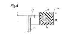
- the gear forming member 20 is initially molded with a first plastic layer 22 and is further over-molded with a second plastic layer 23. According to this arrangement, the unevenness in the residual stress that may be produced as a result of the molding process can be mitigated, and the precision in the gear tooth profile may be improved.
- the thickness of the second plastic layer 23 may be selected such that no new residual stress may be produced.
- a second embodiment of the worm wheel 40 according to the present invention is described in the following with reference to Figure 7 .
- the parts corresponding to those of the first embodiment are denoted with like numerals mostly without repeating the description of such parts, and only the parts of the second embodiment different from those of the first embodiment are described in any detail in the following.
- cutouts 36 are made across the lower edge of the outer peripheral wall of the cylindrical portion 33 at the positions corresponding to those of the through holes 34 in the first embodiment. Similarly as the though holes 34 of the first embodiment, these cutouts 36 accommodate the shrinking of the plastic material in the radial direction, and reduce the residual stress in the parts of the gear forming member 20 corresponding to the circumferential positions of the cutouts 36. By thus providing the cutouts 36 in the circumferential positions corresponding to the teeth 21, the teeth that are required to have a high mechanical strength are prevented from being reduced in mechanical strength.
Landscapes
- Engineering & Computer Science (AREA)
- Mechanical Engineering (AREA)
- General Engineering & Computer Science (AREA)
- Chemical & Material Sciences (AREA)
- Combustion & Propulsion (AREA)
- Transportation (AREA)
- Physics & Mathematics (AREA)
- Electromagnetism (AREA)
- Thermal Sciences (AREA)
- Gears, Cams (AREA)
- Power Steering Mechanism (AREA)
- Gear Transmission (AREA)
Abstract
Description
- The present invention relates to a worm wheel, and in particular to a worm wheel for an electric power steering device mounted on a vehicle.
- The electric power steering device (EPS) for a vehicle assists the steering effort of the vehicle operator. The steering torque applied to the steering wheel causes an input shaft to rotate, and is transmitted to an output shaft. The steering torque transmitted to the output shaft is detected by a torque detecting device, and the steering torque of the output shaft is assisted as required according to the detected steering torque. The output shaft is typically affixed with a worm wheel which forms a worm gear mechanism in cooperation with a worm connected to an electric motor and meshing with the worm wheel. The EPS activates the electric motor in dependence on the detected steering torque, and this driving torque is transmitted to the output shaft via the worm and the worm wheel to be added to the steering torque.
- The worm wheel is typically formed as a composite structure including a metallic core member affixed to the output shaft and a plastic gear forming member attached to the peripheral part of the core member and provided with teeth that mesh with the worm. The metallic core member ensures the worm wheel to be securely attached to the output shaft, and the plastic gear forming member reduces the noises and vibrations caused by the meshing of the gear teeth with the worm. See Patent Document 1.
-
- Patent Document 1:
JP 11-301501A - Such a worm wheel is made by using the cylindrical core member as an insert and injection molding plastic material around the periphery of the cylindrical core member. The plastic material is initially fluid but solidifies during the molding process, and a certain shrinkage occurs to the plastic material. This shrinkage causes the plastic material to grip the outer periphery of the cylindrical core member, and owing to the blocking of the shrinking deformation of the plastic material by the core member, some residual stress is produced in the gear forming member during the molding process thereof. This residual stress is known to decrease the tolerable stress level that may be produced in the plastic gear forming member.
- This problem may be alleviated by using a multi-thread (double- or triple-thread) worm gear mechanism, but it requires the size of the worm wheel to be increased so that the space efficiency is impaired.
- The present invention was made in view of such a problem of the prior art, and has a primary object to provide a worm wheel that allows the residual stress in the plastic gear forming member thereof to be reduced, and suited for compact design.
- The present invention is directed to a worm wheel, comprising a metallic core member (30) including a pivot portion (37), and a gear forming member (20) made of plastic material and formed on an outer periphery of the core member. In particular, the core member includes a boss portion (31) defining the pivot portion, an intermediate portion (32) extending radially from the outer periphery of the boss portion, and a cylindrical portion (33) connected to a radially outer end of the intermediate portion and having the gear forming member molded thereon coaxially with the boss, the cylindrical portion being formed with through holes (34, 36) passed radially therethrough. The radial through holes may consist of blind holes (having a closed end) or cutouts made in an axial edge of the outer wall of the cylindrical portion.
- According to this arrangement, because the cylindrical portion the retains the plastic material is formed with radial through holes, the shrinking of the plastic material in the corresponding positions are not blocked so that the residual stress is reduced and the reduction in the mechanical strength of the worm wheel can be avoided.
- In this arrangement, the gear forming member may be formed by insert molding the plastic material with the cylindrical portion. Because the cylindrical portion of the core member is inserted in the plastic material, and is therefore wrapped in the plastic material, the strength of attachment between the core member and the gear forming member can be improved.
- In such an arrangement, the through holes (34, 36) may be formed at positions circumferentially coinciding with (corresponding with) teeth (21) formed on an outer periphery of the gear forming member (20). By this matching the positions of the teeth with the through holes, the teeth which are subjected to a relatively high stress are prevented from being reduced in mechanical strength.
- In such an arrangement, the gear forming member (20) may be formed by a plurality of layers (22, 23) of plastic material. By thus over-molding the worm wheel which is already molded with plastic material, the unevenness in the residual stress that may be produced during the molding process can be reduced, and the precision in the profile of the teeth can be improved.
- The present invention may be implemented in such a manner that the boss position (31) receives an output shaft (2) of an automotive electric power steering device so that the core member (30) is fixedly secured to the output shaft (2). Thereby, the worm gear mechanism consisting of the worm wheel and the worm can be constructed as a highly compact unit, and the space efficiency of the electric power steering device can be improved.
- According to the present invention, the residual stress in the plastic gear forming member can be reduced, and the strength of the attachment between the core member and the gear forming member can be increased so the worm wheel can be formed as a highly compact component.
-
-
Figure 1 is a schematic overall view of an electric power steering device to which the present invention is applied; -
Figure 2 is a sectional view of the gear box shown inFigure 1 taken along line II-II; -
Figure 3 is a fragmentary perspective view showing an external view of an essential part of the EPS embodying the present invention; -
Figure 4 is an overall perspective view of a worm wheel embodying the present invention partly in section; -
Figure 5 is an overall perspective view of a core member of the worm wheel; -
Figure 6 is a fragmentary sectional view of a modified embodiment of the worm wheel; and -
Figure 7 is an overall perspective view of a core member of a second embodiment of the present invention. - A first embodiment of the present invention as applied to an EPS is described in the following with reference to the drawings as required.
-
Figure 1 is an overall view of an electric power steering device to which the present invention is applied. This electric power steering device is provided with anelectric motor 5 for generating an assisting steering force that reduces the manual steering effort applied to asteering wheel 101. - Referring to
Figure 3 also, this electric power steering device is further provided with a rack andpinion mechanism 106 including apinion 10 integrally connected to thesteering wheel 101 via asteering shaft 2 in a rotationally fast manner and arack shaft 12 formed with arack 11 meshing with thepinion 10 and disposed so as to be laterally moveable with respect to the vehicle body. Each end of therack shaft 12 is provided with ajoint 118 protected by acover 13, and is connected to aknuckle arm 109 of a corresponding front wheel (steerable wheel) 108 via thejoint 118 and atie rod 14 so that the twofront wheels 108 are steered in response to the angular movement of thesteering wheel 101. The drive force of theelectric motor 5 is transmitted to thesteering shaft 2 via aworm gear mechanism 15 received in agear box 110 along with thepinion 10. - The
electric motor 5 is controlled by a steering control unit (EPS-ECU) 113 such that the required assisting steering force may be produced by theelectric motor 5 according to the output signals received by thesteering control unit 113 from asteering angle sensor 114 for detecting the steering angle of thesteering wheel 101, asteering torque sensor 115 for detecting the manual steering torque applied to thepinion 10 and avehicle speed sensor 116 for detecting the vehicle speed. -
Figure 2 is a sectional view of thegear box 110 taken along line II-II ofFigure 1 . Thegear box 110 receives therein theworm gear mechanism 15 for transmitting the drive force of theelectric motor 5 to thesteering shaft 2 at a reduced speed, the rack andpinion mechanism 106 for converting the rotational movement of thesteering shaft 2 into the linear movement of therack shaft 12 and thesteering torque sensor 115 for detecting the steering torque acting on thesteering shaft 2. - The
worm gear mechanism 15 comprises aworm 4 coaxially connected to the output shaft of theelectric motor 5 and aworm wheel 3 fixed fitted coaxially on thesteering shaft 2 so that the drive force of theelectric motor 5 is transmitted to the worm 4 (drive gear) and the worm wheel 3 (driven gear) is caused to rotate in a corresponding manner. - Referring to
Figure 3 , theworm 4 comprises acore member 133 consisting of a metallic member such as carbon steel around which a single thread (or tooth) 134 is formed. By using thesingle thread 134, a relatively large gear ratio can be achieved so that a relatively large torque can be obtained from theelectric motor 5 having a relatively small output torque. - Referring to
Figure 1 , when thesteering wheel 101 is turned by a large angle, one of thejoints 118 at the corresponding end of therack shaft 12 abuts thehousing 119, and this prevents any further movement of therack shaft 12. When the rotation of theelectric motor 5 is brought to a sudden stop, a large impact torque is applied to theworm gear mechanism 15. The rotational kinetic energy of theelectric motor 5 immediately before coming to the stop is converted into the torsional elastic energy which is determined by the torsional stiffness of theworm 4 around the central axial line thereof. Because agear forming member 20 of theworm wheel 3 is made of plastic material as will be discussed hereinafter, the rotational stiffness of the steering system is dictated by the stiffness of theteeth 21 of theworm wheel 3. - The
worm wheel 3 is described in the following with reference toFigures 4 and5 . The directions in the following description will be based on the directions X, Y and Z show inFigure 3 . Referring toFigure 4 , theworm wheel 3 consists of ametallic core member 30 and a plasticgear forming member 20 formed around the outer periphery of thecore member 30. Thecore member 30 may be made of steel, for instance, while thegear forming member 20 may be made of polyamide resin, and formed by injection molding. - Referring to
Figure 5 , thecore member 30 consists of acylindrical boss portion 31, anintermediate portion 32 extending radially outward from the outer peripheral surface of theboss portion 31 in the form of a plurality of spokes and acylindrical portion 33 connected to the outer peripheral surface of theintermediate portion 32 and having a common central axial line (Z axis) as theboss portion 31. The outer peripheral wall of thecylindrical portion 33 is provided with a serrated outer peripheral surface, and radial throughholes 34 in such a manner that the throughholes 34 alternate with theprojections 35 of the serration on the outer peripheral surface at a regular angular interval. - The
output shaft 2 of the vehicle electric power steering device is fitted into acentral bore 37 of thecylindrical boss portion 31 so that thecore member 30 is fixedly attached to the output shaft 2 (Refer toFigure 3 , as well). Thecore member 30 is provided with thecentral bore 37 serving as a pivot portion in the illustrated embodiment, but may also be provided with an integral solid center shaft. Theintermediate portion 32 joins theboss portion 31 and thecylindrical portion 33 to each other, and may have a number of spokes, an axial thickness and a circumferential width that suit the required mechanical strength of theworm wheel 3. Theintermediate portion 32 may also be made of a solid disk, for instance. Thecylindrical portion 33 is given with a greater axial (Z axis) dimension than theintermediate portion 32. As shown in the left hand side of the sectional view ofFigure 4 , the plastic material is insert molded such that the plastic material is wrapped around the entirelycylindrical portion 33 and the outer peripheral part of theintermediate portion 32. Thereby, the radial movement of the plastic material is prevented, and a favorable attachment between thecore member 30 and thegear forming member 20 can be achieved. - The through holes 34 are formed in the same phase relationship (in the circumferentially corresponding positions) as the
teeth 21 of thegear forming member 20 as shown in the right hand side of the sectional view ofFigure 4 . As the initially fluid plastic material solidifies, some shrinkage occurs, and thegear forming member 20 tends to shrink in the radial direction of theworm wheel 3. The through holes 34 accommodates this shrinkage, and reduces the residual stress that may be produced in the parts of thegear forming member 20 corresponding to the circumferential positions of the through holes 34. In particular, because the throughholes 34 are located circumferentially so as to correspond to theteeth 21, theteeth 21 which are required to have a high mechanical strength are prevented from being reduced in mechanical strength. By ensuring a high mechanical strength in this manner, the width of thecylindrical portion 33 which is to be inserted in the plastic material can be made narrower than that of the prior art, and the compact and light weight design of the worm wheel is enabled with the added advantage of the reducing in the residual stress. The reduction in the residual stress also contributes to the improvement in the precision of the profile of the teeth which are formed by molding. - The
projections 35 in the serration project from the outer periphery of thecylindrical portion 33, and extend a certain distance in the axial (Z axis) direction, and not only prevent the circumferential relative movement between the plasticgear forming member 20 with respect to the cylindrical portion 33 (core member 30) but also increase the bonding strength between thecore member 30 and thegear forming member 20 owing to an increased contact area between them. - A modified embodiment of the present invention is described in the following with reference to
Figure 6 . Referring toFigure 6 , thegear forming member 20 is initially molded with afirst plastic layer 22 and is further over-molded with asecond plastic layer 23. According to this arrangement, the unevenness in the residual stress that may be produced as a result of the molding process can be mitigated, and the precision in the gear tooth profile may be improved. The thickness of thesecond plastic layer 23 may be selected such that no new residual stress may be produced. - A second embodiment of the
worm wheel 40 according to the present invention is described in the following with reference toFigure 7 . The parts corresponding to those of the first embodiment (SeeFigures 1 to 3 ) are denoted with like numerals mostly without repeating the description of such parts, and only the parts of the second embodiment different from those of the first embodiment are described in any detail in the following. - Referring to
Figure 7 ,cutouts 36 are made across the lower edge of the outer peripheral wall of thecylindrical portion 33 at the positions corresponding to those of the throughholes 34 in the first embodiment. Similarly as the though holes 34 of the first embodiment, thesecutouts 36 accommodate the shrinking of the plastic material in the radial direction, and reduce the residual stress in the parts of thegear forming member 20 corresponding to the circumferential positions of thecutouts 36. By thus providing thecutouts 36 in the circumferential positions corresponding to theteeth 21, the teeth that are required to have a high mechanical strength are prevented from being reduced in mechanical strength. - Although the present invention has been described in terms of preferred embodiments thereof, it is obvious to a person skilled in the art that various alterations and modifications are possible without departing from the scope of the present invention which is set forth in the appended claims.
-
- 1
- EPS (electric power steering device)
- 2
- output shaft
- 3
- worm wheel
- 4
- worm
- 5
- electric motor
- 10
- pinion
- 11
- rack
- 12
- rack shaft
- 13
- cover
- 14
- tie rod
- 15
- worm gear
- 20
- gear forming member
- 21
- tooth
- 22
- first plastic layer
- 23
- second plastic layer
- 30, 40
- core member
- 31
- boss portion
- 32
- intermediate portion
- 33
- cylindrical portion
- 34
- through hole
- 36
- cutout
Claims (5)
- A worm wheel, comprising a metallic core member including a pivot portion, and a gear forming member made of plastic material and formed on an outer periphery of the core member; wherein:the core member includes a boss portion defining the pivot portion, an intermediate portion extending radially from the outer periphery of the boss portion, and a cylindrical portion connected to a radially outer end of the intermediate portion and having the gear forming member molded thereon coaxially with the boss,the cylindrical portion being formed with through holes passed radially therethrough.
- The worm wheel according to claim 1, wherein the gear forming member is formed by insert molding the plastic material with the cylindrical portion.
- The worm wheel according to claim 1 or 2, wherein the through holes are formed at positions circumferentially coinciding with teeth formed on an outer periphery of the gear forming member.
- The worm wheel according to any one of claims 1 to 3, wherein the gear forming member is formed by a plurality of layers of plastic material.
- The worm wheel according to one of claims 1 to 4, wherein the boss position receives an output shaft of an automotive electric power steering device so that the core member is fixedly secured to the output shaft.
Applications Claiming Priority (2)
| Application Number | Priority Date | Filing Date | Title |
|---|---|---|---|
| JP2009257973 | 2009-11-11 | ||
| PCT/JP2010/006210 WO2011058701A1 (en) | 2009-11-11 | 2010-10-20 | Worm wheel |
Publications (3)
| Publication Number | Publication Date |
|---|---|
| EP2500601A1 true EP2500601A1 (en) | 2012-09-19 |
| EP2500601A4 EP2500601A4 (en) | 2013-05-15 |
| EP2500601B1 EP2500601B1 (en) | 2014-02-26 |
Family
ID=43991375
Family Applications (1)
| Application Number | Title | Priority Date | Filing Date |
|---|---|---|---|
| EP10829669.0A Not-in-force EP2500601B1 (en) | 2009-11-11 | 2010-10-20 | Worm wheel |
Country Status (5)
| Country | Link |
|---|---|
| US (1) | US8646352B2 (en) |
| EP (1) | EP2500601B1 (en) |
| JP (1) | JP5502891B2 (en) |
| CN (1) | CN102597571B (en) |
| WO (1) | WO2011058701A1 (en) |
Cited By (1)
| Publication number | Priority date | Publication date | Assignee | Title |
|---|---|---|---|---|
| DE102022207514B3 (en) | 2022-07-22 | 2023-07-06 | Zf Friedrichshafen Ag | Gear wheel with an outer ring gear |
Families Citing this family (14)
| Publication number | Priority date | Publication date | Assignee | Title |
|---|---|---|---|---|
| DE102009046517A1 (en) * | 2009-11-09 | 2011-05-12 | Robert Bosch Gmbh | Gearbox drive unit |
| DE102010018079A1 (en) * | 2010-04-22 | 2011-10-27 | Ims Gear Gmbh | Shaft with a frontally cast gear and method of making such a shaft |
| JP5707312B2 (en) * | 2011-12-16 | 2015-04-30 | 本田技研工業株式会社 | Gear, worm gear mechanism having the same gear, and electric power steering apparatus having the worm gear mechanism |
| DE102014106259A1 (en) * | 2014-05-06 | 2015-11-12 | Thyssenkrupp Presta Ag | Steering shaft for a motor vehicle steering |
| JP2016023698A (en) * | 2014-07-18 | 2016-02-08 | キヤノン株式会社 | Composite gear and method of manufacturing the same |
| US20160091052A1 (en) * | 2014-09-25 | 2016-03-31 | Moatech Co., Ltd. | Actuator and electronic equipment having the same |
| CN105945231B (en) * | 2016-06-02 | 2017-10-27 | 共享装备股份有限公司 | Spiral case class sand cores of castings is with anti-core floatation warping resistance arbor |
| JP7483505B2 (en) * | 2019-06-27 | 2024-05-15 | キヤノン株式会社 | Compound gear, cartridge, image forming apparatus, molding die, and method for manufacturing compound gear |
| US11268605B2 (en) * | 2019-06-27 | 2022-03-08 | Canon Kabushiki Kaisha | Composite gear, cartridge, image forming apparatus, mold, and manufacturing method for composite gear |
| US11466766B2 (en) * | 2019-10-08 | 2022-10-11 | Ford Global Technologies, Llc | Gear device and method for operation of a gear device |
| JP7441049B2 (en) * | 2020-01-15 | 2024-02-29 | カヤバ株式会社 | Gear manufacturing method |
| US12276327B2 (en) * | 2021-01-15 | 2025-04-15 | Jtekt Corporation | Toothed pulley |
| DE102021213541B3 (en) | 2021-11-30 | 2022-10-27 | Zf Friedrichshafen Ag | gear |
| DE102022203534B3 (en) | 2022-04-07 | 2023-08-31 | Zf Friedrichshafen Ag | Gear with a three-part construction |
Family Cites Families (13)
| Publication number | Priority date | Publication date | Assignee | Title |
|---|---|---|---|---|
| US1212608A (en) * | 1916-08-08 | 1917-01-16 | Baush Machine Tool Company | Composite gear. |
| US1771370A (en) * | 1926-04-13 | 1930-07-22 | Continental Diamond Fibre Co | Mechanical element |
| US3200665A (en) * | 1963-02-14 | 1965-08-17 | Wells Martin | Gears |
| JPS55123043A (en) * | 1979-03-15 | 1980-09-22 | Daihatsu Motor Co Ltd | Rim construction of resinous gear for engine |
| JPH0469443A (en) * | 1990-07-09 | 1992-03-04 | Unitta Co Ltd | Toothed pulley |
| US5852951A (en) * | 1994-10-04 | 1998-12-29 | Briggs & Stratton Corporation | Composite gear and method of making same |
| JPH11301501A (en) * | 1998-04-17 | 1999-11-02 | Nippon Seiko Kk | Worm wheel for electric power steering system |
| JP3698605B2 (en) | 2000-01-26 | 2005-09-21 | 光洋精工株式会社 | Electric power steering device |
| JP4482349B2 (en) * | 2003-04-15 | 2010-06-16 | 本田技研工業株式会社 | Worm gear mechanism and electric power steering device equipped with the worm gear mechanism |
| JP4482802B2 (en) * | 2004-07-07 | 2010-06-16 | 株式会社ジェイテクト | Worm wheel and electric power steering device |
| JP4902534B2 (en) * | 2005-05-25 | 2012-03-21 | 旭有機材工業株式会社 | Resin gear for electric power steering apparatus and electric power steering apparatus provided with the same |
| JP4793034B2 (en) * | 2006-03-08 | 2011-10-12 | 日本精工株式会社 | Worm reducer and electric power steering device |
| DE102006030097B3 (en) * | 2006-06-28 | 2008-02-14 | Zf Friedrichshafen Ag | screw gear |
-
2010
- 2010-10-20 CN CN201080050271.8A patent/CN102597571B/en not_active Expired - Fee Related
- 2010-10-20 JP JP2011540397A patent/JP5502891B2/en not_active Expired - Fee Related
- 2010-10-20 WO PCT/JP2010/006210 patent/WO2011058701A1/en not_active Ceased
- 2010-10-20 US US13/505,350 patent/US8646352B2/en not_active Expired - Fee Related
- 2010-10-20 EP EP10829669.0A patent/EP2500601B1/en not_active Not-in-force
Cited By (2)
| Publication number | Priority date | Publication date | Assignee | Title |
|---|---|---|---|---|
| DE102022207514B3 (en) | 2022-07-22 | 2023-07-06 | Zf Friedrichshafen Ag | Gear wheel with an outer ring gear |
| WO2024017566A1 (en) | 2022-07-22 | 2024-01-25 | Zf Friedrichshafen Ag | Gearwheel with an outer gear rim |
Also Published As
| Publication number | Publication date |
|---|---|
| WO2011058701A1 (en) | 2011-05-19 |
| JP5502891B2 (en) | 2014-05-28 |
| JPWO2011058701A1 (en) | 2013-03-28 |
| CN102597571B (en) | 2015-09-02 |
| EP2500601A4 (en) | 2013-05-15 |
| EP2500601B1 (en) | 2014-02-26 |
| US20120216645A1 (en) | 2012-08-30 |
| US8646352B2 (en) | 2014-02-11 |
| CN102597571A (en) | 2012-07-18 |
Similar Documents
| Publication | Publication Date | Title |
|---|---|---|
| EP2500601B1 (en) | Worm wheel | |
| JP5562532B2 (en) | Worm wheel of electric power steering device, electric power steering device | |
| US8096204B2 (en) | Gear and electric power steering device | |
| KR101450326B1 (en) | Belt Type Driveline and Rack Assist Type Electric Power Steering Apparatus having The Same | |
| JP4512128B2 (en) | Motor rotation angle detection device | |
| US8776942B2 (en) | Power steering device and housing for electric power steering device | |
| EP2409894A1 (en) | Vehicle steering system | |
| EP2810852A1 (en) | Steering system | |
| WO2007138803A1 (en) | Reduction gear and electric power steering device with the same | |
| EP2966318B1 (en) | Worm speed reducer and method for manufacturing worm wheel included in worm speed reducer | |
| JP2017124715A (en) | Steering device | |
| KR20170027170A (en) | Steering Column for Vehicle | |
| EP1985521B1 (en) | Energy absorbing steering system | |
| CN1332842C (en) | Motor power steering system | |
| WO2007119876A1 (en) | Reduction gear device and electric power steering device with the same | |
| JP5967420B2 (en) | Electric power steering device | |
| KR102350046B1 (en) | Steering column for vehicle | |
| JP5040474B2 (en) | Electric power steering device | |
| JP7117204B2 (en) | steering device | |
| KR20120075780A (en) | Electrical power steering apparatus | |
| JP2006218896A (en) | Reduction gear for electric power steering device | |
| JP2010069987A (en) | Electric power steering device | |
| JP5641333B2 (en) | Telescopic shaft and vehicle steering device | |
| KR20130141914A (en) | Steering apparatus for vehicle | |
| JP2013104489A (en) | Worm wheel |
Legal Events
| Date | Code | Title | Description |
|---|---|---|---|
| PUAI | Public reference made under article 153(3) epc to a published international application that has entered the european phase |
Free format text: ORIGINAL CODE: 0009012 |
|
| 17P | Request for examination filed |
Effective date: 20120509 |
|
| AK | Designated contracting states |
Kind code of ref document: A1 Designated state(s): AL AT BE BG CH CY CZ DE DK EE ES FI FR GB GR HR HU IE IS IT LI LT LU LV MC MK MT NL NO PL PT RO RS SE SI SK SM TR |
|
| DAX | Request for extension of the european patent (deleted) | ||
| A4 | Supplementary search report drawn up and despatched |
Effective date: 20130415 |
|
| RIC1 | Information provided on ipc code assigned before grant |
Ipc: F16H 55/06 20060101ALI20130409BHEP Ipc: F16H 1/16 20060101AFI20130409BHEP Ipc: F16H 55/22 20060101ALI20130409BHEP |
|
| 17Q | First examination report despatched |
Effective date: 20130502 |
|
| GRAP | Despatch of communication of intention to grant a patent |
Free format text: ORIGINAL CODE: EPIDOSNIGR1 |
|
| RIC1 | Information provided on ipc code assigned before grant |
Ipc: F16H 55/06 20060101ALI20130903BHEP Ipc: F16H 55/22 20060101ALI20130903BHEP Ipc: F16H 1/16 20060101AFI20130903BHEP |
|
| INTG | Intention to grant announced |
Effective date: 20130925 |
|
| GRAS | Grant fee paid |
Free format text: ORIGINAL CODE: EPIDOSNIGR3 |
|
| GRAA | (expected) grant |
Free format text: ORIGINAL CODE: 0009210 |
|
| RAP1 | Party data changed (applicant data changed or rights of an application transferred) |
Owner name: HONDA MOTOR CO., LTD. |
|
| AK | Designated contracting states |
Kind code of ref document: B1 Designated state(s): AL AT BE BG CH CY CZ DE DK EE ES FI FR GB GR HR HU IE IS IT LI LT LU LV MC MK MT NL NO PL PT RO RS SE SI SK SM TR |
|
| REG | Reference to a national code |
Ref country code: GB Ref legal event code: FG4D |
|
| REG | Reference to a national code |
Ref country code: CH Ref legal event code: EP |
|
| REG | Reference to a national code |
Ref country code: AT Ref legal event code: REF Ref document number: 653801 Country of ref document: AT Kind code of ref document: T Effective date: 20140315 |
|
| REG | Reference to a national code |
Ref country code: IE Ref legal event code: FG4D |
|
| REG | Reference to a national code |
Ref country code: DE Ref legal event code: R096 Ref document number: 602010013871 Country of ref document: DE Effective date: 20140410 |
|
| REG | Reference to a national code |
Ref country code: NL Ref legal event code: VDEP Effective date: 20140226 |
|
| REG | Reference to a national code |
Ref country code: AT Ref legal event code: MK05 Ref document number: 653801 Country of ref document: AT Kind code of ref document: T Effective date: 20140226 |
|
| REG | Reference to a national code |
Ref country code: LT Ref legal event code: MG4D |
|
| PG25 | Lapsed in a contracting state [announced via postgrant information from national office to epo] |
Ref country code: IS Free format text: LAPSE BECAUSE OF FAILURE TO SUBMIT A TRANSLATION OF THE DESCRIPTION OR TO PAY THE FEE WITHIN THE PRESCRIBED TIME-LIMIT Effective date: 20140626 Ref country code: NO Free format text: LAPSE BECAUSE OF FAILURE TO SUBMIT A TRANSLATION OF THE DESCRIPTION OR TO PAY THE FEE WITHIN THE PRESCRIBED TIME-LIMIT Effective date: 20140526 Ref country code: LT Free format text: LAPSE BECAUSE OF FAILURE TO SUBMIT A TRANSLATION OF THE DESCRIPTION OR TO PAY THE FEE WITHIN THE PRESCRIBED TIME-LIMIT Effective date: 20140226 |
|
| PG25 | Lapsed in a contracting state [announced via postgrant information from national office to epo] |
Ref country code: NL Free format text: LAPSE BECAUSE OF FAILURE TO SUBMIT A TRANSLATION OF THE DESCRIPTION OR TO PAY THE FEE WITHIN THE PRESCRIBED TIME-LIMIT Effective date: 20140226 Ref country code: SE Free format text: LAPSE BECAUSE OF FAILURE TO SUBMIT A TRANSLATION OF THE DESCRIPTION OR TO PAY THE FEE WITHIN THE PRESCRIBED TIME-LIMIT Effective date: 20140226 Ref country code: CY Free format text: LAPSE BECAUSE OF FAILURE TO SUBMIT A TRANSLATION OF THE DESCRIPTION OR TO PAY THE FEE WITHIN THE PRESCRIBED TIME-LIMIT Effective date: 20140226 Ref country code: PT Free format text: LAPSE BECAUSE OF FAILURE TO SUBMIT A TRANSLATION OF THE DESCRIPTION OR TO PAY THE FEE WITHIN THE PRESCRIBED TIME-LIMIT Effective date: 20140626 Ref country code: FI Free format text: LAPSE BECAUSE OF FAILURE TO SUBMIT A TRANSLATION OF THE DESCRIPTION OR TO PAY THE FEE WITHIN THE PRESCRIBED TIME-LIMIT Effective date: 20140226 Ref country code: AT Free format text: LAPSE BECAUSE OF FAILURE TO SUBMIT A TRANSLATION OF THE DESCRIPTION OR TO PAY THE FEE WITHIN THE PRESCRIBED TIME-LIMIT Effective date: 20140226 |
|
| PG25 | Lapsed in a contracting state [announced via postgrant information from national office to epo] |
Ref country code: LV Free format text: LAPSE BECAUSE OF FAILURE TO SUBMIT A TRANSLATION OF THE DESCRIPTION OR TO PAY THE FEE WITHIN THE PRESCRIBED TIME-LIMIT Effective date: 20140226 Ref country code: HR Free format text: LAPSE BECAUSE OF FAILURE TO SUBMIT A TRANSLATION OF THE DESCRIPTION OR TO PAY THE FEE WITHIN THE PRESCRIBED TIME-LIMIT Effective date: 20140226 Ref country code: BE Free format text: LAPSE BECAUSE OF FAILURE TO SUBMIT A TRANSLATION OF THE DESCRIPTION OR TO PAY THE FEE WITHIN THE PRESCRIBED TIME-LIMIT Effective date: 20140226 |
|
| PG25 | Lapsed in a contracting state [announced via postgrant information from national office to epo] |
Ref country code: DK Free format text: LAPSE BECAUSE OF FAILURE TO SUBMIT A TRANSLATION OF THE DESCRIPTION OR TO PAY THE FEE WITHIN THE PRESCRIBED TIME-LIMIT Effective date: 20140226 Ref country code: CZ Free format text: LAPSE BECAUSE OF FAILURE TO SUBMIT A TRANSLATION OF THE DESCRIPTION OR TO PAY THE FEE WITHIN THE PRESCRIBED TIME-LIMIT Effective date: 20140226 Ref country code: RO Free format text: LAPSE BECAUSE OF FAILURE TO SUBMIT A TRANSLATION OF THE DESCRIPTION OR TO PAY THE FEE WITHIN THE PRESCRIBED TIME-LIMIT Effective date: 20140226 Ref country code: EE Free format text: LAPSE BECAUSE OF FAILURE TO SUBMIT A TRANSLATION OF THE DESCRIPTION OR TO PAY THE FEE WITHIN THE PRESCRIBED TIME-LIMIT Effective date: 20140226 |
|
| REG | Reference to a national code |
Ref country code: DE Ref legal event code: R097 Ref document number: 602010013871 Country of ref document: DE |
|
| PG25 | Lapsed in a contracting state [announced via postgrant information from national office to epo] |
Ref country code: ES Free format text: LAPSE BECAUSE OF FAILURE TO SUBMIT A TRANSLATION OF THE DESCRIPTION OR TO PAY THE FEE WITHIN THE PRESCRIBED TIME-LIMIT Effective date: 20140226 Ref country code: PL Free format text: LAPSE BECAUSE OF FAILURE TO SUBMIT A TRANSLATION OF THE DESCRIPTION OR TO PAY THE FEE WITHIN THE PRESCRIBED TIME-LIMIT Effective date: 20140226 Ref country code: SK Free format text: LAPSE BECAUSE OF FAILURE TO SUBMIT A TRANSLATION OF THE DESCRIPTION OR TO PAY THE FEE WITHIN THE PRESCRIBED TIME-LIMIT Effective date: 20140226 |
|
| PLBE | No opposition filed within time limit |
Free format text: ORIGINAL CODE: 0009261 |
|
| STAA | Information on the status of an ep patent application or granted ep patent |
Free format text: STATUS: NO OPPOSITION FILED WITHIN TIME LIMIT |
|
| PGFP | Annual fee paid to national office [announced via postgrant information from national office to epo] |
Ref country code: FR Payment date: 20141022 Year of fee payment: 5 |
|
| 26N | No opposition filed |
Effective date: 20141127 |
|
| REG | Reference to a national code |
Ref country code: DE Ref legal event code: R097 Ref document number: 602010013871 Country of ref document: DE Effective date: 20141127 |
|
| PG25 | Lapsed in a contracting state [announced via postgrant information from national office to epo] |
Ref country code: IT Free format text: LAPSE BECAUSE OF FAILURE TO SUBMIT A TRANSLATION OF THE DESCRIPTION OR TO PAY THE FEE WITHIN THE PRESCRIBED TIME-LIMIT Effective date: 20140226 |
|
| PG25 | Lapsed in a contracting state [announced via postgrant information from national office to epo] |
Ref country code: MC Free format text: LAPSE BECAUSE OF FAILURE TO SUBMIT A TRANSLATION OF THE DESCRIPTION OR TO PAY THE FEE WITHIN THE PRESCRIBED TIME-LIMIT Effective date: 20140226 Ref country code: LU Free format text: LAPSE BECAUSE OF FAILURE TO SUBMIT A TRANSLATION OF THE DESCRIPTION OR TO PAY THE FEE WITHIN THE PRESCRIBED TIME-LIMIT Effective date: 20141020 Ref country code: SI Free format text: LAPSE BECAUSE OF FAILURE TO SUBMIT A TRANSLATION OF THE DESCRIPTION OR TO PAY THE FEE WITHIN THE PRESCRIBED TIME-LIMIT Effective date: 20140226 |
|
| REG | Reference to a national code |
Ref country code: CH Ref legal event code: PL |
|
| GBPC | Gb: european patent ceased through non-payment of renewal fee |
Effective date: 20141020 |
|
| REG | Reference to a national code |
Ref country code: IE Ref legal event code: MM4A |
|
| PG25 | Lapsed in a contracting state [announced via postgrant information from national office to epo] |
Ref country code: LI Free format text: LAPSE BECAUSE OF NON-PAYMENT OF DUE FEES Effective date: 20141031 Ref country code: CH Free format text: LAPSE BECAUSE OF NON-PAYMENT OF DUE FEES Effective date: 20141031 Ref country code: GB Free format text: LAPSE BECAUSE OF NON-PAYMENT OF DUE FEES Effective date: 20141020 |
|
| PG25 | Lapsed in a contracting state [announced via postgrant information from national office to epo] |
Ref country code: IE Free format text: LAPSE BECAUSE OF NON-PAYMENT OF DUE FEES Effective date: 20141020 |
|
| PGFP | Annual fee paid to national office [announced via postgrant information from national office to epo] |
Ref country code: DE Payment date: 20151013 Year of fee payment: 6 |
|
| PG25 | Lapsed in a contracting state [announced via postgrant information from national office to epo] |
Ref country code: SM Free format text: LAPSE BECAUSE OF FAILURE TO SUBMIT A TRANSLATION OF THE DESCRIPTION OR TO PAY THE FEE WITHIN THE PRESCRIBED TIME-LIMIT Effective date: 20140226 |
|
| PG25 | Lapsed in a contracting state [announced via postgrant information from national office to epo] |
Ref country code: GR Free format text: LAPSE BECAUSE OF FAILURE TO SUBMIT A TRANSLATION OF THE DESCRIPTION OR TO PAY THE FEE WITHIN THE PRESCRIBED TIME-LIMIT Effective date: 20140527 Ref country code: RS Free format text: LAPSE BECAUSE OF FAILURE TO SUBMIT A TRANSLATION OF THE DESCRIPTION OR TO PAY THE FEE WITHIN THE PRESCRIBED TIME-LIMIT Effective date: 20140226 Ref country code: BG Free format text: LAPSE BECAUSE OF FAILURE TO SUBMIT A TRANSLATION OF THE DESCRIPTION OR TO PAY THE FEE WITHIN THE PRESCRIBED TIME-LIMIT Effective date: 20140226 |
|
| PG25 | Lapsed in a contracting state [announced via postgrant information from national office to epo] |
Ref country code: MT Free format text: LAPSE BECAUSE OF FAILURE TO SUBMIT A TRANSLATION OF THE DESCRIPTION OR TO PAY THE FEE WITHIN THE PRESCRIBED TIME-LIMIT Effective date: 20140226 Ref country code: HU Free format text: LAPSE BECAUSE OF FAILURE TO SUBMIT A TRANSLATION OF THE DESCRIPTION OR TO PAY THE FEE WITHIN THE PRESCRIBED TIME-LIMIT; INVALID AB INITIO Effective date: 20101020 Ref country code: TR Free format text: LAPSE BECAUSE OF FAILURE TO SUBMIT A TRANSLATION OF THE DESCRIPTION OR TO PAY THE FEE WITHIN THE PRESCRIBED TIME-LIMIT Effective date: 20140226 |
|
| REG | Reference to a national code |
Ref country code: FR Ref legal event code: ST Effective date: 20160630 |
|
| PG25 | Lapsed in a contracting state [announced via postgrant information from national office to epo] |
Ref country code: FR Free format text: LAPSE BECAUSE OF NON-PAYMENT OF DUE FEES Effective date: 20151102 |
|
| REG | Reference to a national code |
Ref country code: DE Ref legal event code: R119 Ref document number: 602010013871 Country of ref document: DE |
|
| PG25 | Lapsed in a contracting state [announced via postgrant information from national office to epo] |
Ref country code: DE Free format text: LAPSE BECAUSE OF NON-PAYMENT OF DUE FEES Effective date: 20170503 |
|
| PG25 | Lapsed in a contracting state [announced via postgrant information from national office to epo] |
Ref country code: MK Free format text: LAPSE BECAUSE OF FAILURE TO SUBMIT A TRANSLATION OF THE DESCRIPTION OR TO PAY THE FEE WITHIN THE PRESCRIBED TIME-LIMIT Effective date: 20140226 |
|
| PG25 | Lapsed in a contracting state [announced via postgrant information from national office to epo] |
Ref country code: AL Free format text: LAPSE BECAUSE OF FAILURE TO SUBMIT A TRANSLATION OF THE DESCRIPTION OR TO PAY THE FEE WITHIN THE PRESCRIBED TIME-LIMIT Effective date: 20140226 |