EP2500501A2 - Frame assembly with at least one frame connection element - Google Patents
Frame assembly with at least one frame connection element Download PDFInfo
- Publication number
- EP2500501A2 EP2500501A2 EP12001332A EP12001332A EP2500501A2 EP 2500501 A2 EP2500501 A2 EP 2500501A2 EP 12001332 A EP12001332 A EP 12001332A EP 12001332 A EP12001332 A EP 12001332A EP 2500501 A2 EP2500501 A2 EP 2500501A2
- Authority
- EP
- European Patent Office
- Prior art keywords
- type
- frame
- frame connection
- joining element
- joining
- Prior art date
- Legal status (The legal status is an assumption and is not a legal conclusion. Google has not performed a legal analysis and makes no representation as to the accuracy of the status listed.)
- Withdrawn
Links
Images

Classifications
-
- E—FIXED CONSTRUCTIONS
- E06—DOORS, WINDOWS, SHUTTERS, OR ROLLER BLINDS IN GENERAL; LADDERS
- E06B—FIXED OR MOVABLE CLOSURES FOR OPENINGS IN BUILDINGS, VEHICLES, FENCES OR LIKE ENCLOSURES IN GENERAL, e.g. DOORS, WINDOWS, BLINDS, GATES
- E06B1/00—Border constructions of openings in walls, floors, or ceilings; Frames to be rigidly mounted in such openings
- E06B1/62—Tightening or covering joints between the border of openings and the frame or between contiguous frames
- E06B1/68—Tightening or covering joints between the border of openings and the frame or between contiguous frames by profiled external parts
-
- E—FIXED CONSTRUCTIONS
- E06—DOORS, WINDOWS, SHUTTERS, OR ROLLER BLINDS IN GENERAL; LADDERS
- E06B—FIXED OR MOVABLE CLOSURES FOR OPENINGS IN BUILDINGS, VEHICLES, FENCES OR LIKE ENCLOSURES IN GENERAL, e.g. DOORS, WINDOWS, BLINDS, GATES
- E06B1/00—Border constructions of openings in walls, floors, or ceilings; Frames to be rigidly mounted in such openings
- E06B1/02—Base frames, i.e. template frames for openings in walls or the like, provided with means for securing a further rigidly-mounted frame; Special adaptations of frames to be fixed therein
Definitions
- the present invention relates to a frame connection element according to the preamble of claim 1.
- Frame connection elements are used, for example, for widening window or door frames in order to adapt a given window or a given door to a predetermined wall opening.
- the frame connection elements are usually connected to the profile of a window frame. If the wall opening is comparatively large in comparison to a door to be installed or a window to be installed, there may be a need for several frame connection elements to be connected to one another.
- connection brackets are used to connect the frame connection elements with each other or with the profile of a window or door frame so far. Since this connection clip is detachably connected to a frame connection element, there is a risk that such a connection clip is lost.
- a frame connection element comprising a sandwich plate with two parallel spaced plastic plates and an insulating layer which is provided between the two spaced plastic plates, and a connecting means in that an integrally formed with a plastic plate connecting means is provided on at least one end face of at least one plastic plate and the connecting means is a joining element of the first kind for forming a snap connection with a joining element of the second kind.
- the joining element of the first type and / or the joining element of the second type are pin-shaped in cross-section.
- the joining element of the first type and the joining element of the second type may have an undercut and a snap hook.
- the joining element of the first type and / or the joining element of the second type are / is formed like a rail.
- the joining element of the first type forms an extension of the inner side surface of the at least one plastic plate.
- the joining element can be easily produced, for example by subsequent milling on an already manufactured sandwich panel.
- a cover element in particular a covering element made of plastic, is provided at least in sections on at least one end face of the sandwich panel.
- the cover serves to protect, for example, the insulation layer from external influences such as moisture or shock.
- the at least one plastic plate has a joining element of the first type on one end side and a joining element of the second type on the opposite end side, wherein the joining element of the second type is formed integrally with the plastic plate.
- the at least one plastic plate has a joining element of the first type on both end faces.
- This embodiment is particularly suitable for the use of a frame connection element between two profile strips of a door or window frame.
- the outer sides of the two frame connection elements or the frame connection element and the profile strip form a flat surface in the region of the snap connection.
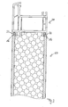
- a first embodiment of a frame assembly 10 is shown.
- the frame assembly comprises two parallel spaced plastic plates 12a and 12b. Between these two plastic plates 12a and 12b, an insulating layer 14 is arranged, so that the plastic plates 12a, 12b and the insulating layer 14 result in a sandwich plate.
- a connecting element 16 which is pin-shaped in cross section is provided, which is formed integrally with the corresponding plastic plate 12a, 12b.
- the connecting means 16 is a joining element of the first type for forming a snap connection with a joining element, not shown, of the second type.
- the joining element 16 has an undercut 18 and a snap hook 19. In the undercut 18, for example, a snap hook of a second joining element can be inserted. At the in Fig. 1 illustrated embodiment, a joining element of the first type 16 is provided on each end face.
- FIG. 2 shown frame connection element 100 differs from that in Fig. 1 shown frame connection element 10 characterized in that at one end face of a plastic plate 112a, 112b, a joining element of the first type 16 and on the opposite end face a joining element of the second type 20 are arranged. Both the joining element of the first type 16 and the wing element of the second type 20 are integrally formed with the plastic plates 112a and 112b.
- the joining element of the second type 20 comprises an undercut 22 and a snap hook 24. It is designed to form a snap connection with the joining element 16 of the first type.
- the joining element of the second type 20 is designed as an extension of the plastic plate 112a or 112b so that the outside of the joining element of the second type 20 and the outside of the plastic plate 112a or 112b forms a flat surface.
- the joining elements of the first type 16 and the second type 20 are essentially contoured and dimensioned such that when forming the snap connection between the joining element 16 of the first type 16 and the joining element of the second type 20, the outer sides of the plastic plates 112a and 112b to be joined form a flat surface.
- a joining element of the first type is arranged, is particularly suitable for use between two moldings of a window or door, as the moldings of two windows or doors usually a given shape exhibit. While the in Fig. 2 embodiment shown is particularly suitable to connect frame connection parts together.
- a frame connection element 10 is shown in conjunction with a profile strip 30 of a window or door frame.
- the profile strip has two joining elements of the second type 32, which form a snap connection with the joining elements of the first type 16 of the frame connection element 10.
- the plastic plate preferably has a thickness of about 3 to 6 mm.
- the illustrated joining elements of the first and second types 16, 20 and 32 are rail-like, in order to produce a stable connection between the two interconnected connection elements or between the connection element 10 and the profile strip 30.
Abstract
Description
Die vorliegende Erfindung betrifft ein Rahmenanschlusselement nach dem Oberbegriff des Anspruchs 1.The present invention relates to a frame connection element according to the preamble of claim 1.
Rahmenanschlusselemente finden beispielsweise Anwendung bei der Verbreiterung von Fenster- oder Türrahmen, um ein gegebenes Fenster oder eine gegebene Tür an eine vorgegebene Maueröffnung anzupassen. Hierbei werden die Rahmenanschlusselemente üblicherweise mit dem Profil eines Fensterrahmens verbunden. Ist die Maueröffnung im Vergleich zu einer einzubauenden Tür oder einem einzubauenden Fenster vergleichsweise groß, so kann die Notwendigkeit bestehen, dass mehrere Rahmenanschlusselemente miteinander verbunden werden müssen.Frame connection elements are used, for example, for widening window or door frames in order to adapt a given window or a given door to a predetermined wall opening. In this case, the frame connection elements are usually connected to the profile of a window frame. If the wall opening is comparatively large in comparison to a door to be installed or a window to be installed, there may be a need for several frame connection elements to be connected to one another.
Zum Verbinden der Rahmenanschlusselemente untereinander bzw. mit dem Profil eines Fenster- oder Türrahmens werden bisher beispielsweise Verbindungsklammern verwendet. Da diese Verbindungsklammer lösbar mit einem Rahmenanschlusselement verbunden ist, besteht die Gefahr, dass eine solche Verbindungsklammer verloren geht.To connect the frame connection elements with each other or with the profile of a window or door frame so far, for example, connection brackets are used. Since this connection clip is detachably connected to a frame connection element, there is a risk that such a connection clip is lost.
Weiterhin ist bekannt, eine Sandwichplatte mit einer Clipvorrichtung fest zu verbinden, die mit einer Clipvorrichtung eines Profils wechselwirkt. Dies hat den Nachteil, dass die Sandwichplatte mit einem zusätzlichen Element, nämlich dem Verbindungselement, fest verbunden, beispielsweise verklebt oder verschraubt, werden muss, was einen zusätzlichen unerwünschten Arbeitsschritt bedeutet.Furthermore, it is known to firmly connect a sandwich panel with a clip device that interacts with a clip device of a profile. This has the disadvantage that the sandwich panel with an additional element, namely the connecting element, firmly connected, for example glued or screwed, must be, which means an additional undesirable operation.
Es ist Aufgabe der vorliegenden Erfindung, ein Rahmenanschlusselement bereitzustellen, das auf einfache Weise mit einem weiteren Rahmenanschlusselement bzw. mit einer Profilleiste eines Fenster- oder Türrahmens verbindbar ist, und die oben genannten Nachteile überwindet.It is an object of the present invention to provide a frame connection element which can be connected in a simple manner to a further frame connection element or to a profile strip of a window or door frame, and overcomes the above-mentioned disadvantages.
Erfindungsgemäß wird diese Aufgabe bei einem Rahmenanschlusselement, umfassend eine Sandwichplatte mit zwei parallel im Abstand angeordneten Kunststoffplatten und einer Isolationsschicht, die zwischen den beiden im Abstand angeordneten Kunststoffplatten vorgesehen ist, und ein Verbindungsmittel dadurch gelöst, dass ein einstückig mit einer Kunststoffplatte ausgebildetes Verbindungsmittel an wenigstens einer Stirnseite wenigstens einer Kunststoffplatte vorgesehen ist und das Verbindungsmittel ein Fügeelement erster Art zur Ausbildung einer Schnappverbindung mit einem Fügeelement zweiter Art ist.According to the invention this object is achieved in a frame connection element comprising a sandwich plate with two parallel spaced plastic plates and an insulating layer which is provided between the two spaced plastic plates, and a connecting means in that an integrally formed with a plastic plate connecting means is provided on at least one end face of at least one plastic plate and the connecting means is a joining element of the first kind for forming a snap connection with a joining element of the second kind.
Auf diese Weise können zwei Rahmenanschlusselemente miteinander bzw. ein Rahmenanschlusselement mit einer Profilleiste einer Tür oder eines Fensters verbunden werden, ohne dass zusätzliche Elemente wie Klammern und dergleichen an der Sandwichplatte notwendig sind.In this way, two frame connection elements can be connected together or a frame connection element with a profile strip of a door or a window, without additional elements such as brackets and the like on the sandwich panel are necessary.
Bei einer bevorzugten Ausführungsform sind das Fügeelement erster Art und/oder das Fügeelement zweiter Art im Querschnitt stiftartig ausgebildet. Hierbei können beispielsweise das Fügeelement erster Art und das Fügeelement zweiter Art eine Hinterschneidung und einen Schnapphaken aufweisen.In a preferred embodiment, the joining element of the first type and / or the joining element of the second type are pin-shaped in cross-section. Here, for example, the joining element of the first type and the joining element of the second type may have an undercut and a snap hook.
Zur Ausbildung einer besonders stabilen Verbindung zwischen zwei Rahmenanschlusselementen bzw. zwischen einem Rahmenanschlusselement und einer Profilleiste ist es von Vorteil, dass das Fügeelement erster Art und/oder das Fügeelement zweiter Art schienenartig ausgebildet sind/ist.To form a particularly stable connection between two frame connection elements or between a frame connection element and a profile strip, it is advantageous that the joining element of the first type and / or the joining element of the second type are / is formed like a rail.
Weiterhin ist von Vorteil, dass das Fügeelement erster Art eine Verlängerung der inneren Seitenfläche der wenigstens einen Kunststoffplatte bildet. Auf diese Weise lässt sich das Fügeelement einfach, beispielsweise durch nachträgliches Fräsen an einer bereits gefertigten Sandwichplatte, herstellen.Furthermore, it is advantageous that the joining element of the first type forms an extension of the inner side surface of the at least one plastic plate. In this way, the joining element can be easily produced, for example by subsequent milling on an already manufactured sandwich panel.
Bei einer bevorzugten Ausführungsform ist an wenigstens einer Stirnseite der Sandwichplatte wenigstens abschnittsweise ein Abdeckelement, insbesondere ein Abdeckelement aus Kunststoff, vorgesehen. Das Abdeckelement dient dazu, beispielsweise die Isolationsschicht vor äußeren Einflüssen wie Feuchtigkeit oder Stößen zu schützen.In a preferred embodiment, a cover element, in particular a covering element made of plastic, is provided at least in sections on at least one end face of the sandwich panel. The cover serves to protect, for example, the insulation layer from external influences such as moisture or shock.
Zur Verbindung zweier Rahmenanschlusselemente miteinander ist es von Vorteil, dass die wenigstens eine Kunststoffplatte an einer Stirnseite ein Fügeelement erster Art und an der entgegengesetzt liegenden Stirnseite ein Fügeelement zweiter Art aufweist, wobei das Fügeelement zweiter Art einstückig mit der Kunststoffplatte ausgebildet ist.For connecting two frame connection elements to one another, it is advantageous that the at least one plastic plate has a joining element of the first type on one end side and a joining element of the second type on the opposite end side, wherein the joining element of the second type is formed integrally with the plastic plate.
Bei einer alternativen Ausführungsform weist die wenigstens eine Kunststoffplatte an beiden Stirnseiten jeweils ein Fügeelement erster Art auf. Diese Ausführungsform ist besonders für den Einsatz von einem Rahmenanschlusselement zwischen zwei Profilleisten eines Tür- oder Fensterrahmens geeignet.In an alternative embodiment, the at least one plastic plate has a joining element of the first type on both end faces. This embodiment is particularly suitable for the use of a frame connection element between two profile strips of a door or window frame.
Aus optischen Gründen ist es von Vorteil, dass bei zwei miteinander verbundenen Rahmenanschlusselementen bzw. bei einem mit einer Profilleiste verbundenen Rahmenanschlusselement die Außenseiten der beiden Rahmenanschlusselemente bzw. des Rahmenanschlusselements und der Profilleiste im Bereich der Schnappverbindung eine ebene Fläche ausbilden.For optical reasons, it is advantageous that in the case of two interconnected frame connection elements or in the case of a frame connection element connected to a profile strip, the outer sides of the two frame connection elements or the frame connection element and the profile strip form a flat surface in the region of the snap connection.
Bevorzugte Ausführungsformen werden anhand der beiliegenden Zeichnungen beschrieben, in denen zeigen:
- Fig. 1
- einen Querschnitt durch eine erste Ausführungsform eines Rahmenanschlusselements,
- Fig. 2
- einen Querschnitt durch eine zweite Ausführungsform eines Rahmenanschlusselements und
- Fig. 3
- einen Querschnitt eines mit einer Profilleiste verbundenen Rahmenanschlusselements.
- Fig. 1
- a cross section through a first embodiment of a frame connection element,
- Fig. 2
- a cross-section through a second embodiment of a frame connection element and
- Fig. 3
- a cross-section of a frame connecting element connected to a profile strip.
In
Das Verbindungsmittel 16 ist ein Fügeelement erster Art zur Ausbildung einer Schnappverbindung mit einem nicht dargestellten Fügeelement zweiter Art.The
Das Fügeelement 16 weist eine Hinterschneidung 18 und einen Schnapphaken 19 auf. In die Hinterschneidung 18 ist beispielsweise ein Schnapphaken eines zweiten Fügeelements einfügbar. Bei der in
Das in
Das Fügeelement zweiter Art 20 umfasst eine Hinterschneidung 22 und einen Schnapphaken 24. Es ist ausgelegt, um mit dem Fügeelement erster Art 16 eine Schnappverbindung auszubilden. Das Fügeelement zweiter Art 20 ist als Verlängerung der Kunststoffplatte 112a bzw. 112b so ausgebildet, dass die Außenseite des Fügeelements zweiter Art 20 und die Außenseite der Kunststoffplatte 112a bzw. 112b eine ebene Fläche ausbildet.The joining element of the
Die Fügeelemente erster Art 16 und zweiter Art 20 sind im Wesentlichen konturgleich und so dimensioniert, dass bei der Ausbildung der Schnappverbindung zwischen dem Fügeelement erster Art 16 und dem Fügeelement zweiter Art 20 die Außenseiten der zu verbindenden Kunststoffplatten 112a und 112b eine ebene Fläche ausbilden.The joining elements of the
Die in
In
Die Kunststoffplatte weist vorzugsweise eine Dicke von etwa 3 bis 6 mm auf. Wenn auch nicht in den Figuren erkennbar, so sind die dargestellten Fügeelemente erster und zweiter Art 16, 20 und 32 schienenartig ausgebildet, um eine stabile Verbindung zwischen den zwei miteinander verbundenen Anschlusselementen bzw. zwischen dem Anschlusselement 10 und der Profilleiste 30 herzustellen.The plastic plate preferably has a thickness of about 3 to 6 mm. Although not visible in the figures, the illustrated joining elements of the first and
Wenn die in
Claims (11)
dadurch gekennzeichnet, dass an wenigstens einer Stirnseite der Sandwichplatte wenigstens abschnittsweise ein Abdeckelement, insbesondere ein Abdeckelement aus Kunststoff, vorgesehen ist.Frame connection element according to one of the preceding claims,
characterized in that at least one end face of the sandwich panel at least partially a cover, in particular a cover made of plastic, is provided.
dadurch gekennzeichnet, dass die wenigstens eine Kunststoffplatte (112a, 112b) an einer Stirnseite ein Fügeelement erster Art (16) und an der entgegengesetzt liegenden Stirnseite ein Fügeelement zweiter Art (29) aufweist, wobei das Fügeelement zweiter Art (20) einstückig mit der Kunststoffplatte (112a, 112b) ausgebildet ist.Frame connection element according to one of the preceding claims,
characterized in that the at least one plastic plate (112a, 112b) on a front side a joining element of the first kind (16) and on the opposite end face a joining element of the second kind (29), wherein the joining element of the second type (20) integral with the plastic plate (112a, 112b) is formed.
Applications Claiming Priority (1)
| Application Number | Priority Date | Filing Date | Title |
|---|---|---|---|
| DE202011004097U DE202011004097U1 (en) | 2011-03-17 | 2011-03-17 | Frame arrangement with at least one frame connection element |
Publications (2)
| Publication Number | Publication Date |
|---|---|
| EP2500501A2 true EP2500501A2 (en) | 2012-09-19 |
| EP2500501A3 EP2500501A3 (en) | 2014-06-11 |
Family
ID=44586378
Family Applications (1)
| Application Number | Title | Priority Date | Filing Date |
|---|---|---|---|
| EP12001332.1A Withdrawn EP2500501A3 (en) | 2011-03-17 | 2012-02-29 | Frame assembly with at least one frame connection element |
Country Status (2)
| Country | Link |
|---|---|
| EP (1) | EP2500501A3 (en) |
| DE (1) | DE202011004097U1 (en) |
Families Citing this family (3)
| Publication number | Priority date | Publication date | Assignee | Title |
|---|---|---|---|---|
| AT13080U1 (en) * | 2012-01-11 | 2013-05-15 | Frinorm Ag | FRAME EXTENSION |
| DE202012001582U1 (en) | 2012-02-17 | 2012-04-17 | Sls Kunststoffverarbeitungs Gmbh & Co. Kg | Frame connection element |
| DE102021114500A1 (en) | 2021-06-07 | 2022-12-08 | Profine Gmbh | Two-part floor connection profile |
Family Cites Families (3)
| Publication number | Priority date | Publication date | Assignee | Title |
|---|---|---|---|---|
| US6314701B1 (en) * | 1998-02-09 | 2001-11-13 | Steven C. Meyerson | Construction panel and method |
| CH694435A5 (en) * | 2000-05-16 | 2005-01-14 | Dfs Technology & Service Ag | Frame extension for a window or door and window or door with this frame extension. |
| DE202010001398U1 (en) * | 2010-01-27 | 2010-05-27 | Beck, Walter, Dipl.-Ing. | profile system |
-
2011
- 2011-03-17 DE DE202011004097U patent/DE202011004097U1/en not_active Expired - Lifetime
-
2012
- 2012-02-29 EP EP12001332.1A patent/EP2500501A3/en not_active Withdrawn
Non-Patent Citations (1)
| Title |
|---|
| None |
Also Published As
| Publication number | Publication date |
|---|---|
| DE202011004097U1 (en) | 2011-08-08 |
| EP2500501A3 (en) | 2014-06-11 |
Similar Documents
| Publication | Publication Date | Title |
|---|---|---|
| EP1555376A1 (en) | Composite profile | |
| EP2581537B1 (en) | Window or door element | |
| DE102006059854A1 (en) | Reinforced plastic profile for window, door and façade elements | |
| DE202013103100U1 (en) | Surface element of a fire-resistant glazing, especially glass door for fire protection purposes to prevent the passage of fire and smoke in case of fire from one room to another | |
| EP2666948A1 (en) | Frame assembly for a panel for sectional doors | |
| EP2003280B1 (en) | Door leaf, ideally for a front door of a house | |
| DE102011120906A1 (en) | Fall protecting device for use in French balcony i.e. ground-deep window, for protecting person from fall, has plane element lying on securing lath to be arranged in use position of plane element on upper surface of plane element | |
| EP2500501A2 (en) | Frame assembly with at least one frame connection element | |
| EP2803807B1 (en) | Door | |
| DE202005007415U1 (en) | Window cross bar intended for the gap between two panes of an insulating window unit comprises two profile elements which are joined to one another before insertion into this gap | |
| EP2762668B1 (en) | Connection profile | |
| DE202016101078U1 (en) | railing | |
| DE202016101405U1 (en) | Box window for a building and box frame | |
| EP0775789A1 (en) | Building element of glass made of a multipane composite unit with an edge protection proceeding | |
| DE102008020988A1 (en) | Heat insulated frame profile for producing e.g. door frame, has hollow chamber formed at bar and at inner side of outer flat profile strip by side pieces for accommodating connecting elements | |
| EP1681430A2 (en) | Composite profile for frames of wall elements, doors and windows | |
| DE102013112435A1 (en) | Composite profile and method for producing a composite profile | |
| DE202013100101U1 (en) | Thermal insulation strip and frame profile for a window, a door, a facade or a light roof | |
| EP2593319B1 (en) | Window pane and method for mounting a window pane on a vehicle | |
| EP3574176B1 (en) | Guide rail for guiding roller shutters, sun screens or similar, and a method for its manufacturing | |
| AT513757B1 (en) | connection profile | |
| DE102011008765A1 (en) | Profile arrangement for frame, particularly for door- or window frame or door- or window sash, of frame arrangement, has two profiles, where former profile is aluminum profile and latter profile is plastic profile | |
| CH704434B1 (en) | Plate-shaped insulating element for frame extension of header joists of window or door frame in building, has connecting element having cross-section and head and neck portions, where head portion is partially rounded | |
| DE102014112092A1 (en) | Door, window or façade element with a corner connector | |
| DE102017108587A1 (en) | Composite window and combination glass holder for this |
Legal Events
| Date | Code | Title | Description |
|---|---|---|---|
| PUAI | Public reference made under article 153(3) epc to a published international application that has entered the european phase |
Free format text: ORIGINAL CODE: 0009012 |
|
| AK | Designated contracting states |
Kind code of ref document: A2 Designated state(s): AL AT BE BG CH CY CZ DE DK EE ES FI FR GB GR HR HU IE IS IT LI LT LU LV MC MK MT NL NO PL PT RO RS SE SI SK SM TR |
|
| AX | Request for extension of the european patent |
Extension state: BA ME |
|
| PUAL | Search report despatched |
Free format text: ORIGINAL CODE: 0009013 |
|
| AK | Designated contracting states |
Kind code of ref document: A3 Designated state(s): AL AT BE BG CH CY CZ DE DK EE ES FI FR GB GR HR HU IE IS IT LI LT LU LV MC MK MT NL NO PL PT RO RS SE SI SK SM TR |
|
| AX | Request for extension of the european patent |
Extension state: BA ME |
|
| RIC1 | Information provided on ipc code assigned before grant |
Ipc: E06B 1/02 20060101ALI20140508BHEP Ipc: E06B 1/62 20060101AFI20140508BHEP |
|
| STAA | Information on the status of an ep patent application or granted ep patent |
Free format text: STATUS: THE APPLICATION IS DEEMED TO BE WITHDRAWN |
|
| 18D | Application deemed to be withdrawn |
Effective date: 20141212 |