EP2500271A2 - Drahtloses Stromübertragungssystem und Verfahren für ein Flugzeugsensorsystem - Google Patents
Drahtloses Stromübertragungssystem und Verfahren für ein Flugzeugsensorsystem Download PDFInfo
- Publication number
- EP2500271A2 EP2500271A2 EP12250052A EP12250052A EP2500271A2 EP 2500271 A2 EP2500271 A2 EP 2500271A2 EP 12250052 A EP12250052 A EP 12250052A EP 12250052 A EP12250052 A EP 12250052A EP 2500271 A2 EP2500271 A2 EP 2500271A2
- Authority
- EP
- European Patent Office
- Prior art keywords
- module
- aircraft
- sensor
- operative
- electrical power
- Prior art date
- Legal status (The legal status is an assumption and is not a legal conclusion. Google has not performed a legal analysis and makes no representation as to the accuracy of the status listed.)
- Granted
Links
Images

Classifications
-
- B—PERFORMING OPERATIONS; TRANSPORTING
- B64—AIRCRAFT; AVIATION; COSMONAUTICS
- B64D—EQUIPMENT FOR FITTING IN OR TO AIRCRAFT; FLIGHT SUITS; PARACHUTES; ARRANGEMENT OR MOUNTING OF POWER PLANTS OR PROPULSION TRANSMISSIONS IN AIRCRAFT
- B64D45/00—Aircraft indicators or protectors not otherwise provided for
- B64D45/0005—Devices specially adapted to indicate the position of a movable element of the aircraft, e.g. landing gear
-
- H—ELECTRICITY
- H02—GENERATION; CONVERSION OR DISTRIBUTION OF ELECTRIC POWER
- H02J—CIRCUIT ARRANGEMENTS OR SYSTEMS FOR SUPPLYING OR DISTRIBUTING ELECTRIC POWER; SYSTEMS FOR STORING ELECTRIC ENERGY
- H02J50/00—Circuit arrangements or systems for wireless supply or distribution of electric power
- H02J50/10—Circuit arrangements or systems for wireless supply or distribution of electric power using inductive coupling
- H02J50/12—Circuit arrangements or systems for wireless supply or distribution of electric power using inductive coupling of the resonant type
-
- H—ELECTRICITY
- H02—GENERATION; CONVERSION OR DISTRIBUTION OF ELECTRIC POWER
- H02J—CIRCUIT ARRANGEMENTS OR SYSTEMS FOR SUPPLYING OR DISTRIBUTING ELECTRIC POWER; SYSTEMS FOR STORING ELECTRIC ENERGY
- H02J50/00—Circuit arrangements or systems for wireless supply or distribution of electric power
- H02J50/80—Circuit arrangements or systems for wireless supply or distribution of electric power involving the exchange of data, concerning supply or distribution of electric power, between transmitting devices and receiving devices
-
- H02J7/42—
-
- H02J2105/32—
Definitions
- the present invention generally relates to a sensor system for use with an aircraft. More particularly, the present invention relates to an aircraft sensor system for use with a landing gear assembly which wirelessly receives electrical power for operation thereoF
- landing gear moves between a deployed (landing) position and a retracted (flying) position. As the landing gear is retracted and deployed during flight, it is important to create as little drag as possible.
- An aircraft sensor system in which an aspect of the invention, in accordance with the illustrated embodiments, includes a primary module configured to be attached to an aircraft portion, such as a portion of the aircraft landing bay.
- the primary module is operative to transmit electrical power wirelessly and may also be operative to receive data wirelessly.
- a secondary module is provided which is configured to be attached to an aircraft component, such as a landing gear assembly.
- the secondary module being operative to receive and optionally store electrical power wirelessly from the primary module and optionally transmit data wirelessly to the primary module.
- at least one sensor configured to be operatively attached to a portion of the aircraft component and electrically coupled to the secondary module.
- the at least one sensor may receive operating electrical power from the secondary module and is operative to measure a parameter, for example an operating parameter, of the aircraft component and optionally to provide corresponding data to the secondary module.
- the primary module and secondary module may be operative to transfer electrical power wirelessly by inductive coupling.
- the primary module and secondary module may be operative to transfer electrical power wirelessly by resonant inductive coupling.
- the aircraft component may be a retractable landing gear assembly.
- the primary module may be configured to be mounted in close proximity to the secondary module.
- the aircraft sensor system may further include a power storage module configured to be mounted in close proximity to the aircraft component and being electrically coupled to the at least one sensor, the power storage module operative to provide electrical power to the at least one sensor.
- the power storage module may include at least one rechargeable battery configured to store electrical power.
- the power storage module may include at least one capacitor configured to store electrical power,
- the power storage module may be configured to provide electrical power to the at least one sensor during periods when the secondary module is not receiving electrical power from the primary module.
- the secondary module may be configured to charge the power storage module with electrical power received from the primary module.
- an aircraft sensor system comprising: a primary module configured to be attached to an aircraft portion, the primary module operative to transmit electrical power wirelessly and operative to receive data wirelessly; a secondary module configured to be attached to an aircraft component, the secondary module operative to receive electrical power wirelessly from the primary module and transmit data wirelessly to the primary module; and at least one sensor configured to be operatively attached to a portion of the aircraft component and electrically coupled to the secondary module, wherein the at least one sensor is operative to measure a desired parameter of the aircraft component and provide corresponding data to the secondary module.
- the primary module and secondary module may be operative to transfer electrical power wirelessly by inductive coupling.
- the primary module and secondary module may be operative to transfer electrical power wirelessly by resonant inductive coupling.
- the primary module may be operative to transmit data wirelessly and the secondary module is operative to receive data wirelessly.
- the aircraft component may be a retractable landing gear assembly.
- the primary module may be configured to be mounted proximal to the secondary module.
- the aircraft sensor system may further include a power storage module configured to be mounted proximal to the aircraft component and being electrically coupled to the at least one sensor, the power storage module operative to provide electrical power to the at least one sensor.
- the power storage module may include at least one rechargeable battery configured to store electrical power.
- the power storage module may include at least one capacitor configured to store electrical power.
- the power storage module may be configured to provide electrical power to the at least one sensor during periods when the secondary module is not receiving electrical power from the primary module.
- the secondary module may be configured to charge the power storage module with electrical power received from the primary module.
- a method of operating a retractable landing gear sensor system comprising: transmitting power wirelessly from a primary module attached to a portion of a retractable landing gear assembly; receiving power wirelessly by a secondary module attached to a portion of the retractable landing gear assembly; powering at least one sensor attached to the retractable landing gear from wireless power received from the primary module; measuring at least one desired parameter of the retractable landing gear by the at least one sensor; and collecting measurement data by the secondary module from the at least one sensor.
- the method may further include a step of transmitting the measurement data wirelessly from the secondary module to the primary module.
- the method may further include a steps of: providing a power storage module electrically coupled to the at least one sensor and the secondary module; and charging the power storage module from power wirelessly received by the secondary module.
- the present invention in accordance with the illustrated embodiments, is directed to a system and method for enabling wireless data and power transmission between a fuselage portion of an aircraft and an aircraft component, such as an aircraft landing gear assembly.
- the present invention is to be understood to be implemented in conjunction with the landing gear assembly 10 of an aircraft 100.
- the present invention is not to be understood to be limited for use with an aircraft landing assembly as it may be used in conjunction with any component of the aircraft benefiting from its functionality.
- Figs. 1 and 2 while the invention is illustrated for use with the front landing assembly 10 of aircraft 12, it is to be understood it may be implemented with the rear landing gear assemblies 14, 16, and any combination thereof.
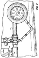
- the landing gear assembly 10 is configured and operable to extend outwardly and retract inwardly relative to a landing gear bay 18 8 defined in the fuselage 20 of an aircraft 12.
- Landing gear assembly 10 is understood to include a plurality of powered sensor devices 310, 312 each configured to measure performance parameters associated with the landing gear assembly 10,
- the powered sensor devices 310, 312 are to be understood to be located within the secondary module 300 affixed through any conventional means (e.g., screw assemblies, rivets, weld, glue and other like affixation means) to the landing gear assembly 10.
- the secondary module 300 is mounted in close proximity to the movable components of the landing gear assembly 10 when retracted outwardly from the landing gear bay 18.
- the powered sensor devices 310, 312 are not to be understood to be limited to inclusion in to aforesaid secondary module 300, as it is to be understood, one or more of the powered sensors 310, 312 may be located external of the secondary module 300 with electrical power connection thereto.
- Such powered sensor devices 310, 312 may include (but are not to be understood to be limited thereto): load sensors, brake and wheel motion sensors, tire pressure sensors, weight on wheel sensors and gear lock sensors. As mentioned above, and as further discussed below, each powered sensor device system 310, 312 typically requires connection to an electrical power source for operation thereof to measure and typically stores prescribed data. As is typical, each powered sensor device 310, 312 is coupled to an aircraft control system 200 for relaying determined and prescribed data from each sensor device system 310, 312 to the aircraft control system 200, which controls and monitors operation of the aircraft 12 thereof.
- a primary fixed module 350 is preferably affixed within the landing gear bay 1$ through any conventional means (e.g., screw assemblies, rivets, weld, glue and other like affixation means).
- the primary module 350 is mounted in close proximity to the movable components (and preferably the secondary module 300) of the landing gear assembly 10 when retracted within the landing gear bay 18 of aircraft 10, as shown in FIG. 3 .
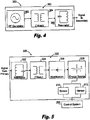
- each primary 350 and secondary 300 module respectively includes inductive circuitry 360, 320.
- the inductive circuitry 360, 320 of primary 350 and secondary 300 modules are configured such that, using electrical inductive principles, electrical power is inductively transferred from the inductive circuitry 360 of the primary module 350 to the inductive circuitry 320 of the secondary module 320, such that electrical powered is stored for use with the aforesaid sensor device systems 310, 312, as also further discussed below.
- the two conductors of the inductive circuitry 360, 320 are commonly referred to as mutual-inductively coupled or magnetically coupled and they are configured such that a change in current flow through one of the conductors induces a voltage across the ends of the other conductor through electromagnetic induction.
- the amount of inductive coupling between two conductors of the inductive circuitry 360, 320 is typically determined by their mutual inductance. Additionally, it is to be understood the coupling between wires of the inductive circuits 360, 320 can be increased by winding them into coils and placing them close together on a common axis, so the magnetic field of one coil passes through the other coil.
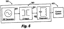
- the inductive circuitry 360 of the primary module 350 preferably includes an RF generator 362 coupled to a Z-Match circuit 364 coupled to a primary resonator coil 366.
- the inductive circuitry 320 of the secondary module 300 includes a secondary resonator coil 322 coupled to a Z-match circuit 324 which in turn is coupled to a rectifying circuit 326 coupled to a energy store device 328.
- the energy storage device 328 can be a multitude of devices capable of storing electrical energy, such as a rechargeable battery or capacitor.
- the energy storage device 328 is coupled to each aforesaid sensor device system 310, 312 for providing electrical energy to power each sensor device system 310, 312.
- electrical power is transferred from the primary module, 350 to the secondary module 300, via primary 366 and secondary 322 inductor coils, so as to be stored in the rechargeable energy source 328 for use by each sensor device system 310, 312.
- each sensor device system 310,312 when the landing gear assembly 10 is caused to be moved to its extended position, each sensor device system 310,312 preferably becomes activated to sense and record prescribed data relating to the landing gear assembly 10.
- the electrical power for energizing each sensor device system 310, 312 is respectively provided from the rechargeable energy source 328 of the secondary module 300.
- the primary 330 and secondary 300 modules are configured such that data which is collected by each sensor device system 310, 312 may communicate it's data to the control system 400 of aircraft 12 by a radio link using the inductive coupling between then primary 366 and secondary 322 inductor coils of the respective primary 350 and secondary 300 modules as the wireless transmission means.
- the radio signals are received in the primary module 350 from the sensor device systems 310, 312, they are provided to the aircraft control system 400 coupled thereto.
- each sensor device system 310, 312 and the aircraft control system 400 may occur whether the landing gear assembly 10 is retracted within the landing gear bay 18 of the aircraft 10 ( FIG. 3 ) or extending outwardly therefrom ( FIG. 2 ).
Landscapes
- Engineering & Computer Science (AREA)
- Computer Networks & Wireless Communication (AREA)
- Power Engineering (AREA)
- Aviation & Aerospace Engineering (AREA)
- Arrangements For Transmission Of Measured Signals (AREA)
Applications Claiming Priority (1)
| Application Number | Priority Date | Filing Date | Title |
|---|---|---|---|
| US13/047,493 US8686590B2 (en) | 2011-03-14 | 2011-03-14 | Wireless power transmission system and method for an aircraft sensor system |
Publications (3)
| Publication Number | Publication Date |
|---|---|
| EP2500271A2 true EP2500271A2 (de) | 2012-09-19 |
| EP2500271A3 EP2500271A3 (de) | 2015-07-15 |
| EP2500271B1 EP2500271B1 (de) | 2017-05-03 |
Family
ID=45977302
Family Applications (1)
| Application Number | Title | Priority Date | Filing Date |
|---|---|---|---|
| EP12250052.3A Not-in-force EP2500271B1 (de) | 2011-03-14 | 2012-03-09 | Drahtloses Stromübertragungssystem und Verfahren für ein Flugzeugsensorsystem |
Country Status (2)
| Country | Link |
|---|---|
| US (1) | US8686590B2 (de) |
| EP (1) | EP2500271B1 (de) |
Cited By (1)
| Publication number | Priority date | Publication date | Assignee | Title |
|---|---|---|---|---|
| WO2013107844A1 (en) * | 2012-01-19 | 2013-07-25 | Airbus Operations Gmbh | Wireless network having a local electrical power supply in aircraft |
Families Citing this family (16)
| Publication number | Priority date | Publication date | Assignee | Title |
|---|---|---|---|---|
| US8918418B2 (en) | 2010-04-19 | 2014-12-23 | Facebook, Inc. | Default structured search queries on online social networks |
| US8180804B1 (en) | 2010-04-19 | 2012-05-15 | Facebook, Inc. | Dynamically generating recommendations based on social graph information |
| US8185558B1 (en) | 2010-04-19 | 2012-05-22 | Facebook, Inc. | Automatically generating nodes and edges in an integrated social graph |
| US8732208B2 (en) | 2010-04-19 | 2014-05-20 | Facebook, Inc. | Structured search queries based on social-graph information |
| US8751521B2 (en) | 2010-04-19 | 2014-06-10 | Facebook, Inc. | Personalized structured search queries for online social networks |
| US8782080B2 (en) | 2010-04-19 | 2014-07-15 | Facebook, Inc. | Detecting social graph elements for structured search queries |
| US8868603B2 (en) | 2010-04-19 | 2014-10-21 | Facebook, Inc. | Ambiguous structured search queries on online social networks |
| US8841881B2 (en) | 2010-06-02 | 2014-09-23 | Bryan Marc Failing | Energy transfer with vehicles |
| ES2504915B2 (es) * | 2013-04-04 | 2015-03-24 | Santiago RUANO RUEDA | Sistema de seguridad para aeronaves |
| US20160072179A1 (en) * | 2013-04-12 | 2016-03-10 | Sikorsky Aircraft Corporation | Hollow composite structure used as waveguide |
| FR3013681B1 (fr) * | 2013-11-22 | 2017-06-09 | Messier Bugatti Dowty | Procede pour diminuer le temps de manoeuvre apparent d'atterrisseurs d'un aeronef. |
| US10377469B2 (en) * | 2016-03-04 | 2019-08-13 | The Boeing Company | Non-contact power supply and data transfer on aerial vehicles |
| CN106081106B (zh) * | 2016-06-17 | 2021-02-05 | 深圳市元征科技股份有限公司 | 无线充电无人机 |
| FR3099723B1 (fr) * | 2019-08-05 | 2021-11-12 | Safran Landing Systems | Procédé de gestion d’énergie d’un système de vérification de la pression de gonflage des pneumatiques d’un aéronef |
| US11476712B2 (en) * | 2021-02-01 | 2022-10-18 | Nucurrent, Inc. | Wirelessly powered sensor system |
| US20230037429A1 (en) * | 2021-08-03 | 2023-02-09 | Powermat Technologies Ltd. | Wireless power receiver design for drones |
Citations (1)
| Publication number | Priority date | Publication date | Assignee | Title |
|---|---|---|---|---|
| US5908174A (en) | 1996-10-31 | 1999-06-01 | Coltec Industries Inc. | Automatic shrink shock strut for an aircraft landing gear |
Family Cites Families (6)
| Publication number | Priority date | Publication date | Assignee | Title |
|---|---|---|---|---|
| US7490793B2 (en) * | 2002-10-18 | 2009-02-17 | The Boeing Company | Wireless landing gear monitoring system |
| US7276703B2 (en) * | 2005-11-23 | 2007-10-02 | Lockheed Martin Corporation | System to monitor the health of a structure, sensor nodes, program product, and related methods |
| US20080033607A1 (en) * | 2006-06-01 | 2008-02-07 | Bob Zeliff | Monitoring system for aircraft landing system |
| US8026857B2 (en) * | 2008-01-17 | 2011-09-27 | The Boeing Company | Wireless data communication and power transmission using aircraft structures having properties of an electromagnetic cavity |
| US8878393B2 (en) * | 2008-05-13 | 2014-11-04 | Qualcomm Incorporated | Wireless power transfer for vehicles |
| DE102009009189B4 (de) * | 2009-02-16 | 2011-06-16 | Airbus Operations Gmbh | Sensor und Sensornetzwerk für ein Luftfahrzeug |
-
2011
- 2011-03-14 US US13/047,493 patent/US8686590B2/en not_active Expired - Fee Related
-
2012
- 2012-03-09 EP EP12250052.3A patent/EP2500271B1/de not_active Not-in-force
Patent Citations (1)
| Publication number | Priority date | Publication date | Assignee | Title |
|---|---|---|---|---|
| US5908174A (en) | 1996-10-31 | 1999-06-01 | Coltec Industries Inc. | Automatic shrink shock strut for an aircraft landing gear |
Cited By (2)
| Publication number | Priority date | Publication date | Assignee | Title |
|---|---|---|---|---|
| WO2013107844A1 (en) * | 2012-01-19 | 2013-07-25 | Airbus Operations Gmbh | Wireless network having a local electrical power supply in aircraft |
| US10035476B2 (en) | 2012-01-19 | 2018-07-31 | Airbus Operations Gmbh | Wireless network having a local electrical power supply in aircraft |
Also Published As
| Publication number | Publication date |
|---|---|
| EP2500271A3 (de) | 2015-07-15 |
| US8686590B2 (en) | 2014-04-01 |
| US20120234971A1 (en) | 2012-09-20 |
| EP2500271B1 (de) | 2017-05-03 |
Similar Documents
| Publication | Publication Date | Title |
|---|---|---|
| EP2500271B1 (de) | Drahtloses Stromübertragungssystem und Verfahren für ein Flugzeugsensorsystem | |
| KR101438298B1 (ko) | 비접촉 급전 장치 및 비접촉 급전 방법 | |
| US10673282B2 (en) | Tunable wireless energy transfer systems | |
| US10099561B1 (en) | Airborne unmanned aerial vehicle charging | |
| EP3036820B1 (de) | Systeme und verfahren zur bi-zustandsimpedanzumwandlung bei drahtlosem stromtransfer | |
| US20130020878A1 (en) | Wireless power component selection | |
| US9444247B2 (en) | Apparatus and method of protecting power receiver of wireless power transmission system | |
| US20180290545A1 (en) | On-board and wireless vehicle charging systems with shared components | |
| JP5654120B2 (ja) | 適応無線エネルギー伝送システム | |
| US9376026B2 (en) | System and method for inductance compensation in wireless power transfer | |
| Krishnan et al. | Frequency agile resonance-based wireless charging system for electric vehicles | |
| US20130038282A1 (en) | Power reception apparatus and power receiving method | |
| JP6977654B2 (ja) | ワイヤレス受電装置、及びワイヤレス電力伝送システム | |
| JP2017135880A (ja) | 無線給電システム | |
| JP2011147213A (ja) | 電力伝送システムおよび車両用給電装置 | |
| EP3038232B1 (de) | Steuerungsverfahren und -vorrichtung für drahtloses stromübertragungssystem einer motorvorrichtung | |
| EP2787595B1 (de) | Kontaktlose Kommunikationsspule, kontaktlose Stromversorgungsvorrichtung, und kontaktlose Stromversorgungsempfangsvorrichtung | |
| EP3104497B1 (de) | Kontaktloses energieversorgungssystem | |
| EP2728711A1 (de) | Verfahren zum entwurf eines stromversorgungssystems und stromversorgungssystem | |
| EP3046219A1 (de) | Drahtlose stromempfangsvorrichtung | |
| CN115703372A (zh) | 无人机的无线电源接收器设计 | |
| KR20170058519A (ko) | 무인항공 택배방법 및 시스템 | |
| JP2014155278A (ja) | 変換ユニット | |
| CN109435712A (zh) | 无人机无线充电的磁耦合结构及系统 | |
| KR20170053966A (ko) | 3상 교류 전력 무선 전달 시스템 및 이를 이용한 3상 무선 충전형 무인 비행체 |
Legal Events
| Date | Code | Title | Description |
|---|---|---|---|
| PUAI | Public reference made under article 153(3) epc to a published international application that has entered the european phase |
Free format text: ORIGINAL CODE: 0009012 |
|
| 17P | Request for examination filed |
Effective date: 20120322 |
|
| AK | Designated contracting states |
Kind code of ref document: A2 Designated state(s): AL AT BE BG CH CY CZ DE DK EE ES FI FR GB GR HR HU IE IS IT LI LT LU LV MC MK MT NL NO PL PT RO RS SE SI SK SM TR |
|
| AX | Request for extension of the european patent |
Extension state: BA ME |
|
| PUAL | Search report despatched |
Free format text: ORIGINAL CODE: 0009013 |
|
| AK | Designated contracting states |
Kind code of ref document: A3 Designated state(s): AL AT BE BG CH CY CZ DE DK EE ES FI FR GB GR HR HU IE IS IT LI LT LU LV MC MK MT NL NO PL PT RO RS SE SI SK SM TR |
|
| AX | Request for extension of the european patent |
Extension state: BA ME |
|
| RIC1 | Information provided on ipc code assigned before grant |
Ipc: H02J 7/02 20060101ALI20150610BHEP Ipc: B64D 45/00 20060101AFI20150610BHEP |
|
| RIC1 | Information provided on ipc code assigned before grant |
Ipc: H02J 7/02 20060101ALI20160929BHEP Ipc: B64D 45/00 20060101AFI20160929BHEP |
|
| GRAP | Despatch of communication of intention to grant a patent |
Free format text: ORIGINAL CODE: EPIDOSNIGR1 |
|
| INTG | Intention to grant announced |
Effective date: 20161110 |
|
| GRAS | Grant fee paid |
Free format text: ORIGINAL CODE: EPIDOSNIGR3 |
|
| GRAA | (expected) grant |
Free format text: ORIGINAL CODE: 0009210 |
|
| AK | Designated contracting states |
Kind code of ref document: B1 Designated state(s): AL AT BE BG CH CY CZ DE DK EE ES FI FR GB GR HR HU IE IS IT LI LT LU LV MC MK MT NL NO PL PT RO RS SE SI SK SM TR |
|
| REG | Reference to a national code |
Ref country code: GB Ref legal event code: FG4D |
|
| REG | Reference to a national code |
Ref country code: AT Ref legal event code: REF Ref document number: 889672 Country of ref document: AT Kind code of ref document: T Effective date: 20170515 Ref country code: CH Ref legal event code: EP |
|
| REG | Reference to a national code |
Ref country code: IE Ref legal event code: FG4D |
|
| REG | Reference to a national code |
Ref country code: DE Ref legal event code: R096 Ref document number: 602012031863 Country of ref document: DE |
|
| REG | Reference to a national code |
Ref country code: NL Ref legal event code: MP Effective date: 20170503 |
|
| REG | Reference to a national code |
Ref country code: AT Ref legal event code: MK05 Ref document number: 889672 Country of ref document: AT Kind code of ref document: T Effective date: 20170503 |
|
| REG | Reference to a national code |
Ref country code: LT Ref legal event code: MG4D |
|
| PG25 | Lapsed in a contracting state [announced via postgrant information from national office to epo] |
Ref country code: HR Free format text: LAPSE BECAUSE OF FAILURE TO SUBMIT A TRANSLATION OF THE DESCRIPTION OR TO PAY THE FEE WITHIN THE PRESCRIBED TIME-LIMIT Effective date: 20170503 Ref country code: GR Free format text: LAPSE BECAUSE OF FAILURE TO SUBMIT A TRANSLATION OF THE DESCRIPTION OR TO PAY THE FEE WITHIN THE PRESCRIBED TIME-LIMIT Effective date: 20170804 Ref country code: NO Free format text: LAPSE BECAUSE OF FAILURE TO SUBMIT A TRANSLATION OF THE DESCRIPTION OR TO PAY THE FEE WITHIN THE PRESCRIBED TIME-LIMIT Effective date: 20170803 Ref country code: ES Free format text: LAPSE BECAUSE OF FAILURE TO SUBMIT A TRANSLATION OF THE DESCRIPTION OR TO PAY THE FEE WITHIN THE PRESCRIBED TIME-LIMIT Effective date: 20170503 Ref country code: AT Free format text: LAPSE BECAUSE OF FAILURE TO SUBMIT A TRANSLATION OF THE DESCRIPTION OR TO PAY THE FEE WITHIN THE PRESCRIBED TIME-LIMIT Effective date: 20170503 Ref country code: FI Free format text: LAPSE BECAUSE OF FAILURE TO SUBMIT A TRANSLATION OF THE DESCRIPTION OR TO PAY THE FEE WITHIN THE PRESCRIBED TIME-LIMIT Effective date: 20170503 Ref country code: LT Free format text: LAPSE BECAUSE OF FAILURE TO SUBMIT A TRANSLATION OF THE DESCRIPTION OR TO PAY THE FEE WITHIN THE PRESCRIBED TIME-LIMIT Effective date: 20170503 |
|
| PG25 | Lapsed in a contracting state [announced via postgrant information from national office to epo] |
Ref country code: NL Free format text: LAPSE BECAUSE OF FAILURE TO SUBMIT A TRANSLATION OF THE DESCRIPTION OR TO PAY THE FEE WITHIN THE PRESCRIBED TIME-LIMIT Effective date: 20170503 Ref country code: BG Free format text: LAPSE BECAUSE OF FAILURE TO SUBMIT A TRANSLATION OF THE DESCRIPTION OR TO PAY THE FEE WITHIN THE PRESCRIBED TIME-LIMIT Effective date: 20170803 Ref country code: IS Free format text: LAPSE BECAUSE OF FAILURE TO SUBMIT A TRANSLATION OF THE DESCRIPTION OR TO PAY THE FEE WITHIN THE PRESCRIBED TIME-LIMIT Effective date: 20170903 Ref country code: LV Free format text: LAPSE BECAUSE OF FAILURE TO SUBMIT A TRANSLATION OF THE DESCRIPTION OR TO PAY THE FEE WITHIN THE PRESCRIBED TIME-LIMIT Effective date: 20170503 Ref country code: SE Free format text: LAPSE BECAUSE OF FAILURE TO SUBMIT A TRANSLATION OF THE DESCRIPTION OR TO PAY THE FEE WITHIN THE PRESCRIBED TIME-LIMIT Effective date: 20170503 Ref country code: PL Free format text: LAPSE BECAUSE OF FAILURE TO SUBMIT A TRANSLATION OF THE DESCRIPTION OR TO PAY THE FEE WITHIN THE PRESCRIBED TIME-LIMIT Effective date: 20170503 Ref country code: RS Free format text: LAPSE BECAUSE OF FAILURE TO SUBMIT A TRANSLATION OF THE DESCRIPTION OR TO PAY THE FEE WITHIN THE PRESCRIBED TIME-LIMIT Effective date: 20170503 |
|
| PG25 | Lapsed in a contracting state [announced via postgrant information from national office to epo] |
Ref country code: EE Free format text: LAPSE BECAUSE OF FAILURE TO SUBMIT A TRANSLATION OF THE DESCRIPTION OR TO PAY THE FEE WITHIN THE PRESCRIBED TIME-LIMIT Effective date: 20170503 Ref country code: DK Free format text: LAPSE BECAUSE OF FAILURE TO SUBMIT A TRANSLATION OF THE DESCRIPTION OR TO PAY THE FEE WITHIN THE PRESCRIBED TIME-LIMIT Effective date: 20170503 Ref country code: CZ Free format text: LAPSE BECAUSE OF FAILURE TO SUBMIT A TRANSLATION OF THE DESCRIPTION OR TO PAY THE FEE WITHIN THE PRESCRIBED TIME-LIMIT Effective date: 20170503 Ref country code: RO Free format text: LAPSE BECAUSE OF FAILURE TO SUBMIT A TRANSLATION OF THE DESCRIPTION OR TO PAY THE FEE WITHIN THE PRESCRIBED TIME-LIMIT Effective date: 20170503 Ref country code: SK Free format text: LAPSE BECAUSE OF FAILURE TO SUBMIT A TRANSLATION OF THE DESCRIPTION OR TO PAY THE FEE WITHIN THE PRESCRIBED TIME-LIMIT Effective date: 20170503 |
|
| REG | Reference to a national code |
Ref country code: DE Ref legal event code: R097 Ref document number: 602012031863 Country of ref document: DE |
|
| REG | Reference to a national code |
Ref country code: FR Ref legal event code: PLFP Year of fee payment: 7 |
|
| PG25 | Lapsed in a contracting state [announced via postgrant information from national office to epo] |
Ref country code: SM Free format text: LAPSE BECAUSE OF FAILURE TO SUBMIT A TRANSLATION OF THE DESCRIPTION OR TO PAY THE FEE WITHIN THE PRESCRIBED TIME-LIMIT Effective date: 20170503 |
|
| PLBE | No opposition filed within time limit |
Free format text: ORIGINAL CODE: 0009261 |
|
| STAA | Information on the status of an ep patent application or granted ep patent |
Free format text: STATUS: NO OPPOSITION FILED WITHIN TIME LIMIT |
|
| 26N | No opposition filed |
Effective date: 20180206 |
|
| PG25 | Lapsed in a contracting state [announced via postgrant information from national office to epo] |
Ref country code: SI Free format text: LAPSE BECAUSE OF FAILURE TO SUBMIT A TRANSLATION OF THE DESCRIPTION OR TO PAY THE FEE WITHIN THE PRESCRIBED TIME-LIMIT Effective date: 20170503 |
|
| REG | Reference to a national code |
Ref country code: CH Ref legal event code: PL |
|
| PG25 | Lapsed in a contracting state [announced via postgrant information from national office to epo] |
Ref country code: MC Free format text: LAPSE BECAUSE OF FAILURE TO SUBMIT A TRANSLATION OF THE DESCRIPTION OR TO PAY THE FEE WITHIN THE PRESCRIBED TIME-LIMIT Effective date: 20170503 |
|
| REG | Reference to a national code |
Ref country code: BE Ref legal event code: MM Effective date: 20180331 |
|
| REG | Reference to a national code |
Ref country code: IE Ref legal event code: MM4A |
|
| PG25 | Lapsed in a contracting state [announced via postgrant information from national office to epo] |
Ref country code: LU Free format text: LAPSE BECAUSE OF NON-PAYMENT OF DUE FEES Effective date: 20180309 |
|
| PG25 | Lapsed in a contracting state [announced via postgrant information from national office to epo] |
Ref country code: IE Free format text: LAPSE BECAUSE OF NON-PAYMENT OF DUE FEES Effective date: 20180309 |
|
| PG25 | Lapsed in a contracting state [announced via postgrant information from national office to epo] |
Ref country code: BE Free format text: LAPSE BECAUSE OF NON-PAYMENT OF DUE FEES Effective date: 20180331 Ref country code: LI Free format text: LAPSE BECAUSE OF NON-PAYMENT OF DUE FEES Effective date: 20180331 Ref country code: CH Free format text: LAPSE BECAUSE OF NON-PAYMENT OF DUE FEES Effective date: 20180331 |
|
| PG25 | Lapsed in a contracting state [announced via postgrant information from national office to epo] |
Ref country code: MT Free format text: LAPSE BECAUSE OF NON-PAYMENT OF DUE FEES Effective date: 20180309 |
|
| PG25 | Lapsed in a contracting state [announced via postgrant information from national office to epo] |
Ref country code: TR Free format text: LAPSE BECAUSE OF FAILURE TO SUBMIT A TRANSLATION OF THE DESCRIPTION OR TO PAY THE FEE WITHIN THE PRESCRIBED TIME-LIMIT Effective date: 20170503 |
|
| PG25 | Lapsed in a contracting state [announced via postgrant information from national office to epo] |
Ref country code: HU Free format text: LAPSE BECAUSE OF FAILURE TO SUBMIT A TRANSLATION OF THE DESCRIPTION OR TO PAY THE FEE WITHIN THE PRESCRIBED TIME-LIMIT; INVALID AB INITIO Effective date: 20120309 Ref country code: PT Free format text: LAPSE BECAUSE OF FAILURE TO SUBMIT A TRANSLATION OF THE DESCRIPTION OR TO PAY THE FEE WITHIN THE PRESCRIBED TIME-LIMIT Effective date: 20170503 |
|
| PG25 | Lapsed in a contracting state [announced via postgrant information from national office to epo] |
Ref country code: CY Free format text: LAPSE BECAUSE OF FAILURE TO SUBMIT A TRANSLATION OF THE DESCRIPTION OR TO PAY THE FEE WITHIN THE PRESCRIBED TIME-LIMIT Effective date: 20170503 Ref country code: MK Free format text: LAPSE BECAUSE OF NON-PAYMENT OF DUE FEES Effective date: 20170503 |
|
| PG25 | Lapsed in a contracting state [announced via postgrant information from national office to epo] |
Ref country code: AL Free format text: LAPSE BECAUSE OF FAILURE TO SUBMIT A TRANSLATION OF THE DESCRIPTION OR TO PAY THE FEE WITHIN THE PRESCRIBED TIME-LIMIT Effective date: 20170503 |
|
| REG | Reference to a national code |
Ref country code: DE Ref legal event code: R082 Ref document number: 602012031863 Country of ref document: DE |
|
| PGFP | Annual fee paid to national office [announced via postgrant information from national office to epo] |
Ref country code: FR Payment date: 20210219 Year of fee payment: 10 Ref country code: IT Payment date: 20210217 Year of fee payment: 10 |
|
| PGFP | Annual fee paid to national office [announced via postgrant information from national office to epo] |
Ref country code: GB Payment date: 20210219 Year of fee payment: 10 Ref country code: DE Payment date: 20210217 Year of fee payment: 10 |
|
| REG | Reference to a national code |
Ref country code: DE Ref legal event code: R119 Ref document number: 602012031863 Country of ref document: DE |
|
| GBPC | Gb: european patent ceased through non-payment of renewal fee |
Effective date: 20220309 |
|
| PG25 | Lapsed in a contracting state [announced via postgrant information from national office to epo] |
Ref country code: GB Free format text: LAPSE BECAUSE OF NON-PAYMENT OF DUE FEES Effective date: 20220309 Ref country code: FR Free format text: LAPSE BECAUSE OF NON-PAYMENT OF DUE FEES Effective date: 20220331 Ref country code: DE Free format text: LAPSE BECAUSE OF NON-PAYMENT OF DUE FEES Effective date: 20221001 |
|
| PG25 | Lapsed in a contracting state [announced via postgrant information from national office to epo] |
Ref country code: IT Free format text: LAPSE BECAUSE OF NON-PAYMENT OF DUE FEES Effective date: 20220309 |