EP2500232B1 - Weight reduced running gear frame for a rail vehicle - Google Patents
Weight reduced running gear frame for a rail vehicle Download PDFInfo
- Publication number
- EP2500232B1 EP2500232B1 EP20110158515 EP11158515A EP2500232B1 EP 2500232 B1 EP2500232 B1 EP 2500232B1 EP 20110158515 EP20110158515 EP 20110158515 EP 11158515 A EP11158515 A EP 11158515A EP 2500232 B1 EP2500232 B1 EP 2500232B1
- Authority
- EP
- European Patent Office
- Prior art keywords
- wall element
- running gear
- transverse beam
- gear frame
- wall
- Prior art date
- Legal status (The legal status is an assumption and is not a legal conclusion. Google has not performed a legal analysis and makes no representation as to the accuracy of the status listed.)
- Not-in-force
Links
Images

Classifications
-
- B—PERFORMING OPERATIONS; TRANSPORTING
- B61—RAILWAYS
- B61F—RAIL VEHICLE SUSPENSIONS, e.g. UNDERFRAMES, BOGIES OR ARRANGEMENTS OF WHEEL AXLES; RAIL VEHICLES FOR USE ON TRACKS OF DIFFERENT WIDTH; PREVENTING DERAILING OF RAIL VEHICLES; WHEEL GUARDS, OBSTRUCTION REMOVERS OR THE LIKE FOR RAIL VEHICLES
- B61F5/00—Constructional details of bogies; Connections between bogies and vehicle underframes; Arrangements or devices for adjusting or allowing self-adjustment of wheel axles or bogies when rounding curves
- B61F5/50—Other details
- B61F5/52—Bogie frames
Definitions
- the present invention relates to a running gear frame for a rail vehicle, comprising two longitudinal beams and at least one transverse beam, the beams forming a substantially H-shaped configuration defining a longitudinal direction, a transverse direction and a height direction.
- the transverse beam provides a structural connection between the longitudinal beams in said transverse direction.
- at least one of the beams and/or at least one further structural component of the running gear frame is formed by a plurality of wall elements.
- Such a type of running gear frame is disclosed by GB 384 036 A , US 2 090 498 A or EP 0 564 423 A1 .
- the present invention further relates to a running gear comprising such a running gear frame and to a rail vehicle comprising such a running gear.
- Modern rail vehicles in particular, high speed rail vehicles, typically use such running gears which have to meet a variety of different, partially contradictory requirements to meet the goal of providing good riding comfort at high speeds while consuming as few energy as possible.
- high running speeds at the level of the running gear, require a very robust structure, in particular, of the running gear frame, adapted to take the considerable dynamic loads occurring, running stability at such high speeds is beneficially influenced by a comparatively low mass of the components of the running gear.
- the present invention is based on the technical teaching that improvement of the dynamic behavior of the running gear, in particular, at high speeds, may be achieved at sufficient structural stability while at the same time reducing overall energy consumption of the vehicle if the running gear is reduced in weight while at the same time keeping its structural stability by using weight reduced but structurally equivalent components for the running gear frame.
- This is achieved by using at least one (preferably more) weight reduced wall element(s) for the running gear frame showing at least one (otherwise nonfunctional) weight reduction recess at a less mechanically stressed location.
- the weight reduction of the running gear frame achieved by this means is not only beneficial in terms of the overall energy consumption it is also advantageous in terms of the running stability at high speeds where a low moment of inertia, in particular about the yaw axis (i.e. the height axis) of the running gear is favorable.
- the present invention relates to a running gear frame for a rail vehicle, comprising two longitudinal beams and at least one transverse beam, the beams forming a substantially H-shaped configuration defining a longitudinal direction, a transverse direction and a height direction, the transverse beam providing a structural connection between the longitudinal beams in the transverse direction.
- At least one of the beams and/or at least one further structural component of the running gear frame is formed by a plurality of wall elements, at least one of the wall elements being a weight reduced wall element showing at least one otherwise nonfunctional weight reduction recess at a less mechanically stressed location.
- the less mechanically stressed location is a location where, in a reference wall element and under any load collective to be expected under normal operation of the rail vehicle unit, a reference stress occurs that is less than 5% of a maximum reference stress (that occurs in the reference element).
- the reference stress is less than 10%, more preferably less than 15% to 20%, of the maximum reference stress.
- the reference wall element apart from having a continuous, recess-free wall design, is substantially identical to the corresponding wall element of the transverse beam showing the weight reduction recess and replaces this recessed wall element.
- the maximum reference stress is a maximum mechanical stress occurring in the reference wall element under the respective one of the load collectives.
- the reference stress and the maximum reference stress both are considered for the same load collective, i.e. at the same loading situation of the running gear frame, such that different maximum reference stresses may have to be considered depending on the loading situation.
- certain locations may fulfill the requirements for being identified as a less mechanically stressed location under a first load collective (to be expected under normal operation of the vehicle and, hence, to be considered), these conditions may not be met under a further, different load collective (also to be expected under normal operation and, hence, also to be considered).
- the specific location does not qualify as such a less mechanically stressed location in the sense of the present invention, and, hence, no recess is placed at this location.
- only those load collectives will have to be considered wherein maximum stresses are to be expected during normal operation of the vehicle.
- weight reduction recess typically, insofar distinguishes from other conventional recesses within components or wall elements as its single purpose is the weight reduction achieved. Hence, for this reason, such a weight reduction recess distinguishes from other recesses eventually present for (typically imperatively) providing access to another component of the vehicle or for immediately receiving further components of the vehicle.
- the at least one weight reduced wall element is an upper wall element and/or a lower wall element of the transverse beam.
- the at least one weight reduced wall element is an inner reinforcement wall element of the transverse beam such as, for example, the one confining the receptacle for the traction linkage element has outlined above.
- the at least one weight reduced wall element is a support element of a lateral stop element of the transverse beam such as, for example, the one as outlined above.
- the at least one further structural component may be a drive support unit for a drive unit of the running gear (e.g. a motor and/or a gear box etc.), the at least one weight reduced wall element being a wall element of the drive support unit.
- a drive unit of the running gear e.g. a motor and/or a gear box etc.
- the at least one weight reduced wall element being a wall element of the drive support unit.
- the drive support unit comprises at least one drive support arm adapted to support the drive unit, the at least one weight reduced wall element being a wall element of the drive support arm, in particular, a web element of the drive support arm.
- the drive support unit comprises at least one drive interface element adapted to form a support interface for the drive unit, the at least one weight reduced wall element being a wall element of the drive interface element, in particular, a hook-shaped element of the interface element.
- the at least one further structural component is a brake support unit for a brake unit, the at least one weight reduced wall element being a wall element of the brake support unit.
- the brake support unit comprises at least one brake support arm adapted to support the drive unit, the at least one weight reduced wall element being a wall element of the brake support arm, in particular, a web element of the brake support arm.
- the brake support unit comprises at least one brake interface element adapted to form a support interface for the brake unit, the at least one weight reduced wall element being a wall element of the brake interface element, in particular, a hook-shaped element of the interface element.
- the transverse beam is formed by a front wall element, a rear wall element, an upper wall element and a lower wall element, wherein, in the area of the transverse beam, the structural connection between the longitudinal beams being exclusively provided via the front wall element, the rear wall element, the upper wall element and the lower wall element.
- a single transverse beam of suitable design further reduces the weight.
- Structural stability of such a single transverse beam generally may be achieved by any suitable means.
- the weight reduced wall elements may have any suitable configuration.
- at least single ones of these wall elements may be formed as sandwich elements comprising two or more layers.
- a favorably space-saving and easily manufactured configuration and is achieved if the front wall element and/or the rear wall element are exclusively formed by a sheet metal element. This is particularly the case if the sheet metal element is a single layer element easing manufacture considerably.
- connection between the wall elements may be achieved by any suitable means.
- the at least one weight reduced wall element is connected to another one of the wall elements using a welding process.
- the at least one weight reduced wall element may be a cast element.
- the transverse beam has a centrally located receptacle, the receptacle, in particular, comprising an interface element for a traction linkage element adapted to connect a supported vehicle component and the running gear frame in the longitudinal direction.
- the transverse beam in the region of the centrally located receptacle, has a longitudinally salient section within at least one of a front wall section and a rear wall section.
- Such a salient section (in particular, if this wall section is also supporting or forming the interface to the traction linkage element) not only improves the introduction and support of the loads within the transverse beam, it furthermore locally provides more space for receipt of the traction linkage element while keeping the remainder of the transverse beam compact.
- the salient section in the longitudinal direction, provides a maximum longitudinal distance between the front wall section and the rear wall section which is 105% to 130% of a minimum longitudinal distance between the front wall section and the rear wall section.
- a value of 110% to 120% of the minimum longitudinal distance is chosen, more preferably 110% to 115% of the minimum longitudinal distance.
- the transverse beam may be a simple generally hollow component.
- the transverse beam in the region of the centrally located receptacle, has at least one lateral wall element confining a receptacle for the traction linkage element, the lateral wall element being spaced from an adjacent one of the longitudinal beams.
- a lateral wall element may serve as an inner reinforcement element allowing compact dimensions of the transverse beam at improved structural stability.
- the respective lateral wall element may be rigidly connected only to one single of the adjacent walls of the transverse beam. However, preferably, it is connected to at least two of these adjacent walls to obtain, for example, the desired reinforcement properties.
- the transverse beam is formed by a wall element set consisting of a front wall element, a rear wall element, an upper wall element and a lower wall element, the lateral wall element forming an inner reinforcement element of the transverse beam rigidly connected to at least two, preferably at least three, more preferably all, of the walls of the wall element set.
- the lateral wall element may have any suitable shape selected, for example, as a function of the desired or necessary force flux within the transverse beam. Particularly good reinforcement properties are achieved if the lateral wall element, in a view along the height direction is substantially V-shaped. Such a configuration has the advantage that, for example, torsional rigidity of the transverse beam is greatly improved. Furthermore, preferably, a root section of the V-shaped lateral wall element is arranged such that it faces away from the traction linkage element. In this case, a compact configuration is achieved with a concentrated reinforcement in the area of the receptacle, e.g. receiving a traction linkage. Furthermore, the root section of the V-shaped lateral wall element may serve as a structurally highly stable interface for a transverse damping element connected to the traction linkage element and damping transverse motion of the traction linkage element.
- the transverse beam in the region of a traction linkage element connected to the running gear frame (in particular received within the transverse beam), has at least one lateral stop element adapted to limit lateral motion of the traction linkage element in the transverse direction.
- a very simple arrangement which is easy to manufacture is achieved if the lateral stop element is at least partially located outside the transverse beam.
- the lateral stop element is located in the region of an upper wall section of the transverse beam.
- the lateral stop element transversely abuts against an edge section of the upper wall section such that a favorable introduction of the transverse forces into the upper wall section is achieved predominantly resulting in sheer loads and largely avoiding bending loads in the upper wall section (thereby allowing lighter design of the latter).
- the lateral stop element protrudes, in the height direction, from the transverse beam.
- at least one lateral support element is associated to the lateral stop element, the lateral support element extending in the transverse direction.
- the present invention may be used for any desired rail vehicle operating at any desired nominal operating speed.
- the beneficial effect of the present invention or a particularly visible in the high-speed operations preferably, the running gear it is adapted for a nominal operating speed above 250 km/h, preferably above 300 km/h, more preferably above 350 km/h.
- the present invention furthermore relates to a running gear with a running gear frame according to the invention as it has been outlined above. It further relates to a rail vehicle with a running gear frame according to the invention as it has been outlined above.
- the vehicle 101 is a high-speed rail vehicle with a nominal operating speed above 250 km/h, more precisely above 300 km/h to 380 km/h.
- the vehicle 101 comprises a wagon body (not shown) supported by a suspension system on the running gear 102.
- the running gear 102 comprises two wheel units in the form of wheel sets 103 supporting a preferred embodiment of a running gear frame 104 according to the invention via a primary spring unit 105.
- the running gear frame 104 supports the wagon body via a secondary spring unit 106.
- the drive unit 107 comprises a motor unit 108 (suspended to the running gear frame 104) and a gearing 109 (sitting on the shaft of the wheel set 103) connected via a motor shaft 110. Both drive units 107 are of substantially identical design and arranged substantially symmetrically with respect to the center of the running gear frame 104.
- the running gear frame 104 is of generally H-shaped design with a middle section in the form of a transverse beam 104.1 located between the wheel sets 103 and rigidly connecting two longitudinal beams 104.2.
- the interface of the running gear 102 to the wagon body (not shown) is formed by a bolster 111 rigidly connected to the wagon body and supported on the running gear frame 104 via the secondary spring unit 106.
- a traction linkage 112 comprising a traction linkage element 112.1.
- a first end of the traction linkage element 112.1 is articulated to the transverse beam 104.1 at a first articulation location 112.2, while a second end of the traction linkage element 112.1 is articulated, at a second articulation location 112.3, to a console element in the form of an elongated arm 113 of the bolster 111.
- the transverse beam 104 is a substantially box shaped element formed by a plurality of wall elements, namely (seen in the positive x-direction) a front wall element 104.3 and a rear wall element 104.4 as well as (seen in the z- direction) an upper wall element 104.5 and a lower wall element 104.6.
- Figure 3 shows a partially sectional view of the running gear frame 104 where part of the upper wall element 104.5 as well as a part of an upper wall of the right longitudinal beam 104.2 have been removed for providing a better overview over the inner structure of the transverse beam 104.1 and the longitudinal beams 104.2.
- the traction linkage element 112.1 is received within a centrally located receptacle 104.7 of the transverse beam 104.1.
- the receptacle 104.7 is confined by the wall elements 104.3 to 104.6 as well as by two lateral wall elements 104.8 located on both sides of the center of the running gear frame 104.
- Each lateral wall element 104.8 is spaced from the respective adjacent longitudinal beam 104.2 and is substantially V-shaped in a view along the height direction, a root section 104.9 of the lateral wall element 104.8 facing away from the traction linkage element 112.1 and towards the associated longitudinal beam 104.2.
- lateral wall elements 104.8 form inner reinforcement wall elements of the transverse beam 104.1.
- the lateral wall elements are rigidly connected to the adjacent wall elements 104.3 to 104.6 of the transverse beam 104.1.
- This configuration has the advantage that, for example, torsional rigidity of the transverse beam 104.1 about the transverse axis (y-direction) is greatly improved. Furthermore, a compact configuration is achieved with a concentrated reinforcement in the area of the traction linkage 112.
- the root section 104.9 of one of the lateral wall elements 104.8 further serves as a structurally highly stable interface for a transverse damping element (only schematically indicated in Figure 3 by its line of action 114) connected to either the traction linkage element 112.1 or, preferably, to the corresponding interface of the console 113.
- the damping element 114 damps motion in the transverse direction (y-direction) between the running gear frame 104 and the bolster 111. It will be appreciated that, with other embodiments, of the invention such a damping element may be provided at each side of the running gear.
- connection between the traction linkage element 112.1 and the console 113 (at the second articulation location 112.3) is provided via a fork shaped end section 113.1 reaching through an opening 104.10 of the upper wall element 104.5 down into the receptacle 104.7 such that each of its free ends is rigidly connected (e.g. via screws or the like) to a free end of an axle element 112.4 of the traction linkage element 112.1.
- the axle element 112.2 is received within an elastic bearing (e.g. a conventional rubber bearing) of the traction linkage element 112.1 allowing relative motion between the traction linkage element 112.1 and the axle element 112.2.
- a similar connection is provided at the other, first end of the traction linkage element 112.1 (i.e. at the first articulation location 112.2), where each of the free ends of an further axle element 112.5 (elastically held within the traction linkage element 112.1) is rigidly connected (e.g. via screws or the like) to an adjacent interface element 104.11 rigidly mounted to the front wall 104.3 of the transverse beam 104.1.
- a lateral stop device 115 comprising two lateral stop elements 115.1 is provided to limit lateral motion of the bolster 111 with respect to the running gear frame 104 (and, hence, also lateral motion of the traction linkage element 112.1) in the transverse direction.
- the lateral stop elements 115.1 are provided laterally at both sides of the opening 104.10 in the upper wall element 104.5 and are partially located outside the transverse beam 104.1.
- Each lateral stop element 115.1 further reaches into the receptacle 104.7 and transversely abuts against an edge section of the upper wall element 104.5 such that a favorable introduction of the transverse forces into the upper wall element 104.5 is achieved predominantly resulting in sheer loads and largely avoiding bending loads in the upper wall element 104.5.
- two lateral support elements 115.2 are provided for the part of the respective lateral stop element 115.1 protruding (in the height direction) from the transverse beam 104.1. These lateral support elements 115.2 extending in the transverse direction.
- a drive support unit 116 for each one of the drive units 107 is mounted to the (transversally) central part of the front wall element 104.3 and the rear wall element 104.4, respectively.
- Each drive support unit 116 comprises a lower support structure 116.1 and a plurality of drive support arms 116.2 mounted thereon.
- Each of the drive support arms 116.2 forms a hook-shaped interface element for the drive unit 107 to support the latter.
- the running gear frame 104 is a weight reduced yet structurally highly stable component, weight reduction while keeping structural stability being achieved by several, independently applicable approaches (yet these approaches are preferably combined to achieve the maximum effect).
- the weight reduction of the running gear frame 104 achieved by these means is not only beneficial in terms of the overall energy consumption of the vehicle 101.
- One of these approaches is to reduce the structure of the transverse beam to a minimum by providing the structural connection between the two longitudinal beams 104.2 in the (longitudinally) central area of the running gear frame 104 exclusively by the four wall elements 104.3 to 104.6.
- a very compact and lightweight configuration is achieved by simply avoiding a conventional structure with two generally box-shaped transverse beams.
- transverse beam 104.1 Furthermore, structural stability of the transverse beam 104.1 is increased (without noticeably increasing weight) by a longitudinally salient section 104.12 within the front wall section 104.3 and a longitudinally salient section 104.13 within the rear wall section 104.4 of the transverse beam 104.1. Both salient sections 104.12, 104.13 are substantially centrally located (in the transverse direction) and are formed in the area of the receptacle 104.7.
- salient sections 104.12, 104.13 improve the introduction and support of the loads within the transverse beam 104.1. Furthermore, apart from increasing the bending resistance and the torsional resistance (via an increase in the respective second moment of area of the transverse beam 104.1), the salient sections 104.12, 104.13 also locally provide more space for receipt of the traction linkage element 112.1 while keeping the remainder of the transverse beam 104.1 compact.
- the salient sections 104.12, 104.13 in the longitudinal direction, provide a maximum longitudinal distance LD max between the front wall element 104.3 and the rear wall element 104.4 which is 110% of a minimum longitudinal distance LD min between the front wall element 104.3 and the rear wall section 104.4.
- this LD min is in the longitudinal distance between the front wall element 104.3 and the rear wall section 104.4 transversely outside of the salient sections 104.12, 104.13, which is in particular present at the respective connection between the front wall section 104.3 and the rear wall section 104.4 and the longitudinal beam 104.2.
- the salient sactions104.12, 104.13, in the transverse direction, extend over a transverse distance TDS of about 45% of the inner transverse distance TDL between the longitudinal beams 104.2. Hence, by this means, only a moderate increase in the size of the transverse beam 104.1 is achieved while obtaining the above advantages.
- the transverse distance TDS may vary from 25% to 65% of the longitudinal beam distance TDL, preferably from 35% to 55% of the longitudinal beam distance TDL, more preferably from 40% to 50% of the longitudinal beam distance TDL.
- a further (nevertheless individually applicable) approach followed in the present example for reducing the weight of the running gear frame 104 is to use a plurality of weight reduced wall elements at several locations within the running gear frame 104 as will be explained in the following.
- This weight reduction approach is based on the idea to modify the structure of the transverse beam (compared to conventional running gear frames of this type) insofar as each of these weight reduced wall elements shows at least one (otherwise nonfunctional) weight reduction recess at a less mechanically stressed location.
- the present running gear frame 104 shows such weight reduction recesses 104.14 in the upper wall element 104.5, the lower wall element 104.6 and the reinforcement wall elements 104.8 of the transverse beam 104.1 as well as within inner reinforcement elements 104.15 of the longitudinal beams 104.2. Furthermore, such weight reduction recesses 115.3 also provided in the natural support elements 115.2. Finally, such weight reduction recesses 116.3 also provided within the lower support structure 116.1 and within the drive support arms 116.2 of the drive support unit 116.
- weight reduction recess 104.14, 115.3, 116.3 typically, insofar distinguishes from other conventional recesses within components or wall elements as its single purpose is the weight reduction achieved. Hence, for this reason, such a weight reduction recess 104.14, 115.3, 116.3 distinguishes from other recesses (such as, for example, the opening 104.10) eventually present for (typically imperatively) providing access to another component of the vehicle or for immediately receiving further components of the vehicle.
- the less mechanically stressed location for the weight reduction recess 104.14, 115.3, 115.3 is a location where, in a reference wall element and under any load collective LC i to be expected under normal operation of the rail vehicle 101, a reference stress RS i occurs that is less than 20% of a maximum reference stress RS max (that occurs in the reference element).
- the reference wall element apart from having a continuous, recess-free wall design, is substantially identical to the corresponding wall element of the running gear frame 104 showing the weight reduction recess 104.14, 115.3, 116.3 and replaces this recessed wall element.
- the maximum reference stress RS max , i is a maximum mechanical stress occurring in the reference wall element under the respective one of the load collectives LC i .
- the reference stress RS i and the maximum reference stress RS max,i both are considered for the same load collective LC i , i.e. at the same loading situation of the running gear frame 104, such that different maximum reference stresses RS max,i may have to be considered depending on the loading situation.
- certain locations may fulfill the requirements for being identified as a less mechanically stressed location under a first load collective LC 1 , (to be expected under normal operation of the vehicle and, hence, to be considered), these conditions may not be met under a further, different load collective LC 2 (also to be expected under normal operation and, hence, also to be considered).
- the specific location does not qualify as such a less mechanically stressed location in the sense of the present invention, and, hence, no recess is placed at this location. It will be further appreciated that, with certain embodiments of the invention, only those load collectives LC i will have to be considered wherein maximum stresses are to be expected during normal operation of the vehicle 101.
- a further advantage of the present embodiment of the rail vehicle 101 lies within the arrangement of the traction linkage 112 and its points of articulation providing advantageous transmission of the longitudinal forces resulting when accelerating or braking the vehicle 101 as will be outlined in the following.
- the articulation locations 112.2 and 112.3 (more precisely the pivot axis) of the traction linkage element 112.1, in the height direction, are located at a second and a third height level above a track level (of the track as indicated by the dashed contour 117 in Figure 1 ) which is substantially identical to the first height level of the wheel unit axis of the wheel units 103.
- This arrangement of the articulation locations 112.2 and 112.3 reduces the pitching moment (about the wheel axis) and, hence, the disposition of the running gear 102 to develop pitching oscillation (i.e. oscillation about a pitching axis running in the transverse direction) of the running gear frame 104. This is beneficial since such pitching oscillation is adverse in terms of running stability, derailment risk and passenger comfort, in particular, at high speeds.
- this solution has the advantage that the articulation locations 112.2 and 112.3 are located comparatively low (in the height direction) such that pitch moments about the wheel-rail contact points are reduced, which may lead to undesired wheel unloading at the leading wheel unit 103 (when accelerating) or at the trailing wheel unit 103 (when braking) which increases the derailment risk.
- connection between the components of the running gear frame 104 is provided using a welding process.
- this technique or other connecting techniques may be used either alone or in arbitrary combinations.
- sheet metal elements as well as cast or forged elements may be used either alone or in arbitrary combinations for the running gear frame.
- a further preferred embodiment of a running gear 202 according to the invention comprising a preferred embodiment of the running gear frame 204 will be described in the following.
- the running gear 202 is also used in the vehicle 101.
- the running gear 202 and, in particular, the running gear frame 204 in their basic design and functionality largely correspond to the running gear 102 and the running the frame 104, such that only the differences will be discussed here.
- like components are given the same reference numerals increased by the value 100.
- explicit reference is made to the explanations given above unless explicit deviating statements are made in the following in this respect.
- the running gear 202 is a non-driven running gear having no drive unit supported therein.
- the running gear 202 comprises two brake support units 216 each adapted to support a brake unit (not shown in detail).
- a brake support unit 216 for each one of the brake units is mounted to the (transversally) central part of the front wall element 204.3 and the rear wall element 204.4, respectively.
- Each brake support unit 216 comprises a lower support structure 216.1 and a plurality of brake support arms 216.2 mounted thereon.
- Each of the brake support arms 216.2 at its free end, carries a cast interface element 216.4 for the brake unit to support the latter.
- a web element 216.5 of the respective support arm 216.2 is provided with a weight reduction recess 216.3 at a less mechanically stressed location fulfilling the requirements as outlined above in the context of the first embodiment.
- the interface element 216.4 also is provided with a weight reduction recess 216.3 at a less mechanically stressed location fulfilling the requirements as outlined above in the context of the first embodiment.
Landscapes
- Engineering & Computer Science (AREA)
- Mechanical Engineering (AREA)
- Body Structure For Vehicles (AREA)
Description
- The present invention relates to a running gear frame for a rail vehicle, comprising two longitudinal beams and at least one transverse beam, the beams forming a substantially H-shaped configuration defining a longitudinal direction, a transverse direction and a height direction. The transverse beam provides a structural connection between the longitudinal beams in said transverse direction. Furthermore, at least one of the beams and/or at least one further structural component of the running gear frame is formed by a plurality of wall elements. Such a type of running gear frame is disclosed by
GB 384 036 A US 2 090 498 A orEP 0 564 423 A1 . The present invention further relates to a running gear comprising such a running gear frame and to a rail vehicle comprising such a running gear. - Modern rail vehicles, in particular, high speed rail vehicles, typically use such running gears which have to meet a variety of different, partially contradictory requirements to meet the goal of providing good riding comfort at high speeds while consuming as few energy as possible. While high running speeds, at the level of the running gear, require a very robust structure, in particular, of the running gear frame, adapted to take the considerable dynamic loads occurring, running stability at such high speeds is beneficially influenced by a comparatively low mass of the components of the running gear.
- It is thus an object of the present invention to provide a running gear frame, a running gear and a rail vehicle as outlined above that, at least to some extent, overcome the above disadvantages. It is a further object of the present invention to provide a running gear frame, a running gear and a rail vehicle that provides improved dynamic properties at sufficient structural stability while reducing overall energy consumption of the vehicle.
- The above objects are achieved starting from a running gear frame according to the preamble of claim 1 by the features of the characterizing part of claim 1.
- The present invention is based on the technical teaching that improvement of the dynamic behavior of the running gear, in particular, at high speeds, may be achieved at sufficient structural stability while at the same time reducing overall energy consumption of the vehicle if the running gear is reduced in weight while at the same time keeping its structural stability by using weight reduced but structurally equivalent components for the running gear frame. This is achieved by using at least one (preferably more) weight reduced wall element(s) for the running gear frame showing at least one (otherwise nonfunctional) weight reduction recess at a less mechanically stressed location. The weight reduction of the running gear frame achieved by this means is not only beneficial in terms of the overall energy consumption it is also advantageous in terms of the running stability at high speeds where a low moment of inertia, in particular about the yaw axis (i.e. the height axis) of the running gear is favorable.
- Hence, according to one aspect, the present invention relates to a running gear frame for a rail vehicle, comprising two longitudinal beams and at least one transverse beam, the beams forming a substantially H-shaped configuration defining a longitudinal direction, a transverse direction and a height direction, the transverse beam providing a structural connection between the longitudinal beams in the transverse direction. At least one of the beams and/or at least one further structural component of the running gear frame is formed by a plurality of wall elements, at least one of the wall elements being a weight reduced wall element showing at least one otherwise nonfunctional weight reduction recess at a less mechanically stressed location. The less mechanically stressed location is a location where, in a reference wall element and under any load collective to be expected under normal operation of the rail vehicle unit, a reference stress occurs that is less than 5% of a maximum reference stress (that occurs in the reference element). Preferably, the reference stress is less than 10%, more preferably less than 15% to 20%, of the maximum reference stress. The reference wall element, apart from having a continuous, recess-free wall design, is substantially identical to the corresponding wall element of the transverse beam showing the weight reduction recess and replaces this recessed wall element. Furthermore, the maximum reference stress is a maximum mechanical stress occurring in the reference wall element under the respective one of the load collectives.
- It will be appreciated that the reference stress and the maximum reference stress both are considered for the same load collective, i.e. at the same loading situation of the running gear frame, such that different maximum reference stresses may have to be considered depending on the loading situation. Hence, while certain locations may fulfill the requirements for being identified as a less mechanically stressed location under a first load collective (to be expected under normal operation of the vehicle and, hence, to be considered), these conditions may not be met under a further, different load collective (also to be expected under normal operation and, hence, also to be considered). In such a case, the specific location does not qualify as such a less mechanically stressed location in the sense of the present invention, and, hence, no recess is placed at this location. It will be further appreciated that, with certain embodiments of the invention, only those load collectives will have to be considered wherein maximum stresses are to be expected during normal operation of the vehicle.
- It will be further appreciated that such a weight reduction recess, typically, insofar distinguishes from other conventional recesses within components or wall elements as its single purpose is the weight reduction achieved. Hence, for this reason, such a weight reduction recess distinguishes from other recesses eventually present for (typically imperatively) providing access to another component of the vehicle or for immediately receiving further components of the vehicle.
- It will be further appreciated that this weight reduction concept may be applied to any component or wall element, respectively, of the running gear. Preferably, the at least one weight reduced wall element is an upper wall element and/or a lower wall element of the transverse beam. In addition or as an alternative the at least one weight reduced wall element is an inner reinforcement wall element of the transverse beam such as, for example, the one confining the receptacle for the traction linkage element has outlined above. Furthermore, in addition or as an alternative, the at least one weight reduced wall element is a support element of a lateral stop element of the transverse beam such as, for example, the one as outlined above.
- The same basically applies to further structural components of the running gear. Hence, the at least one further structural component may be a drive support unit for a drive unit of the running gear (e.g. a motor and/or a gear box etc.), the at least one weight reduced wall element being a wall element of the drive support unit.
- In these cases, preferably, the drive support unit comprises at least one drive support arm adapted to support the drive unit, the at least one weight reduced wall element being a wall element of the drive support arm, in particular, a web element of the drive support arm. In addition or as an alternative, the drive support unit comprises at least one drive interface element adapted to form a support interface for the drive unit, the at least one weight reduced wall element being a wall element of the drive interface element, in particular, a hook-shaped element of the interface element.
- With further embodiments of the invention, in addition or as an alternative, the at least one further structural component is a brake support unit for a brake unit, the at least one weight reduced wall element being a wall element of the brake support unit. Preferably, the brake support unit comprises at least one brake support arm adapted to support the drive unit, the at least one weight reduced wall element being a wall element of the brake support arm, in particular, a web element of the brake support arm. In addition or as an alternative, the brake support unit comprises at least one brake interface element adapted to form a support interface for the brake unit, the at least one weight reduced wall element being a wall element of the brake interface element, in particular, a hook-shaped element of the interface element.
- A further weight reduction may also be achieved if the transverse beam is reduced in weight, not only by using the weight reduced wall elements but also by refining the general structural design at this point. Hence, with preferred embodiments of the invention, the transverse beam is formed by a front wall element, a rear wall element, an upper wall element and a lower wall element, wherein, in the area of the transverse beam, the structural connection between the longitudinal beams being exclusively provided via the front wall element, the rear wall element, the upper wall element and the lower wall element.
- Hence, compared to conventional designs, where the structural connection between the longitudinal beams is often provided by two (separate or interconnected) transverse beams, using a single transverse beam of suitable design further reduces the weight. Structural stability of such a single transverse beam generally may be achieved by any suitable means.
- The weight reduced wall elements (as well as any other conventional wall elements used) may have any suitable configuration. For example, at least single ones of these wall elements may be formed as sandwich elements comprising two or more layers. A favorably space-saving and easily manufactured configuration and is achieved if the front wall element and/or the rear wall element are exclusively formed by a sheet metal element. This is particularly the case if the sheet metal element is a single layer element easing manufacture considerably.
- Connection between the wall elements may be achieved by any suitable means. Preferably, the at least one weight reduced wall element is connected to another one of the wall elements using a welding process. Furthermore, with certain embodiments of the invention, the at least one weight reduced wall element may be a cast element.
- With further preferred embodiments of the invention, the transverse beam has a centrally located receptacle, the receptacle, in particular, comprising an interface element for a traction linkage element adapted to connect a supported vehicle component and the running gear frame in the longitudinal direction. The transverse beam, in the region of the centrally located receptacle, has a longitudinally salient section within at least one of a front wall section and a rear wall section.
- Such a salient section (in particular, if this wall section is also supporting or forming the interface to the traction linkage element) not only improves the introduction and support of the loads within the transverse beam, it furthermore locally provides more space for receipt of the traction linkage element while keeping the remainder of the transverse beam compact.
- It will be appreciated that, with certain embodiments of the invention achieving a very good design regarding structural stability at compact dimensions, the salient section, in the longitudinal direction, provides a maximum longitudinal distance between the front wall section and the rear wall section which is 105% to 130% of a minimum longitudinal distance between the front wall section and the rear wall section. Preferably, a value of 110% to 120% of the minimum longitudinal distance is chosen, more preferably 110% to 115% of the minimum longitudinal distance.
- The transverse beam may be a simple generally hollow component. Preferably, the transverse beam, in the region of the centrally located receptacle, has at least one lateral wall element confining a receptacle for the traction linkage element, the lateral wall element being spaced from an adjacent one of the longitudinal beams. Such a lateral wall element may serve as an inner reinforcement element allowing compact dimensions of the transverse beam at improved structural stability.
- The respective lateral wall element may be rigidly connected only to one single of the adjacent walls of the transverse beam. However, preferably, it is connected to at least two of these adjacent walls to obtain, for example, the desired reinforcement properties. Hence, with certain embodiments of the invention, the transverse beam is formed by a wall element set consisting of a front wall element, a rear wall element, an upper wall element and a lower wall element, the lateral wall element forming an inner reinforcement element of the transverse beam rigidly connected to at least two, preferably at least three, more preferably all, of the walls of the wall element set.
- The lateral wall element may have any suitable shape selected, for example, as a function of the desired or necessary force flux within the transverse beam. Particularly good reinforcement properties are achieved if the lateral wall element, in a view along the height direction is substantially V-shaped. Such a configuration has the advantage that, for example, torsional rigidity of the transverse beam is greatly improved. Furthermore, preferably, a root section of the V-shaped lateral wall element is arranged such that it faces away from the traction linkage element. In this case, a compact configuration is achieved with a concentrated reinforcement in the area of the receptacle, e.g. receiving a traction linkage. Furthermore, the root section of the V-shaped lateral wall element may serve as a structurally highly stable interface for a transverse damping element connected to the traction linkage element and damping transverse motion of the traction linkage element.
- With certain embodiments of the invention the transverse beam, in the region of a traction linkage element connected to the running gear frame (in particular received within the transverse beam), has at least one lateral stop element adapted to limit lateral motion of the traction linkage element in the transverse direction. A very simple arrangement which is easy to manufacture is achieved if the lateral stop element is at least partially located outside the transverse beam.
- Preferably, the lateral stop element is located in the region of an upper wall section of the transverse beam. Here, preferably, the lateral stop element transversely abuts against an edge section of the upper wall section such that a favorable introduction of the transverse forces into the upper wall section is achieved predominantly resulting in sheer loads and largely avoiding bending loads in the upper wall section (thereby allowing lighter design of the latter).
- Furthermore, in addition or as an alternative, it may be provided that the lateral stop element protrudes, in the height direction, from the transverse beam. In this case, preferably, at least one lateral support element is associated to the lateral stop element, the lateral support element extending in the transverse direction. By this means, proper introduction and support of bending loads into the upper wall of the transverse beam is achieved. This effect is improved if the lateral support element reaches up to the region of an inner reinforcement element located within the transverse beam.
- It will be appreciated that the present invention may be used for any desired rail vehicle operating at any desired nominal operating speed. However, the beneficial effect of the present invention or a particularly visible in the high-speed operations. Hence, preferably, the running gear it is adapted for a nominal operating speed above 250 km/h, preferably above 300 km/h, more preferably above 350 km/h.
- The present invention furthermore relates to a running gear with a running gear frame according to the invention as it has been outlined above. It further relates to a rail vehicle with a running gear frame according to the invention as it has been outlined above.
- Further embodiments of the present invention will become apparent from the dependent claims and the following description of preferred embodiments which refers to the appended figures.
-
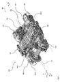
- Figure 1
- is a schematic perspective top view of a preferred embodiment of a running gear according to the present invention comprising a preferred embodiment of the running gear frame according to the present invention and used in a preferred embodiment of the rail vehicle according to the present invention;
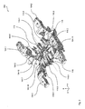
- Figure 2
- is a schematic perspective top view of the running gear frame of
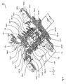
Figure 1 ; - Figure 3
- is a schematic, partially sectional perspective top view of the running gear frame of
Figure 1 ; - Figure 4
- sectional view of a detail of the running gear frame of
Figure 1 (along line IV-IV ofFigure 1 ); - Figure 5
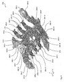
- is a schematic, partially sectional perspective top view of a further preferred embodiment of a running gear frame according to the present invention used the rail vehicle of
Figure 1 (in a view corresponding to the one ofFigure 3 ). - With reference to
Figures 1 to 4 a preferred embodiment of arail vehicle 101 according to the present invention comprising a first preferred embodiment of arunning gear 102 according to the invention will now be described in greater detail. In order to simplify the explanations given below, an xyz-coordinate system has been introduced into the Figures, wherein (on a straight, level track) the x-axis designates the longitudinal direction of therunning gear 102, the y-axis designates the transverse direction of therunning gear 102 and the z-axis designates the height direction of therunning gear 102. - The
vehicle 101 is a high-speed rail vehicle with a nominal operating speed above 250 km/h, more precisely above 300 km/h to 380 km/h. Thevehicle 101 comprises a wagon body (not shown) supported by a suspension system on therunning gear 102. Therunning gear 102 comprises two wheel units in the form of wheel sets 103 supporting a preferred embodiment of arunning gear frame 104 according to the invention via aprimary spring unit 105. Therunning gear frame 104 supports the wagon body via asecondary spring unit 106. - Each
wheel set 103 and is driven by adrive unit 107. Thedrive unit 107 comprises a motor unit 108 (suspended to the running gear frame 104) and a gearing 109 (sitting on the shaft of the wheel set 103) connected via a motor shaft 110. Both driveunits 107 are of substantially identical design and arranged substantially symmetrically with respect to the center of therunning gear frame 104. - As can be seen best from
Figures 2 and3 , therunning gear frame 104 is of generally H-shaped design with a middle section in the form of a transverse beam 104.1 located between the wheel sets 103 and rigidly connecting two longitudinal beams 104.2. The interface of therunning gear 102 to the wagon body (not shown) is formed by a bolster 111 rigidly connected to the wagon body and supported on therunning gear frame 104 via thesecondary spring unit 106. - As can be seen best from
Figure 4 , the transmission of forces in the longitudinal direction (x-direction) between the wagon body and therunning gear frame 104 is provided via atraction linkage 112 comprising a traction linkage element 112.1. A first end of the traction linkage element 112.1 is articulated to the transverse beam 104.1 at a first articulation location 112.2, while a second end of the traction linkage element 112.1 is articulated, at a second articulation location 112.3, to a console element in the form of anelongated arm 113 of the bolster 111. - As can be seen best from
Figures 3 and4 , thetransverse beam 104 is a substantially box shaped element formed by a plurality of wall elements, namely (seen in the positive x-direction) a front wall element 104.3 and a rear wall element 104.4 as well as (seen in the z- direction) an upper wall element 104.5 and a lower wall element 104.6. It is to be noted thatFigure 3 shows a partially sectional view of therunning gear frame 104 where part of the upper wall element 104.5 as well as a part of an upper wall of the right longitudinal beam 104.2 have been removed for providing a better overview over the inner structure of the transverse beam 104.1 and the longitudinal beams 104.2. - The traction linkage element 112.1 is received within a centrally located receptacle 104.7 of the transverse beam 104.1. The receptacle 104.7 is confined by the wall elements 104.3 to 104.6 as well as by two lateral wall elements 104.8 located on both sides of the center of the
running gear frame 104. Each lateral wall element 104.8 is spaced from the respective adjacent longitudinal beam 104.2 and is substantially V-shaped in a view along the height direction, a root section 104.9 of the lateral wall element 104.8 facing away from the traction linkage element 112.1 and towards the associated longitudinal beam 104.2. - These lateral wall elements 104.8 form inner reinforcement wall elements of the transverse beam 104.1. To this end, the lateral wall elements are rigidly connected to the adjacent wall elements 104.3 to 104.6 of the transverse beam 104.1. This configuration has the advantage that, for example, torsional rigidity of the transverse beam 104.1 about the transverse axis (y-direction) is greatly improved. Furthermore, a compact configuration is achieved with a concentrated reinforcement in the area of the
traction linkage 112. - The root section 104.9 of one of the lateral wall elements 104.8 further serves as a structurally highly stable interface for a transverse damping element (only schematically indicated in
Figure 3 by its line of action 114) connected to either the traction linkage element 112.1 or, preferably, to the corresponding interface of theconsole 113. The dampingelement 114 damps motion in the transverse direction (y-direction) between therunning gear frame 104 and the bolster 111. It will be appreciated that, with other embodiments, of the invention such a damping element may be provided at each side of the running gear. - The connection between the traction linkage element 112.1 and the console 113 (at the second articulation location 112.3) is provided via a fork shaped end section 113.1 reaching through an opening 104.10 of the upper wall element 104.5 down into the receptacle 104.7 such that each of its free ends is rigidly connected (e.g. via screws or the like) to a free end of an axle element 112.4 of the traction linkage element 112.1. The axle element 112.2 is received within an elastic bearing (e.g. a conventional rubber bearing) of the traction linkage element 112.1 allowing relative motion between the traction linkage element 112.1 and the axle element 112.2.
- A similar connection is provided at the other, first end of the traction linkage element 112.1 (i.e. at the first articulation location 112.2), where each of the free ends of an further axle element 112.5 (elastically held within the traction linkage element 112.1) is rigidly connected (e.g. via screws or the like) to an adjacent interface element 104.11 rigidly mounted to the front wall 104.3 of the transverse beam 104.1.
- As can be seen from
Figure 2 and3 , alateral stop device 115 comprising two lateral stop elements 115.1 is provided to limit lateral motion of the bolster 111 with respect to the running gear frame 104 (and, hence, also lateral motion of the traction linkage element 112.1) in the transverse direction. The lateral stop elements 115.1 are provided laterally at both sides of the opening 104.10 in the upper wall element 104.5 and are partially located outside the transverse beam 104.1. - Each lateral stop element 115.1 further reaches into the receptacle 104.7 and transversely abuts against an edge section of the upper wall element 104.5 such that a favorable introduction of the transverse forces into the upper wall element 104.5 is achieved predominantly resulting in sheer loads and largely avoiding bending loads in the upper wall element 104.5.
- Furthermore, for the part of the respective lateral stop element 115.1 protruding (in the height direction) from the transverse beam 104.1, two lateral support elements 115.2 are provided. These lateral support elements 115.2 extending in the transverse direction. By this means, proper introduction and support of bending loads into the upper wall 104.5 of the transverse beam 104.1 is achieved. This effect is further improved since the respective lateral support element 115.2 reaches up to the region of the associated inner reinforcement element 104.8 located within the transverse beam (as becomes apparent best from
Figure 3 ). - As can be seen in
Figure 2 and3 , adrive support unit 116 for each one of thedrive units 107 is mounted to the (transversally) central part of the front wall element 104.3 and the rear wall element 104.4, respectively. Eachdrive support unit 116 comprises a lower support structure 116.1 and a plurality of drive support arms 116.2 mounted thereon. Each of the drive support arms 116.2 forms a hook-shaped interface element for thedrive unit 107 to support the latter. - It will be appreciated that the (transversally) central part of the upper wall element 104.5 and of the lower wall element 104.6 (in the longitudinal direction) extends beyond the front wall element 104.3 and the rear wall element 104.4, respectively, such that it also forms a part of the respective drive support unit 116 (thereby providing firm connection between the transverse beam 104.1 and the drive support unit 116). However, with other embodiments of the invention, if present at all, separate top and bottom closures may be provided.
- The
running gear frame 104 is a weight reduced yet structurally highly stable component, weight reduction while keeping structural stability being achieved by several, independently applicable approaches (yet these approaches are preferably combined to achieve the maximum effect). The weight reduction of therunning gear frame 104 achieved by these means is not only beneficial in terms of the overall energy consumption of thevehicle 101. - It is also advantageous in terms of the running stability of the
vehicle 101 at high speeds where a low moment of inertia, in particular about the yaw axis (i.e. the height axis) of therunning gear 102 is favorable. - One of these approaches is to reduce the structure of the transverse beam to a minimum by providing the structural connection between the two longitudinal beams 104.2 in the (longitudinally) central area of the
running gear frame 104 exclusively by the four wall elements 104.3 to 104.6. Hence, a very compact and lightweight configuration is achieved by simply avoiding a conventional structure with two generally box-shaped transverse beams. - In the present example, a further reduction in weight and complexity of the design is achieved by using simple sheet metal elements for the four wall elements 104.3 to 104.6. It will however be appreciated that, with other embodiments of the invention, sandwich elements all the like may be used for the wall elements 104.3 to 104.6.
- Structural stability of this single transverse beam 104.1 receiving the traction linkage elements 112.1 at its inside is, on the one hand, achieved via the inner reinforcement wall elements 104.8 and has been described above.
- Furthermore, structural stability of the transverse beam 104.1 is increased (without noticeably increasing weight) by a longitudinally salient section 104.12 within the front wall section 104.3 and a longitudinally salient section 104.13 within the rear wall section 104.4 of the transverse beam 104.1. Both salient sections 104.12, 104.13 are substantially centrally located (in the transverse direction) and are formed in the area of the receptacle 104.7.
- These salient sections 104.12, 104.13 (in particular, the salient section 104.12 forming the interface to the traction linkage element 112.1) improve the introduction and support of the loads within the transverse beam 104.1. Furthermore, apart from increasing the bending resistance and the torsional resistance (via an increase in the respective second moment of area of the transverse beam 104.1), the salient sections 104.12, 104.13 also locally provide more space for receipt of the traction linkage element 112.1 while keeping the remainder of the transverse beam 104.1 compact.
- As can be seen from
Figure 3 , the salient sections 104.12, 104.13, in the longitudinal direction, provide a maximum longitudinal distance LDmax between the front wall element 104.3 and the rear wall element 104.4 which is 110% of a minimum longitudinal distance LDmin between the front wall element 104.3 and the rear wall section 104.4. In the present example, this LDmin, is in the longitudinal distance between the front wall element 104.3 and the rear wall section 104.4 transversely outside of the salient sections 104.12, 104.13, which is in particular present at the respective connection between the front wall section 104.3 and the rear wall section 104.4 and the longitudinal beam 104.2. - The salient sactions104.12, 104.13, in the transverse direction, extend over a transverse distance TDS of about 45% of the inner transverse distance TDL between the longitudinal beams 104.2. Hence, by this means, only a moderate increase in the size of the transverse beam 104.1 is achieved while obtaining the above advantages.
- It will be appreciated that, with other embodiments of the invention, the transverse distance TDS may vary from 25% to 65% of the longitudinal beam distance TDL, preferably from 35% to 55% of the longitudinal beam distance TDL, more preferably from 40% to 50% of the longitudinal beam distance TDL.
- A further (nevertheless individually applicable) approach followed in the present example for reducing the weight of the
running gear frame 104 is to use a plurality of weight reduced wall elements at several locations within therunning gear frame 104 as will be explained in the following. - This weight reduction approach is based on the idea to modify the structure of the transverse beam (compared to conventional running gear frames of this type) insofar as each of these weight reduced wall elements shows at least one (otherwise nonfunctional) weight reduction recess at a less mechanically stressed location.
- As can be seen, in particular, from
Figure 2 to 4 the presentrunning gear frame 104 shows such weight reduction recesses 104.14 in the upper wall element 104.5, the lower wall element 104.6 and the reinforcement wall elements 104.8 of the transverse beam 104.1 as well as within inner reinforcement elements 104.15 of the longitudinal beams 104.2. Furthermore, such weight reduction recesses 115.3 also provided in the natural support elements 115.2. Finally, such weight reduction recesses 116.3 also provided within the lower support structure 116.1 and within the drive support arms 116.2 of thedrive support unit 116. - It will be further appreciated that such a weight reduction recess 104.14, 115.3, 116.3, typically, insofar distinguishes from other conventional recesses within components or wall elements as its single purpose is the weight reduction achieved. Hence, for this reason, such a weight reduction recess 104.14, 115.3, 116.3 distinguishes from other recesses (such as, for example, the opening 104.10) eventually present for (typically imperatively) providing access to another component of the vehicle or for immediately receiving further components of the vehicle.
- As has been outlined above, the less mechanically stressed location for the weight reduction recess 104.14, 115.3, 115.3, is a location where, in a reference wall element and under any load collective LCi to be expected under normal operation of the
rail vehicle 101, a reference stress RSi occurs that is less than 20% of a maximum reference stress RSmax (that occurs in the reference element). The reference wall element, apart from having a continuous, recess-free wall design, is substantially identical to the corresponding wall element of therunning gear frame 104 showing the weight reduction recess 104.14, 115.3, 116.3 and replaces this recessed wall element. Furthermore, the maximum reference stress RSmax,i is a maximum mechanical stress occurring in the reference wall element under the respective one of the load collectives LCi. - It will be appreciated that the reference stress RSi and the maximum reference stress RSmax,i both are considered for the same load collective LCi, i.e. at the same loading situation of the
running gear frame 104, such that different maximum reference stresses RSmax,i may have to be considered depending on the loading situation. Hence, while certain locations may fulfill the requirements for being identified as a less mechanically stressed location under a first load collective LC1, (to be expected under normal operation of the vehicle and, hence, to be considered), these conditions may not be met under a further, different load collective LC2 (also to be expected under normal operation and, hence, also to be considered). In such a case, the specific location does not qualify as such a less mechanically stressed location in the sense of the present invention, and, hence, no recess is placed at this location. It will be further appreciated that, with certain embodiments of the invention, only those load collectives LCi will have to be considered wherein maximum stresses are to be expected during normal operation of thevehicle 101. - A further advantage of the present embodiment of the
rail vehicle 101 lies within the arrangement of thetraction linkage 112 and its points of articulation providing advantageous transmission of the longitudinal forces resulting when accelerating or braking thevehicle 101 as will be outlined in the following. - Under nominal loading of the
rail vehicle 101, the articulation locations 112.2 and 112.3 (more precisely the pivot axis) of the traction linkage element 112.1, in the height direction, are located at a second and a third height level above a track level (of the track as indicated by the dashedcontour 117 inFigure 1 ) which is substantially identical to the first height level of the wheel unit axis of thewheel units 103. - This arrangement of the articulation locations 112.2 and 112.3 reduces the pitching moment (about the wheel axis) and, hence, the disposition of the
running gear 102 to develop pitching oscillation (i.e. oscillation about a pitching axis running in the transverse direction) of therunning gear frame 104. This is beneficial since such pitching oscillation is adverse in terms of running stability, derailment risk and passenger comfort, in particular, at high speeds. - Furthermore, this solution has the advantage that the articulation locations 112.2 and 112.3 are located comparatively low (in the height direction) such that pitch moments about the wheel-rail contact points are reduced, which may lead to undesired wheel unloading at the leading wheel unit 103 (when accelerating) or at the trailing wheel unit 103 (when braking) which increases the derailment risk.
- With the present arrangement a particularly good compromise between the reduced risk of derailment, the reduction of the disposition to develop pitching oscillation when accelerating or breaking, and the track clearance (relevant, among others, in terms of the aerodynamic properties of the running gear) is achieved.
- It will be appreciated that, in the present example, connection between the components of the
running gear frame 104 is provided using a welding process. However, with other embodiment of the invention, this technique or other connecting techniques may be used either alone or in arbitrary combinations. Furthermore, sheet metal elements as well as cast or forged elements may be used either alone or in arbitrary combinations for the running gear frame. - With reference to
Figure 5 a further preferred embodiment of a running gear 202 according to the invention comprising a preferred embodiment of therunning gear frame 204 will be described in the following. The running gear 202 is also used in thevehicle 101. It will be appreciated that the running gear 202 and, in particular, therunning gear frame 204, in their basic design and functionality largely correspond to therunning gear 102 and the running theframe 104, such that only the differences will be discussed here. In particular, like components are given the same reference numerals increased by the value 100. With respect to the features and properties of these components explicit reference is made to the explanations given above unless explicit deviating statements are made in the following in this respect. - The only difference between the running gear 202 and the
running gear 102 is that the running gear 202 is a non-driven running gear having no drive unit supported therein. Hence, instead of the twodrive support units 116, the running gear 202 comprises twobrake support units 216 each adapted to support a brake unit (not shown in detail). - As can be seen
Figure 5 , abrake support unit 216 for each one of the brake units is mounted to the (transversally) central part of the front wall element 204.3 and the rear wall element 204.4, respectively. Eachbrake support unit 216 comprises a lower support structure 216.1 and a plurality of brake support arms 216.2 mounted thereon. Each of the brake support arms 216.2, at its free end, carries a cast interface element 216.4 for the brake unit to support the latter. - It will be appreciated that, here as well, the (transversally) central part of the upper wall element 204.5 and of the lower wall element 204.6 (in the longitudinal direction) extends beyond the front wall element 204.3 and the rear wall element 204.4, respectively, such that it also forms a part of the respective brake support unit 216 (thereby providing firm connection between the transverse beam 104.1 and the brake support unit 216). However, with other embodiments of the invention, if present at all, separate top and bottom closures may be provided.
- As can be seen from
Figure 5 , a web element 216.5 of the respective support arm 216.2 is provided with a weight reduction recess 216.3 at a less mechanically stressed location fulfilling the requirements as outlined above in the context of the first embodiment. Furthermore, the interface element 216.4 also is provided with a weight reduction recess 216.3 at a less mechanically stressed location fulfilling the requirements as outlined above in the context of the first embodiment. Hence, in this respect, explicit reference is made to the explanations given above. - Although the present invention in the foregoing has only a described in the context of high-speed rail vehicles, it will be appreciated that it may also be applied to any other type of rail vehicle in order to overcome similar problems with respect to a simple solution for generally vibrational problems, such as running stability problems and acoustic problems.
Claims (14)
- A running gear frame for a rail vehicle, comprising- two longitudinal beams (104.2) and- at least one transverse beam (104.1; 204.1);- said beams forming a substantially H-shaped configuration defining a longitudinal direction, a transverse direction and a height direction, said transverse beam (104.1; 204.1) providing a structural connection between said longitudinal beams (104.2) in said transverse direction;- at least one of said beams (104.1, 104.2) and/or at least one further structural component (115, 116; 216) of said running gear frame being formed by a plurality of wall elements (104.3 to 104.6, 104.8, 104.15 115.2, 116.2; 204.3 to 204.6, 216.5);
characterized in that- at least one of said wall elements (104.3 to 104.6, 104.8, 104.15 115.2, 116.2; 204.3 to 204.6, 216.5) is a weight reduced wall element showing at least one otherwise nonfunctional weight reduction recess (104.14, 115.3, 116.3; 216.3) at a less mechanically stressed location;- said less mechanically stressed location being a location where, in a reference wall element and under any load collective to be expected under normal operation of said rail vehicle unit, a reference stress occurs that is less than 5%, preferably less than 10%, more preferably less than 15% to 20%, of a maximum reference stress;- said reference wall element, apart from having a continuous, recess-free wall design, being substantially identical to and replacing said wall element showing said weight reduction recess (104.14, 115.3, 116.3; 216.3);- said maximum reference stress being a maximum mechanical stress occurring in said reference wall element under the respective one of said load collectives. - The running gear frame according to claim 1, wherein- said at least one weight reduced wall element is an upper wall element (104.5; 204.5) and/or a lower wall element (104.6; 204.6) of one of said beams, in particular said transverse beam (104.1; 204.1),
and/or- said at least one weight reduced wall element is an inner reinforcement wall element (104.8) of one of said beams
and/or- said at least one weight reduced wall element is a support element (115.2) of a lateral stop element (115.1) of said transverse beam (104.1; 204.1). - The running gear frame according to claim 1 or 2, wherein- said at least one further structural component is a drive support unit (116) for a drive unit (107);- said at least one weight reduced wall element being a wall element of said drive support unit (116).
- The running gear frame according to claim 3, wherein- said drive support unit (116) comprises at least one drive support arm adapted to support said drive unit (107), said at least one weight reduced wall element being a wall element of said drive support arm (116.2), in particular, a web element of said drive support arm (116.2)
and/or- said drive support unit (116) comprises at least one drive interface element (116.2) adapted to form a support interface for said drive unit (107), said at least one weight reduced wall element being a wall element of said drive interface (116.2) element, in particular, a hook-shaped element of said interface element (116.2). - The running gear frame according to any one of claims 1 to 4, wherein- said at least one further structural component is a brake support unit (216) for a brake unit;- said at least one weight reduced wall element being a wall element of said brake support unit (216).
- The running gear frame according to claim 5, wherein- said brake support unit (216) comprises at least one brake support arm (216.2) adapted to support said brake unit, said at least one weight reduced wall element being a wall element of said brake support arm (216.2), in particular, a web element (216.5) of said brake support arm (216.2)
and/or- said brake support unit (216) comprises at least one brake interface element (216.4) adapted to form a support interface for said brake unit, said at least one weight reduced wall element being a wall element of said brake interface element (216.4), in particular, a hook-shaped element of said interface element. - The running gear frame according to any one of claims 1 to 6, wherein- said transverse beam (104.1; 204.1) is formed by a front wall element (104.3), a rear wall element (104.4; 204.4), an upper wall element (104.5; 204.5) and a lower wall element (104.6; 204.6);- in the area of said transverse beam (104.1; 204.1), said structural connection between said longitudinal beams (104.2) being exclusively provided via said front wall element (104.3), said rear wall element (104.4; 204.4), said upper wall element (104.5; 204.5) and said lower wall element (104.6; 204.6)
and/or- said front wall element (104.3) and/or said rear wall element (104.4; 204.4) exclusively being formed by a sheet metal element, said sheet metal element, in particular, being a single layer element. - The running gear frame according to any one of claims 1 to 7, wherein- said at least one weight reduced wall element (104.3 to 104.6, 104.8, 104.15 115.2, 116.2; 204.3 to 204.6, 216.5) is connected to another one of said wall elements (104.3 to 104.6, 104.8, 104.15 115.2, 116.2; 204.3 to 204.6, 216.5) using a welding process;- said at least one weight reduced wall element (104.3 to 104.6, 104.8, 104.15 115.2, 116.2; 204.3 to 204.6, 216.5), in particular, being a cast element or a sheet metal element.
- The running gear frame according to any one of claims 1 to 9, wherein- said transverse beam (104.1; 204.1) has a centrally located receptacle (104.7), said receptacle (104.7), in particular, comprising an interface element for a traction linkage element (112.1) adapted to connect a supported vehicle component (111) and said running gear frame in said longitudinal direction;- said transverse beam (104.1; 204.1), in the region of said centrally located receptacle (104.7), has a longitudinally salient section (104.12, 104.13) within at least one of a front wall section and a rear wall section;- said salient section (104.12, 104.13), in particular, in said longitudinal direction, providing a maximum longitudinal distance between said front wall section and said rear wall section which is 105% to 130%, preferably 110% to 120%, more preferably 110% to 115%, of a minimum longitudinal distance between said front wall section and said rear wall section.
- The running gear frame according to claim 9, wherein- said transverse beam (104.1; 204.1) has at least one lateral wall element (104.8) confining said centrally located receptacle (104.7);- said lateral wall element (104.8) being spaced from an adjacent one of said longitudinal beams (104.2),
wherein, in particular,- said transverse beam (104.1; 204.1) is formed by a wall element set consisting of a front wall element (104.3), a rear wall element (104.4; 204.4), an upper wall element (104.5; 204.5) and a lower wall element (104.6; 204.6), said lateral wall element (104.8) forming an inner reinforcement element of said transverse beam (104.1; 204.1) rigidly connected to at least two, preferably at least three, more preferably all, of said walls of said wall element set,
and/or- said lateral wall element (104.8), in a view along said height direction is substantially V-shaped, a root section of said V-shaped lateral wall element (104.8), in particular, facing away from said traction linkage element (112.1). - The running gear frame according to any one of claims 1 to 10, wherein- said transverse beam (104.1; 204.1), in the region of said centrally located receptacle (104.7), has at least one lateral stop element (115.1) adapted to limit lateral motion of said traction linkage element (112.1) in said transverse direction,
wherein, in particular,- said lateral stop element (115.1) is at least partially located outside said transverse beam (104.1; 204.1)
and/or- said lateral wall element (104.8) is located in the region of an upper wall section of said transverse beam (104.1; 204.1)
and/or- said lateral stop element (115.1) protrudes, in said height direction, from said transverse beam (104.1; 204.1), at least one lateral support element (115.2) being associated to said lateral stop element (115.1), said lateral support element (115.2) extending in said transverse direction, in particular up to the region of an inner reinforcement element (104.8) located within said transverse beam (104.1; 204.1). - A running gear with a running gear frame (104; 204) according to any one of claims 1 to 11.
- The running gear according to claim 12, wherein it is adapted for a nominal operating speed above 250 km/h, preferably above 300 km/h, more preferably above 350 km/h.
- A rail vehicle with a running gear (102; 202) according to claim 12 or 13.
Priority Applications (3)
| Application Number | Priority Date | Filing Date | Title |
|---|---|---|---|
| EP20110158515 EP2500232B1 (en) | 2011-03-16 | 2011-03-16 | Weight reduced running gear frame for a rail vehicle |
| ES11158515.4T ES2470331T3 (en) | 2011-03-16 | 2011-03-16 | Reduced undercarriage frame for a rail vehicle |
| CN2012100692592A CN102673598A (en) | 2011-03-16 | 2012-03-15 | Weight reduced running gear frame for a rail vehicle |
Applications Claiming Priority (1)
| Application Number | Priority Date | Filing Date | Title |
|---|---|---|---|
| EP20110158515 EP2500232B1 (en) | 2011-03-16 | 2011-03-16 | Weight reduced running gear frame for a rail vehicle |
Publications (2)
| Publication Number | Publication Date |
|---|---|
| EP2500232A1 EP2500232A1 (en) | 2012-09-19 |
| EP2500232B1 true EP2500232B1 (en) | 2014-04-30 |
Family
ID=44318510
Family Applications (1)
| Application Number | Title | Priority Date | Filing Date |
|---|---|---|---|
| EP20110158515 Not-in-force EP2500232B1 (en) | 2011-03-16 | 2011-03-16 | Weight reduced running gear frame for a rail vehicle |
Country Status (3)
| Country | Link |
|---|---|
| EP (1) | EP2500232B1 (en) |
| CN (1) | CN102673598A (en) |
| ES (1) | ES2470331T3 (en) |
Families Citing this family (2)
| Publication number | Priority date | Publication date | Assignee | Title |
|---|---|---|---|---|
| CN104802821A (en) * | 2015-04-29 | 2015-07-29 | 长春轨道客车股份有限公司 | Novel high-speed motor train unit non-power bogie |
| CN104802822A (en) * | 2015-04-29 | 2015-07-29 | 长春轨道客车股份有限公司 | Trailer bogie framework for standard EMU (Electric Multiple Units) |
Family Cites Families (3)
| Publication number | Priority date | Publication date | Assignee | Title |
|---|---|---|---|---|
| GB384036A (en) * | 1931-10-21 | 1932-12-01 | George Harrison Sheffield | Improvements in bogie trucks for railway and like vehicles |
| US2090498A (en) * | 1936-01-10 | 1937-08-17 | American Car & Foundry Co | Welded truck |
| IT1259517B (en) * | 1992-04-03 | 1996-03-20 | Fiat Ferroviaria Spa | TROLLEY FOR HIGH PERFORMANCE RAILWAY VEHICLES |
-
2011
- 2011-03-16 ES ES11158515.4T patent/ES2470331T3/en active Active
- 2011-03-16 EP EP20110158515 patent/EP2500232B1/en not_active Not-in-force
-
2012
- 2012-03-15 CN CN2012100692592A patent/CN102673598A/en active Pending
Also Published As
| Publication number | Publication date |
|---|---|
| CN102673598A (en) | 2012-09-19 |
| EP2500232A1 (en) | 2012-09-19 |
| ES2470331T3 (en) | 2014-06-23 |
Similar Documents
| Publication | Publication Date | Title |
|---|---|---|
| EP2557015B1 (en) | Running gear unit for a rail vehicle | |
| EP2500233B1 (en) | Rail vehicle unit with a traction linkage | |
| EP2669138B1 (en) | Running gear frame for a rail vehicle | |
| CN110143213A (en) | A kind of Draft gear of bogie and its application | |
| CN201276119Y (en) | Axle box resilient suspension system for bogie | |
| US9205874B2 (en) | Wheel suspension for a motor vehicle | |
| CN104554324B (en) | A kind of monoblock type framework and bogie | |
| RU2544259C2 (en) | Undercarriage frame for rail vehicles | |
| EP3473515B1 (en) | Frame of bogie | |
| CN103465923A (en) | Rail vehicle unit | |
| CN107234934A (en) | A kind of multi-connecting-rod separated suspension for commercial car drive axle | |
| CN111348067B (en) | Bogie and rail vehicle | |
| CN110155111A (en) | The bogie frame of rail vehicle, the bogie of rail vehicle and rail vehicle | |
| EP2500232B1 (en) | Weight reduced running gear frame for a rail vehicle | |
| CN111959550A (en) | Framework and bogie thereof | |
| CN103538628B (en) | A kind of body frame structure for automotive and there is the automobile of this body frame structure for automotive | |
| CN111232009B (en) | Side beam, framework and bogie | |
| CN102490745A (en) | Secondary suspension device for high-speed railway wagon bogie | |
| CA2874732C (en) | Running gear unit for a rail vehicle | |
| CN109823396B (en) | Rear frame assembly of chassis of vehicle body | |
| CN116812006B (en) | Frame, chassis and vehicle | |
| JPH09301163A (en) | Bolsterless truck for rolling stock | |
| CN110091687A (en) | Five link lever rear suspensions and vehicle structure with the rear suspension | |
| JPH02151581A (en) | Under carriage frame for truck |
Legal Events
| Date | Code | Title | Description |
|---|---|---|---|
| PUAI | Public reference made under article 153(3) epc to a published international application that has entered the european phase |
Free format text: ORIGINAL CODE: 0009012 |
|
| AK | Designated contracting states |
Kind code of ref document: A1 Designated state(s): AL AT BE BG CH CY CZ DE DK EE ES FI FR GB GR HR HU IE IS IT LI LT LU LV MC MK MT NL NO PL PT RO RS SE SI SK SM TR |
|
| AX | Request for extension of the european patent |
Extension state: BA ME |
|
| 17P | Request for examination filed |
Effective date: 20130319 |
|
| GRAP | Despatch of communication of intention to grant a patent |
Free format text: ORIGINAL CODE: EPIDOSNIGR1 |
|
| INTG | Intention to grant announced |
Effective date: 20130515 |
|
| GRAS | Grant fee paid |
Free format text: ORIGINAL CODE: EPIDOSNIGR3 |
|
| GRAP | Despatch of communication of intention to grant a patent |
Free format text: ORIGINAL CODE: EPIDOSNIGR1 |
|
| INTG | Intention to grant announced |
Effective date: 20131023 |
|
| GRAA | (expected) grant |
Free format text: ORIGINAL CODE: 0009210 |
|
| AK | Designated contracting states |
Kind code of ref document: B1 Designated state(s): AL AT BE BG CH CY CZ DE DK EE ES FI FR GB GR HR HU IE IS IT LI LT LU LV MC MK MT NL NO PL PT RO RS SE SI SK SM TR |
|
| REG | Reference to a national code |
Ref country code: GB Ref legal event code: FG4D Ref country code: CH Ref legal event code: EP |
|
| REG | Reference to a national code |
Ref country code: AT Ref legal event code: REF Ref document number: 664909 Country of ref document: AT Kind code of ref document: T Effective date: 20140515 |
|
| REG | Reference to a national code |
Ref country code: IE Ref legal event code: FG4D |
|
| REG | Reference to a national code |
Ref country code: DE Ref legal event code: R096 Ref document number: 602011006467 Country of ref document: DE Effective date: 20140612 |
|
| REG | Reference to a national code |
Ref country code: CH Ref legal event code: NV Representative=s name: TROESCH SCHEIDEGGER WERNER AG, CH |
|
| REG | Reference to a national code |
Ref country code: ES Ref legal event code: FG2A Ref document number: 2470331 Country of ref document: ES Kind code of ref document: T3 Effective date: 20140623 |
|
| REG | Reference to a national code |
Ref country code: NL Ref legal event code: T3 |
|
| REG | Reference to a national code |
Ref country code: LT Ref legal event code: MG4D |
|
| PG25 | Lapsed in a contracting state [announced via postgrant information from national office to epo] |
Ref country code: FI Free format text: LAPSE BECAUSE OF FAILURE TO SUBMIT A TRANSLATION OF THE DESCRIPTION OR TO PAY THE FEE WITHIN THE PRESCRIBED TIME-LIMIT Effective date: 20140430 Ref country code: IS Free format text: LAPSE BECAUSE OF FAILURE TO SUBMIT A TRANSLATION OF THE DESCRIPTION OR TO PAY THE FEE WITHIN THE PRESCRIBED TIME-LIMIT Effective date: 20140830 Ref country code: LT Free format text: LAPSE BECAUSE OF FAILURE TO SUBMIT A TRANSLATION OF THE DESCRIPTION OR TO PAY THE FEE WITHIN THE PRESCRIBED TIME-LIMIT Effective date: 20140430 Ref country code: NO Free format text: LAPSE BECAUSE OF FAILURE TO SUBMIT A TRANSLATION OF THE DESCRIPTION OR TO PAY THE FEE WITHIN THE PRESCRIBED TIME-LIMIT Effective date: 20140730 Ref country code: CY Free format text: LAPSE BECAUSE OF FAILURE TO SUBMIT A TRANSLATION OF THE DESCRIPTION OR TO PAY THE FEE WITHIN THE PRESCRIBED TIME-LIMIT Effective date: 20140430 Ref country code: GR Free format text: LAPSE BECAUSE OF FAILURE TO SUBMIT A TRANSLATION OF THE DESCRIPTION OR TO PAY THE FEE WITHIN THE PRESCRIBED TIME-LIMIT Effective date: 20140731 Ref country code: BG Free format text: LAPSE BECAUSE OF FAILURE TO SUBMIT A TRANSLATION OF THE DESCRIPTION OR TO PAY THE FEE WITHIN THE PRESCRIBED TIME-LIMIT Effective date: 20140730 |
|
| PG25 | Lapsed in a contracting state [announced via postgrant information from national office to epo] |
Ref country code: HR Free format text: LAPSE BECAUSE OF FAILURE TO SUBMIT A TRANSLATION OF THE DESCRIPTION OR TO PAY THE FEE WITHIN THE PRESCRIBED TIME-LIMIT Effective date: 20140430 Ref country code: SE Free format text: LAPSE BECAUSE OF FAILURE TO SUBMIT A TRANSLATION OF THE DESCRIPTION OR TO PAY THE FEE WITHIN THE PRESCRIBED TIME-LIMIT Effective date: 20140430 Ref country code: RS Free format text: LAPSE BECAUSE OF FAILURE TO SUBMIT A TRANSLATION OF THE DESCRIPTION OR TO PAY THE FEE WITHIN THE PRESCRIBED TIME-LIMIT Effective date: 20140430 Ref country code: LV Free format text: LAPSE BECAUSE OF FAILURE TO SUBMIT A TRANSLATION OF THE DESCRIPTION OR TO PAY THE FEE WITHIN THE PRESCRIBED TIME-LIMIT Effective date: 20140430 Ref country code: PL Free format text: LAPSE BECAUSE OF FAILURE TO SUBMIT A TRANSLATION OF THE DESCRIPTION OR TO PAY THE FEE WITHIN THE PRESCRIBED TIME-LIMIT Effective date: 20140430 |
|
| PG25 | Lapsed in a contracting state [announced via postgrant information from national office to epo] |
Ref country code: PT Free format text: LAPSE BECAUSE OF FAILURE TO SUBMIT A TRANSLATION OF THE DESCRIPTION OR TO PAY THE FEE WITHIN THE PRESCRIBED TIME-LIMIT Effective date: 20140901 |
|
| PG25 | Lapsed in a contracting state [announced via postgrant information from national office to epo] |
Ref country code: RO Free format text: LAPSE BECAUSE OF FAILURE TO SUBMIT A TRANSLATION OF THE DESCRIPTION OR TO PAY THE FEE WITHIN THE PRESCRIBED TIME-LIMIT Effective date: 20140430 Ref country code: EE Free format text: LAPSE BECAUSE OF FAILURE TO SUBMIT A TRANSLATION OF THE DESCRIPTION OR TO PAY THE FEE WITHIN THE PRESCRIBED TIME-LIMIT Effective date: 20140430 Ref country code: DK Free format text: LAPSE BECAUSE OF FAILURE TO SUBMIT A TRANSLATION OF THE DESCRIPTION OR TO PAY THE FEE WITHIN THE PRESCRIBED TIME-LIMIT Effective date: 20140430 Ref country code: CZ Free format text: LAPSE BECAUSE OF FAILURE TO SUBMIT A TRANSLATION OF THE DESCRIPTION OR TO PAY THE FEE WITHIN THE PRESCRIBED TIME-LIMIT Effective date: 20140430 Ref country code: SK Free format text: LAPSE BECAUSE OF FAILURE TO SUBMIT A TRANSLATION OF THE DESCRIPTION OR TO PAY THE FEE WITHIN THE PRESCRIBED TIME-LIMIT Effective date: 20140430 |
|
| REG | Reference to a national code |
Ref country code: DE Ref legal event code: R097 Ref document number: 602011006467 Country of ref document: DE |
|
| PLBE | No opposition filed within time limit |
Free format text: ORIGINAL CODE: 0009261 |
|
| STAA | Information on the status of an ep patent application or granted ep patent |
Free format text: STATUS: NO OPPOSITION FILED WITHIN TIME LIMIT |
|
| 26N | No opposition filed |
Effective date: 20150202 |
|
| REG | Reference to a national code |
Ref country code: DE Ref legal event code: R097 Ref document number: 602011006467 Country of ref document: DE Effective date: 20150202 |
|
| PG25 | Lapsed in a contracting state [announced via postgrant information from national office to epo] |
Ref country code: SI Free format text: LAPSE BECAUSE OF FAILURE TO SUBMIT A TRANSLATION OF THE DESCRIPTION OR TO PAY THE FEE WITHIN THE PRESCRIBED TIME-LIMIT Effective date: 20140430 |
|
| PG25 | Lapsed in a contracting state [announced via postgrant information from national office to epo] |
Ref country code: MC Free format text: LAPSE BECAUSE OF FAILURE TO SUBMIT A TRANSLATION OF THE DESCRIPTION OR TO PAY THE FEE WITHIN THE PRESCRIBED TIME-LIMIT Effective date: 20140430 Ref country code: LU Free format text: LAPSE BECAUSE OF FAILURE TO SUBMIT A TRANSLATION OF THE DESCRIPTION OR TO PAY THE FEE WITHIN THE PRESCRIBED TIME-LIMIT Effective date: 20150316 |
|
| GBPC | Gb: european patent ceased through non-payment of renewal fee |
Effective date: 20150316 |
|
| REG | Reference to a national code |
Ref country code: IE Ref legal event code: MM4A |
|
| PG25 | Lapsed in a contracting state [announced via postgrant information from national office to epo] |
Ref country code: IE Free format text: LAPSE BECAUSE OF NON-PAYMENT OF DUE FEES Effective date: 20150316 Ref country code: GB Free format text: LAPSE BECAUSE OF NON-PAYMENT OF DUE FEES Effective date: 20150316 |
|
| REG | Reference to a national code |
Ref country code: FR Ref legal event code: PLFP Year of fee payment: 6 |
|
| PGFP | Annual fee paid to national office [announced via postgrant information from national office to epo] |
Ref country code: TR Payment date: 20160226 Year of fee payment: 6 Ref country code: CH Payment date: 20160323 Year of fee payment: 6 Ref country code: NL Payment date: 20160321 Year of fee payment: 6 Ref country code: ES Payment date: 20160309 Year of fee payment: 6 Ref country code: DE Payment date: 20160321 Year of fee payment: 6 |
|
| PGFP | Annual fee paid to national office [announced via postgrant information from national office to epo] |
Ref country code: BE Payment date: 20160321 Year of fee payment: 6 Ref country code: AT Payment date: 20160322 Year of fee payment: 6 Ref country code: FR Payment date: 20160321 Year of fee payment: 6 |
|
| PGFP | Annual fee paid to national office [announced via postgrant information from national office to epo] |
Ref country code: IT Payment date: 20160324 Year of fee payment: 6 |
|
| PG25 | Lapsed in a contracting state [announced via postgrant information from national office to epo] |
Ref country code: MT Free format text: LAPSE BECAUSE OF FAILURE TO SUBMIT A TRANSLATION OF THE DESCRIPTION OR TO PAY THE FEE WITHIN THE PRESCRIBED TIME-LIMIT Effective date: 20140430 |
|
| PG25 | Lapsed in a contracting state [announced via postgrant information from national office to epo] |
Ref country code: SM Free format text: LAPSE BECAUSE OF FAILURE TO SUBMIT A TRANSLATION OF THE DESCRIPTION OR TO PAY THE FEE WITHIN THE PRESCRIBED TIME-LIMIT Effective date: 20140430 Ref country code: HU Free format text: LAPSE BECAUSE OF FAILURE TO SUBMIT A TRANSLATION OF THE DESCRIPTION OR TO PAY THE FEE WITHIN THE PRESCRIBED TIME-LIMIT; INVALID AB INITIO Effective date: 20110316 |
|
| REG | Reference to a national code |
Ref country code: DE Ref legal event code: R119 Ref document number: 602011006467 Country of ref document: DE |
|
| REG | Reference to a national code |
Ref country code: CH Ref legal event code: PL |
|
| REG | Reference to a national code |
Ref country code: NL Ref legal event code: MM Effective date: 20170401 |
|
| REG | Reference to a national code |
Ref country code: AT Ref legal event code: MM01 Ref document number: 664909 Country of ref document: AT Kind code of ref document: T Effective date: 20170316 |
|
| REG | Reference to a national code |
Ref country code: FR Ref legal event code: ST Effective date: 20171130 |
|
| PG25 | Lapsed in a contracting state [announced via postgrant information from national office to epo] |
Ref country code: DE Free format text: LAPSE BECAUSE OF NON-PAYMENT OF DUE FEES Effective date: 20171003 Ref country code: FR Free format text: LAPSE BECAUSE OF NON-PAYMENT OF DUE FEES Effective date: 20170331 Ref country code: AT Free format text: LAPSE BECAUSE OF NON-PAYMENT OF DUE FEES Effective date: 20170316 Ref country code: NL Free format text: LAPSE BECAUSE OF NON-PAYMENT OF DUE FEES Effective date: 20170401 |
|
| PG25 | Lapsed in a contracting state [announced via postgrant information from national office to epo] |
Ref country code: CH Free format text: LAPSE BECAUSE OF NON-PAYMENT OF DUE FEES Effective date: 20170331 Ref country code: LI Free format text: LAPSE BECAUSE OF NON-PAYMENT OF DUE FEES Effective date: 20170331 Ref country code: IT Free format text: LAPSE BECAUSE OF NON-PAYMENT OF DUE FEES Effective date: 20170316 |
|
| REG | Reference to a national code |
Ref country code: BE Ref legal event code: MM Effective date: 20170331 |
|
| PG25 | Lapsed in a contracting state [announced via postgrant information from national office to epo] |
Ref country code: BE Free format text: LAPSE BECAUSE OF NON-PAYMENT OF DUE FEES Effective date: 20170331 |
|
| PG25 | Lapsed in a contracting state [announced via postgrant information from national office to epo] |
Ref country code: MK Free format text: LAPSE BECAUSE OF FAILURE TO SUBMIT A TRANSLATION OF THE DESCRIPTION OR TO PAY THE FEE WITHIN THE PRESCRIBED TIME-LIMIT Effective date: 20140430 |
|
| REG | Reference to a national code |
Ref country code: ES Ref legal event code: FD2A Effective date: 20180705 |
|
| PG25 | Lapsed in a contracting state [announced via postgrant information from national office to epo] |
Ref country code: ES Free format text: LAPSE BECAUSE OF NON-PAYMENT OF DUE FEES Effective date: 20170317 |
|
| PG25 | Lapsed in a contracting state [announced via postgrant information from national office to epo] |
Ref country code: AL Free format text: LAPSE BECAUSE OF FAILURE TO SUBMIT A TRANSLATION OF THE DESCRIPTION OR TO PAY THE FEE WITHIN THE PRESCRIBED TIME-LIMIT Effective date: 20140430 |
|
| PG25 | Lapsed in a contracting state [announced via postgrant information from national office to epo] |
Ref country code: TR Free format text: LAPSE BECAUSE OF NON-PAYMENT OF DUE FEES Effective date: 20170316 |