EP2500182B1 - Sicherungsvorrichtung für Speichen - Google Patents
Sicherungsvorrichtung für Speichen Download PDFInfo
- Publication number
- EP2500182B1 EP2500182B1 EP11190656.6A EP11190656A EP2500182B1 EP 2500182 B1 EP2500182 B1 EP 2500182B1 EP 11190656 A EP11190656 A EP 11190656A EP 2500182 B1 EP2500182 B1 EP 2500182B1
- Authority
- EP
- European Patent Office
- Prior art keywords
- spoke
- fixing
- fixing member
- rim
- hole
- Prior art date
- Legal status (The legal status is an assumption and is not a legal conclusion. Google has not performed a legal analysis and makes no representation as to the accuracy of the status listed.)
- Not-in-force
Links
- 238000009434 installation Methods 0.000 claims description 16
- XLYOFNOQVPJJNP-UHFFFAOYSA-N water Substances O XLYOFNOQVPJJNP-UHFFFAOYSA-N 0.000 description 4
- 230000005540 biological transmission Effects 0.000 description 1
Images


Classifications
-
- B—PERFORMING OPERATIONS; TRANSPORTING
- B60—VEHICLES IN GENERAL
- B60B—VEHICLE WHEELS; CASTORS; AXLES FOR WHEELS OR CASTORS; INCREASING WHEEL ADHESION
- B60B21/00—Rims
- B60B21/06—Rims characterised by means for attaching spokes, i.e. spoke seats
- B60B21/062—Rims characterised by means for attaching spokes, i.e. spoke seats for bicycles
-
- B—PERFORMING OPERATIONS; TRANSPORTING
- B60—VEHICLES IN GENERAL
- B60B—VEHICLE WHEELS; CASTORS; AXLES FOR WHEELS OR CASTORS; INCREASING WHEEL ADHESION
- B60B21/00—Rims
- B60B21/06—Rims characterised by means for attaching spokes, i.e. spoke seats
-
- B—PERFORMING OPERATIONS; TRANSPORTING
- B60—VEHICLES IN GENERAL
- B60Y—INDEXING SCHEME RELATING TO ASPECTS CROSS-CUTTING VEHICLE TECHNOLOGY
- B60Y2200/00—Type of vehicle
- B60Y2200/10—Road Vehicles
- B60Y2200/13—Bicycles; Tricycles
Definitions
- the present invention relates to a securing device for spokes, and more particularly, to a securing device for guiding the spokes and firmly securing spokes to the rim.
- a conventional wheel is composed of a rim, a hub at the center of the rim and spokes connected between the rim and the hub.
- Each spoke has one end connected to the hub and the other end of the spoke extends through the rim and secured by a securing member.
- the conventional rim includes multiple holes and the spokes each have a threaded section which extends through the hole, and the securing member has inner threads is securely connected to the threaded section to secure the spoke. By the spokes, the rim does not deform during use.
- the spoke When securing the spokes, the spoke is inclined in the hole of the rim, or the hole is inclined for connecting the spoke.
- the securing way affects the force transmission of the spokes and relates to the performance of the spokes and the rim.
- Taiwan Utility Patent No. 099204627 discloses a nut which is a hollow nut with a threaded section defined in the inner periphery of the passage thereof and has a cross-shaped outer appearance.
- the distal end of the nut includes continuous wave-shaped profile and a spherical portion is formed at the mediate portion of the nut. Multiple recesses are defined in the spherical portion and the front section of the nut is tapered.
- the nut is located in the hole of the rim and the distal end is threadedly connected to the threaded section of the spoke.
- the spherical portion is used to adjust the angle of the spoke and the rim and the recesses reinforce the connection.
- Taiwan Utility Patent No. 099209270 discloses a rim with an inner rim and an outer rim, wherein the inner rim having walls extending radially therefrom, and the outer rim is fixed to the walls.
- the inner rim includes multiple holes and each hole has an axis which is inclined relative to the base surface of the inner wall.
- An opening is defined at the inner rim and located close to the outer rim.
- the inner rim includes a surface defined along the periphery of the opening and located around the hole. The axis of the hole is perpendicular to the surface.
- the first example uses the spherical portion to adjust the angle between the spoke and the rim, and the recesses to secure the connection between the spoke and the rim.
- the second example provides an opening in the inner rim and the opening is inclined relative to the axis of the hole in the rim.
- the securing member is perpendicular to the hole so that the securing member is connected to the spoke at an angle. Another securing member can be connected to the spoke to further secure the spoke.
- the spoke is easily deformed due to the loosened or broken spokes.
- the opening is difficult to make and the inclination of the surface is fixed which restricts the position of the securing member.
- the securing member and the fixing member have the same threading direction which makes the spoke to be loosened easily.
- the present invention relates to a securing device of a rim and comprises a rim having a connection bridge with two walls extending therefrom, and multiple installation holes are defined through the connection bridge.
- Multiple spoke units each have a spoke, a first fixing member and a second fixing member.
- Each spoke has a first end connected to a hub and a second end of each spoke has an outer threaded section which extends through the installation hole.
- the first fixing member has a first fixing portion which includes inner threads.
- the first fixing portion is threadedly connected to the outer threaded section of the spoke.
- a second fixing portion and a third fixing portion extend from the first fixing member with the second fixing portion located between the first and third fixing portions.
- the third fixing portion has outer threads and a passage is defined through the first, second and third fixing portions, so that the spoke extends through the passage.
- the second fixing member is slipped over the spoke.
- a connection portion has inner threads defined in the second fixing member and the connection portion is threadedly connected to the third fixing portion.
- An object of the invention is therefore a securing device of a rim comprising:
- the primary object of the present invention is to provide a securing device for connecting spokes to the rim, wherein a first fixing member is located on outside of the rim to threadedly connected to the spoke, and a second fixing member and a third fixing member are located at inside of the rim to further secure and guide the first fixing member.
- the second object of the present invention is to provide a securing device for connecting spokes to the rim, wherein the second fixing member reinforces the second and third fixing portions of the first fixing member so as to prevent the spoke from being broken.
- the third object of the present invention is to provide a securing device for connecting spokes to the rim, wherein the outer threads of the third fixing portion and the outer threaded section of the spoke have opposite threading directions, so that when the first fixing member is loosened, the second fixing member is secured.
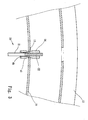
- the securing device for securing a spoke to a rim of the present invention comprises a rim 10 and multiple spoke units 20.
- the rim 10 is a U-shaped rim and includes a connection bridge 11 and two walls 12 extend from the connection bridge 11. Multiple installation holes 13 are defined through the connection bridge 11.
- Each of the multiple spoke units 20 includes a spoke 21, a first fixing member 30 and a second fixing member 40.
- Each spoke 21 has a first end connected to a hub and a second end of each spoke 21 has an outer threaded section 22 which extends through the installation hole 13.
- the first fixing member 30 is a tubular member and has a first fixing portion 31 which includes inner threads.
- a second fixing portion 32 and a third fixing portion 33 extend from the first fixing portion 31 with the second fixing portion 32 located between the first 31 and third 33 fixing portions.
- the third fixing portion 33 has outer threads and the outer threads of the third fixing portion 33 and the outer threaded section 22 of the spoke 21 have opposite threading directions.
- a passage 34 is defined through the first, second and third fixing portions 31, 32, 33, and the spoke 21 extends through the passage 34.
- a first guide portion 35 protrudes form the connection portion between the first fixing member 30 and the second fixing portion 32.
- the second and third fixing portions 32, 33 are located at the inside of the rim 10.
- the first fixing portion 31 is threadedly connected to the outer threaded section 22 of the spoke 21.
- the curvature of the curved first guide portion 35 is matched with the installation hole 13 to adjust the angle of the spoke 21 relative to the rim 10.
- the second fixing member 40 is a tubular member and slipped over the spoke 21.
- a connection portion 41 has inner threads defined in the second fixing member 40.
- a first hole 42 is defined in the first end of the connection portion 41 of the second fixing member 40 and a second hole 43 is defined in the second end of the second fixing member 40.
- the caliber of the first hole 42 is matched with the second fixing portion 32 so as to guide the first fixing member 30.
- the connection portion 41 is threadedly connected to the third fixing portion 33.
- the second fixing portion 32 extends through the first hole 42, so that when the first fixing member 30 is secured, the second fixing member 40 provides guidance to the first fixing member 30 and prevents the first fixing member 30 from being loosened.
- the second fixing member 40 has a second curved guide portion 44 located around the first hole 42 and the outer shape of the second curved guide portion 44 is matched with the installation hole 13 to adjust the spoke 21 relative to the rim 10.
- a pad 45 is located in the second hole 43 to keep water out from the first and second fixing members 30, 40, and the pad 45 is located between the third fixing portion 33 and the connection portion 41 to prevent the two parts from being loosened and entry of water.
- the first fixing member 30 When in assembling, the first fixing member 30 extends through the installation hole 13 in the rim 10, and the second and third fixing portions 32, 33 extend through the installation hole 13 and located at the inside of the rim 10.
- the spoke 21 extends through the second fixing member 40, the installation hole 13 and the passage 34 of the first fixing member 31.
- the first fixing portion 31 of the first fixing member 30 is threadedly connected to the outer threaded section 22 of the spoke 21.
- the first guide portion 35 is installed according the angle of the spoke 21 to be installed.
- the second fixing member 40 is then connected to the second and third fixing portions 32, 33.
- the connection portion 41 is threadedly connected to the third fixing portion 33, and the pad 45 is then inserted into the second hole 43.
- the second fixing member 40 is first loosened and the first fixing member 30 is then loosened to adjust or replace the spoke 21.
- the first fixing member 30 is guided and secured by connecting the second fixing member 40 and the first fixing member 30, and by connection of the fixing member 40 and the third fixing portion 33.
- the second fixing member 40 reinforces the second and third fixing portions 32, 33 to prevent the spoke 21 from being broken.
- the outer threads of the third fixing portion 33 and the outer threaded section 22 of the spoke 21 have opposite threading directions so that when the first fixing member 30 is loosened, the second fixing member 40 is secured to prevent the first fixing member 30 from being loosened.
- the pad 45 is located in the second hole 43 to keep water out from the first and second fixing members 30, 40, and the pad 45 is located between the third fixing portion 33 and the connection portion 41 to prevent the two parts from being loosened and entry of water.
Landscapes
- Engineering & Computer Science (AREA)
- Mechanical Engineering (AREA)
- Connection Of Plates (AREA)
- Toys (AREA)
Claims (5)
- Sicherungsvorrichtung für eine Felge, umfassend:eine Felge (10), die eine Verbindungsbrücke (11) und zwei Wände (12) aufweist, die von der Verbindungsbrücke (11) aus verlaufen, wobei mehrere Montagelöcher (13) durch die Verbindungsbrücke (11) hindurch festgelegt sind;mehrere Speicheneinheiten (20) und wobei jede Speicheneinheit (20) eine Speiche (21), ein erstes Befestigungselement (30) und ein zweites Befestigungselement (40) aufweist, jede Speiche (21) ein erstes Ende aufweist, das so ausgelegt ist, dass es mit einer Nabe verbunden wird, und ein zweites Ende jeder Speiche (21) einen Außengewindeabschnitt (22) aufweist, der durch das Montageloch (13) verläuft, es sich bei dem ersten Befestigungselement (30) um ein röhrenförmiges Element handelt, das einen ersten Befestigungsabschnitt (31) aufweist, der Innengewindegänge aufweist, der erste Befestigungsabschnitt (31) geschraubt mit dem Außengewindeabschnitt (22) der Speiche (21) verbunden ist, ein zweiter Befestigungsabschnitt (32) und ein dritter Befestigungsabschnitt (33) von dem ersten Befestigungsabschnitt (31) aus verlaufen, sich der zweite Befestigungsabschnitt (32) zwischen dem ersten (31) und dritten (33) Befestigungsabschnitt befindet, der dritte Befestigungsabschnitt (33) Außengewindegänge aufweist, ein Durchgang (34) durch den ersten, zweiten und dritten Befestigungsabschnitt (31, 32, 33) hindurch festgelegt ist, die Speiche (21) durch den Durchgang (34) verläuft, das zweite Befestigungselement (40) ein röhrenförmiges Element ist, das über die Speiche (21) geschoben ist, ein Verbindungsabschnitt (41) mit Innengewindegängen in dem zweiten Befestigungselement (40) festgelegt ist und der Verbindungsabschnitt (41) geschraubt mit dem dritten Befestigungsabschnitt (33) verbunden ist, dadurch gekennzeichnet, dass das zweite Befestigungselement (40) einen gekrümmten Führungsabschnitt (44) aufweist, dessen äußere Form an das Montageloch (13) angepasst ist, damit die Speiche (21) bezogen auf die Felge (10) angepasst ist.
- Vorrichtung nach Anspruch 1, wobei die Außengewindegänge des dritten Befestigungsabschnitts (33) und des Außengewindeabschnitts (22) der Speiche (21) entgegengesetzte Gangrichtungen aufweisen.
- Vorrichtung nach Anspruch 1, wobei sich der zweite Befestigungsabschnitt (32) nach der Montage teilweise in dem Montageloch (13) der Felge (10) befindet und von dem Montageloch (13) aus in einer radial inneren Richtung zur Außenseite der Felge (10) verläuft, wobei der dritte Befestigungsabschnitt (33) auf der radial innen liegenden Seite der Felge (10) liegt.
- Vorrichtung nach Anspruch 1, wobei ein erstes Loch (42) in einem ersten Ende des Verbindungsabschnitts (41) des zweiten Befestigungselements (40) definiert ist und ein zweites Loch (43) in einem zweiten Ende des zweiten Befestigungselements (40) definiert ist, ein Innendurchmesser des ersten Lochs (42) an den zweiten Befestigungsabschnitt (32) angepasst ist, damit das erste Befestigungselement (30) geführt wird.
- Vorrichtung nach Anspruch 1, wobei ein erstes Loch (42) in einem ersten Ende des Verbindungsabschnitts (41) des zweiten Befestigungselements (40) definiert ist und ein zweites Loch (43) in einem zweiten Ende des zweiten Befestigungselements (40) definiert ist, der zweite Befestigungsabschnitt (32) durch das erste Loch (42) verläuft und sich ein Füllglied (45) in dem zweiten Loch (43) befindet.
Applications Claiming Priority (1)
| Application Number | Priority Date | Filing Date | Title |
|---|---|---|---|
| TW100204696U TWM415823U (en) | 2011-03-16 | 2011-03-16 | Spoke tightening lock structure |
Publications (2)
| Publication Number | Publication Date |
|---|---|
| EP2500182A1 EP2500182A1 (de) | 2012-09-19 |
| EP2500182B1 true EP2500182B1 (de) | 2015-07-08 |
Family
ID=45094503
Family Applications (1)
| Application Number | Title | Priority Date | Filing Date |
|---|---|---|---|
| EP11190656.6A Not-in-force EP2500182B1 (de) | 2011-03-16 | 2011-11-24 | Sicherungsvorrichtung für Speichen |
Country Status (4)
| Country | Link |
|---|---|
| US (1) | US8979214B2 (de) |
| EP (1) | EP2500182B1 (de) |
| CN (2) | CN202106792U (de) |
| TW (1) | TWM415823U (de) |
Families Citing this family (6)
| Publication number | Priority date | Publication date | Assignee | Title |
|---|---|---|---|---|
| TWM415823U (en) * | 2011-03-16 | 2011-11-11 | Kunshan Henry Metal Tech Co | Spoke tightening lock structure |
| US20130043714A1 (en) * | 2011-08-19 | 2013-02-21 | Raphael Schlanger | Vehicle wheel spoke connection |
| CN103909782A (zh) * | 2013-01-09 | 2014-07-09 | 协达车料股份有限公司 | 降低辐条牙纹断裂几率的辐条辐帽结构 |
| US9789779B2 (en) * | 2014-08-25 | 2017-10-17 | Toyota Jidosha Kabushiki Kaisha | Regional charging control service |
| TWI705006B (zh) * | 2019-09-19 | 2020-09-21 | 申溢有限公司 | 輪具結構 |
| US11396206B2 (en) * | 2020-01-05 | 2022-07-26 | Sheng 1 First Co., Ltd. | Bicycle wheel |
Family Cites Families (14)
| Publication number | Priority date | Publication date | Assignee | Title |
|---|---|---|---|---|
| US2778690A (en) * | 1953-05-15 | 1957-01-22 | Jr Anthony J Horling | Spoke nipple for bicycle wheel |
| IT1163595B (it) * | 1983-06-24 | 1987-04-08 | Campagnolo Spa | Boccole inclinate per cerchi di ruote di biciclette e cerchi con esse realizzati |
| FR2750913B1 (fr) * | 1996-07-12 | 1998-10-09 | Mavic Sa | Procede de percage d'une jante a rayon, jante percee selon le procede, insert adapte pour equiper la jante, et roue notamment de cycle |
| US5806935A (en) * | 1996-12-30 | 1998-09-15 | Shermeister; Chris J. | Tension-lock system for spokes in spoked wheels |
| CA2338645A1 (en) * | 1998-07-29 | 2000-02-10 | Rolf Dietrich | Tensioned spoked bicycle wheel assembly and method |
| US6679563B2 (en) * | 2002-06-25 | 2004-01-20 | Shimano Inc. | Bicycle wheel |
| DE602004012703D1 (de) * | 2004-01-27 | 2008-05-08 | Campagnolo Srl | Befestigungssystem für Speichen in einem Fahrradrad |
| JP2005319962A (ja) * | 2004-05-11 | 2005-11-17 | Shimano Inc | 自転車用リム |
| US7431404B2 (en) * | 2005-08-05 | 2008-10-07 | Shimano Inc. | Bicycle having annular sealing member |
| US20080290721A1 (en) * | 2007-05-22 | 2008-11-27 | Yuhju Wang | Spoke fastening device for vehicle wheel |
| US20100264722A1 (en) * | 2009-04-17 | 2010-10-21 | Teixeira Iv Charles R | Bicycle rim with mechanical spoke attachment |
| IT1398571B1 (it) * | 2009-07-07 | 2013-03-01 | Accossato | Metodo per la realizzazione di una ruota a raggi, in particolare di tipo tubeless, e relativa ruota a raggi. |
| ES2366339B1 (es) * | 2009-07-31 | 2012-09-21 | Xavier Berengueras Agullo | Dispositivo para conexionado de un radio a una llanta en ruedas de radios. |
| TWM415823U (en) * | 2011-03-16 | 2011-11-11 | Kunshan Henry Metal Tech Co | Spoke tightening lock structure |
-
2011
- 2011-03-16 TW TW100204696U patent/TWM415823U/zh not_active IP Right Cessation
- 2011-05-09 US US13/103,172 patent/US8979214B2/en not_active Expired - Fee Related
- 2011-05-12 CN CN2011201534968U patent/CN202106792U/zh not_active Expired - Fee Related
- 2011-05-12 CN CN201110121959.7A patent/CN102673301B/zh active Active
- 2011-11-24 EP EP11190656.6A patent/EP2500182B1/de not_active Not-in-force
Also Published As
| Publication number | Publication date |
|---|---|
| CN102673301A (zh) | 2012-09-19 |
| US20120235464A1 (en) | 2012-09-20 |
| CN102673301B (zh) | 2014-10-15 |
| CN202106792U (zh) | 2012-01-11 |
| TWM415823U (en) | 2011-11-11 |
| EP2500182A1 (de) | 2012-09-19 |
| US8979214B2 (en) | 2015-03-17 |
Similar Documents
| Publication | Publication Date | Title |
|---|---|---|
| EP2500182B1 (de) | Sicherungsvorrichtung für Speichen | |
| US11827305B2 (en) | Cable routing system of bicycle and stem thereof | |
| US9962991B2 (en) | Force distributing apparatus having an eccentric opening for a bicycle wheel spoke | |
| EP2612765A2 (de) | Felgenanordnung | |
| US8967731B2 (en) | Spoke attachment structure | |
| US9598137B2 (en) | Bicycle front fork assembly | |
| JP6994462B2 (ja) | カーボンファイバー製スポーク及びその製造方法 | |
| TWI720186B (zh) | 輪轂和車輪(一) | |
| US20080284237A1 (en) | Bicycle wheel rim assembly with flat spokes | |
| EP2390111B1 (de) | Radspeichenanordnung eines Fahrrads | |
| US8801108B2 (en) | Rim assembly with pads and connection members to connect spokes | |
| US20090152938A1 (en) | Connection of spokes and hub of bicycle wheels | |
| EP2965981B1 (de) | Fahrrad | |
| JP2006321480A (ja) | 自転車の車輪用スポークおよび車輪 | |
| CN103978833B (zh) | 自行车轮圈和相应的自行车车轮 | |
| US20150075925A1 (en) | Floating brake disc assembly | |
| EP2500181A1 (de) | Felge mit Aussparungen zum Verbinden von Speichen | |
| TWM498676U (zh) | 自行車輪圈 | |
| US20040227394A1 (en) | Spoke with tubular coupling end portions | |
| EP2371577A1 (de) | Positionierungshülsenstruktur für Speichen einer Radfelge | |
| EP2824024A1 (de) | Fahrradlenkerstruktur | |
| JP6967572B2 (ja) | 車輪構造 | |
| EP4578660A1 (de) | Innennippel zur montage in einer felge für aussennippel | |
| US20070278848A1 (en) | Wheel rim | |
| US12409677B2 (en) | Vehicle wheel spoke connection |
Legal Events
| Date | Code | Title | Description |
|---|---|---|---|
| PUAI | Public reference made under article 153(3) epc to a published international application that has entered the european phase |
Free format text: ORIGINAL CODE: 0009012 |
|
| AK | Designated contracting states |
Kind code of ref document: A1 Designated state(s): AL AT BE BG CH CY CZ DE DK EE ES FI FR GB GR HR HU IE IS IT LI LT LU LV MC MK MT NL NO PL PT RO RS SE SI SK SM TR |
|
| AX | Request for extension of the european patent |
Extension state: BA ME |
|
| 17P | Request for examination filed |
Effective date: 20130319 |
|
| GRAP | Despatch of communication of intention to grant a patent |
Free format text: ORIGINAL CODE: EPIDOSNIGR1 |
|
| INTG | Intention to grant announced |
Effective date: 20141216 |
|
| GRAS | Grant fee paid |
Free format text: ORIGINAL CODE: EPIDOSNIGR3 |
|
| GRAA | (expected) grant |
Free format text: ORIGINAL CODE: 0009210 |
|
| AK | Designated contracting states |
Kind code of ref document: B1 Designated state(s): AL AT BE BG CH CY CZ DE DK EE ES FI FR GB GR HR HU IE IS IT LI LT LU LV MC MK MT NL NO PL PT RO RS SE SI SK SM TR |
|
| REG | Reference to a national code |
Ref country code: GB Ref legal event code: FG4D |
|
| REG | Reference to a national code |
Ref country code: AT Ref legal event code: REF Ref document number: 735092 Country of ref document: AT Kind code of ref document: T Effective date: 20150715 Ref country code: CH Ref legal event code: EP |
|
| REG | Reference to a national code |
Ref country code: IE Ref legal event code: FG4D |
|
| REG | Reference to a national code |
Ref country code: DE Ref legal event code: R096 Ref document number: 602011017644 Country of ref document: DE |
|
| REG | Reference to a national code |
Ref country code: AT Ref legal event code: MK05 Ref document number: 735092 Country of ref document: AT Kind code of ref document: T Effective date: 20150708 |
|
| REG | Reference to a national code |
Ref country code: NL Ref legal event code: MP Effective date: 20150708 |
|
| REG | Reference to a national code |
Ref country code: LT Ref legal event code: MG4D |
|
| PG25 | Lapsed in a contracting state [announced via postgrant information from national office to epo] |
Ref country code: FI Free format text: LAPSE BECAUSE OF FAILURE TO SUBMIT A TRANSLATION OF THE DESCRIPTION OR TO PAY THE FEE WITHIN THE PRESCRIBED TIME-LIMIT Effective date: 20150708 Ref country code: LT Free format text: LAPSE BECAUSE OF FAILURE TO SUBMIT A TRANSLATION OF THE DESCRIPTION OR TO PAY THE FEE WITHIN THE PRESCRIBED TIME-LIMIT Effective date: 20150708 Ref country code: NO Free format text: LAPSE BECAUSE OF FAILURE TO SUBMIT A TRANSLATION OF THE DESCRIPTION OR TO PAY THE FEE WITHIN THE PRESCRIBED TIME-LIMIT Effective date: 20151008 Ref country code: LV Free format text: LAPSE BECAUSE OF FAILURE TO SUBMIT A TRANSLATION OF THE DESCRIPTION OR TO PAY THE FEE WITHIN THE PRESCRIBED TIME-LIMIT Effective date: 20150708 Ref country code: GR Free format text: LAPSE BECAUSE OF FAILURE TO SUBMIT A TRANSLATION OF THE DESCRIPTION OR TO PAY THE FEE WITHIN THE PRESCRIBED TIME-LIMIT Effective date: 20151009 |
|
| PG25 | Lapsed in a contracting state [announced via postgrant information from national office to epo] |
Ref country code: PL Free format text: LAPSE BECAUSE OF FAILURE TO SUBMIT A TRANSLATION OF THE DESCRIPTION OR TO PAY THE FEE WITHIN THE PRESCRIBED TIME-LIMIT Effective date: 20150708 Ref country code: AT Free format text: LAPSE BECAUSE OF FAILURE TO SUBMIT A TRANSLATION OF THE DESCRIPTION OR TO PAY THE FEE WITHIN THE PRESCRIBED TIME-LIMIT Effective date: 20150708 Ref country code: IS Free format text: LAPSE BECAUSE OF FAILURE TO SUBMIT A TRANSLATION OF THE DESCRIPTION OR TO PAY THE FEE WITHIN THE PRESCRIBED TIME-LIMIT Effective date: 20151108 Ref country code: RS Free format text: LAPSE BECAUSE OF FAILURE TO SUBMIT A TRANSLATION OF THE DESCRIPTION OR TO PAY THE FEE WITHIN THE PRESCRIBED TIME-LIMIT Effective date: 20150708 Ref country code: SE Free format text: LAPSE BECAUSE OF FAILURE TO SUBMIT A TRANSLATION OF THE DESCRIPTION OR TO PAY THE FEE WITHIN THE PRESCRIBED TIME-LIMIT Effective date: 20150708 Ref country code: ES Free format text: LAPSE BECAUSE OF FAILURE TO SUBMIT A TRANSLATION OF THE DESCRIPTION OR TO PAY THE FEE WITHIN THE PRESCRIBED TIME-LIMIT Effective date: 20150708 Ref country code: HR Free format text: LAPSE BECAUSE OF FAILURE TO SUBMIT A TRANSLATION OF THE DESCRIPTION OR TO PAY THE FEE WITHIN THE PRESCRIBED TIME-LIMIT Effective date: 20150708 Ref country code: PT Free format text: LAPSE BECAUSE OF FAILURE TO SUBMIT A TRANSLATION OF THE DESCRIPTION OR TO PAY THE FEE WITHIN THE PRESCRIBED TIME-LIMIT Effective date: 20151109 |
|
| REG | Reference to a national code |
Ref country code: DE Ref legal event code: R097 Ref document number: 602011017644 Country of ref document: DE |
|
| PG25 | Lapsed in a contracting state [announced via postgrant information from national office to epo] |
Ref country code: CZ Free format text: LAPSE BECAUSE OF FAILURE TO SUBMIT A TRANSLATION OF THE DESCRIPTION OR TO PAY THE FEE WITHIN THE PRESCRIBED TIME-LIMIT Effective date: 20150708 Ref country code: DK Free format text: LAPSE BECAUSE OF FAILURE TO SUBMIT A TRANSLATION OF THE DESCRIPTION OR TO PAY THE FEE WITHIN THE PRESCRIBED TIME-LIMIT Effective date: 20150708 Ref country code: SK Free format text: LAPSE BECAUSE OF FAILURE TO SUBMIT A TRANSLATION OF THE DESCRIPTION OR TO PAY THE FEE WITHIN THE PRESCRIBED TIME-LIMIT Effective date: 20150708 Ref country code: EE Free format text: LAPSE BECAUSE OF FAILURE TO SUBMIT A TRANSLATION OF THE DESCRIPTION OR TO PAY THE FEE WITHIN THE PRESCRIBED TIME-LIMIT Effective date: 20150708 |
|
| PLBE | No opposition filed within time limit |
Free format text: ORIGINAL CODE: 0009261 |
|
| STAA | Information on the status of an ep patent application or granted ep patent |
Free format text: STATUS: NO OPPOSITION FILED WITHIN TIME LIMIT |
|
| PG25 | Lapsed in a contracting state [announced via postgrant information from national office to epo] |
Ref country code: RO Free format text: LAPSE BECAUSE OF FAILURE TO SUBMIT A TRANSLATION OF THE DESCRIPTION OR TO PAY THE FEE WITHIN THE PRESCRIBED TIME-LIMIT Effective date: 20150708 |
|
| REG | Reference to a national code |
Ref country code: DE Ref legal event code: R119 Ref document number: 602011017644 Country of ref document: DE |
|
| 26N | No opposition filed |
Effective date: 20160411 |
|
| PG25 | Lapsed in a contracting state [announced via postgrant information from national office to epo] |
Ref country code: LU Free format text: LAPSE BECAUSE OF FAILURE TO SUBMIT A TRANSLATION OF THE DESCRIPTION OR TO PAY THE FEE WITHIN THE PRESCRIBED TIME-LIMIT Effective date: 20151124 Ref country code: MC Free format text: LAPSE BECAUSE OF FAILURE TO SUBMIT A TRANSLATION OF THE DESCRIPTION OR TO PAY THE FEE WITHIN THE PRESCRIBED TIME-LIMIT Effective date: 20150708 |
|
| REG | Reference to a national code |
Ref country code: CH Ref legal event code: PL |
|
| GBPC | Gb: european patent ceased through non-payment of renewal fee |
Effective date: 20151124 |
|
| PG25 | Lapsed in a contracting state [announced via postgrant information from national office to epo] |
Ref country code: LI Free format text: LAPSE BECAUSE OF NON-PAYMENT OF DUE FEES Effective date: 20151130 Ref country code: CH Free format text: LAPSE BECAUSE OF NON-PAYMENT OF DUE FEES Effective date: 20151130 |
|
| REG | Reference to a national code |
Ref country code: IE Ref legal event code: MM4A |
|
| REG | Reference to a national code |
Ref country code: FR Ref legal event code: ST Effective date: 20160729 |
|
| PG25 | Lapsed in a contracting state [announced via postgrant information from national office to epo] |
Ref country code: SI Free format text: LAPSE BECAUSE OF FAILURE TO SUBMIT A TRANSLATION OF THE DESCRIPTION OR TO PAY THE FEE WITHIN THE PRESCRIBED TIME-LIMIT Effective date: 20150708 |
|
| PG25 | Lapsed in a contracting state [announced via postgrant information from national office to epo] |
Ref country code: IE Free format text: LAPSE BECAUSE OF NON-PAYMENT OF DUE FEES Effective date: 20151124 Ref country code: DE Free format text: LAPSE BECAUSE OF NON-PAYMENT OF DUE FEES Effective date: 20160601 Ref country code: GB Free format text: LAPSE BECAUSE OF NON-PAYMENT OF DUE FEES Effective date: 20151124 |
|
| PG25 | Lapsed in a contracting state [announced via postgrant information from national office to epo] |
Ref country code: FR Free format text: LAPSE BECAUSE OF NON-PAYMENT OF DUE FEES Effective date: 20151130 |
|
| PG25 | Lapsed in a contracting state [announced via postgrant information from national office to epo] |
Ref country code: BE Free format text: LAPSE BECAUSE OF FAILURE TO SUBMIT A TRANSLATION OF THE DESCRIPTION OR TO PAY THE FEE WITHIN THE PRESCRIBED TIME-LIMIT Effective date: 20150708 |
|
| PG25 | Lapsed in a contracting state [announced via postgrant information from national office to epo] |
Ref country code: IT Free format text: LAPSE BECAUSE OF NON-PAYMENT OF DUE FEES Effective date: 20151124 |
|
| PG25 | Lapsed in a contracting state [announced via postgrant information from national office to epo] |
Ref country code: HU Free format text: LAPSE BECAUSE OF FAILURE TO SUBMIT A TRANSLATION OF THE DESCRIPTION OR TO PAY THE FEE WITHIN THE PRESCRIBED TIME-LIMIT; INVALID AB INITIO Effective date: 20111124 Ref country code: BG Free format text: LAPSE BECAUSE OF FAILURE TO SUBMIT A TRANSLATION OF THE DESCRIPTION OR TO PAY THE FEE WITHIN THE PRESCRIBED TIME-LIMIT Effective date: 20150708 Ref country code: SM Free format text: LAPSE BECAUSE OF FAILURE TO SUBMIT A TRANSLATION OF THE DESCRIPTION OR TO PAY THE FEE WITHIN THE PRESCRIBED TIME-LIMIT Effective date: 20150708 |
|
| PG25 | Lapsed in a contracting state [announced via postgrant information from national office to epo] |
Ref country code: NL Free format text: LAPSE BECAUSE OF FAILURE TO SUBMIT A TRANSLATION OF THE DESCRIPTION OR TO PAY THE FEE WITHIN THE PRESCRIBED TIME-LIMIT Effective date: 20150708 Ref country code: CY Free format text: LAPSE BECAUSE OF FAILURE TO SUBMIT A TRANSLATION OF THE DESCRIPTION OR TO PAY THE FEE WITHIN THE PRESCRIBED TIME-LIMIT Effective date: 20150708 |
|
| PG25 | Lapsed in a contracting state [announced via postgrant information from national office to epo] |
Ref country code: TR Free format text: LAPSE BECAUSE OF FAILURE TO SUBMIT A TRANSLATION OF THE DESCRIPTION OR TO PAY THE FEE WITHIN THE PRESCRIBED TIME-LIMIT Effective date: 20150708 Ref country code: MT Free format text: LAPSE BECAUSE OF FAILURE TO SUBMIT A TRANSLATION OF THE DESCRIPTION OR TO PAY THE FEE WITHIN THE PRESCRIBED TIME-LIMIT Effective date: 20150708 |
|
| PG25 | Lapsed in a contracting state [announced via postgrant information from national office to epo] |
Ref country code: MK Free format text: LAPSE BECAUSE OF FAILURE TO SUBMIT A TRANSLATION OF THE DESCRIPTION OR TO PAY THE FEE WITHIN THE PRESCRIBED TIME-LIMIT Effective date: 20150708 |
|
| PG25 | Lapsed in a contracting state [announced via postgrant information from national office to epo] |
Ref country code: AL Free format text: LAPSE BECAUSE OF FAILURE TO SUBMIT A TRANSLATION OF THE DESCRIPTION OR TO PAY THE FEE WITHIN THE PRESCRIBED TIME-LIMIT Effective date: 20150708 |