EP2499723B1 - Anker für ein elektrohandwerkzeuggerät - Google Patents
Anker für ein elektrohandwerkzeuggerät Download PDFInfo
- Publication number
- EP2499723B1 EP2499723B1 EP11701106.4A EP11701106A EP2499723B1 EP 2499723 B1 EP2499723 B1 EP 2499723B1 EP 11701106 A EP11701106 A EP 11701106A EP 2499723 B1 EP2499723 B1 EP 2499723B1
- Authority
- EP
- European Patent Office
- Prior art keywords
- armature
- section
- core
- drive section
- armature shaft
- Prior art date
- Legal status (The legal status is an assumption and is not a legal conclusion. Google has not performed a legal analysis and makes no representation as to the accuracy of the status listed.)
- Not-in-force
Links
- 229920003023 plastic Polymers 0.000 claims description 7
- 239000004033 plastic Substances 0.000 claims description 7
- 239000000853 adhesive Substances 0.000 claims description 5
- 230000001070 adhesive effect Effects 0.000 claims description 5
- 230000005540 biological transmission Effects 0.000 description 4
- 238000004519 manufacturing process Methods 0.000 description 3
- 230000000295 complement effect Effects 0.000 description 2
- 238000000034 method Methods 0.000 description 2
- 238000004804 winding Methods 0.000 description 2
- 238000004873 anchoring Methods 0.000 description 1
- 230000001419 dependent effect Effects 0.000 description 1
- 238000010292 electrical insulation Methods 0.000 description 1
- 238000005304 joining Methods 0.000 description 1
- 239000002184 metal Substances 0.000 description 1
- 238000013021 overheating Methods 0.000 description 1
- 238000003860 storage Methods 0.000 description 1
Images

Classifications
-
- H—ELECTRICITY
- H02—GENERATION; CONVERSION OR DISTRIBUTION OF ELECTRIC POWER
- H02K—DYNAMO-ELECTRIC MACHINES
- H02K7/00—Arrangements for handling mechanical energy structurally associated with dynamo-electric machines, e.g. structural association with mechanical driving motors or auxiliary dynamo-electric machines
- H02K7/003—Couplings; Details of shafts
-
- H—ELECTRICITY
- H02—GENERATION; CONVERSION OR DISTRIBUTION OF ELECTRIC POWER
- H02K—DYNAMO-ELECTRIC MACHINES
- H02K7/00—Arrangements for handling mechanical energy structurally associated with dynamo-electric machines, e.g. structural association with mechanical driving motors or auxiliary dynamo-electric machines
- H02K7/14—Structural association with mechanical loads, e.g. with hand-held machine tools or fans
- H02K7/145—Hand-held machine tool
Definitions
- the invention relates to an armature for an electric hand tool with a laminated core, a commutator and a rotatable about an axis armature shaft, the transmission side comprising a pinion and cooperating with a transmission component drive section and a package section on which at least the laminated core is arranged. It further relates to an electric hand tool device with an electric motor having such an armature.
- the electric hand tool devices have, depending on the specific embodiment as a drill, jigsaw, angle grinder or the like, different gear, whereby the respective electric hand tool devices associated anchor differ in their pinions.
- lot numbers are assigned to them, whereby armatures with the same pinions have the same lot numbers.
- the pinions are built on a soft armature shaft and then subjected to a hardening and straightening process.
- the anchors of a lot number are manufactured according to the required number of pieces of concrete embodiment of the electric hand tool device and the converting machine then switched to the production of another, another lot number having anchor. This proves to be time consuming and costly.
- the object of the invention is to propose an anchor which reduces the problems mentioned.
- an anchor according to the invention defined in the independent claim 1 in which the drive section and the package section of the armature shaft are formed from separate structural parts which are non-detachably and non-rotatably connected to each other.
- the drive section and the package section of the armature shaft are formed from separate structural parts which are non-detachably and non-rotatably connected to each other.
- the drive section and the package section are non-detachably and non-rotatably connected to each other by a positive connection.
- a rotationally fixed connection of the two sections is achieved in a simple manner.
- the package section at the end facing the drive section has a recess, in particular a blind hole, into which a pin, which is extended in the axial direction, can be inserted at the end of the drive section facing away from the pinion.
- Spigot and recess are complementary to each other. Since both sections are connected by a positive connection with each other, a polygonal cross-section of pin and recess proves to be appropriate.
- Drive section and package section are centered when joining to each other.
- a gap extending in the axial direction is formed between the recess on the package section and the journal of the drive section, which has a width of 0.03 mm to 0.25 mm, preferably 0, in the radial direction.
- a connecting sleeve is additionally provided, which fixes the drive section and the package section to one another and / or forms a guide for the drive section and the package section.
- the connecting sleeve can be realized by an additional component.
- the armature has at least one ball bearing rotatably supporting the armature shaft, which forms the connecting sleeve. This makes use of an already existing high-precision component and thus does not increase the number of individual components of the armature.
- the fan is with respect to the laminated core on the side facing the drive portion of the package section, and the commutator is arranged with respect to the laminated core on the side facing away from the drive section of the package section.
- the package portion of the armature shaft at least partially on a plastic layer on which the laminated core is pressed.
- the Figures 1 and 2 show an anchor provided with the reference numeral 2 for an electric hand tool device.
- the armature 2 comprises a laminated core 4 and a commutator 6, both of which are arranged on a package section 8 of an armature shaft 10, in particular pressed on, are.
- the armature shaft 10 further includes a drive section 12, the gear side has a pinion 14 and being drive-connected to a transmission component of the electric power tool apparatus (not shown).
- Drive section 12 and package section 8 of the armature shaft 10 are formed of separate components and insoluble and rotatably connected to each other.
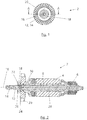
- FIG. 1 shows an end view of the armature 2. From the center inside radially outward, the drive section 12 rotates during operation of the hand tool around an axis 16 of the armature shaft 10.
- the armature shaft 10 is rotatably supported at least by a ball bearing 18 against components of the electric hand tool, not shown.
- a fan wheel 20 is provided on the package section 8 of the armature shaft 10.
- FIG. 2 shows a sectional view taken along the line AA FIG. 1 , In the image plane on the left, the drive section 12 of the armature shaft 10, the pinion 14 to connect the armature 2 with a transmission component of the electric power tool.
- this On the end facing away from the pinion 14 of the drive section 12, this has a pin 22 with, for example, not part of the claimed invention, round cross section.
- the pin 22 of the drive portion 12 is inserted into a recess 24 in the end face of the package section 8 of the armature shaft 10 and fixed in the exemplary embodiment shown by an adhesive bond therein, whereby package section 8 and drive section 12 are permanently connected to each other and non-rotatably.
- the ball bearing 18 is arranged, which supports the armature shaft 10 rotatably.
- the ball bearing 18 forms a connecting sleeve 26, the package section 8 and drive section 12 additionally defines each other.
- the fan 20 is arranged rotatably on the package section 8 of the armature shaft 10. During operation of the hand tool, the fan 20 rotates the armature shaft 10 and cools with the air flow generated thereby the passage ventilated electric motor.
- the fan 20 is partially against the metal surface of the package section 8 and partially on a plastic layer 28, which covers the package section 8 of the armature shaft 10 partially.
- the laminated core 4 In the image plane further to the right connects to the fan 20, the laminated core 4 with the armature winding.
- the laminated core 4 is pressed onto the plastic layer 28 of the package section 8 of the armature shaft 10 and thereby rotatably connected to the armature shaft 10.
- the plastic layer 28 also isolates the package section 8 with respect to the laminated core 4.
- a stator of the electric motor is arranged in the electric hand tool device (not shown).
- FIG. 3 shows the package section 8 of the armature shaft 10 without plastic layer 28.
- knurls 30 are introduced, which facilitate a subsequent connection of the plastic layer 28 with the package section 8.
- the recess 24 is inserted into the package section 8.
- This is complementary to the pin 22 of the drive section 12 of the armature shaft 10 is formed and has, for example, not part of the claimed invention, a round cross-section.
- FIG. 4 shows the drive portion 12 of the armature shaft 10 having the pinion 14 at the transmission-side end and the pin 22 at the other end.
Landscapes
- Engineering & Computer Science (AREA)
- Power Engineering (AREA)
- Connection Of Motors, Electrical Generators, Mechanical Devices, And The Like (AREA)
- Manufacture Of Motors, Generators (AREA)
- Iron Core Of Rotating Electric Machines (AREA)
Description
- Die Erfindung betrifft einen Anker für ein Elektrohandwerkzeuggerät mit einem Blechpaket, einem Kommutator und einer um eine Achse rotierbaren Ankerwelle, die getriebeseitig einen ein Ritzel umfassenden und mit einer Getriebekomponente zusammenwirkenden Antriebsabschnitt und einen Paketabschnitt aufweist, an dem zumindest das Blechpaket angeordnet ist. Sie betrifft ferner ein Elektrohandwerkzeuggerät mit einem einen solchen Anker aufweisenden Elektromotor.
- Es ist bekannt, in der Motorenproduktion für Elektrohandwerkzeuggeräte eine Vielzahl von unterschiedlichen Ankern herzustellen und vorzuhalten, die die gleichen Wickeldaten und Paketlängen aufweisen, sich jedoch hinsichtlich der Gestaltung der Ritzel unterscheiden.
- Die Elektrohandwerkzeuggeräte besitzen, abhängig von der jeweils konkreten Ausführungsform als Bohrmaschine, Stichsäge, Winkelschleifer oder dergleichen, unterschiedliche Getriebe, wodurch sich die den jeweiligen Elektrohandwerkzeuggeräten zugeordneten Anker in ihren Ritzeln voneinander unterscheiden.
- Um die Vielzahl unterschiedlicher Anker voneinander unterscheiden zu können werden ihnen Losnummern zugeordnet, wobei Anker mit gleichen Ritzeln, gleiche Losnummern besitzen.
- Bei den bekannten Ankern werden die Ritzel auf einer weichen Ankerwelle aufgebaut und anschließend einem Härte- und Richtprozess unterzogen.
- Die Anker einer Losnummer werden entsprechend der benötigten Stückzahl der konkreten Ausführungsform des Elektrohandwerkzeuggeräts gefertigt und die fertigende Maschine danach auf die Produktion eines anderen, eine andere Losnummer aufweisenden Ankers umgestellt. Dies erweist sich als zeitaufwendig und kostenintensiv.
- Um die Losgrößen im Zuge eines Fertigungsprozesses zu erhöhen, können Anker einer Losnummer unabhängig von der benötigten Stückzahl der konkreten Ausführungsform gefertigt werden und die überschüssigen Anker bevorratet werden, was Lagerraum erfordert und ebenfalls kostenintensiv ist. Stand der Technik ist
EP 1 353 433 A2 undDE 1 513 791 . - Aufgabe der Erfindung ist es, einen Anker vorzuschlagen, der die genannten Probleme reduziert.
- Die Aufgabe wird durch einen im unabhängigen Anspruch 1 definierten erfindungsgemäßen Anker gelöst, bei dem der Antriebsabschnitt und der Paketabschnitt der Ankerwelle aus separaten Baulteilen gebildet sind, die unlösbar und drehfest miteinander verbunden sind. Hierdurch kann eine hohe Stückzahl an Ankerwellen mit hohen Losgrößen gefertigt werden, die in unterschiedlichen konkreten Ausführungsformen des Elektrohandwerkzeuggeräts verwendbar sind, indem jeweils ein spezifischer Antriebsabschnitt erst in der Montagephase des Elektromotors an den Paketabschnitt der Ankerwelle angefügt wird.
- Ferner entfallen der Härte- und Richtprozess, da das Ritzel des Antriebsabschnitts nicht auf einer weichen Ankerwelle aufgebaut werden muss.
- Weitere Ausgestaltungsformen der Erfindung sind in den abhängigen Ansprüchen 2 - 9 definiert.
- Es erweist sich als vorteilhaft, dass der Antriebsabschnitt und der Paketabschnitt durch eine formschlüssige Verbindung unlösbar und drehfest miteinander verbunden sind. Hierdurch wird auf einfache Weise eine drehfeste Verbindung der beiden Abschnitte erreicht.
- Die Erfindung sieht vor, dass der Paketabschnitt stirnseitig an seinem dem Antriebsabschnitt zugewandten Ende eine Ausnehmung, insbesondere ein Sackloch, aufweist, in die ein in axialer Richtung erstreckter Zapfen am dem Ritzel abgewandten Ende des Antriebsabschnitts einführbar ist. Zapfen und Ausnehmung sind komplementär zueinander ausgebildet. Da beide Abschnitte durch einen Formschluss miteinander verbunden werden erweist sich ein polygonaler Querschnitt von Zapfen und Ausnehmung als zweckmäßig. Antriebsabschnitt und Paketabschnitt werden beim Fügen zueinander zentriert.
- In Weiterbildung letztgenannten Erfindungsgedankens erweist es sich von Vorteil, wenn zwischen der Ausnehmung am Paketabschnitt und dem Zapfen des Antriebsabschnitts ein in axialer Richtung erstreckter Spalt ausgebildet ist, der in radialer Richtung eine Breite von 0,03 mm bis 0,25 mm, bevorzugt 0,05 mm bis 0,2 mm, weiter bevorzugt 0,08 bis 0,15 mm, weiter bevorzugt 0,1 mm umfasst. Wenn die beiden Abschnitte beispielsweise durch eine Klebeverbindung aneinander festgelegt werden dient der Spalt als Klebespalt zum Aufnehmen bzw. Ablaufen von Klebstoff.
- Erfindungsgemäss ist zusätzlich eine Verbindungshülse vorgesehen, die den Antriebsabschnitt und den Paketabschnitt aneinander festlegt und/oder eine Führung für den Antriebsabschnitt und den Paketabschnitt bildet.
- Die Verbindungshülse kann durch ein zusätzliches Bauteil realisiert werden. Allerdings erweist es sich als vorteilhaft, wenn der Anker mindestens ein die Ankerwelle drehbar lagerndes Kugellager aufweist, welches die Verbindungshülse bildet. Dadurch wird auf ein ohnehin schon vorhandenes hochgenaues Bauteil zurückgegriffen und somit die Zahl der einzelnen Bauteile des Ankers nicht erhöht.
- Darüber hinaus erweist es sich als vorteilhaft, wenn an dem Paketabschnitt der Ankerwelle zusätzlich der Kommutator und ein Lüfterrad angeordnet sind.
- Vorzugsweise ist das Lüfterrad bezüglich des Blechpakets auf der dem Antriebsabschnitt zugewandten Seite des Paketabschnitts, und der Kommutator ist bezüglich des Blechpakets auf der dem Antriebsabschnitt abgewandten Seite des Paketabschnitts angeordnet.
- Schließlich weist bei einer bevorzugten Ausführungsform der Erfindung der Paketabschnitt der Ankerwelle zumindest bereichsweise eine Kunststoffschicht auf, auf die das Blechpaket aufgepresst ist. Hierdurch wird eine elektrische Isolation zwischen Blechpaket und Paketabschnitt der Ankerwelle realisiert, und die drehfeste Verankerung des Blechpakets auf der Ankerwelle ist einfacher herstellbar.
- Die Aufgabe wird darüber hinaus von einem Elektrohandwerkzeuggerät mit einem Anker gelöst, bei dem der Anker nach einem der Ansprüche 1 bis 8 ausgebildet ist.
- Weitere Merkmale, Einzelheiten und Vorteile der Erfindung ergeben sich aus den beigefügten Patentansprüchen und der zeichnerischen Darstellung und nachfolgenden Beschreibung einer Ausführungsform der Erfindung. In der Zeichnung zeigen:
- Figur 1
- eine Stirnansicht eines erfindungsgemäßen Ankers;
- Figur 2
- eine Schnittansicht des Ankers gemäß
Figur 1 entlang der Linie AA; - Figur 3
- eine perspektivische Ansicht eines Paketabschnitts des Ankers gemäß
Figur 1 ; - Figur 4
- eine perspektivische Ansicht eines Antriebsabschnitts des Ankers gemäß
Figur 1 . - Die
Figuren 1 und 2 zeigen einen insgesamt mit dem Bezugszeichen 2 versehenen Anker für ein Elektrohandwerkzeuggerät. Der Anker 2 umfasst ein Blechpaket 4 und einen Kommutator 6, die beide an einem Paketabschnitt 8 einer Ankerwelle 10 angeordnet, insbesondere aufgepresst, sind. Die Ankerwelle 10 umfasst ferner einen Antriebsabschnitt 12, der getriebeseitig ein Ritzel 14 besitzt und mit einer Getriebekomponente des Elektrohandwerkzeuggeräts (nicht dargestellt) in Antriebsverbindung gebracht wird. - Antriebsabschnitt 12 und Paketabschnitt 8 der Ankerwelle 10 sind aus separaten Bauteilen gebildet und unlösbar und drehfest miteinander verbunden.
-
Figur 1 zeigt eine Stirnsicht des Ankers 2. Vom Zentrum innen nach radial außen betrachtet dreht sich der Antriebsabschnitt 12 beim Betrieb des Handwerkzeuggeräts um eine Achse 16 der Ankerwelle 10. Die Ankerwelle 10 ist dabei zumindest durch ein Kugellager 18 drehbar gegenüber Komponenten des nicht dargestellten Elektrohandwerkzeuggeräts gelagert. Um den Anker 2 vor Überhitzung zu schützen ist am Paketabschnitt 8 der Ankerwelle 10 ein Lüfterrad 20 vorgesehen. -
Figur 2 zeigt eine Schnittansicht entlang der Linie AA ausFigur 1 . In der Bildebene links weist der Antriebsabschnitt 12 der Ankerwelle 10 das Ritzel 14 auf, um den Anker 2 mit einer Getriebekomponente des Elektrohandwerkzeuggeräts zu verbinden. - Auf der dem Ritzel 14 abgewandten Ende des Antriebsabschnitts 12 weist dieser einen Zapfen 22 mit beispielsweise, nicht Teil der beanspruchten Erfindung, rundem Querschnitt auf. Mit dem Zapfen 22 ist der Antriebsabschnitt 12 in eine Ausnehmung 24 in der Stirnseite des Paketabschnitts 8 der Ankerwelle 10 eingesteckt und bei dem beispielhaft gezeigten Ausführungsbeispiel durch eine Klebeverbindung darin festgelegt, wodurch Paketabschnitt 8 und Antriebsabschnitt 12 unlösbar und drehfest miteinander verbunden sind.
- Auf Höhe des Zapfens 22 des Antriebsabschnitts 12 und der Ausnehmung 24 des Paketabschnitts 8 ist das Kugellager 18 angeordnet, das die Ankerwelle 10 drehbar lagert. Zudem bildet das Kugellager 18 eine Verbindungshülse 26, die Paketabschnitt 8 und Antriebsabschnitt 12 zusätzlich aneinander festlegt.
- In der Bildebene rechts vom Kugellager 18 ist das Lüfterrad 20 am Paketabschnitt 8 der Ankerwelle 10 drehfest angeordnet. Beim Betrieb des Handwerkzeuggeräts dreht sich das Lüfterrad 20 mit der Ankerwelle 10 und kühlt mit dem hierdurch erzeugten Luftstrom den durchzugsbelüfteten Elektromotor.
- Bei dem in
Figur 2 gezeigtem Ausführungsbeispiel des Ankers 2 liegt das Lüfterrad 20 teilweise an der metallenen Oberfläche des Paketabschnitts 8 und teilweise an einer Kunststoffschicht 28 an, die den Paketabschnitt 8 der Ankerwelle 10 bereichsweise bedeckt. - In Bildebene weiter rechts schließt sich an das Lüfterrad 20 das Blechpaket 4 mit der Ankerwicklung an. Das Blechpaket 4 ist auf die Kunststoffschicht 28 des Paketabschnitts 8 der Ankerwelle 10 aufgepresst und dadurch drehfest mit der Ankerwelle 10 verbunden. Die Kunststoffschicht 28 isoliert zudem den Paketabschnitt 8 gegenüber dem Blechpaket 4. Um das Blechpaket herum ist im Elektrohandwerkzeuggerät ein Stator des Elektromotors angeordnet (nicht dargestellt).
-
Figur 3 zeigt den Paketabschnitt 8 der Ankerwelle 10 ohne Kunststoffschicht 28. Auf der Mantelfläche des Paketabschnitts sind Rändel 30 eingebracht, die ein späteres Verbinden der Kunststoffschicht 28 mit dem Paketabschnitt 8 vereinfachen. - Auf der dem Antriebsabschnitt 12 zugewandten Stirnseite des Paketabschnitts 8 der Ankerwelle 10 ist die Ausnehmung 24 in den Paketabschnitt 8 eingebracht. Diese ist komplementär zum Zapfen 22 des Antriebabschnitts 12 der Ankerwelle 10 ausgebildet und weist als Beispiel, nicht Teil der beanspruchten Erfindung, einen runden Querschnitt auf.
-
Figur 4 zeigt den Antriebsabschnitt 12 der Ankerwelle 10, der am getriebeseitigen Ende das Ritzel 14 und an dem anderen Ende den Zapfen 22 aufweist.
Claims (9)
- Anker (2) für ein Elektrohandwerkzeuggerät mit einem Blechpaket (4), einem Kommutator (6) und einer um eine Achse (16) rotierbaren Ankerwelle (10), die getriebeseitig einen ein Ritzel (14) umfassenden und mit einer Getriebekomponente zusammenwirkenden Antriebsabschnitt (12) und einen Paketabschnitt (8) aufweist, an dem zumindest das Blechpaket (4) angeordnet ist, wobei der Antriebsabschnitt (12) und der Paketabschnitt (8) der Ankerwelle (10) aus separaten Bauteilen gebildet sind, die unlösbar und drehfest miteinander verbunden sind, dadurch gekennzeichnet, dass zusätzlich eine Verbindungshülse (26) vorgesehen ist, die den Antriebsabschnitt (12) und den Paketabschnitt (8) aneinander festlegt und/oder eine Führung für den Antriebsabschnitt (12) und den Paketabschnitt (8) bildet, und wobei der Antriebsabschnitt (12) und der Paketabschnitt (9) durch eine formschlüssige Verbindung miteinander verbunden sind und der Paketabschnitt (8) stirnseitig an seinem dem Antriebsabschnitt (12) zugewandten Ende eine Ausnehmung (24) aufweist, in die ein in axialer Richtung erstreckter Zapfen (22) am Ritzel (14) abgewandten Ende des Antriebsabschnitts (12) eingreift, wobei die Ausnehmung (24) und der Zapfen (22) einen polygonalen Querschnitt aufweisen.
- Anker (2) nach Anspruch 1, dadurch gekennzeichnet, dass der Antriebsabschnitt (12) und der Paketabschnitt (8) zusätzlich durch eine reibschlüssige Verbindung und/oder zusätzlich durch eine Klebeverbindung unlösbar und drehfest miteinander verbunden sind.
- Anker (2) nach Anspruch 1 oder 2, dadurch gekennzeichnet, dass die Ausnehmung (24)als Sackloch ausgebildet ist.
- Anker (2) nach einem oder mehreren der vorhergehenden Ansprüche, dadurch gekennzeichnet, dass zwischen der Ausnehmung (24) am Paketabschnitt (8) und dem Zapfen des Antriebsabschnitts (12) ein in axialer Richtung erstreckter Spalt ausgebildet ist, der in radialer Richtung eine Breite von 0,03 mm bis 0,25 mm, bevorzugt 0,05 mm bis 0,2 mm, weiter bevorzugt 0,08 bis 0,15 mm, weiter bevorzugt 0,1 mm umfasst.
- Anker (2) nach Anspruch 1, dadurch gekennzeichnet, dass er ein die Ankerwelle (10) drehbar lagerndes Kugellager (18) aufweist, welches die Verbindungshülse (26) bildet.
- Anker (2) nach einem oder mehreren der vorhergehenden Ansprüche, dadurch gekennzeichnet, dass an dem Paketabschnitt (8) der Ankerwelle (10) zusätzlich der Kommutator (6) und ein Lüfterrad (20) angeordnet sind.
- Anker (2) nach Anspruch 6, dadurch gekennzeichnet, dass das Lüfterrad (20) bezüglich des Blechpakets (4) auf der dem Antriebsabschnitt (12) zugewandten Seite des Paketabschnitts (8) und der Kommutator (6) bezüglich des Blechpakets (4) auf der dem Antriebsabschnitt (12) abgewandten Seite des Paketabschnitts (8) angeordnet sind.
- Anker (2) nach einem oder mehreren der vorhergehenden Ansprüche, dadurch gekennzeichnet, dass der Paketabschnitt (8) der Ankerwelle (10) zumindest bereichsweise eine Kunststoffschicht (28) aufweist, auf die das Blechpaket (4) aufgepresst ist.
- Elektrohandwerkzeuggerät mit einem Anker (2), dadurch gekennzeichnet, dass er nach einem der Ansprüche 1 bis 8 ausgebildet ist.
Applications Claiming Priority (2)
| Application Number | Priority Date | Filing Date | Title |
|---|---|---|---|
| DE102010006345A DE102010006345A1 (de) | 2010-01-30 | 2010-01-30 | Anker für ein Elektrohandwerkzeuggerät |
| PCT/EP2011/050968 WO2011092156A2 (de) | 2010-01-30 | 2011-01-25 | Anker für ein elektrohandwerkzeuggerät |
Publications (2)
| Publication Number | Publication Date |
|---|---|
| EP2499723A2 EP2499723A2 (de) | 2012-09-19 |
| EP2499723B1 true EP2499723B1 (de) | 2019-01-16 |
Family
ID=44275663
Family Applications (1)
| Application Number | Title | Priority Date | Filing Date |
|---|---|---|---|
| EP11701106.4A Not-in-force EP2499723B1 (de) | 2010-01-30 | 2011-01-25 | Anker für ein elektrohandwerkzeuggerät |
Country Status (3)
| Country | Link |
|---|---|
| EP (1) | EP2499723B1 (de) |
| DE (1) | DE102010006345A1 (de) |
| WO (1) | WO2011092156A2 (de) |
Families Citing this family (2)
| Publication number | Priority date | Publication date | Assignee | Title |
|---|---|---|---|---|
| DE202011003472U1 (de) | 2011-03-03 | 2011-05-05 | Bürkert Werke GmbH | Magnetventil |
| DE102018116752A1 (de) | 2018-07-11 | 2020-01-16 | Metabowerke Gmbh | Elektrohandwerkzeuggerät |
Family Cites Families (5)
| Publication number | Priority date | Publication date | Assignee | Title |
|---|---|---|---|---|
| US3413498A (en) * | 1965-08-09 | 1968-11-26 | Rockwell Mfg Co | Electrically powered hand tool |
| DE1513791A1 (de) * | 1966-02-24 | 1969-07-03 | Licentia Gmbh | Elektromotorisch angetriebenes Handwerkzeug |
| DE10005211B4 (de) * | 2000-02-05 | 2007-11-22 | Metabowerke Gmbh | Elektrohandwerkzeug-Elektromotor |
| DE10215493A1 (de) * | 2002-04-09 | 2003-10-23 | Atlas Copco Electric Tools | Elektromotor |
| DE102007043527A1 (de) * | 2007-09-12 | 2009-03-19 | Robert Bosch Gmbh | Elektromotor |
-
2010
- 2010-01-30 DE DE102010006345A patent/DE102010006345A1/de not_active Ceased
-
2011
- 2011-01-25 WO PCT/EP2011/050968 patent/WO2011092156A2/de not_active Ceased
- 2011-01-25 EP EP11701106.4A patent/EP2499723B1/de not_active Not-in-force
Non-Patent Citations (1)
| Title |
|---|
| None * |
Also Published As
| Publication number | Publication date |
|---|---|
| EP2499723A2 (de) | 2012-09-19 |
| WO2011092156A3 (de) | 2011-10-13 |
| DE102010006345A1 (de) | 2011-08-04 |
| WO2011092156A2 (de) | 2011-08-04 |
Similar Documents
| Publication | Publication Date | Title |
|---|---|---|
| WO2020099048A1 (de) | Stützeinrichtung für einen rotor einer fremderregten innenläufer-synchronmaschine bestehend aus einem stützring und einer sternscheibe | |
| EP2907226B1 (de) | Rotoranordnung für eine elektrische maschine | |
| DE102013217021A1 (de) | Bürstenloser Motor, Stator, Herstellungsverfahren für einen Stator und Herstellungsverfahren für einen bürstenlosen Motor | |
| DE102018213609A1 (de) | Rotor für eine elektrische Maschine | |
| DE102020212922B4 (de) | Stator für eine elektrische Maschine, Verfahren zur Herstellung eines Stators und elektrische Maschine | |
| DE102019208099A1 (de) | Rotor für eine elektrische Maschine, Verfahren zur Herstellung eines Rotors und elektrische Maschine mit einem Rotor | |
| DE102016010224A1 (de) | Elektrische Maschine für ein Kraftfahrzeug, Herstellungsverfahren und Stanzwerkzeug | |
| EP2876789B1 (de) | Verfahren zur Herstellung eines Rotors | |
| EP3479459B1 (de) | Rotor mit rotorschrägung für eine elektrische maschine und elektromotor für den fahrantrieb eines kraftfahrzeugs | |
| WO2019121001A1 (de) | Rotor- oder statoranordnung mit permanentmagneten | |
| DE60215147T2 (de) | Elektrische Servolenkung für ein Fahrzeug | |
| DE102010006345A1 (de) | Anker für ein Elektrohandwerkzeuggerät | |
| WO2021239177A1 (de) | Blechpaketsatz sowie rotor mit auf rotorwelle aufgestecktem blechpaketsatz | |
| WO2011088862A1 (de) | Rotor einer elektrischen maschine und verfahren zur herstellung eines rotors einer elektrischen maschine | |
| EP3035497B1 (de) | Karusselltür | |
| DE102021209100A1 (de) | Welle-Nabe-Verbund sowie elektrische Maschine mit einem solchen | |
| DE3050453C2 (de) | Rotor einer schnellaufenden elektrischen Maschine | |
| DE102021205713A1 (de) | Rotor für eine elektrische Maschine | |
| DE102013206121A1 (de) | Synchrongenerator-Polpaket | |
| DE102013019779A1 (de) | Stator für eine elektrische Maschine | |
| DE102021214306B4 (de) | Rotor einer fremderregten elektrischen Maschine, elektrische Maschine, und Kraftfahrzeug | |
| DE102006034120A1 (de) | Anker mit Isolierlamelle sowie Elektromotor | |
| DE102023212371A1 (de) | Stator für eine elektrische Maschine und elektrische Maschine | |
| DE102023209817A1 (de) | Rotor mit vergrabenen Magneten, Traktionsantrieb, Kraftfahrzeug und Verfahren zur Herstellung eines Rotors | |
| WO2007033639A1 (de) | Stator für einen elektromotor und verfahren zur herstellung |
Legal Events
| Date | Code | Title | Description |
|---|---|---|---|
| PUAI | Public reference made under article 153(3) epc to a published international application that has entered the european phase |
Free format text: ORIGINAL CODE: 0009012 |
|
| 17P | Request for examination filed |
Effective date: 20120510 |
|
| AK | Designated contracting states |
Kind code of ref document: A2 Designated state(s): AL AT BE BG CH CY CZ DE DK EE ES FI FR GB GR HR HU IE IS IT LI LT LU LV MC MK MT NL NO PL PT RO RS SE SI SK SM TR |
|
| DAX | Request for extension of the european patent (deleted) | ||
| STAA | Information on the status of an ep patent application or granted ep patent |
Free format text: STATUS: EXAMINATION IS IN PROGRESS |
|
| 17Q | First examination report despatched |
Effective date: 20161223 |
|
| GRAP | Despatch of communication of intention to grant a patent |
Free format text: ORIGINAL CODE: EPIDOSNIGR1 |
|
| STAA | Information on the status of an ep patent application or granted ep patent |
Free format text: STATUS: GRANT OF PATENT IS INTENDED |
|
| INTG | Intention to grant announced |
Effective date: 20180731 |
|
| GRAS | Grant fee paid |
Free format text: ORIGINAL CODE: EPIDOSNIGR3 |
|
| GRAA | (expected) grant |
Free format text: ORIGINAL CODE: 0009210 |
|
| STAA | Information on the status of an ep patent application or granted ep patent |
Free format text: STATUS: THE PATENT HAS BEEN GRANTED |
|
| AK | Designated contracting states |
Kind code of ref document: B1 Designated state(s): AL AT BE BG CH CY CZ DE DK EE ES FI FR GB GR HR HU IE IS IT LI LT LU LV MC MK MT NL NO PL PT RO RS SE SI SK SM TR |
|
| REG | Reference to a national code |
Ref country code: GB Ref legal event code: FG4D Free format text: NOT ENGLISH |
|
| REG | Reference to a national code |
Ref country code: CH Ref legal event code: EP |
|
| REG | Reference to a national code |
Ref country code: IE Ref legal event code: FG4D Free format text: LANGUAGE OF EP DOCUMENT: GERMAN |
|
| REG | Reference to a national code |
Ref country code: AT Ref legal event code: REF Ref document number: 1090444 Country of ref document: AT Kind code of ref document: T Effective date: 20190215 |
|
| REG | Reference to a national code |
Ref country code: DE Ref legal event code: R096 Ref document number: 502011015292 Country of ref document: DE |
|
| REG | Reference to a national code |
Ref country code: NL Ref legal event code: MP Effective date: 20190116 |
|
| REG | Reference to a national code |
Ref country code: LT Ref legal event code: MG4D |
|
| PG25 | Lapsed in a contracting state [announced via postgrant information from national office to epo] |
Ref country code: NL Free format text: LAPSE BECAUSE OF FAILURE TO SUBMIT A TRANSLATION OF THE DESCRIPTION OR TO PAY THE FEE WITHIN THE PRESCRIBED TIME-LIMIT Effective date: 20190116 |
|
| PG25 | Lapsed in a contracting state [announced via postgrant information from national office to epo] |
Ref country code: FI Free format text: LAPSE BECAUSE OF FAILURE TO SUBMIT A TRANSLATION OF THE DESCRIPTION OR TO PAY THE FEE WITHIN THE PRESCRIBED TIME-LIMIT Effective date: 20190116 Ref country code: SE Free format text: LAPSE BECAUSE OF FAILURE TO SUBMIT A TRANSLATION OF THE DESCRIPTION OR TO PAY THE FEE WITHIN THE PRESCRIBED TIME-LIMIT Effective date: 20190116 Ref country code: LT Free format text: LAPSE BECAUSE OF FAILURE TO SUBMIT A TRANSLATION OF THE DESCRIPTION OR TO PAY THE FEE WITHIN THE PRESCRIBED TIME-LIMIT Effective date: 20190116 Ref country code: ES Free format text: LAPSE BECAUSE OF FAILURE TO SUBMIT A TRANSLATION OF THE DESCRIPTION OR TO PAY THE FEE WITHIN THE PRESCRIBED TIME-LIMIT Effective date: 20190116 Ref country code: PL Free format text: LAPSE BECAUSE OF FAILURE TO SUBMIT A TRANSLATION OF THE DESCRIPTION OR TO PAY THE FEE WITHIN THE PRESCRIBED TIME-LIMIT Effective date: 20190116 Ref country code: PT Free format text: LAPSE BECAUSE OF FAILURE TO SUBMIT A TRANSLATION OF THE DESCRIPTION OR TO PAY THE FEE WITHIN THE PRESCRIBED TIME-LIMIT Effective date: 20190516 Ref country code: NO Free format text: LAPSE BECAUSE OF FAILURE TO SUBMIT A TRANSLATION OF THE DESCRIPTION OR TO PAY THE FEE WITHIN THE PRESCRIBED TIME-LIMIT Effective date: 20190416 |
|
| PG25 | Lapsed in a contracting state [announced via postgrant information from national office to epo] |
Ref country code: LV Free format text: LAPSE BECAUSE OF FAILURE TO SUBMIT A TRANSLATION OF THE DESCRIPTION OR TO PAY THE FEE WITHIN THE PRESCRIBED TIME-LIMIT Effective date: 20190116 Ref country code: RS Free format text: LAPSE BECAUSE OF FAILURE TO SUBMIT A TRANSLATION OF THE DESCRIPTION OR TO PAY THE FEE WITHIN THE PRESCRIBED TIME-LIMIT Effective date: 20190116 Ref country code: HR Free format text: LAPSE BECAUSE OF FAILURE TO SUBMIT A TRANSLATION OF THE DESCRIPTION OR TO PAY THE FEE WITHIN THE PRESCRIBED TIME-LIMIT Effective date: 20190116 Ref country code: GR Free format text: LAPSE BECAUSE OF FAILURE TO SUBMIT A TRANSLATION OF THE DESCRIPTION OR TO PAY THE FEE WITHIN THE PRESCRIBED TIME-LIMIT Effective date: 20190417 Ref country code: IS Free format text: LAPSE BECAUSE OF FAILURE TO SUBMIT A TRANSLATION OF THE DESCRIPTION OR TO PAY THE FEE WITHIN THE PRESCRIBED TIME-LIMIT Effective date: 20190516 Ref country code: BG Free format text: LAPSE BECAUSE OF FAILURE TO SUBMIT A TRANSLATION OF THE DESCRIPTION OR TO PAY THE FEE WITHIN THE PRESCRIBED TIME-LIMIT Effective date: 20190416 |
|
| REG | Reference to a national code |
Ref country code: CH Ref legal event code: PL |
|
| PG25 | Lapsed in a contracting state [announced via postgrant information from national office to epo] |
Ref country code: LU Free format text: LAPSE BECAUSE OF NON-PAYMENT OF DUE FEES Effective date: 20190125 |
|
| REG | Reference to a national code |
Ref country code: BE Ref legal event code: MM Effective date: 20190131 Ref country code: DE Ref legal event code: R097 Ref document number: 502011015292 Country of ref document: DE |
|
| REG | Reference to a national code |
Ref country code: IE Ref legal event code: MM4A |
|
| PG25 | Lapsed in a contracting state [announced via postgrant information from national office to epo] |
Ref country code: DK Free format text: LAPSE BECAUSE OF FAILURE TO SUBMIT A TRANSLATION OF THE DESCRIPTION OR TO PAY THE FEE WITHIN THE PRESCRIBED TIME-LIMIT Effective date: 20190116 Ref country code: EE Free format text: LAPSE BECAUSE OF FAILURE TO SUBMIT A TRANSLATION OF THE DESCRIPTION OR TO PAY THE FEE WITHIN THE PRESCRIBED TIME-LIMIT Effective date: 20190116 Ref country code: RO Free format text: LAPSE BECAUSE OF FAILURE TO SUBMIT A TRANSLATION OF THE DESCRIPTION OR TO PAY THE FEE WITHIN THE PRESCRIBED TIME-LIMIT Effective date: 20190116 Ref country code: CZ Free format text: LAPSE BECAUSE OF FAILURE TO SUBMIT A TRANSLATION OF THE DESCRIPTION OR TO PAY THE FEE WITHIN THE PRESCRIBED TIME-LIMIT Effective date: 20190116 Ref country code: IT Free format text: LAPSE BECAUSE OF FAILURE TO SUBMIT A TRANSLATION OF THE DESCRIPTION OR TO PAY THE FEE WITHIN THE PRESCRIBED TIME-LIMIT Effective date: 20190116 Ref country code: MC Free format text: LAPSE BECAUSE OF FAILURE TO SUBMIT A TRANSLATION OF THE DESCRIPTION OR TO PAY THE FEE WITHIN THE PRESCRIBED TIME-LIMIT Effective date: 20190116 Ref country code: SK Free format text: LAPSE BECAUSE OF FAILURE TO SUBMIT A TRANSLATION OF THE DESCRIPTION OR TO PAY THE FEE WITHIN THE PRESCRIBED TIME-LIMIT Effective date: 20190116 Ref country code: AL Free format text: LAPSE BECAUSE OF FAILURE TO SUBMIT A TRANSLATION OF THE DESCRIPTION OR TO PAY THE FEE WITHIN THE PRESCRIBED TIME-LIMIT Effective date: 20190116 |
|
| PLBE | No opposition filed within time limit |
Free format text: ORIGINAL CODE: 0009261 |
|
| STAA | Information on the status of an ep patent application or granted ep patent |
Free format text: STATUS: NO OPPOSITION FILED WITHIN TIME LIMIT |
|
| PG25 | Lapsed in a contracting state [announced via postgrant information from national office to epo] |
Ref country code: BE Free format text: LAPSE BECAUSE OF NON-PAYMENT OF DUE FEES Effective date: 20190131 Ref country code: SM Free format text: LAPSE BECAUSE OF FAILURE TO SUBMIT A TRANSLATION OF THE DESCRIPTION OR TO PAY THE FEE WITHIN THE PRESCRIBED TIME-LIMIT Effective date: 20190116 |
|
| 26N | No opposition filed |
Effective date: 20191017 |
|
| PG25 | Lapsed in a contracting state [announced via postgrant information from national office to epo] |
Ref country code: LI Free format text: LAPSE BECAUSE OF NON-PAYMENT OF DUE FEES Effective date: 20190131 Ref country code: CH Free format text: LAPSE BECAUSE OF NON-PAYMENT OF DUE FEES Effective date: 20190131 |
|
| PG25 | Lapsed in a contracting state [announced via postgrant information from national office to epo] |
Ref country code: IE Free format text: LAPSE BECAUSE OF NON-PAYMENT OF DUE FEES Effective date: 20190125 |
|
| PG25 | Lapsed in a contracting state [announced via postgrant information from national office to epo] |
Ref country code: SI Free format text: LAPSE BECAUSE OF FAILURE TO SUBMIT A TRANSLATION OF THE DESCRIPTION OR TO PAY THE FEE WITHIN THE PRESCRIBED TIME-LIMIT Effective date: 20190116 |
|
| REG | Reference to a national code |
Ref country code: AT Ref legal event code: MM01 Ref document number: 1090444 Country of ref document: AT Kind code of ref document: T Effective date: 20190125 |
|
| PG25 | Lapsed in a contracting state [announced via postgrant information from national office to epo] |
Ref country code: TR Free format text: LAPSE BECAUSE OF FAILURE TO SUBMIT A TRANSLATION OF THE DESCRIPTION OR TO PAY THE FEE WITHIN THE PRESCRIBED TIME-LIMIT Effective date: 20190116 |
|
| PG25 | Lapsed in a contracting state [announced via postgrant information from national office to epo] |
Ref country code: AT Free format text: LAPSE BECAUSE OF NON-PAYMENT OF DUE FEES Effective date: 20190125 |
|
| PG25 | Lapsed in a contracting state [announced via postgrant information from national office to epo] |
Ref country code: MT Free format text: LAPSE BECAUSE OF FAILURE TO SUBMIT A TRANSLATION OF THE DESCRIPTION OR TO PAY THE FEE WITHIN THE PRESCRIBED TIME-LIMIT Effective date: 20190116 |
|
| PGFP | Annual fee paid to national office [announced via postgrant information from national office to epo] |
Ref country code: FR Payment date: 20210121 Year of fee payment: 11 |
|
| PG25 | Lapsed in a contracting state [announced via postgrant information from national office to epo] |
Ref country code: CY Free format text: LAPSE BECAUSE OF FAILURE TO SUBMIT A TRANSLATION OF THE DESCRIPTION OR TO PAY THE FEE WITHIN THE PRESCRIBED TIME-LIMIT Effective date: 20190116 |
|
| PGFP | Annual fee paid to national office [announced via postgrant information from national office to epo] |
Ref country code: GB Payment date: 20210122 Year of fee payment: 11 Ref country code: DE Payment date: 20210120 Year of fee payment: 11 |
|
| PG25 | Lapsed in a contracting state [announced via postgrant information from national office to epo] |
Ref country code: HU Free format text: LAPSE BECAUSE OF FAILURE TO SUBMIT A TRANSLATION OF THE DESCRIPTION OR TO PAY THE FEE WITHIN THE PRESCRIBED TIME-LIMIT; INVALID AB INITIO Effective date: 20110125 |
|
| PG25 | Lapsed in a contracting state [announced via postgrant information from national office to epo] |
Ref country code: MK Free format text: LAPSE BECAUSE OF FAILURE TO SUBMIT A TRANSLATION OF THE DESCRIPTION OR TO PAY THE FEE WITHIN THE PRESCRIBED TIME-LIMIT Effective date: 20190116 |
|
| REG | Reference to a national code |
Ref country code: DE Ref legal event code: R119 Ref document number: 502011015292 Country of ref document: DE |
|
| GBPC | Gb: european patent ceased through non-payment of renewal fee |
Effective date: 20220125 |
|
| PG25 | Lapsed in a contracting state [announced via postgrant information from national office to epo] |
Ref country code: GB Free format text: LAPSE BECAUSE OF NON-PAYMENT OF DUE FEES Effective date: 20220125 Ref country code: DE Free format text: LAPSE BECAUSE OF NON-PAYMENT OF DUE FEES Effective date: 20220802 |
|
| PG25 | Lapsed in a contracting state [announced via postgrant information from national office to epo] |
Ref country code: FR Free format text: LAPSE BECAUSE OF NON-PAYMENT OF DUE FEES Effective date: 20220131 |