EP2499050B1 - Improved packaging machine - Google Patents
Improved packaging machine Download PDFInfo
- Publication number
- EP2499050B1 EP2499050B1 EP10790675.2A EP10790675A EP2499050B1 EP 2499050 B1 EP2499050 B1 EP 2499050B1 EP 10790675 A EP10790675 A EP 10790675A EP 2499050 B1 EP2499050 B1 EP 2499050B1
- Authority
- EP
- European Patent Office
- Prior art keywords
- machine
- packaging
- packaging machine
- present
- welding
- Prior art date
- Legal status (The legal status is an assumption and is not a legal conclusion. Google has not performed a legal analysis and makes no representation as to the accuracy of the status listed.)
- Revoked
Links
Images

Classifications
-
- B—PERFORMING OPERATIONS; TRANSPORTING
- B65—CONVEYING; PACKING; STORING; HANDLING THIN OR FILAMENTARY MATERIAL
- B65B—MACHINES, APPARATUS OR DEVICES FOR, OR METHODS OF, PACKAGING ARTICLES OR MATERIALS; UNPACKING
- B65B31/00—Packaging articles or materials under special atmospheric or gaseous conditions; Adding propellants to aerosol containers
- B65B31/02—Filling, closing, or filling and closing, containers or wrappers in chambers maintained under vacuum or superatmospheric pressure or containing a special atmosphere, e.g. of inert gas
- B65B31/024—Filling, closing, or filling and closing, containers or wrappers in chambers maintained under vacuum or superatmospheric pressure or containing a special atmosphere, e.g. of inert gas specially adapted for wrappers or bags
-
- B—PERFORMING OPERATIONS; TRANSPORTING
- B65—CONVEYING; PACKING; STORING; HANDLING THIN OR FILAMENTARY MATERIAL
- B65B—MACHINES, APPARATUS OR DEVICES FOR, OR METHODS OF, PACKAGING ARTICLES OR MATERIALS; UNPACKING
- B65B51/00—Devices for, or methods of, sealing or securing package folds or closures; Devices for gathering or twisting wrappers, or necks of bags
- B65B51/10—Applying or generating heat or pressure or combinations thereof
-
- B—PERFORMING OPERATIONS; TRANSPORTING
- B65—CONVEYING; PACKING; STORING; HANDLING THIN OR FILAMENTARY MATERIAL
- B65B—MACHINES, APPARATUS OR DEVICES FOR, OR METHODS OF, PACKAGING ARTICLES OR MATERIALS; UNPACKING
- B65B61/00—Auxiliary devices, not otherwise provided for, for operating on sheets, blanks, webs, binding material, containers or packages
- B65B61/26—Auxiliary devices, not otherwise provided for, for operating on sheets, blanks, webs, binding material, containers or packages for marking or coding completed packages
Definitions
- the present invention refers to an improved packaging machine.
- Vacuum packaging machines are known in the art: in general, packaging through such machines occurs by introducing the product to be packaged inside an envelope made of plastic material or a vessel suitable for vacuum packaging, and by placing the envelope containing the product inside a decompression chamber composed of a tank and a basculating bell comprising elements adapted for welding the envelope or the vessel and for keeping vacuum inside such tank.
- Such machines are e.g. known from EP 10403 185 A1 . vacuum inside such tank.
- a suction cycle is started by means of a pump.
- the remaining pressure inside the vacuum chamber can reach 2 mBar absolute: at that time, welding is performed together with welding of the envelope containing the product by using the same pressure difference between the decompression chamber interior and the atmosphere through membranes connected to the welding bars of the basculating bell and to a solenoid valve.
- atmospheric air enters into the decompression chamber and the atmospheric pressure allows to completely adhere the envelope to the packaged product, at the same time guaranteeing welding of the package: in fact, should the package be opened or damaged, the envelope would not adhere any more to the packaged product, alerting the possible purchaser of the product.
- object of the present invention is solving the above prior art problems, by providing an improved packaging machine equipped with communication means connected to processing means and to printing means, such as for example a label-printing machine, that allows applying labels onto newly packaged products, such labels including, among other things, information related to traceability of the products themselves.
- an object of the present invention is providing an improved packaging machine equipped with access openings that allow a better access by an operator to the machine sides.
- Another object of the present invention is providing an improved packaging machine equipped with at least one window or hole suitable to allow the immediate and practical control of the oil level for a pump of such machine.
- Another object of the present invention is providing an improved packaging machine equipped with at least one lamellar transformer as replacement of the traditional transformer, allowing to obtain a more compact machine and to guarantee a better operating regularity.
- an object of the present invention is providing an improved packaging machine equipped with protecting means against overheating of the welding bars.
- an object of the present invention is providing an improved packaging machine equipped with means for optimally regulating the air speed when re-entering into the decompression chamber, in order not to impair the stability of the envelopes in favour of the final aesthetic result of the package.
- the improved packaging machine 1 is composed of a supporting and containing structure 3, obviously adapted to contain therein all functional members of the machine 1, that are substantially known in the art, and possibly to externally support at least one command and control panel 5 of the operation of the machine 1, such supporting and containing structure 3 comprising at least one decompression chamber 7 for a vacuum packaging of a product, for example inside an envelope made of plastic material or another suitable vessel, such chamber 7 being composed of at least one tank covered by at least one basculating bell 9 adapted for welding the open edges of such envelope, preferably through perimeter welding bars with which such bell is equipped.
- the packaging machine 1 is equipped with communication means connected to processing means and to printing means (suich as a printer or a label-printing machine).
- communication means can be at least one communication port of the RS-232 type, through which it is possible to take, from the machine, operating packaging data, such as packaging date, expiry date of the packaged product, operator code, batch number, packaging data (percentages of vacuum, gas, pressure, welding time, etc.) in order to be afterwards processed by such processing means and such printing means.
- the external printing means such as for example the label-printing machine
- the packaging machine 1 can be equipped with at least one housing seat 21 suitable for housing therein such printing means, and in particular the printer or the label-printing machine.
- the communication means are arranged next to such housing seat 21.
- the application then of the printing of an adhesive label integrated with the machine 1 according to the present invention is a major item to guarantee the packaging: in fact, once that suitable means of the machine 1 have detected the above operating packaging data, all or part of such data are transmitted to the processing means and to the printing means through the communication means; in particular, such data can be transmitted to the label-printing machine, which includes them on a printout on an adhesive label that will be applied onto the envelope containing the product. In this way, the warranty of the vacuum packaged product is not limited to its package, but is also given by the traceability of the product itself.
- the communication means can be made according to any technology, also of the wireless type, known in the art and suitable for such purpose.
- the supporting and containing structure 3 of the packaging machine 1 can comprise at least one first access opening 11, possibly covered by at least one protecting panel (not shown) that can be easily removed, such first access opening 11 being suitably arranged next to the connections 13 of the extending devices 14 for opening the basculating bell 9 inside the supporting and containing structure 3: the first access opening 11 therefore allows a better access by an operator on the sides of the machine 1 for maintenance and, in particular, allows replacing the extending devices 14 themselves without the need of lifting the heat-shrinking tank, thereby making such operation easier and quicker.
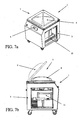
- the packaging machine 1 according to the present invention can be equipped with at least one suitable power card as replacement of the traditional electro-mechanical box present in packaging machines belonging to the prior art: advantageously therefore, with particular reference to Figures 3a , 4a , 5a , 6a and 7a , it is possible to note that the supporting and containing structure 3 of the packaging machine 1 according to the present invention can comprise at least one second access opening 15, also possibly covered by at least one protecting panel (not shown) that can be easily removed, such second access opening 15 being suitably arranged next to the power card arranged inside the supporting and containing structure 3: the second access opening 15 therefore allows a better access by an operator on the sides of the machine 1 for maintenance and, in particular, easily and quickly allows directly operating on the power card.
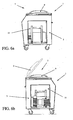
- the supporting and containing structure 3 of the packaging machine 1 can comprise at least one window or hole 17 arranged next to a visor of the pump placed inside the supporting and containing structure 3, such hole 17 being preferably arranged on a rear wall 19 of such supporting and containing structure 3 and being adapted to advantageously allow the immediate and practical check of the oil level of such pump without the need, by an operator, of accessing inside the machine 1.
- the packaging machine 1 according to the present invention can comprise at least one lamellar transformer as replacement of the traditional transformer used in known packaging machines: such lamellar transformer in fact advantageously confers more compactness to the machine 1 and guarantees a better operating regularity, being free from "spikes" upon activating the machine 1 according to the present invention.
- the packaging machine 1 can comprise protecting means, preferably made as at least one electronic card, against overheating of the welding bars of the basculating bell 9: in particular, such protecting means control the electric supply of the welding bars, avoiding that it becomes excessively prolonged, stopping it after a preset period of time (for example 4 seconds) in order to prevent a following overheating and sometimes the ignition of the bars with flames.
- protecting means preferably made as at least one electronic card
- the packaging machine 1 can comprise means for controlling and regulating the inlet speed of atmospheric air inside the decompression chamber 7 at the end of the welding step, such means comprising at least one suitable inlet valve for such air controlled by means for managing the machine 1: advantageously, such means for controlling and regulating the inlet speed of atmospheric air allow optimally regulating the speed with which air re-enters inside the decompression chamber 7, in order not to impair the stability of the envelopes in favour of the final aesthetic result of the package.
Landscapes
- Engineering & Computer Science (AREA)
- Mechanical Engineering (AREA)
- Chemical & Material Sciences (AREA)
- Dispersion Chemistry (AREA)
- Vacuum Packaging (AREA)
Description
- The present invention refers to an improved packaging machine.
- Vacuum packaging machines are known in the art: in general, packaging through such machines occurs by introducing the product to be packaged inside an envelope made of plastic material or a vessel suitable for vacuum packaging, and by placing the envelope containing the product inside a decompression chamber composed of a tank and a basculating bell comprising elements adapted for welding the envelope or the vessel and for keeping vacuum inside such tank. Such machines are e.g. known from
EP 10403 185 A1 - By then closing the basculating bell onto the tank, a suction cycle is started by means of a pump. At the end of the cycle, the remaining pressure inside the vacuum chamber can reach 2 mBar absolute: at that time, welding is performed together with welding of the envelope containing the product by using the same pressure difference between the decompression chamber interior and the atmosphere through membranes connected to the welding bars of the basculating bell and to a solenoid valve.
- After having ended the welding phase, atmospheric air enters into the decompression chamber and the atmospheric pressure allows to completely adhere the envelope to the packaged product, at the same time guaranteeing welding of the package: in fact, should the package be opened or damaged, the envelope would not adhere any more to the packaged product, alerting the possible purchaser of the product.
- Known packacing machines as described above are however affected by a series of inconveniences that do not contribute to optimise their manufacture, operation and use; in particular, in known art, often the packaging operation by means of the above machines is followed by a subsequent and different step of labeling the packaged products, for example in order to include the packaging and/or expiry date of such product, followed by another operator in addition to the one responsible for packaging. Moreover, in known machines, there are no systems that allow an immediate labeling of the newly packaged product in such a way as to guarantee the traceability of the product itself.
- Moreover, in known machines, the maintenance or replacement operations for internal components are particularly cumbersome, since they often require disassembling and reassembling numerous parts and, anyway, a difficult access of the hands of an operator or of suitable tools. Such difficulties occur in particular upon replacing the extending devices of the basculating bell, such operation requiring the removal or lifting of the heat-shrinking tank in the welding and packaging area, resulting consequently scarcely practical and with a long execution. The same difficulties occur, for example, if it is necessary to check the oil level of internal pumps into such machine, since also such simple operation requires the operator to access inside the machine.
- Moreover, in known machines, traditional transformers are used, that disadvantageously have big sizes, preventing the machine from being made compact, and producing "spikes" (known in the art as sudden and out-of-control electric currents) upon activating the machine.
- Moreover, known machines are not equipped with means that prevent the possible overheating of the welding bars: in fact, in such machines, ofther an excessive electric supply of the welding bars generates their overheating and sometimes even the ignition of the bars with flames.
- Moreover, in known machines, atmospheric air re-enters inside the decompression chamber without control, with the risk of damaging the newly packaged envelope.
- Therefore, object of the present invention is solving the above prior art problems, by providing an improved packaging machine equipped with communication means connected to processing means and to printing means, such as for example a label-printing machine, that allows applying labels onto newly packaged products, such labels including, among other things, information related to traceability of the products themselves.
- Moreover, an object of the present invention is providing an improved packaging machine equipped with access openings that allow a better access by an operator to the machine sides.
- Another object of the present invention is providing an improved packaging machine equipped with at least one window or hole suitable to allow the immediate and practical control of the oil level for a pump of such machine.
- Another object of the present invention is providing an improved packaging machine equipped with at least one lamellar transformer as replacement of the traditional transformer, allowing to obtain a more compact machine and to guarantee a better operating regularity.
- Moreover, an object of the present invention is providing an improved packaging machine equipped with protecting means against overheating of the welding bars.
- Moreover, an object of the present invention is providing an improved packaging machine equipped with means for optimally regulating the air speed when re-entering into the decompression chamber, in order not to impair the stability of the envelopes in favour of the final aesthetic result of the package.
- The above and other objects and advantages of the invention, as will appear from the following description, are obtained by an improved packaging machine as disclosed in
claim 1. Preferred embodiments and non-trivial variations of the present invention are the subject matter of the dependent claims. - It will be immediately obvious that numerous variations and modifications (for example related to shape, sizes, arrangements and parts with equivalent functionality) can be made to what is described, without departing from the scope of the invention as appears from the enclosed claims.
- The present invention will be better described by some preferred embodiments thereof, provided as a non-limiting example, with reference to the enclosed drawings, in which:
-
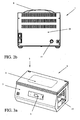
Figure 1 shows a front perspective view of a preferred embodiment of the improved packaging machine according to the present invention; -
Figures 2a and2b respectively show a front perspective view and a rear view of another embodiment of the improved packaging machine according to the present invention; -
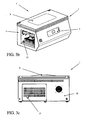
Figures 3a ,3b and 3c respectively show front perspective views and a rear view of another preferred embodiment of the improved packaging machine according to the present invention; -
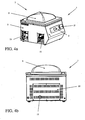
Figures 4a and 4b respectively show a front perspective view and a rear view of another preferred embodiment of the improved packaging machine according to the present invention; -
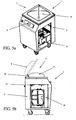
Figures 5a and 5b respectively show a top perspective view and a side view of another preferred embodiment of the improved packaging machine according to the present invention; -
Figures 6a and 6b respectively show two side views of another preferred embodiment of the improved packaging machine according to the present invention; and -
Figures 7a and 7b respectively show a top perspective view and a side view of another preferred embodiment of the improved packaging machine according to the present invention. - With reference then to the Figures, it is possible to note some preferred embodiments of the improved
packaging machine 1 according to the present invention. - The following description, for brevity, will not include all structural and operating details of the
packaging machine 1, that are known and belonging to the prior art. - With reference in particular to the Figures, it is possible to note that the improved
packaging machine 1 according to the present invention is composed of a supporting and containingstructure 3, obviously adapted to contain therein all functional members of themachine 1, that are substantially known in the art, and possibly to externally support at least one command andcontrol panel 5 of the operation of themachine 1, such supporting and containingstructure 3 comprising at least onedecompression chamber 7 for a vacuum packaging of a product, for example inside an envelope made of plastic material or another suitable vessel,such chamber 7 being composed of at least one tank covered by at least one basculatingbell 9 adapted for welding the open edges of such envelope, preferably through perimeter welding bars with which such bell is equipped. - Advantageously, the
packaging machine 1 according to the present invention is equipped with communication means connected to processing means and to printing means (suich as a printer or a label-printing machine). In particular, with reference for example toFigure 4a , it is possible to note that such communication means can be at least one communication port of the RS-232 type, through which it is possible to take, from the machine, operating packaging data, such as packaging date, expiry date of the packaged product, operator code, batch number, packaging data (percentages of vacuum, gas, pressure, welding time, etc.) in order to be afterwards processed by such processing means and such printing means. - In particular, advantageously, the external printing means, such as for example the label-printing machine, allow making, exactly at the time of packaging, the related adhesive labels to be directly and quickly applied to the newly packaged product, thereby practically integrating the labeling operation with the packaging operation, by means of the same and single operator. In order to make still more pratical the use of such external printing means, the
packaging machine 1 according to the present invention, and in particular next to the command andcontrol panel 5, can be equipped with at least onehousing seat 21 suitable for housing therein such printing means, and in particular the printer or the label-printing machine. Obviously, the communication means are arranged next tosuch housing seat 21. The application then of the printing of an adhesive label integrated with themachine 1 according to the present invention is a major item to guarantee the packaging: in fact, once that suitable means of themachine 1 have detected the above operating packaging data, all or part of such data are transmitted to the processing means and to the printing means through the communication means; in particular, such data can be transmitted to the label-printing machine, which includes them on a printout on an adhesive label that will be applied onto the envelope containing the product. In this way, the warranty of the vacuum packaged product is not limited to its package, but is also given by the traceability of the product itself. - Obviously, in addition to the above-described preferred embodiment, the communication means can be made according to any technology, also of the wireless type, known in the art and suitable for such purpose.
- Moreover, with particular reference to
Figures 1, 2a ,3b ,4a ,5b ,6b and7b , it is possible to note that the supporting and containingstructure 3 of thepackaging machine 1 according to the present invention can comprise at least one first access opening 11, possibly covered by at least one protecting panel (not shown) that can be easily removed, such first access opening 11 being suitably arranged next to theconnections 13 of the extendingdevices 14 for opening thebasculating bell 9 inside the supporting and containing structure 3: the first access opening 11 therefore allows a better access by an operator on the sides of themachine 1 for maintenance and, in particular, allows replacing the extendingdevices 14 themselves without the need of lifting the heat-shrinking tank, thereby making such operation easier and quicker. - In addition, the
packaging machine 1 according to the present invention can be equipped with at least one suitable power card as replacement of the traditional electro-mechanical box present in packaging machines belonging to the prior art: advantageously therefore, with particular reference toFigures 3a ,4a ,5a ,6a and7a , it is possible to note that the supporting and containingstructure 3 of thepackaging machine 1 according to the present invention can comprise at least one second access opening 15, also possibly covered by at least one protecting panel (not shown) that can be easily removed, such second access opening 15 being suitably arranged next to the power card arranged inside the supporting and containing structure 3: the second access opening 15 therefore allows a better access by an operator on the sides of themachine 1 for maintenance and, in particular, easily and quickly allows directly operating on the power card. - In addition, with particular reference to
Figures 2b ,3c and4b , it is possible to note that the supporting and containingstructure 3 of thepackaging machine 1 according to the present invention can comprise at least one window orhole 17 arranged next to a visor of the pump placed inside the supporting and containingstructure 3,such hole 17 being preferably arranged on arear wall 19 of such supporting and containingstructure 3 and being adapted to advantageously allow the immediate and practical check of the oil level of such pump without the need, by an operator, of accessing inside themachine 1. - In addition, the
packaging machine 1 according to the present invention can comprise at least one lamellar transformer as replacement of the traditional transformer used in known packaging machines: such lamellar transformer in fact advantageously confers more compactness to themachine 1 and guarantees a better operating regularity, being free from "spikes" upon activating themachine 1 according to the present invention. - In addition, the
packaging machine 1 according to the present invention can comprise protecting means, preferably made as at least one electronic card, against overheating of the welding bars of the basculating bell 9: in particular, such protecting means control the electric supply of the welding bars, avoiding that it becomes excessively prolonged, stopping it after a preset period of time (for example 4 seconds) in order to prevent a following overheating and sometimes the ignition of the bars with flames. - In addition, the
packaging machine 1 according to the present invention can comprise means for controlling and regulating the inlet speed of atmospheric air inside thedecompression chamber 7 at the end of the welding step, such means comprising at least one suitable inlet valve for such air controlled by means for managing the machine 1: advantageously, such means for controlling and regulating the inlet speed of atmospheric air allow optimally regulating the speed with which air re-enters inside thedecompression chamber 7, in order not to impair the stability of the envelopes in favour of the final aesthetic result of the package.
Claims (2)
- Improved packaging machine (1) composed of a supporting and containing structure (3) comprising at least one decompression chamber (7) for a vacuum packaging of a product, said chamber (7) being composed of at least one tank covered by at least one basculating bell (9) suitable for welding through perimeter welding bars with which said bell (9) is equipped, characterised in that it is equipped with communication means connected to processing means and to printing means, said communication means being adapted to transfer operating packaging data of said machine (1) to said processing means and to said printing means, said printing means being a printer or a label-printing machine adapted to print all or part of said operating packaging data, such as for example packaging date, expiry date of the packaged product, operator code, batch number, packaging data like percentage of vacuum, gas, pressure, welding time, on at least one adhesive label to be placed onto said product packaged with said machine (1).
- Packaging machine (1) according to claim 1, characterised in that it is equipped with at least one housing seat (21) adapted to house therein said printing means.
Priority Applications (1)
| Application Number | Priority Date | Filing Date | Title |
|---|---|---|---|
| PL10790675T PL2499050T3 (en) | 2009-11-11 | 2010-10-20 | Improved packaging machine |
Applications Claiming Priority (2)
| Application Number | Priority Date | Filing Date | Title |
|---|---|---|---|
| ITTO2009A000862A IT1398880B1 (en) | 2009-11-11 | 2009-11-11 | PERFECT PACKAGING MACHINE. |
| PCT/IT2010/000421 WO2011058589A1 (en) | 2009-11-11 | 2010-10-20 | Improved packaging machine |
Publications (2)
| Publication Number | Publication Date |
|---|---|
| EP2499050A1 EP2499050A1 (en) | 2012-09-19 |
| EP2499050B1 true EP2499050B1 (en) | 2013-07-24 |
Family
ID=42289795
Family Applications (1)
| Application Number | Title | Priority Date | Filing Date |
|---|---|---|---|
| EP10790675.2A Revoked EP2499050B1 (en) | 2009-11-11 | 2010-10-20 | Improved packaging machine |
Country Status (6)
| Country | Link |
|---|---|
| US (1) | US20120216486A1 (en) |
| EP (1) | EP2499050B1 (en) |
| ES (1) | ES2431830T3 (en) |
| IT (1) | IT1398880B1 (en) |
| PL (1) | PL2499050T3 (en) |
| WO (1) | WO2011058589A1 (en) |
Cited By (1)
| Publication number | Priority date | Publication date | Assignee | Title |
|---|---|---|---|---|
| CN109130147A (en) * | 2018-07-12 | 2019-01-04 | 东莞市松研智达工业设计有限公司 | Thermal-arrest shuttle coats complete machine |
Families Citing this family (3)
| Publication number | Priority date | Publication date | Assignee | Title |
|---|---|---|---|---|
| DE102012017827B4 (en) * | 2012-09-10 | 2021-07-15 | Multivac Sepp Haggenmüller Se & Co. Kg | Method for operating a chamber machine |
| JP7373333B2 (en) * | 2019-09-17 | 2023-11-02 | 株式会社Tosei | Vacuum packaging machine and vacuum packaging machine logging system |
| CN111703623A (en) * | 2020-06-24 | 2020-09-25 | 四川省绵阳市鸿永盛模塑有限公司 | Vacuum forming coating device and using method |
Family Cites Families (11)
| Publication number | Priority date | Publication date | Assignee | Title |
|---|---|---|---|---|
| US2367591A (en) * | 1942-10-02 | 1945-01-16 | Rca Corp | Split core transformer |
| GB1284509A (en) * | 1971-01-14 | 1972-08-09 | Grace W R & Co | Method and apparatus for vacuum welding of plastics envelopes |
| IT1024614B (en) * | 1976-03-03 | 1978-07-20 | Torre F | PACKAGING MACHINE FOR THE PACKAGING OF VARIOUS PRODUCTS IN A FILM OF SHRINKABLE MATERIAL |
| US4543766A (en) * | 1983-02-24 | 1985-10-01 | Hobart Corporation | Packaging system |
| IT1317130B1 (en) * | 2000-03-08 | 2003-05-27 | Italdibipack Spa | PACKAGING MACHINE FOR PRODUCTS WITH THERMO-Shrinkable FILM |
| WO2002010017A1 (en) * | 2000-08-02 | 2002-02-07 | Koch Equipment Llc | Injection-molded vacuum packaging machine |
| JP4165632B2 (en) * | 2000-12-12 | 2008-10-15 | 富士フイルム株式会社 | Method and apparatus for automatic packaging of case-filled products |
| ITMI20010270A1 (en) * | 2001-02-09 | 2002-08-09 | Germano Maina | MACHINE FOR VACUUM PACKAGING IN PLASTIC BAGS AND RIGID CONTAINERS |
| US7302784B2 (en) * | 2002-09-27 | 2007-12-04 | Depuy Products, Inc. | Vacuum packaging machine |
| US7204067B2 (en) * | 2003-02-27 | 2007-04-17 | Sunbeam Products, Inc. | Vacuum packaging appliance with removable trough |
| JP4220568B2 (en) * | 2007-04-02 | 2009-02-04 | 株式会社湯山製作所 | Drug packaging device |
-
2009
- 2009-11-11 IT ITTO2009A000862A patent/IT1398880B1/en active
-
2010
- 2010-10-20 WO PCT/IT2010/000421 patent/WO2011058589A1/en active Application Filing
- 2010-10-20 ES ES10790675T patent/ES2431830T3/en active Active
- 2010-10-20 PL PL10790675T patent/PL2499050T3/en unknown
- 2010-10-20 US US13/508,194 patent/US20120216486A1/en not_active Abandoned
- 2010-10-20 EP EP10790675.2A patent/EP2499050B1/en not_active Revoked
Cited By (1)
| Publication number | Priority date | Publication date | Assignee | Title |
|---|---|---|---|---|
| CN109130147A (en) * | 2018-07-12 | 2019-01-04 | 东莞市松研智达工业设计有限公司 | Thermal-arrest shuttle coats complete machine |
Also Published As
| Publication number | Publication date |
|---|---|
| EP2499050A1 (en) | 2012-09-19 |
| IT1398880B1 (en) | 2013-03-21 |
| WO2011058589A1 (en) | 2011-05-19 |
| ITTO20090862A1 (en) | 2010-02-10 |
| US20120216486A1 (en) | 2012-08-30 |
| ES2431830T3 (en) | 2013-11-28 |
| PL2499050T3 (en) | 2013-12-31 |
Similar Documents
| Publication | Publication Date | Title |
|---|---|---|
| EP2499050B1 (en) | Improved packaging machine | |
| HK1094437A1 (en) | Device and method for sterilization | |
| AR034719A1 (en) | METHOD AND SYSTEM FOR THE PLACEMENT AND / OR CONTROL OF A FOOD PRODUCT DISPENSING MACHINE, USING A LABEL TYPE COMMUNICATION DEVICE | |
| ITMI20100747A1 (en) | PACKAGING STRUCTURE FOR PHARMACEUTICAL CONTAINERS | |
| EP2411294B1 (en) | Carton with tamper evident prize information feature | |
| WO2006036995A3 (en) | Dynamic marking system | |
| CA2314411A1 (en) | Program control and display system for a cooking appliance | |
| ITRM20010639A0 (en) | MACHINE FOR PACKAGING ON SEVERAL ORDERED ROWS, IN BOXED CONTAINERS, OBJECTS FED IN ONE OR MORE ROWS. | |
| IT1316717B1 (en) | AUTOMATIC MACHINE FOR THE PACKAGING OF PRODUCTS WITHIN THE CONTAINERS | |
| WO2003043708A3 (en) | Item vending machine and method | |
| BRPI0722331B1 (en) | METHOD FOR MANUFACTURING A PLURALITY OF PLUG-IN CARDS FROM A CARD BODY | |
| WO2007000245A8 (en) | Direct integration of rfid elements into folding boxes | |
| CN104284845A (en) | Method for packing, packaging machine, computer program, and package | |
| CN101596944A (en) | A kind of skin packaging machine | |
| PL1979249T3 (en) | Method of packaging comestible products | |
| CA2429617A1 (en) | Method for applying an opening device to a packaging material and package obtained thereby | |
| EP2406171A1 (en) | Bag's fitting and a bag with said fitting | |
| EP2123564B1 (en) | Eelctronic control system of the packaging process with bell-type packaging machines | |
| JP4275520B2 (en) | Shrink package | |
| JP2022514682A (en) | Methods and systems for manufacturing packages | |
| JP4674941B2 (en) | How to include warranty card | |
| US20230271446A1 (en) | Enhanced late point feature differentiation | |
| KR101880945B1 (en) | A Unite Screen Printing and Sticker Attach System With Three Dimension Sticker Attach Function And A Container Decoration Method Thereof | |
| EP3085630A1 (en) | Printing cartridge for weighing-pricing scales and labelling machine | |
| US20100314365A1 (en) | Method and Apparatus for Using a Laser to Both Score and Emblazon a Wrapping Sheet |
Legal Events
| Date | Code | Title | Description |
|---|---|---|---|
| PUAI | Public reference made under article 153(3) epc to a published international application that has entered the european phase |
Free format text: ORIGINAL CODE: 0009012 |
|
| 17P | Request for examination filed |
Effective date: 20120525 |
|
| AK | Designated contracting states |
Kind code of ref document: A1 Designated state(s): AL AT BE BG CH CY CZ DE DK EE ES FI FR GB GR HR HU IE IS IT LI LT LU LV MC MK MT NL NO PL PT RO RS SE SI SK SM TR |
|
| DAX | Request for extension of the european patent (deleted) | ||
| GRAP | Despatch of communication of intention to grant a patent |
Free format text: ORIGINAL CODE: EPIDOSNIGR1 |
|
| RIC1 | Information provided on ipc code assigned before grant |
Ipc: B65B 31/02 20060101ALI20130222BHEP Ipc: B65B 61/26 20060101ALI20130222BHEP Ipc: B65B 51/10 20060101AFI20130222BHEP |
|
| RIN1 | Information on inventor provided before grant (corrected) |
Inventor name: TORRE, FRANCESCO Inventor name: TORRE, FABIO |
|
| GRAS | Grant fee paid |
Free format text: ORIGINAL CODE: EPIDOSNIGR3 |
|
| GRAA | (expected) grant |
Free format text: ORIGINAL CODE: 0009210 |
|
| AK | Designated contracting states |
Kind code of ref document: B1 Designated state(s): AL AT BE BG CH CY CZ DE DK EE ES FI FR GB GR HR HU IE IS IT LI LT LU LV MC MK MT NL NO PL PT RO RS SE SI SK SM TR |
|
| REG | Reference to a national code |
Ref country code: GB Ref legal event code: FG4D |
|
| REG | Reference to a national code |
Ref country code: CH Ref legal event code: EP |
|
| REG | Reference to a national code |
Ref country code: AT Ref legal event code: REF Ref document number: 623259 Country of ref document: AT Kind code of ref document: T Effective date: 20130815 |
|
| REG | Reference to a national code |
Ref country code: IE Ref legal event code: FG4D |
|
| REG | Reference to a national code |
Ref country code: DE Ref legal event code: R096 Ref document number: 602010008935 Country of ref document: DE Effective date: 20130919 |
|
| REG | Reference to a national code |
Ref country code: CH Ref legal event code: NV Representative=s name: MEYER AND KOLLEGEN, CH |
|
| REG | Reference to a national code |
Ref country code: NL Ref legal event code: T3 |
|
| REG | Reference to a national code |
Ref country code: LT Ref legal event code: MG4D |
|
| REG | Reference to a national code |
Ref country code: PL Ref legal event code: T3 |
|
| PG25 | Lapsed in a contracting state [announced via postgrant information from national office to epo] |
Ref country code: CY Free format text: LAPSE BECAUSE OF FAILURE TO SUBMIT A TRANSLATION OF THE DESCRIPTION OR TO PAY THE FEE WITHIN THE PRESCRIBED TIME-LIMIT Effective date: 20130911 Ref country code: SE Free format text: LAPSE BECAUSE OF FAILURE TO SUBMIT A TRANSLATION OF THE DESCRIPTION OR TO PAY THE FEE WITHIN THE PRESCRIBED TIME-LIMIT Effective date: 20130724 Ref country code: PT Free format text: LAPSE BECAUSE OF FAILURE TO SUBMIT A TRANSLATION OF THE DESCRIPTION OR TO PAY THE FEE WITHIN THE PRESCRIBED TIME-LIMIT Effective date: 20131125 Ref country code: NO Free format text: LAPSE BECAUSE OF FAILURE TO SUBMIT A TRANSLATION OF THE DESCRIPTION OR TO PAY THE FEE WITHIN THE PRESCRIBED TIME-LIMIT Effective date: 20131024 Ref country code: LT Free format text: LAPSE BECAUSE OF FAILURE TO SUBMIT A TRANSLATION OF THE DESCRIPTION OR TO PAY THE FEE WITHIN THE PRESCRIBED TIME-LIMIT Effective date: 20130724 Ref country code: IS Free format text: LAPSE BECAUSE OF FAILURE TO SUBMIT A TRANSLATION OF THE DESCRIPTION OR TO PAY THE FEE WITHIN THE PRESCRIBED TIME-LIMIT Effective date: 20131124 Ref country code: HR Free format text: LAPSE BECAUSE OF FAILURE TO SUBMIT A TRANSLATION OF THE DESCRIPTION OR TO PAY THE FEE WITHIN THE PRESCRIBED TIME-LIMIT Effective date: 20130724 |
|
| PG25 | Lapsed in a contracting state [announced via postgrant information from national office to epo] |
Ref country code: SI Free format text: LAPSE BECAUSE OF FAILURE TO SUBMIT A TRANSLATION OF THE DESCRIPTION OR TO PAY THE FEE WITHIN THE PRESCRIBED TIME-LIMIT Effective date: 20130724 Ref country code: FI Free format text: LAPSE BECAUSE OF FAILURE TO SUBMIT A TRANSLATION OF THE DESCRIPTION OR TO PAY THE FEE WITHIN THE PRESCRIBED TIME-LIMIT Effective date: 20130724 Ref country code: GR Free format text: LAPSE BECAUSE OF FAILURE TO SUBMIT A TRANSLATION OF THE DESCRIPTION OR TO PAY THE FEE WITHIN THE PRESCRIBED TIME-LIMIT Effective date: 20131025 Ref country code: LV Free format text: LAPSE BECAUSE OF FAILURE TO SUBMIT A TRANSLATION OF THE DESCRIPTION OR TO PAY THE FEE WITHIN THE PRESCRIBED TIME-LIMIT Effective date: 20130724 |
|
| PG25 | Lapsed in a contracting state [announced via postgrant information from national office to epo] |
Ref country code: CY Free format text: LAPSE BECAUSE OF FAILURE TO SUBMIT A TRANSLATION OF THE DESCRIPTION OR TO PAY THE FEE WITHIN THE PRESCRIBED TIME-LIMIT Effective date: 20130724 |
|
| PG25 | Lapsed in a contracting state [announced via postgrant information from national office to epo] |
Ref country code: SK Free format text: LAPSE BECAUSE OF FAILURE TO SUBMIT A TRANSLATION OF THE DESCRIPTION OR TO PAY THE FEE WITHIN THE PRESCRIBED TIME-LIMIT Effective date: 20130724 Ref country code: EE Free format text: LAPSE BECAUSE OF FAILURE TO SUBMIT A TRANSLATION OF THE DESCRIPTION OR TO PAY THE FEE WITHIN THE PRESCRIBED TIME-LIMIT Effective date: 20130724 Ref country code: DK Free format text: LAPSE BECAUSE OF FAILURE TO SUBMIT A TRANSLATION OF THE DESCRIPTION OR TO PAY THE FEE WITHIN THE PRESCRIBED TIME-LIMIT Effective date: 20130724 Ref country code: RO Free format text: LAPSE BECAUSE OF FAILURE TO SUBMIT A TRANSLATION OF THE DESCRIPTION OR TO PAY THE FEE WITHIN THE PRESCRIBED TIME-LIMIT Effective date: 20130724 |
|
| PLBI | Opposition filed |
Free format text: ORIGINAL CODE: 0009260 |
|
| PG25 | Lapsed in a contracting state [announced via postgrant information from national office to epo] |
Ref country code: MC Free format text: LAPSE BECAUSE OF FAILURE TO SUBMIT A TRANSLATION OF THE DESCRIPTION OR TO PAY THE FEE WITHIN THE PRESCRIBED TIME-LIMIT Effective date: 20130724 |
|
| PLAX | Notice of opposition and request to file observation + time limit sent |
Free format text: ORIGINAL CODE: EPIDOSNOBS2 |
|
| 26 | Opposition filed |
Opponent name: MULTIVAC SEPP HAGGENMUELLER GMBH & CO. KG Effective date: 20140423 |
|
| REG | Reference to a national code |
Ref country code: DE Ref legal event code: R026 Ref document number: 602010008935 Country of ref document: DE Effective date: 20140423 |
|
| PLBB | Reply of patent proprietor to notice(s) of opposition received |
Free format text: ORIGINAL CODE: EPIDOSNOBS3 |
|
| PG25 | Lapsed in a contracting state [announced via postgrant information from national office to epo] |
Ref country code: SM Free format text: LAPSE BECAUSE OF FAILURE TO SUBMIT A TRANSLATION OF THE DESCRIPTION OR TO PAY THE FEE WITHIN THE PRESCRIBED TIME-LIMIT Effective date: 20130724 |
|
| PG25 | Lapsed in a contracting state [announced via postgrant information from national office to epo] |
Ref country code: LU Free format text: LAPSE BECAUSE OF NON-PAYMENT OF DUE FEES Effective date: 20131020 Ref country code: HU Free format text: LAPSE BECAUSE OF FAILURE TO SUBMIT A TRANSLATION OF THE DESCRIPTION OR TO PAY THE FEE WITHIN THE PRESCRIBED TIME-LIMIT; INVALID AB INITIO Effective date: 20101020 Ref country code: MK Free format text: LAPSE BECAUSE OF FAILURE TO SUBMIT A TRANSLATION OF THE DESCRIPTION OR TO PAY THE FEE WITHIN THE PRESCRIBED TIME-LIMIT Effective date: 20130724 Ref country code: RS Free format text: LAPSE BECAUSE OF FAILURE TO SUBMIT A TRANSLATION OF THE DESCRIPTION OR TO PAY THE FEE WITHIN THE PRESCRIBED TIME-LIMIT Effective date: 20131024 Ref country code: BG Free format text: LAPSE BECAUSE OF FAILURE TO SUBMIT A TRANSLATION OF THE DESCRIPTION OR TO PAY THE FEE WITHIN THE PRESCRIBED TIME-LIMIT Effective date: 20130724 |
|
| PG25 | Lapsed in a contracting state [announced via postgrant information from national office to epo] |
Ref country code: MT Free format text: LAPSE BECAUSE OF FAILURE TO SUBMIT A TRANSLATION OF THE DESCRIPTION OR TO PAY THE FEE WITHIN THE PRESCRIBED TIME-LIMIT Effective date: 20130724 |
|
| REG | Reference to a national code |
Ref country code: FR Ref legal event code: PLFP Year of fee payment: 6 |
|
| PLAB | Opposition data, opponent's data or that of the opponent's representative modified |
Free format text: ORIGINAL CODE: 0009299OPPO |
|
| R26 | Opposition filed (corrected) |
Opponent name: MULTIVAC SEPP HAGGENMUELLER SE & CO. KG Effective date: 20140423 |
|
| REG | Reference to a national code |
Ref country code: FR Ref legal event code: PLFP Year of fee payment: 7 |
|
| RDAF | Communication despatched that patent is revoked |
Free format text: ORIGINAL CODE: EPIDOSNREV1 |
|
| STAA | Information on the status of an ep patent application or granted ep patent |
Free format text: STATUS: THE PATENT HAS BEEN GRANTED |
|
| APBM | Appeal reference recorded |
Free format text: ORIGINAL CODE: EPIDOSNREFNO |
|
| APBP | Date of receipt of notice of appeal recorded |
Free format text: ORIGINAL CODE: EPIDOSNNOA2O |
|
| APAH | Appeal reference modified |
Free format text: ORIGINAL CODE: EPIDOSCREFNO |
|
| APBQ | Date of receipt of statement of grounds of appeal recorded |
Free format text: ORIGINAL CODE: EPIDOSNNOA3O |
|
| REG | Reference to a national code |
Ref country code: FR Ref legal event code: PLFP Year of fee payment: 8 |
|
| PGFP | Annual fee paid to national office [announced via postgrant information from national office to epo] |
Ref country code: CZ Payment date: 20171019 Year of fee payment: 8 Ref country code: DE Payment date: 20171027 Year of fee payment: 8 Ref country code: TR Payment date: 20171018 Year of fee payment: 8 Ref country code: FR Payment date: 20171025 Year of fee payment: 8 |
|
| PGFP | Annual fee paid to national office [announced via postgrant information from national office to epo] |
Ref country code: CH Payment date: 20171027 Year of fee payment: 8 Ref country code: IE Payment date: 20171031 Year of fee payment: 8 Ref country code: GB Payment date: 20171027 Year of fee payment: 8 Ref country code: NL Payment date: 20171026 Year of fee payment: 8 Ref country code: ES Payment date: 20171102 Year of fee payment: 8 Ref country code: PL Payment date: 20171020 Year of fee payment: 8 Ref country code: IT Payment date: 20171027 Year of fee payment: 8 Ref country code: BE Payment date: 20171027 Year of fee payment: 8 Ref country code: AT Payment date: 20171019 Year of fee payment: 8 |
|
| PG25 | Lapsed in a contracting state [announced via postgrant information from national office to epo] |
Ref country code: AL Free format text: LAPSE BECAUSE OF FAILURE TO SUBMIT A TRANSLATION OF THE DESCRIPTION OR TO PAY THE FEE WITHIN THE PRESCRIBED TIME-LIMIT Effective date: 20130724 |
|
| REG | Reference to a national code |
Ref country code: DE Ref legal event code: R119 Ref document number: 602010008935 Country of ref document: DE |
|
| REG | Reference to a national code |
Ref country code: CH Ref legal event code: PL |
|
| REG | Reference to a national code |
Ref country code: NL Ref legal event code: MM Effective date: 20181101 |
|
| REG | Reference to a national code |
Ref country code: AT Ref legal event code: MM01 Ref document number: 623259 Country of ref document: AT Kind code of ref document: T Effective date: 20181020 |
|
| GBPC | Gb: european patent ceased through non-payment of renewal fee |
Effective date: 20181020 |
|
| REG | Reference to a national code |
Ref country code: BE Ref legal event code: MM Effective date: 20181031 |
|
| REG | Reference to a national code |
Ref country code: IE Ref legal event code: MM4A |
|
| PG25 | Lapsed in a contracting state [announced via postgrant information from national office to epo] |
Ref country code: NL Free format text: LAPSE BECAUSE OF NON-PAYMENT OF DUE FEES Effective date: 20181101 Ref country code: DE Free format text: LAPSE BECAUSE OF NON-PAYMENT OF DUE FEES Effective date: 20190501 Ref country code: CZ Free format text: LAPSE BECAUSE OF NON-PAYMENT OF DUE FEES Effective date: 20181020 |
|
| PG25 | Lapsed in a contracting state [announced via postgrant information from national office to epo] |
Ref country code: LI Free format text: LAPSE BECAUSE OF NON-PAYMENT OF DUE FEES Effective date: 20181031 Ref country code: BE Free format text: LAPSE BECAUSE OF NON-PAYMENT OF DUE FEES Effective date: 20181031 Ref country code: FR Free format text: LAPSE BECAUSE OF NON-PAYMENT OF DUE FEES Effective date: 20181031 Ref country code: CH Free format text: LAPSE BECAUSE OF NON-PAYMENT OF DUE FEES Effective date: 20181031 |
|
| PG25 | Lapsed in a contracting state [announced via postgrant information from national office to epo] |
Ref country code: GB Free format text: LAPSE BECAUSE OF NON-PAYMENT OF DUE FEES Effective date: 20181020 Ref country code: AT Free format text: LAPSE BECAUSE OF NON-PAYMENT OF DUE FEES Effective date: 20181020 Ref country code: IE Free format text: LAPSE BECAUSE OF NON-PAYMENT OF DUE FEES Effective date: 20181020 Ref country code: IT Free format text: LAPSE BECAUSE OF NON-PAYMENT OF DUE FEES Effective date: 20181020 |
|
| REG | Reference to a national code |
Ref country code: ES Ref legal event code: FD2A Effective date: 20191203 |
|
| PG25 | Lapsed in a contracting state [announced via postgrant information from national office to epo] |
Ref country code: ES Free format text: LAPSE BECAUSE OF NON-PAYMENT OF DUE FEES Effective date: 20181021 |
|
| PG25 | Lapsed in a contracting state [announced via postgrant information from national office to epo] |
Ref country code: PL Free format text: LAPSE BECAUSE OF NON-PAYMENT OF DUE FEES Effective date: 20181020 |
|
| APBU | Appeal procedure closed |
Free format text: ORIGINAL CODE: EPIDOSNNOA9O |
|
| REG | Reference to a national code |
Ref country code: DE Ref legal event code: R064 Ref document number: 602010008935 Country of ref document: DE Ref country code: DE Ref legal event code: R103 Ref document number: 602010008935 Country of ref document: DE |
|
| RDAG | Patent revoked |
Free format text: ORIGINAL CODE: 0009271 |
|
| STAA | Information on the status of an ep patent application or granted ep patent |
Free format text: STATUS: PATENT REVOKED |
|
| REG | Reference to a national code |
Ref country code: FI Ref legal event code: MGE |
|
| 27W | Patent revoked |
Effective date: 20200519 |
|
| REG | Reference to a national code |
Ref country code: AT Ref legal event code: MA03 Ref document number: 623259 Country of ref document: AT Kind code of ref document: T Effective date: 20200519 |
|
| PG25 | Lapsed in a contracting state [announced via postgrant information from national office to epo] |
Ref country code: TR Free format text: LAPSE BECAUSE OF NON-PAYMENT OF DUE FEES Effective date: 20181020 |