EP2498065A2 - Baueinheit einer Winkelmesseinrichtung und Verfahren zur Herstellung dieser Baueinheit - Google Patents
Baueinheit einer Winkelmesseinrichtung und Verfahren zur Herstellung dieser Baueinheit Download PDFInfo
- Publication number
- EP2498065A2 EP2498065A2 EP11194721A EP11194721A EP2498065A2 EP 2498065 A2 EP2498065 A2 EP 2498065A2 EP 11194721 A EP11194721 A EP 11194721A EP 11194721 A EP11194721 A EP 11194721A EP 2498065 A2 EP2498065 A2 EP 2498065A2
- Authority
- EP
- European Patent Office
- Prior art keywords
- graduation carrier
- adhesive
- holder
- positioning element
- graduation
- Prior art date
- Legal status (The legal status is an assumption and is not a legal conclusion. Google has not performed a legal analysis and makes no representation as to the accuracy of the status listed.)
- Granted
Links
Images


Classifications
-
- G—PHYSICS
- G01—MEASURING; TESTING
- G01D—MEASURING NOT SPECIALLY ADAPTED FOR A SPECIFIC VARIABLE; ARRANGEMENTS FOR MEASURING TWO OR MORE VARIABLES NOT COVERED IN A SINGLE OTHER SUBCLASS; TARIFF METERING APPARATUS; MEASURING OR TESTING NOT OTHERWISE PROVIDED FOR
- G01D5/00—Mechanical means for transferring the output of a sensing member; Means for converting the output of a sensing member to another variable where the form or nature of the sensing member does not constrain the means for converting; Transducers not specially adapted for a specific variable
- G01D5/26—Mechanical means for transferring the output of a sensing member; Means for converting the output of a sensing member to another variable where the form or nature of the sensing member does not constrain the means for converting; Transducers not specially adapted for a specific variable characterised by optical transfer means, i.e. using infrared, visible, or ultraviolet light
- G01D5/32—Mechanical means for transferring the output of a sensing member; Means for converting the output of a sensing member to another variable where the form or nature of the sensing member does not constrain the means for converting; Transducers not specially adapted for a specific variable characterised by optical transfer means, i.e. using infrared, visible, or ultraviolet light with attenuation or whole or partial obturation of beams of light
- G01D5/34—Mechanical means for transferring the output of a sensing member; Means for converting the output of a sensing member to another variable where the form or nature of the sensing member does not constrain the means for converting; Transducers not specially adapted for a specific variable characterised by optical transfer means, i.e. using infrared, visible, or ultraviolet light with attenuation or whole or partial obturation of beams of light the beams of light being detected by photocells
- G01D5/347—Mechanical means for transferring the output of a sensing member; Means for converting the output of a sensing member to another variable where the form or nature of the sensing member does not constrain the means for converting; Transducers not specially adapted for a specific variable characterised by optical transfer means, i.e. using infrared, visible, or ultraviolet light with attenuation or whole or partial obturation of beams of light the beams of light being detected by photocells using displacement encoding scales
- G01D5/34707—Scales; Discs, e.g. fixation, fabrication, compensation
-
- Y—GENERAL TAGGING OF NEW TECHNOLOGICAL DEVELOPMENTS; GENERAL TAGGING OF CROSS-SECTIONAL TECHNOLOGIES SPANNING OVER SEVERAL SECTIONS OF THE IPC; TECHNICAL SUBJECTS COVERED BY FORMER USPC CROSS-REFERENCE ART COLLECTIONS [XRACs] AND DIGESTS
- Y10—TECHNICAL SUBJECTS COVERED BY FORMER USPC
- Y10T—TECHNICAL SUBJECTS COVERED BY FORMER US CLASSIFICATION
- Y10T156/00—Adhesive bonding and miscellaneous chemical manufacture
- Y10T156/10—Methods of surface bonding and/or assembly therefor
Definitions
- the present invention relates to an assembly of an angle measuring device according to the preamble of claim 1.
- Such a unit is in the EP 0 386 268 B1 described. It has already been found to be advantageous to attach a graduation carrier by gluing on the underside of the graduation carrier to a holder, so that no central hole in the graduation carrier is required.
- the disadvantage here is that the positioning between the graduation carrier and the holder is difficult to achieve.
- a holder acts in most cases a drive shaft of a drive unit, so that the attachment of the graduation carrier does not take place at the manufacturer of the graduation carrier or the angle measuring device, but only at the manufacturer of the drive unit.
- Object of the present invention is therefore to provide a structural unit for an angle measuring device, which allows a simple and stable mounting of a graduation carrier.
- this assembly for an angle measuring device comprises a positioning element which is fastened by means of a material connection, in particular an adhesive bond, to a graduation carrier.
- the positioning carrier carrying the graduation carrier is arranged in a recess of a holder, wherein the cutout positions the positioning element in the radial direction by forming a play-free fit for the positioning element in the radial direction.
- a cohesive connection in particular an adhesive connection, provided between the graduation carrier and the holder.
- the positioning element With a plane perpendicular to the axis of rotation plane surface of the graduation carrier materially connected, in particular glued, a parallel orientation of the positioning is ensured to the axis of rotation.
- the cohesive connection, in particular adhesive bond, between the graduation carrier and the holder takes place in a region which is further away from the axis of rotation in the radial direction than the region on which the cohesive connection, in particular adhesion, takes place between the graduation carrier and the positioning element.
- a relatively large-area cohesive connection, in particular adhesion, between the graduation carrier and the holder is ensured.
- Mass moment of inertia of the unit nevertheless a simple and stable connection between the graduation carrier and the holder is achieved.
- the assembly is thus particularly suitable for measuring rotational movements about the axis of rotation at which high spins occur.
- the assembly is therefore particularly suitable for highly accurate position measurement of parts that perform motion with a rapidly changing direction of motion, such as vibrating mirrors, pick and place tools or bonding tools.
- a further object of the invention is to provide a method for producing an assembly for an angle measuring device, which allows a simple, precise and stable assembly.
- a cohesive connection in particular adhesive bond
- the positioning carrier carrying the graduation carrier is inserted into a recess of the holder, wherein the recess positions the positioning element in the radial direction without play.
- a further cohesive connection in particular adhesive connection, is produced between the graduation carrier and the holder.
- Cohesive connection means joining by gluing, cementing, soldering or welding.
- Bonding means joining the parts to be joined with an adhesive.
- An adhesive bond consists of the two parts to be joined and the one in between lying adhesive layer.
- the adhesive can be cured by physical processes such as light or heat or by chemical reactions. Bonding has the special advantage that the parts to be joined can consist of different materials and that no or only minimal heat input takes place.
- the bonding method is therefore preferred according to the invention, since the graduation carrier can then be made of glass or glass ceramic and the holder made of metal.
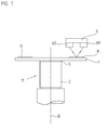
- FIG. 1 is an angle measuring device with an inventively designed unit 10 is shown.
- the assembly 10 has a holder 2 in the form of a shaft rotatable about a rotation axis D.
- the end of the holder 2 has a fastening surface extending perpendicular to the axis of rotation D for adhesive attachment of a graduation carrier 1.
- the graduation carrier 1 has a graduation 11, which is designed to be scanned by photoelectrification.
- the assembly 10 is supplemented by a scanning device 6.
- This scanning device 6 has a light source 61, which emits a light beam which strikes the division 11 and is modulated position-dependent there upon rotation of the assembly 10 relative to the scanning device 6. This position-dependent modulated light is reflected and impinges on a light receiver 62 of the scanning device 6.
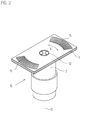
- the graduation carrier 1 is rectangular in this example.
- the division 11 is not carried out over the entire circumference, since a position measurement takes place only over a fraction of 360 °, for example over 15 °.
- the rectangular graduation carrier 1 it is also possible to use a circular graduation carrier which has a graduation over a full 360 ° in order to enable a position measurement over a full revolution.
- the graduation carrier 1 is disc-shaped or plate-shaped with two flat and mutually parallel surfaces. It preferably consists of a transparent material, in particular glass or glass ceramic.
- the division 11 is applied to one of the two mutually parallel surfaces of the graduation carrier 1 as a reflective photoelectrically scannable structure, this may be an amplitude structure or a phase structure.
- the division 11 is a radial pitch whose center lies in the axis of rotation D. Instead of the reflective graduation 11, it is also possible to provide a graduation which can be scanned in the transmitted light on the graduation carrier 1.
- the division 11 may be an incremental division for the relative measurement of a position or a code for the absolute position measurement.
- a preferably pin-shaped positioning element 3 in the center of the radial pitch 11 - ie in the axis of rotation D - is glued to the graduation carrier 1.
- This adhesive bond takes place between a perpendicular to the axis of rotation D extending surface 13 of the graduation carrier 1 and a parallel thereto front end of the positioning element 3 by means of an adhesive 4.
- This adhesive 4 is a thin-surface axial layer between the front end of the positioning element 3 and perpendicular to the axis of rotation D extending surface 13 of the graduation carrier 1 is provided.
- there is a surface bond in which no mounting hole in the graduation carrier 1 is required.
- the planar connection between an end face of the holder 2 and the underside 13 of the graduation carrier 1 extending parallel thereto ensures a parallel alignment of the positioning element 3 with the axis of rotation D of the graduation carrier 1.
- the adhesive 4 can be applied to the front side of the positioning element 3 or the underside 13 of the graduation carrier 1 before the joining of the graduation carrier 1 and the positioning element 3 or it is laterally introduced to the already crowded parts 1 and 3.
- the positioning element 3 can also have a bore extending parallel to the axis of rotation D, so that the adhesive can be introduced from the back into the bore in the direction of the surface 13 of the graduation carrier 1.
- a marking 12 of the graduation carrier 1 which is designed as a crosshair and / or as a ring mark.
- This marking 12 has preferably been applied in a common method step with the division 11 on the graduation carrier 1 and thus has a fixed predetermined assignment to the division 11th
- the connection of the graduation carrier 1 takes place with the holder 2.
- a parallel to the axis of rotation D extending, in particular centrally disposed recess 21 is provided in the holder 2, in which the, the graduation carrier 1 supporting positioning element 3, is used.
- the recess 21 is dimensioned in the radial direction (perpendicular to the axis of rotation D) such that it forms a play-free fit for the positioning element 3.
- the depth of the recess in the direction of the axis of rotation D is chosen such that after the insertion of the positioning element 3 into the recess 21 an adhesive bond between the holder 2 and the graduation carrier 1 is made possible, between a perpendicular to the axis of rotation D extending end face of the holder. 2 and the surface 13 of the graduation carrier 1 running parallel to this end face FIG. 3
- an adhesive 5 is introduced between the annular end face of the holder 2 and the underside 13 of the graduation carrier 1, so that an adhesive layer which is thin in the axial direction is formed.
- FIG. 4 the assembled assembly 10 is shown in section.
- the manufacturer of the graduation carrier 1 can preconfigure this with the positioning element 3.
- This preconfigured component can then be connected by the manufacturer of a drive unit without complex assembly work with a drive shaft.
- the positioning element 3, in conjunction with the precisely fitting recess 21, ensures an exact radial association between the graduation carrier 1 and the holder 2 and thus also between the graduation 11 and the axis of rotation D.
- the adhesive bond with the adhesive 5 ensures a stable frictional connection between the graduation carrier 1 and the Holder 2, which is preferably the said drive shaft of a drive unit.
- the adhesive 5 is preferably a radiation-curable adhesive, in particular an adhesive which cures by irradiation with UV light. This makes it possible to cure the adhesive 5 through the graduation carrier 1 by means of UV light.
- the graduation carrier 1 is made of a material which is transparent to UV light, in particular of glass or glass ceramic.
- the adhesive 4 is preferably a radiation-curable adhesive which is irradiated through the graduation support 1 with UV light and thereby cured.
- adhesives 4, 5 curable by means of radiation in particular UV radiation, has the advantage of targeted and rapid curing.
- the positioning element 3 has a groove 31.
- this groove 31 can be used for targeted introduction of the adhesive 4 between the positioning element 3 and the graduation carrier 1 and, on the other hand, as a pocket for receiving excess adhesive 4 or adhesive 5.
- only one chamfer on the positioning element can be used for this purpose. or be provided on the holder 2.
- a recess such as in the mentioned EP 0 386 268 B1 proposed.
- a recess for receiving adhesive 5 may be provided at the front end of the holder 2.
- the division 11 is photoelectrically scanned in the example shown, since this scanning ensures a highly accurate position measurement.
- the invention is not limited thereto, for example, the division can also be designed to be scanned magnetically, capacitively or inductively.
Landscapes
- Physics & Mathematics (AREA)
- General Physics & Mathematics (AREA)
- Optical Transform (AREA)
- Transmission And Conversion Of Sensor Element Output (AREA)
Abstract
Description
- Die vorliegende Erfindung betrifft eine Baueinheit einer Winkelmesseinrichtung gemäß dem Oberbegriff des Anspruchs 1.
- Eine derartige Baueinheit ist in der
EP 0 386 268 B1 beschrieben. Dabei wurde bereits als vorteilhaft erkannt, einen Teilungsträger durch Kleben an der Unterseite des Teilungsträgers an einem Halter zu befestigen, so dass kein zentrales Loch in dem Teilungsträger erforderlich ist. - Nachteilig dabei ist, dass die Positionierung zwischen dem Teilungsträger und dem Halter schwierig realisierbar ist. Als Halter fungiert in den meisten Fällen eine Antriebswelle einer Antriebseinheit, so dass die Befestigung des Teilungsträgers nicht beim Hersteller des Teilungsträgers bzw. der Winkelmesseinrichtung erfolgt, sondern erst beim Hersteller der Antriebseinheit.
- Aufgabe der vorliegenden Erfindung ist es daher, eine Baueinheit für eine Winkelmesseinrichtung anzugeben, die eine einfache und stabile Montage eines Teilungsträgers ermöglicht.
- Diese Aufgabe wird erfindungsgemäß durch eine Baueinheit mit den Merkmalen des Anspruchs 1 gelöst.
- Demnach umfasst diese Baueinheit für eine Winkelmesseinrichtung ein Positionierelement, das mittels einer stoffschlüssigen Verbindung, insbesonder einer Klebeverbindung, an einem Teilungsträger befestigt ist. Das den Teilungsträger tragende Positionierelement ist in einer Ausnehmung eines Halters angeordnet, wobei die Ausnehmung das Positionierelement in radialer Richtung positioniert, indem diese für das Positionierelement in radialer Richtung eine spielfreie Passung bildet. Zur stabilen Befestigung des Teilungsträgers am Halter ist zwischen dem Teilungsträger und dem Halter ebenfalls eine stoffschlüssige Verbindung, insbesondere eine Klebeverbindung, vorgesehen.
- Indem das Positionierelement mit einer senkrecht zur Drehachse verlaufenden Planfläche des Teilungsträgers stoffschlüssig verbunden, insbesondere verklebt wird, ist eine parallele Ausrichtung des Positionierelementes zur Drehachse gewährleistet. Die stoffschlüssige Verbindung, insbesondere Klebeverbindung, zwischen dem Teilungsträger und dem Halter erfolgt in einem Bereich, der von der Drehachse in radialer Richtung weiter entfernt ist als der Bereich, an dem die stoffschlüssige Verbindung, insbesondere Klebung, zwischen dem Teilungsträger und dem Positionierelement erfolgt. Dadurch ist eine relativ großflächige stoffschlüssige Verbindung, insbesondere Klebung, zwischen dem Teilungsträger und dem Halter gewährleistet. Diese großflächige und von der Drehachse radial entfernte stoffschlüssige Verbindung, insbesondere Klebung, zwischen dem Teilungsträger und dem Halter führt zu einer stabilen Befestigung, die auch bei hohen Beschleunigungen eine exakte Winkelübertragung von dem Halter -der vorzugsweise eine Antriebswelle einer Antriebseinrichtung ist- auf den Teilungsträger gewährleistet.
- Durch die erfindungsgemäße Ausgestaltung ist die Massenverteilung der Baueinheit optimiert, so dass bei Einhaltung eines geringen
- Massenträgheitsmoments der Baueinheit trotzdem eine einfache und stabile Verbindung zwischen dem Teilungsträger und dem Halter erreicht wird.
- Die Baueinheit ist somit insbesondere zur Messung von Drehbewegungen um die Drehachse geeignet, bei denen hohe Drehbeschleunigungen auftreten. Die Baueinheit eignet sich daher besonders zur hochgenauen Positionsmessung von Teilen, die eine Bewegung mit sich schnell ändernder Bewegungsrichtung ausführen, wie Schwingspiegel, pick and place Werkzeuge oder Bondwerkzeuge.
- Eine Winkelmesseinrichtung mit der erfindungsgemäß ausgebildeten Baueinheit ist im Anspruch 8 angegeben.
- Eine weitere Aufgabe der Erfindung besteht darin, ein Verfahren zur Herstellung einer Baueinheit für eine Winkelmesseinrichtung anzugeben, die eine einfache, präzise und stabile Montage erlaubt.
- Diese Aufgabe wird erfindungsgemäß durch ein Verfahren mit den Merkmalen des Anspruchs 9 gelöst.
- Demnach wird eine stoffschlüssige Verbindung, insbesondere Klebeverbindung, zwischen einem Teilungsträger und einem Positionierelement hergestellt. Das den Teilungsträger tragende Positionierelement wird in eine Ausnehmung des Halters eingesetzt, wobei die Ausnehmung das Positionierelement in radialer Richtung spielfrei positioniert. In dieser radial positionierten Stellung wird eine weitere stoffschlüssige Verbindung, insbesondere Klebeverbindung, zwischen dem Teilungsträger und dem Halter hergestellt.
- Stoffschlüssige Verbindung bedeutet Fügen durch Kleben, Kitten, Löten oder Schweißen.
- Kleben bedeutet Fügen der Fügeteile mittels eines Klebstoffes. Eine Klebeverbindung besteht aus den beiden Fügeteilen und der dazwischen liegenden Kleberschicht. Der Klebstoff kann durch physikalische Vorgänge wie Licht oder Wärme oder durch chemische Reaktionen ausgehärtet werden. Kleben hat den besonderen Vorteil, dass die zu fügenden Teile aus unterschiedlichen Materialien bestehen können und dass keine oder nur geringster Wärmeeintrag erfolgt. Das Klebeverfahren wird daher gemäß der Erfindung bevorzugt, da der Teilungsträger dann aus Glas oder Glaskeramik und der Halter aus Metall ausgeführt sein können.
- Vorteile sowie Einzelheiten der vorliegenden Erfindung ergeben sich aus der nachfolgenden Beschreibung eines Ausführungsbeispiels anhand der beiliegenden Figuren.
- Es zeigen
- Figur 1
- eine Winkelmesseinrichtung mit einer erfindungsgemäß ausgestalteten Baueinheit;
- Figur 2
- die Baueinheit der Winkelmesseinrichtung in perspektivischer Ansicht;
- Figur 3
- die Komponenten der Baueinheit im Schnitt und während des Zusammenbaus, und
- Figur 4
- die komplettierte Baueinheit gemäß der
Figuren 2 und3 im Schnitt. - In
Figur 1 ist eine Winkelmesseinrichtung mit einer erfindungsgemäß ausgestalteten Baueinheit 10 dargestellt. Die Baueinheit 10 weist einen Halter 2 in Form einer um eine Drehachse D drehbaren Welle auf. Das Ende des Halters 2 weist eine zur Drehachse D senkrecht verlaufende Befestigungsfläche zur klebenden Befestigung eines Teilungsträgers 1 auf. Die Klebeverbindung zwischen diesem Ende des Halters 2 und der Unterseite 13 des Teilungsträgers 1 erfolgt mittels eines Klebstoffs 5. - Der Teilungsträger 1 weist eine Teilung 11 auf, die lichtelektrisch abtastbar ausgestaltet ist. Zur Messung eines Drehwinkels X um die Drehachse D ist die Baueinheit 10 um eine Abtasteinrichtung 6 ergänzt. Diese Abtasteinrichtung 6 weist eine Lichtquelle 61 auf, die ein Lichtbündel aussendet, das auf die Teilung 11 trifft und dort bei einer Drehung der Baueinheit 10 relativ zur Abtasteinrichtung 6 positionsabhängig moduliert wird. Dieses positionsabhängig modulierte Licht wird reflektiert und trifft auf einen Lichtempfänger 62 der Abtasteinrichtung 6.
- Anhand der
Figuren 2 bis 4 wird nachfolgend die Baueinheit 10 der Winkelmesseinrichtung noch näher beschrieben. - Wie in
Figur 2 erkennbar ist, ist der Teilungsträger 1 in diesem Beispiel rechteckförmig ausgeführt. Die Teilung 11 ist dabei nicht über den gesamten Umfang ausgeführt, da eine Positionsmessung nur über einen Bruchteil von 360° erfolgt, beispielsweise über 15°. Anstelle des rechteckförmigen Teilungsträgers 1 kann aber auch ein kreisrunder Teilungsträger verwendet werden, der eine Teilung über volle 360° aufweist, um über eine volle Umdrehung eine Positionsmessung zu ermöglichen. - Der Teilungsträger 1 ist scheibenförmig bzw. plattenförmig mit zwei ebenen und parallel zueinander verlaufenden Oberflächen ausgebildet. Er besteht vorzugsweise aus einem transparenten Material, insbesondere Glas bzw. Glaskeramik. Die Teilung 11 ist auf einer der beiden parallel zueinander verlaufenden Oberflächen des Teilungsträgers 1 als reflektierende lichtelektrisch abtastbare Struktur aufgebracht, dabei kann es sich um eine Amplitudenstruktur oder eine Phasenstruktur handeln. Die Teilung 11 ist eine Radialteilung, dessen Zentrum in der Drehachse D liegt. Anstelle der reflektierenden Teilung 11 kann auch eine im Durchlicht abtastbare Teilung am Teilungsträger 1 vorgesehen werden. Die Teilung 11 kann eine inkrementale Teilung zur Relativmessung einer Position oder ein Code zur absoluten Positionsmessung sein.
- Anhand des in
Figur 3 und inFigur 4 dargestellten Schnitts der Baueinheit 10 wird das Verfahren zur Herstellung der Baueinheit 10 näher erläutert. - Als erster Verfahrensschritt wird ein vorzugsweise stiftförmiges Positionierelement 3 im Zentrum der radialen Teilung 11 - also in der Drehachse D - am Teilungsträger 1 angeklebt. Diese Klebeverbindung erfolgt zwischen einer senkrecht zur Drehachse D verlaufenden Oberfläche 13 des Teilungsträgers 1 und einem parallel dazu verlaufenden stirnseitigen Ende des Positionierelementes 3 mittels eines Klebstoffs 4. Dieser Klebstoff 4 ist als dünnflächige axiale Schicht zwischen dem stirnseitigen Ende des Positionierelementes 3 und der senkrecht zur Drehachse D verlaufenden Oberfläche 13 des Teilungsträgers 1 vorgesehen. Es erfolgt also eine flächige Klebung, bei der kein Befestigungsloch in dem Teilungsträger 1 erforderlich ist. Die flächige Verbindung zwischen einer Stirnfläche des Halters 2 und der parallel dazu verlaufenden Unterseite 13 des Teilungsträgers 1 gewährleistet eine parallele Ausrichtung des Positionierelementes 3 zur Drehachse D des Teilungsträgers 1.
- Der Klebstoff 4 kann vor dem Fügen des Teilungsträgers 1 und des Positionierelementes 3 auf die Stirnseite des Positionierelementes 3 oder die Unterseite 13 des Teilungsträgers 1 aufgebracht werden oder er wird seitlich an die bereits aneinander gedrängten Teile 1 und 3 eingebracht. Zum leichten Einbringen des Klebstoffs 4 kann das Positionierelement 3 auch eine parallel zur Drehachse D verlaufende Bohrung aufweisen, so dass der Klebstoff von der Rückseite her in die Bohrung in Richtung der Oberfläche 13 des Teilungsträgers 1 eingebracht werden kann.
- Zur exakten Ausrichtung des Positionierelements 3 zum Zentrum der radialen Teilung 11 kann eine Markierung 12 des Teilungsträgers 1 dienen, die als Fadenkreuz und/oder als Ringmarkierung ausgebildet ist. Diese Markierung 12 ist vorzugsweise in einem gemeinsamen Verfahrensschritt mit der Teilung 11 auf dem Teilungsträger 1 aufgebracht worden und hat somit eine fest vorgegebene Zuordnung zur Teilung 11.
- In einem nächsten Verfahrensschritt erfolgt die Verbindung des Teilungsträgers 1 mit dem Halter 2. Hierzu ist in dem Halter 2 eine parallel zur Drehachse D verlaufende, insbesondere zentrisch angeordnete Ausnehmung 21 vorgesehen, in die das, den Teilungsträger 1 tragende Positionierelement 3, eingesetzt wird. Die Ausnehmung 21 ist in radialer Richtung (senkrecht zur Drehachse D) derart dimensioniert, dass sie eine spielfreie Passung für das Positionierelement 3 bildet. Die Tiefe der Ausnehmung in Richtung der Drehachse D ist derart gewählt, dass nach erfolgtem Einsetzen des Positionierelementes 3 in die Ausnehmung 21 eine Klebeverbindung zwischen dem Halter 2 und dem Teilungsträger 1 ermöglicht wird, und zwar zwischen einer senkrecht zur Drehachse D verlaufenden Stirnfläche des Halters 2 und der zu dieser Stirnfläche parallel verlaufenden Oberfläche 13 des Teilungsträgers 1. Wie in
Figur 3 dargestellt ist, wird hierzu ein Klebstoff 5 zwischen die ringförmige Stirnfläche des Halters 2 und der Unterseite 13 des Teilungsträgers 1 eingebracht, so dass sich eine in axialer Richtung dünne Klebstoffschicht ausbildet. - In
Figur 4 ist die fertig zusammengefügte Baueinheit 10 im Schnitt dargestellt. Durch die erfindungsgemäß ausgestaltete Baueinheit 10 ist es nun möglich, den Teilungsträger 1 besonders einfach ohne spezielle Justierwerkzeuge an einen Halter 2, beispielsweise einer Antriebswelle, anzubauen. Der Hersteller des Teilungsträgers 1 kann diesen mit dem Positionierelement 3 vorkonfigurieren. Diese vorkonfigurierte Komponente kann dann vom Hersteller einer Antriebseinheit ohne aufwendige Montagearbeiten mit einer Antriebswelle verbunden werden. Das Positionierelement 3 sorgt in Verbindung mit der passgenauen Ausnehmung 21 für eine exakte radiale Zuordnung zwischen Teilungsträger 1 und Halter 2 und somit auch zwischen Teilung 11 und der Drehachse D. Die Klebeverbindung mit dem Klebstoff 5 sorgt für einen stabilen Kraftschluss zwischen dem Teilungsträger 1 und dem Halter 2, der vorzugsweise die genannte Antriebswelle einer Antriebseinheit ist. - Der Klebstoff 5 ist vorzugsweise ein mittels Strahlung aushärtbarer Klebstoff, insbesondere ein Klebstoff, der durch Bestrahlung mit UV-Licht aushärtet. Dadurch ist es möglich, den Klebstoff 5 durch den Teilungsträger 1 hindurch mittels UV-Licht auszuhärten. Der Teilungsträger 1 ist hierzu aus einem für UV-Licht transparentem Werkstoff, insbesondere aus Glas oder Glaskeramik.
- Auch der Klebstoff 4 ist vorzugsweise ein mittels Strahlung aushärtbarer Klebstoff, der durch den Teilungsträger 1 hindurch mit UV-Licht bestrahlt wird und dadurch aushärtet.
- Die Verwendung von mittels Strahlung, insbesondere UV-Strahlung aushärtbaren Klebstoffen 4, 5 hat den Vorteil der gezielten und schnellen Aushärtung.
- Wie insbesondere in
Figur 4 dargestellt ist, weist das Positionierelement 3 eine Nut 31 auf. Diese Nut 31 kann einerseits zum gezielten Einbringen des Klebstoffs 4 zwischen dem Positionierelement 3 und dem Teilungsträger 1 dienen und andererseits als Tasche zur Aufnahme von überschüssigem Klebstoff 4 bzw. Klebstoff 5. Anstelle der Nut 31 kann zu diesem Zweck nur eine Fase am Positionierelement und / oder am Halter 2 vorgesehen sein. Zur Aufnahme von Klebstoff 4 kann im Positionierelement 3 auch eine Ausnehmung vorgesehen sein, wie beispielsweise in der genanntenEP 0 386 268 B1 vorgeschlagen. Auch am stirnseitigen Ende des Halters 2 kann eine Ausnehmung zur Aufnahme von Klebstoff 5 vorgesehen sein. - Die Teilung 11 ist im dargestellten Beispiel lichtelektrisch abtastbar, da dieses Abtastprinzip eine hochgenaue Positionsmessung gewährleistet. Die Erfindung ist aber nicht darauf beschränkt, die Teilung kann beispielsweise auch magnetisch, kapazitiv oder induktiv abtastbar ausgestaltet sein.
Claims (13)
- Baueinheit für eine Wnkelmesseinrichtung, mit
einem Teilungsträger (1), der an einem Halter (2) befestigt ist,
dadurch gekennzeichnet, dass- an dem Teilungsträger (1) ein Positionierelement (3) mittels einer ersten stoffschlüssigen Verbindung befestigt ist,- das den Teilungsträger (1) tragende Positionierelement (3) in einer Ausnehmung (21) des Halters (2) angeordnet ist, wobei die Ausnehmung (21) derart dimensioniert ist, dass diese das Positionierelement (3) in radialer Richtung spielfrei positioniert, und- zwischen dem Teilungsträger (1) und dem Halter (2) eine zweite stoffschlüssige Verbindung vorgesehen ist. - Baueinheit nach Anspruch 1, dadurch gekennzeichnet, dass die erste stoffschlüssige Verbindung eine Klebeverbindung ist, die zwischen dem Teilungsträger (1) und dem Positionierelement (3) mittels eines ersten Klebstoffs (4) ausgeführt ist, der axial zwischen dem Teilungsträger (1) und dem Positionierelement (3) angeordnet ist.
- Baueinheit nach Anspruch 2, dadurch gekennzeichnet, dass der erste Klebstoff (4) ein mittels UV-Strahlung aushärtbarer Klebstoff ist.
- Baueinheit nach einem der vorhergehenden Ansprüche, dadurch gekennzeichnet, dass die zweite stoffschlüssige Verbindung eine Klebeverbindung ist, die zwischen dem Teilungsträger (1) und dem Halter (2) mittels eines zweiten Klebstoffs (5) ausgeführt ist, der axial zwischen dem Teilungsträger (1) und dem Halter (2) angeordnet ist.
- Baueinheit nach Anspruch 4, dadurch gekennzeichnet, dass der zweite Klebstoff (5) ein mittels UV-Strahlung aushärtbarer Klebstoff ist.
- Baueinheit nach einem der vorhergehenden Ansprüche, dadurch gekennzeichnet, dass der Teilungsträger (1) aus einem für UV-Strahlung transparenten Werkstoff besteht.
- Baueinheit nach einem der vorhergehenden Ansprüche, dadurch gekennzeichnet, dass der Halter (2) eine Antriebswelle einer Antriebsbaueinheit ist.
- Winkelmesseinrichtung mit einer Baueinheit (10) nach einem der vorhergehenden Ansprüche und mit einer Abtasteinrichtung (6) zur Abtastung des Teilungsträgers (1), wobei die Baueinheit (10) um eine Drehachse (D) relativ zur Abtasteinrichtung (6) drehbar ist.
- Verfahren zur Herstellung einer Baueinheit für eine Winkelmesseinrichtung, bei der ein Teilungsträger (1) an einem Halter (2) befestigt wird, gekennzeichnet durch folgende Verfahrensschritte:- Herstellen einer ersten stoffschlüssigen Verbindung zwischen dem Teilungsträger (1) und einem Positionierelement (3);- Einbringen des den Teilungsträger (1) tragenden Positionierelementes (3) in eine Ausnehmung (21) des Halters (2), wobei die Ausnehmung (21) das Positionierelement (3) in radialer Richtung spielfrei positioniert, und- Herstellen einer zweiten stoffschlüssigen Verbindung zwischen dem Teilungsträger (1) und dem Halter (2).
- Verfahren nach Anspruch 9, dadurch gekennzeichnet, dass die erste stoffschlüssige Verbindung zwischen dem Teilungsträger (1) und dem Positionierelement (3) mittels eines ersten Klebstoffs (4) ausgeführt wird.
- Verfahren nach Anspruch 10, dadurch gekennzeichnet der erste Klebstoff (4) durch den Teilungsträger (1) hindurch mit UV-Licht bestrahlt wird und dadurch aushärtet.
- Verfahren nach einem der vorhergehenden Ansprüche 9 bis 11, dadurch gekennzeichnet, dass die zweite stoffschlüssige Verbindung zwischen dem Teilungsträger (1) und dem Halter (2) mittels eines zweiten Klebstoffs (5) ausgeführt wird.
- Verfahren nach Anspruch 12, dadurch gekennzeichnet der zweite Klebstoff (5) durch den Teilungsträger (1) hindurch mit UV-Licht bestrahlt wird und dadurch aushärtet.
Applications Claiming Priority (1)
| Application Number | Priority Date | Filing Date | Title |
|---|---|---|---|
| DE201110005351 DE102011005351A1 (de) | 2011-03-10 | 2011-03-10 | Baueinheit einer Winkelmesseinrichtung und Verfahren zur Herstellung dieser Baueinheit |
Publications (3)
| Publication Number | Publication Date |
|---|---|
| EP2498065A2 true EP2498065A2 (de) | 2012-09-12 |
| EP2498065A3 EP2498065A3 (de) | 2017-03-15 |
| EP2498065B1 EP2498065B1 (de) | 2018-12-12 |
Family
ID=45418455
Family Applications (1)
| Application Number | Title | Priority Date | Filing Date |
|---|---|---|---|
| EP11194721.4A Active EP2498065B1 (de) | 2011-03-10 | 2011-12-21 | Baueinheit einer Winkelmesseinrichtung und Verfahren zur Herstellung dieser Baueinheit |
Country Status (6)
| Country | Link |
|---|---|
| US (1) | US9046386B2 (de) |
| EP (1) | EP2498065B1 (de) |
| JP (1) | JP5889676B2 (de) |
| CN (1) | CN102679940B (de) |
| DE (1) | DE102011005351A1 (de) |
| ES (1) | ES2715641T3 (de) |
Families Citing this family (2)
| Publication number | Priority date | Publication date | Assignee | Title |
|---|---|---|---|---|
| JP6243368B2 (ja) * | 2015-02-27 | 2017-12-06 | ファナック株式会社 | エネルギー線硬化型接着剤により部品を接着する接着方法 |
| DE102016224012A1 (de) * | 2016-12-02 | 2018-06-07 | Dr. Johannes Heidenhain Gmbh | Positionsmesseinrichtung und Verfahren zum Betreiben einer Positionsmesseinrichtung |
Citations (1)
| Publication number | Priority date | Publication date | Assignee | Title |
|---|---|---|---|---|
| EP0386268B1 (de) | 1988-08-31 | 1994-07-27 | Fanuc Ltd. | Montagestruktur für eine rotierende kodierende platte für eine optische kodiervorrichtung |
Family Cites Families (9)
| Publication number | Priority date | Publication date | Assignee | Title |
|---|---|---|---|---|
| US4102028A (en) * | 1977-04-11 | 1978-07-25 | Anton J. Blaser | Optical encoder assembly and centering fixture |
| JPS5514821Y2 (de) * | 1977-07-11 | 1980-04-04 | ||
| JPH04211202A (ja) * | 1990-03-19 | 1992-08-03 | Canon Inc | 反射型回折格子および該回折格子を用いた装置 |
| JPH1114404A (ja) * | 1997-06-23 | 1999-01-22 | Fanuc Ltd | 光学式ロータリエンコーダ |
| JPH1183541A (ja) * | 1997-09-10 | 1999-03-26 | Tamagawa Seiki Co Ltd | エンコーダに於ける回転ディスク接着構造 |
| DE102004060864A1 (de) * | 2004-12-17 | 2006-06-22 | Dr. Johannes Heidenhain Gmbh | Winkelmesseinrichtung |
| JPWO2007020812A1 (ja) * | 2005-08-18 | 2009-02-19 | 株式会社安川電機 | 光学式エンコーダおよび光学式エンコーダ付モータ |
| KR100877804B1 (ko) * | 2005-09-26 | 2009-01-12 | 페베베-루라텍 인두스트리프로둑테 게엠베하 | 타이밍 디스크 배열체 및 타이밍 디스크용 자가중심설정 허브 |
| CN103222846B (zh) * | 2007-01-19 | 2017-04-26 | 桑尼布鲁克健康科学中心 | 用于成像探头的扫描机构 |
-
2011
- 2011-03-10 DE DE201110005351 patent/DE102011005351A1/de not_active Withdrawn
- 2011-12-21 ES ES11194721T patent/ES2715641T3/es active Active
- 2011-12-21 EP EP11194721.4A patent/EP2498065B1/de active Active
-
2012
- 2012-03-06 US US13/412,799 patent/US9046386B2/en active Active
- 2012-03-09 CN CN201210060936.4A patent/CN102679940B/zh active Active
- 2012-03-09 JP JP2012052859A patent/JP5889676B2/ja active Active
Patent Citations (1)
| Publication number | Priority date | Publication date | Assignee | Title |
|---|---|---|---|---|
| EP0386268B1 (de) | 1988-08-31 | 1994-07-27 | Fanuc Ltd. | Montagestruktur für eine rotierende kodierende platte für eine optische kodiervorrichtung |
Also Published As
| Publication number | Publication date |
|---|---|
| EP2498065A3 (de) | 2017-03-15 |
| US9046386B2 (en) | 2015-06-02 |
| ES2715641T3 (es) | 2019-06-05 |
| DE102011005351A1 (de) | 2012-09-13 |
| CN102679940B (zh) | 2017-04-19 |
| JP5889676B2 (ja) | 2016-03-22 |
| CN102679940A (zh) | 2012-09-19 |
| JP2012189595A (ja) | 2012-10-04 |
| EP2498065B1 (de) | 2018-12-12 |
| US20120229799A1 (en) | 2012-09-13 |
Similar Documents
| Publication | Publication Date | Title |
|---|---|---|
| DE3138296C2 (de) | ||
| EP2205882B1 (de) | Verfahren zum festlegen eines lagerrings an oder in einem bauteil | |
| DE3007784A1 (de) | Verfahren zur herstellung eines facetten-spiegels, anordnung zur durchfuehrung des verfahrens sowie ein solcher spiegel | |
| EP0913669B1 (de) | Verfahren zum Anbringen einer Winkelteilung an einer Teilscheibe für Rotationsmesssysteme | |
| EP1046938B1 (de) | Verbindungsvorrichtung | |
| EP2498065B1 (de) | Baueinheit einer Winkelmesseinrichtung und Verfahren zur Herstellung dieser Baueinheit | |
| DE102018106504B4 (de) | Anordnung mit einem TO-Gehäuse, Verfahren zu dessen Herstellung sowie optisches Datenübertragungssystem | |
| WO2002040947A1 (de) | Positionsmesssystem und montageverfahren dafür | |
| WO2020099156A1 (de) | Verfahren zum verkleben von zwei lagegenau zueinander angeordneten bauteilen | |
| EP1493989A2 (de) | Abtastbaueinheit einer Positionsmesseinrichtung | |
| EP1690906A1 (de) | Verfahren zum Verkleben von Werkstücken | |
| DE102011005014B4 (de) | Verfahren zur Herstellung einer Laservorrichtung | |
| EP2411855A1 (de) | Linsenhalter | |
| EP4186464A1 (de) | Rohlinghalter und rohling | |
| DE102005035417A1 (de) | Entfernungsmessgerät und Verfahren zum Befestigen einer elektrooptischen Einheit an einer Leiterträgereinheit | |
| EP0382737B1 (de) | Optisches system, das aus wenigstens zwei teilsystemen besteht | |
| DE102005016034A1 (de) | Optischer Codierer und Ausrichtungsvorrichtung | |
| DE10228054A1 (de) | Optisches Element und Verfahren zu seiner Herstellung | |
| AT511261B1 (de) | Vorrichtung zur verbindung zweier bauteile, insbesondere zur montage eines festplattenlaufwerks | |
| DE10329375B4 (de) | Abtastbaueinheit einer Positionsmesseinrichtung | |
| DE10348428A1 (de) | Plattenteller mit Lageeinstellung | |
| EP0771240B1 (de) | Werkzeug zur spanabhebenden bearbeitung und verfahren zu dessen herstellung | |
| DE10251434A1 (de) | Linsenhalterung | |
| DD264523A1 (de) | Anordnung zum koaxialen kleben von rotationssymmetrischen bauteilen | |
| DE102023132412A1 (de) | Verfahren zur Herstellung einer Lichtsendeeinheit und Lichtsendeeinheit |
Legal Events
| Date | Code | Title | Description |
|---|---|---|---|
| PUAI | Public reference made under article 153(3) epc to a published international application that has entered the european phase |
Free format text: ORIGINAL CODE: 0009012 |
|
| AK | Designated contracting states |
Kind code of ref document: A2 Designated state(s): AL AT BE BG CH CY CZ DE DK EE ES FI FR GB GR HR HU IE IS IT LI LT LU LV MC MK MT NL NO PL PT RO RS SE SI SK SM TR |
|
| AX | Request for extension of the european patent |
Extension state: BA ME |
|
| REG | Reference to a national code |
Ref country code: DE Ref legal event code: R079 Ref document number: 502011015145 Country of ref document: DE Free format text: PREVIOUS MAIN CLASS: G01D0005244000 Ipc: G01D0005347000 |
|
| PUAL | Search report despatched |
Free format text: ORIGINAL CODE: 0009013 |
|
| AK | Designated contracting states |
Kind code of ref document: A3 Designated state(s): AL AT BE BG CH CY CZ DE DK EE ES FI FR GB GR HR HU IE IS IT LI LT LU LV MC MK MT NL NO PL PT RO RS SE SI SK SM TR |
|
| AX | Request for extension of the european patent |
Extension state: BA ME |
|
| RIC1 | Information provided on ipc code assigned before grant |
Ipc: G01D 5/347 20060101AFI20170206BHEP |
|
| 17P | Request for examination filed |
Effective date: 20170915 |
|
| RBV | Designated contracting states (corrected) |
Designated state(s): AL AT BE BG CH CY CZ DE DK EE ES FI FR GB GR HR HU IE IS IT LI LT LU LV MC MK MT NL NO PL PT RO RS SE SI SK SM TR |
|
| GRAP | Despatch of communication of intention to grant a patent |
Free format text: ORIGINAL CODE: EPIDOSNIGR1 |
|
| INTG | Intention to grant announced |
Effective date: 20180705 |
|
| GRAS | Grant fee paid |
Free format text: ORIGINAL CODE: EPIDOSNIGR3 |
|
| GRAA | (expected) grant |
Free format text: ORIGINAL CODE: 0009210 |
|
| STAA | Information on the status of an ep patent application or granted ep patent |
Free format text: STATUS: THE PATENT HAS BEEN GRANTED |
|
| AK | Designated contracting states |
Kind code of ref document: B1 Designated state(s): AL AT BE BG CH CY CZ DE DK EE ES FI FR GB GR HR HU IE IS IT LI LT LU LV MC MK MT NL NO PL PT RO RS SE SI SK SM TR |
|
| REG | Reference to a national code |
Ref country code: GB Ref legal event code: FG4D Free format text: NOT ENGLISH |
|
| REG | Reference to a national code |
Ref country code: CH Ref legal event code: EP |
|
| REG | Reference to a national code |
Ref country code: AT Ref legal event code: REF Ref document number: 1076627 Country of ref document: AT Kind code of ref document: T Effective date: 20181215 |
|
| REG | Reference to a national code |
Ref country code: DE Ref legal event code: R096 Ref document number: 502011015145 Country of ref document: DE |
|
| REG | Reference to a national code |
Ref country code: IE Ref legal event code: FG4D Free format text: LANGUAGE OF EP DOCUMENT: GERMAN |
|
| REG | Reference to a national code |
Ref country code: NL Ref legal event code: MP Effective date: 20181212 |
|
| REG | Reference to a national code |
Ref country code: LT Ref legal event code: MG4D |
|
| PG25 | Lapsed in a contracting state [announced via postgrant information from national office to epo] |
Ref country code: HR Free format text: LAPSE BECAUSE OF FAILURE TO SUBMIT A TRANSLATION OF THE DESCRIPTION OR TO PAY THE FEE WITHIN THE PRESCRIBED TIME-LIMIT Effective date: 20181212 Ref country code: BG Free format text: LAPSE BECAUSE OF FAILURE TO SUBMIT A TRANSLATION OF THE DESCRIPTION OR TO PAY THE FEE WITHIN THE PRESCRIBED TIME-LIMIT Effective date: 20190312 Ref country code: LT Free format text: LAPSE BECAUSE OF FAILURE TO SUBMIT A TRANSLATION OF THE DESCRIPTION OR TO PAY THE FEE WITHIN THE PRESCRIBED TIME-LIMIT Effective date: 20181212 Ref country code: FI Free format text: LAPSE BECAUSE OF FAILURE TO SUBMIT A TRANSLATION OF THE DESCRIPTION OR TO PAY THE FEE WITHIN THE PRESCRIBED TIME-LIMIT Effective date: 20181212 Ref country code: LV Free format text: LAPSE BECAUSE OF FAILURE TO SUBMIT A TRANSLATION OF THE DESCRIPTION OR TO PAY THE FEE WITHIN THE PRESCRIBED TIME-LIMIT Effective date: 20181212 Ref country code: NO Free format text: LAPSE BECAUSE OF FAILURE TO SUBMIT A TRANSLATION OF THE DESCRIPTION OR TO PAY THE FEE WITHIN THE PRESCRIBED TIME-LIMIT Effective date: 20190312 |
|
| PG25 | Lapsed in a contracting state [announced via postgrant information from national office to epo] |
Ref country code: RS Free format text: LAPSE BECAUSE OF FAILURE TO SUBMIT A TRANSLATION OF THE DESCRIPTION OR TO PAY THE FEE WITHIN THE PRESCRIBED TIME-LIMIT Effective date: 20181212 Ref country code: GR Free format text: LAPSE BECAUSE OF FAILURE TO SUBMIT A TRANSLATION OF THE DESCRIPTION OR TO PAY THE FEE WITHIN THE PRESCRIBED TIME-LIMIT Effective date: 20190313 Ref country code: AL Free format text: LAPSE BECAUSE OF FAILURE TO SUBMIT A TRANSLATION OF THE DESCRIPTION OR TO PAY THE FEE WITHIN THE PRESCRIBED TIME-LIMIT Effective date: 20181212 Ref country code: SE Free format text: LAPSE BECAUSE OF FAILURE TO SUBMIT A TRANSLATION OF THE DESCRIPTION OR TO PAY THE FEE WITHIN THE PRESCRIBED TIME-LIMIT Effective date: 20181212 |
|
| REG | Reference to a national code |
Ref country code: ES Ref legal event code: FG2A Ref document number: 2715641 Country of ref document: ES Kind code of ref document: T3 Effective date: 20190605 |
|
| PG25 | Lapsed in a contracting state [announced via postgrant information from national office to epo] |
Ref country code: NL Free format text: LAPSE BECAUSE OF FAILURE TO SUBMIT A TRANSLATION OF THE DESCRIPTION OR TO PAY THE FEE WITHIN THE PRESCRIBED TIME-LIMIT Effective date: 20181212 |
|
| PG25 | Lapsed in a contracting state [announced via postgrant information from national office to epo] |
Ref country code: PL Free format text: LAPSE BECAUSE OF FAILURE TO SUBMIT A TRANSLATION OF THE DESCRIPTION OR TO PAY THE FEE WITHIN THE PRESCRIBED TIME-LIMIT Effective date: 20181212 Ref country code: CZ Free format text: LAPSE BECAUSE OF FAILURE TO SUBMIT A TRANSLATION OF THE DESCRIPTION OR TO PAY THE FEE WITHIN THE PRESCRIBED TIME-LIMIT Effective date: 20181212 Ref country code: PT Free format text: LAPSE BECAUSE OF FAILURE TO SUBMIT A TRANSLATION OF THE DESCRIPTION OR TO PAY THE FEE WITHIN THE PRESCRIBED TIME-LIMIT Effective date: 20190412 |
|
| PG25 | Lapsed in a contracting state [announced via postgrant information from national office to epo] |
Ref country code: SK Free format text: LAPSE BECAUSE OF FAILURE TO SUBMIT A TRANSLATION OF THE DESCRIPTION OR TO PAY THE FEE WITHIN THE PRESCRIBED TIME-LIMIT Effective date: 20181212 Ref country code: LU Free format text: LAPSE BECAUSE OF NON-PAYMENT OF DUE FEES Effective date: 20181221 Ref country code: SM Free format text: LAPSE BECAUSE OF FAILURE TO SUBMIT A TRANSLATION OF THE DESCRIPTION OR TO PAY THE FEE WITHIN THE PRESCRIBED TIME-LIMIT Effective date: 20181212 Ref country code: EE Free format text: LAPSE BECAUSE OF FAILURE TO SUBMIT A TRANSLATION OF THE DESCRIPTION OR TO PAY THE FEE WITHIN THE PRESCRIBED TIME-LIMIT Effective date: 20181212 Ref country code: RO Free format text: LAPSE BECAUSE OF FAILURE TO SUBMIT A TRANSLATION OF THE DESCRIPTION OR TO PAY THE FEE WITHIN THE PRESCRIBED TIME-LIMIT Effective date: 20181212 Ref country code: IS Free format text: LAPSE BECAUSE OF FAILURE TO SUBMIT A TRANSLATION OF THE DESCRIPTION OR TO PAY THE FEE WITHIN THE PRESCRIBED TIME-LIMIT Effective date: 20190412 |
|
| REG | Reference to a national code |
Ref country code: DE Ref legal event code: R097 Ref document number: 502011015145 Country of ref document: DE |
|
| REG | Reference to a national code |
Ref country code: IE Ref legal event code: MM4A |
|
| REG | Reference to a national code |
Ref country code: BE Ref legal event code: MM Effective date: 20181231 |
|
| PLBE | No opposition filed within time limit |
Free format text: ORIGINAL CODE: 0009261 |
|
| STAA | Information on the status of an ep patent application or granted ep patent |
Free format text: STATUS: NO OPPOSITION FILED WITHIN TIME LIMIT |
|
| PG25 | Lapsed in a contracting state [announced via postgrant information from national office to epo] |
Ref country code: MC Free format text: LAPSE BECAUSE OF FAILURE TO SUBMIT A TRANSLATION OF THE DESCRIPTION OR TO PAY THE FEE WITHIN THE PRESCRIBED TIME-LIMIT Effective date: 20181212 Ref country code: SI Free format text: LAPSE BECAUSE OF FAILURE TO SUBMIT A TRANSLATION OF THE DESCRIPTION OR TO PAY THE FEE WITHIN THE PRESCRIBED TIME-LIMIT Effective date: 20181212 Ref country code: IE Free format text: LAPSE BECAUSE OF NON-PAYMENT OF DUE FEES Effective date: 20181221 Ref country code: DK Free format text: LAPSE BECAUSE OF FAILURE TO SUBMIT A TRANSLATION OF THE DESCRIPTION OR TO PAY THE FEE WITHIN THE PRESCRIBED TIME-LIMIT Effective date: 20181212 |
|
| 26N | No opposition filed |
Effective date: 20190913 |
|
| PG25 | Lapsed in a contracting state [announced via postgrant information from national office to epo] |
Ref country code: BE Free format text: LAPSE BECAUSE OF NON-PAYMENT OF DUE FEES Effective date: 20181231 |
|
| PG25 | Lapsed in a contracting state [announced via postgrant information from national office to epo] |
Ref country code: MT Free format text: LAPSE BECAUSE OF FAILURE TO SUBMIT A TRANSLATION OF THE DESCRIPTION OR TO PAY THE FEE WITHIN THE PRESCRIBED TIME-LIMIT Effective date: 20181212 |
|
| REG | Reference to a national code |
Ref country code: AT Ref legal event code: MM01 Ref document number: 1076627 Country of ref document: AT Kind code of ref document: T Effective date: 20181221 |
|
| PG25 | Lapsed in a contracting state [announced via postgrant information from national office to epo] |
Ref country code: FR Free format text: LAPSE BECAUSE OF NON-PAYMENT OF DUE FEES Effective date: 20190212 |
|
| PG25 | Lapsed in a contracting state [announced via postgrant information from national office to epo] |
Ref country code: TR Free format text: LAPSE BECAUSE OF FAILURE TO SUBMIT A TRANSLATION OF THE DESCRIPTION OR TO PAY THE FEE WITHIN THE PRESCRIBED TIME-LIMIT Effective date: 20181212 |
|
| PG25 | Lapsed in a contracting state [announced via postgrant information from national office to epo] |
Ref country code: AT Free format text: LAPSE BECAUSE OF NON-PAYMENT OF DUE FEES Effective date: 20181221 |
|
| PG25 | Lapsed in a contracting state [announced via postgrant information from national office to epo] |
Ref country code: CY Free format text: LAPSE BECAUSE OF FAILURE TO SUBMIT A TRANSLATION OF THE DESCRIPTION OR TO PAY THE FEE WITHIN THE PRESCRIBED TIME-LIMIT Effective date: 20181212 Ref country code: HU Free format text: LAPSE BECAUSE OF FAILURE TO SUBMIT A TRANSLATION OF THE DESCRIPTION OR TO PAY THE FEE WITHIN THE PRESCRIBED TIME-LIMIT; INVALID AB INITIO Effective date: 20111221 Ref country code: MK Free format text: LAPSE BECAUSE OF NON-PAYMENT OF DUE FEES Effective date: 20181212 |
|
| REG | Reference to a national code |
Ref country code: CH Ref legal event code: U11 Free format text: ST27 STATUS EVENT CODE: U-0-0-U10-U11 (AS PROVIDED BY THE NATIONAL OFFICE) Effective date: 20260101 |
|
| PGFP | Annual fee paid to national office [announced via postgrant information from national office to epo] |
Ref country code: DE Payment date: 20251211 Year of fee payment: 15 |
|
| REG | Reference to a national code |
Ref country code: CH Ref legal event code: R17 Free format text: ST27 STATUS EVENT CODE: U-0-0-R10-R17 (AS PROVIDED BY THE NATIONAL OFFICE) Effective date: 20260108 |
|
| PGFP | Annual fee paid to national office [announced via postgrant information from national office to epo] |
Ref country code: GB Payment date: 20251219 Year of fee payment: 15 |
|
| PGFP | Annual fee paid to national office [announced via postgrant information from national office to epo] |
Ref country code: IT Payment date: 20251223 Year of fee payment: 15 |
|
| PGFP | Annual fee paid to national office [announced via postgrant information from national office to epo] |
Ref country code: ES Payment date: 20260130 Year of fee payment: 15 |
|
| PGFP | Annual fee paid to national office [announced via postgrant information from national office to epo] |
Ref country code: CH Payment date: 20260101 Year of fee payment: 15 |