EP2497980B1 - Armature - Google Patents
Armature Download PDFInfo
- Publication number
- EP2497980B1 EP2497980B1 EP20120001402 EP12001402A EP2497980B1 EP 2497980 B1 EP2497980 B1 EP 2497980B1 EP 20120001402 EP20120001402 EP 20120001402 EP 12001402 A EP12001402 A EP 12001402A EP 2497980 B1 EP2497980 B1 EP 2497980B1
- Authority
- EP
- European Patent Office
- Prior art keywords
- valve
- valve body
- pivot axis
- housing
- sealing
- Prior art date
- Legal status (The legal status is an assumption and is not a legal conclusion. Google has not performed a legal analysis and makes no representation as to the accuracy of the status listed.)
- Not-in-force
Links
Images


Classifications
-
- F—MECHANICAL ENGINEERING; LIGHTING; HEATING; WEAPONS; BLASTING
- F16—ENGINEERING ELEMENTS AND UNITS; GENERAL MEASURES FOR PRODUCING AND MAINTAINING EFFECTIVE FUNCTIONING OF MACHINES OR INSTALLATIONS; THERMAL INSULATION IN GENERAL
- F16K—VALVES; TAPS; COCKS; ACTUATING-FLOATS; DEVICES FOR VENTING OR AERATING
- F16K5/00—Plug valves; Taps or cocks comprising only cut-off apparatus having at least one of the sealing faces shaped as a more or less complete surface of a solid of revolution, the opening and closing movement being predominantly rotary
- F16K5/06—Plug valves; Taps or cocks comprising only cut-off apparatus having at least one of the sealing faces shaped as a more or less complete surface of a solid of revolution, the opening and closing movement being predominantly rotary with plugs having spherical surfaces; Packings therefor
- F16K5/0605—Plug valves; Taps or cocks comprising only cut-off apparatus having at least one of the sealing faces shaped as a more or less complete surface of a solid of revolution, the opening and closing movement being predominantly rotary with plugs having spherical surfaces; Packings therefor with particular plug arrangements, e.g. particular shape or built-in means
-
- F—MECHANICAL ENGINEERING; LIGHTING; HEATING; WEAPONS; BLASTING
- F16—ENGINEERING ELEMENTS AND UNITS; GENERAL MEASURES FOR PRODUCING AND MAINTAINING EFFECTIVE FUNCTIONING OF MACHINES OR INSTALLATIONS; THERMAL INSULATION IN GENERAL
- F16K—VALVES; TAPS; COCKS; ACTUATING-FLOATS; DEVICES FOR VENTING OR AERATING
- F16K5/00—Plug valves; Taps or cocks comprising only cut-off apparatus having at least one of the sealing faces shaped as a more or less complete surface of a solid of revolution, the opening and closing movement being predominantly rotary
- F16K5/08—Details
- F16K5/14—Special arrangements for separating the sealing faces or for pressing them together
- F16K5/20—Special arrangements for separating the sealing faces or for pressing them together for plugs with spherical surfaces
- F16K5/204—Special arrangements for separating the sealing faces or for pressing them together for plugs with spherical surfaces with the plugs or parts of the plugs mechanically pressing the seals against the housing
Definitions
- the present invention relates to a shut-off valve with a fitting housing and a valve body which is mounted for closing or opening the shut-off valve pivotable about a pivot axis in the fitting housing and forms a sealing surface in the manner of a spherical surface segment.
- Such valves are commonly referred to as ball valves and have a spherical valve body in which a bore is recessed, which is aligned in the open position of the shut-off valve with the inlet or outlet nozzle of the valve and extending in the closed position transverse thereto.
- the surface of the spherical valve body is sealingly applied to at least one nozzle with the interposition of a sealing member.
- the seal against both nozzles so that the previously known shut-off device can be installed independently and operated.
- shut-off valves with spherical valve bodies A major disadvantage of shut-off valves with spherical valve bodies is that after a certain period of Brockbet decisivigens the valve can be very stiff. This stiffness results from the fact that the valve body must first be applied with a certain bias against the sealing elements in the valve body to achieve the necessary tightness, resulting in a certain friction between the valve body and the valve body. On the other hand, deposits after a period of non-operation can lead to a kind of positive locking in the closed position. In the design of prior art ball valves is therefore important to ensure that the preload for sealing is not too large, however, sufficiently large to achieve the necessary seal, but not so large that the actuation torques for opening or closing the shut-off valve get too high.
- valve body which is formed segment spherical and is mounted at right angles to the longitudinal axis formed by the valve stems of the valve body.
- the pivot axis of the valve body is eccentric to a housing formed by the valve housing and extending at right angles to the longitudinal axis of the valve housing extending housing axis and the valve body is supported in two different valve body parts.
- the axis of rotation of a spindle can be provided for pivoting the valve body offset from the longitudinal axis of the housing. Due to the eccentric mounting of the valve body, in particular at the end of the closing movement in an increased degree to an annular sealing surface of a sealing member which is received in the housing, pressed.
- eccentrically mounted valve body are through the FR 785 155 A , the US 2,719,022 A and the DE 20 2008 011 406 U1 given.
- shut-off valve with a valve body which is mounted on one side pivotally mounted on a valve housing and secured on the other side via a bolt in a slotted guide, which is formed on a shift rod.
- the shift rod is mounted axially displaceable in the valve housing to open or close the valve in a conventional manner by pivoting in the housing. Due to the slotted guide with an executed in the manner of a spiral groove which is recessed in the shift rod, this results in not only a pivoting movement about an axis, but also a pivoting movement about another axis.
- the present invention is based on the problem to provide an improved shut-off valve of the generic type.
- the present invention wants to provide a shut-off valve with its first aspect, which shows a high tightness and also can be easily moved from the closed to the open position even at times of prolonged non-use.
- the present invention wants to specify a shut-off valve of the generic type, which allows maintenance or replacement work on the valve body in a particularly simple manner.
- a shut-off valve should be specified, are prevented in the context of the opening or closing movement pressure shocks.
- the present invention proposes a shut-off valve having the features of claim 1.
- This is characterized by a valve body which is pivotable about another axis which extends at right angles to the pivot axis.
- the pivotability about the other pivot axis and in particular the necessary adjustment movement of the valve body are preferably such that the pivoting movement about the pivot axis for opening or closing the shut-off device is independent of the pivoting movement about the other pivot axis.
- a control element provided for this purpose preferably cooperates with the valve body in such a way that at least when the shut-off valve is placed in the valve body closed position of the valve body is pivoted to this closed position, in this case preferably the pivoting movement is stopped by a stop, in this position not necessarily any flow through the valve is prevented, and then only the pivoting movement takes place about the other pivot axis, via which sealing system between the valve body and the valve body is secured by increased pressing force.
- the valve body is preferably in a conventional manner against a housing side built-in sealing element, which usually forms an annular sealing surface.
- a valve top is provided with an adjusting spindle which cooperates with a control element in a specific manner.
- the interaction is such that in the course of an adjusting movement of the adjusting spindle for closing the shut-off valve first, the valve body is placed about the pivot axis to a stop predetermining a closed position. In this adjusting movement is usually no pivoting movement about the other pivot axis. Only after reaching the stop and progressing adjusting movement of the adjusting spindle, the valve body is finally placed around the other pivot axis for pressed-contact of the valve body against the valve body.
- the preferred development accordingly allows for a uniform movement of the adjusting spindle, usually by turning on an actuating end of the adjusting spindle, a complete closing of the shut-off valve, this closure is carried out in two stages.
- the valve body is pivoted in the housing about its pivot axis, so that the sealing surface of the valve body, which is formed in the manner of a spherical surface segment, laid the formed between the nozzle flow path substantially.
- a pivoting movement about the other pivot axis for sealing engagement of the valve body, d. H. of the spherical surface segment against the valve body. This sealing contact usually takes place against said sealing element.
- the above-described kinematics of the valve body when transferring the same into the closed position - which is essential to the invention - is preferably effected by a valve top with a rising control element, which for the mediation of the pivoting movement for closing or opening form-fitting with respect to the pivoting movement is connected to the valve body about the axis of this pivoting movement.
- the positive connection is usually free of play or essentially free of play.
- the actuating element forms an inclined ramp to the pivot axis, which cooperates with the valve body to impress the pivoting movement about the other pivot axis.
- the rising actuator is preferably linearly movable in the direction of the pivot axis and is pivoted about this axis to open or close the valve body, which preferably cooperates at the end of these respective movements each with an associated stop, ie strikes against it. Accordingly, the further pivoting movement of the actuating element becomes impossible via the positive locking even after reaching the stop. A further movement of a particular cooperating with the actuator, not rising on the valve body provided spindle causes accordingly inevitably a rise of the control element. Due to the inclined inclined to the pivot axis ramp this rise of the actuating element leads to a pivoting movement about the other pivot axis.
- the ramp can also be provided alternatively on the valve body.
- both the actuating element and the valve body with an obliquely extending to the pivot axis oblique surface, wherein the cooperating inclined surfaces convert the rising movement of the actuating element in a pivoting movement of the valve body.
- the present invention proposes a shut-off valve of the generic type, which is characterized in that the valve body is formed substantially C-shaped.
- the invention turns away from the usual proposals, the valve body substantially spherical, ie form substantially rotationally symmetrical to the pivot axis. Rather, the invention is based on the finding that it is sufficient for the closed position with sufficient sealing between the valve body and the valve body, only to seal a nozzle of the valve body by the valve body.
- the C-shaped valve body forms at the middle level of the Cs on its outer side of the spherical surface segment, whereas on the inside of the Cs a partial inner circumference is formed, which corresponds to the inner circumference of the flow channel within the valve body.
- C-shaped is used to concretize the embodiment of the valve body according to the invention, this is done in particular with regard to a longitudinal sectional view of the valve body along the pivot axis.
- the valve body in any case also forms the sealing surface in the manner of a spherical surface segment, necessarily results in that the C-shape is spherically shaped on the outer circumference.
- the sibling solution of the present invention further has a one-piece fitting housing which leaves open an insertion opening for a valve head and this is recessed an insertion opening in a one-piece valve body.
- the C-shaped valve body is dimensioned so that it can be removed from the insertion opening.
- the valve body is preferably formed so that the inner peripheral wall of the valve body is rectilinear, whereas the outer peripheral surface is spherically and convexly formed.
- the width in the circumferential direction, d. H. the dimension of the valve body along the longitudinal axis of the valve body in the open position is selected so that the spherical outer surface of the valve body just covers the predetermined by the valve body respectively the sealing element sealing surface, at least in an extension transverse to the pivot axis and transverse to the longitudinal axis of the housing closed position of the valve body.
- the introduction opening is that opening into which a valve top is introduced into the fitting housing.
- the valve bonnet is screwed to the valve body.
- the screw is screwed in particular with a view to a compact design directly in the insertion opening, which forms the internal thread to an outer thread formed on the valve upper part.
- the C-shaped configuration of the valve body is preferably such that at one end of the valve body, a form-fitting element associated with the valve upper part is formed, preferably in the form of an engagement opening for a pin-shaped Control element which engages in the insertion opening.
- a bearing pin At the opposite end of the valve body forms a bearing pin and in between the sealing surface.
- the bearing pin preferably has a spherical surface, in particular a spherical segment-shaped surface, which cooperates with a counter surface, which is formed on the fitting housing by a bearing cup.
- the bearing cup is located opposite the insertion opening for the valve top.
- the C-shaped configuration is in view of the nominal diameter of the fitting, d. H. formed the inner diameter in the field of fittings connections to the pipeline in a special way.
- the introduction port may be relatively small compared to conventional solutions.
- the diameter of the introduction opening is not greater than 1.25 of the nominal diameter of the fitting connections; more preferably not greater than 1.15.
- the adjusting element and / or the valve body is made of plastic. It is also possible, in particular to form the valve body with a plastic component whose hardness is chosen so that it can be dispensed with a separate sealing element, which is provided on the housing side.
- the valve body can also be produced by means of multi-component injection molding in order to meet the different requirements for hardness as well as smooth as possible storage in the region of the journal on the one hand and good sealing on the other.
- at least the spherical outer peripheral surface of the valve body should be coated with a component which has a substantially lower hardness than the plastic component, which forms the main body of the valve body.
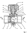
- FIG. 1 shows a longitudinal sectional view along the longitudinal axis L of the exemplified shut-off valve, which comprises as essential components a one-piece valve body 2, a screwed therein valve head 4, a substantially C-shaped valve body 6 and a sealing member 8 which is sealingly inserted into the valve body 2 and already with the valve body 6 in the in FIG. 1 cooperates shown closed position.
- Valve shell 4 shown in detail has at its one end an engagement opening 10 with a rectangular base (see. FIG. 7 ) formed as part of an eye 12 provided at one end 12.
- This eye 14 is formed by a substantially parallel to the longitudinal axis L extending web 16 of the valve body 6.
- a web 20 which is surmounted on the outside by a hemispherical bearing pin 22 which forms a substantially hemispherical outer peripheral surface.
- the fitting housing 2 forms a bearing socket 24, in which the bearing pin 22 is held in the manner of a ball joint.
- valve body 6 Between the two ends 12, 18 of the valve body 6 forms a cross-sectionally annular portion 26 which forms a concave inner peripheral portion 28 on the inside and a convex outer peripheral portion 30 on the outside.
- the outer peripheral portion 30 is additionally curved in the other direction, that is, spherically shaped to form a spherical surface segment-like sealing surface 32, whereas the inner peripheral portion 28 is rectilinearly formed in the cross-sectional views parallel to the longitudinal axis L of the valve body 2 having a rectilinear inner surface 34 cylindrical flow passage 36 continue through the fitting housing 2 without heels.
- FIG. 7 clarifies the curvature of the sealing surface 32 in a cross-sectional view at right angles to a pivot axis S for the valve body 6.
- the sealing surface 32 is completed by a dot-dash area K of a circle whose center lies on the pivot axis S.
- an envelope H is drawn, which envelops the valve body 6 at the level of the longitudinal axis L, ie at its widest point.
- This envelope H corresponds to the minimum diameter of an insertion opening 38, which is recessed on the valve housing 2 for screwing the valve upper part 4.
- the valve head 4 has a handwheel 40 in a manner known per se, which is connected rotationally fixedly with an adjusting spindle 42.
- This adjusting spindle 42 is mounted as a non-rising spindle in a valve shell housing 44 and fixed in the axial direction via a collar 46 and a snap ring 48.
- the adjusting spindle 42 a External thread 50, which cooperates with an actuating element 52, which has an internal thread 54 for this purpose.
- FIGS. 8 and 9 Details of this control element 52 are in FIGS. 8 and 9 shown.
- An end of the adjusting element 52 directed towards the valve upper part 4 is formed as a cylindrical section 56 with said internal thread 54.
- On the front side of this cylindrical section 56 there is a positive locking element 58 integrally formed on the adjusting element 52, which is formed with a rectangular cross-sectional area and three parallel to each Pivoting axis S formed form-fitting surfaces 60 and has a ramp 62 through which an obliquely to the pivot axis S extending inclined surface 64 is formed, which is inclined to the free end of the positive locking element 58 inwardly.
- the engagement opening 10 has a mating surface 66.
- This mating surface 66 is formed at the same inclination relative to the pivot axis S as the inclined surface 64.
- the inclined surface 64 and the mating surface 66 are preferably at an angle of between 10 ° and 20 ° preferably from between 12 ° and 17 ° relative to the pivot axis S employed.
- the adjusting element 52 is sealingly held in the upper valve housing 44.
- the upper valve housing 44 is sealed relative to the valve body 2.
- the fitting housing 2 has, in a manner known per se, connecting stubs 72, 74 extending parallel to one another and continuing the flow passage 36, which are in the present case formed with external threads for connection to a pipeline system.
- the connecting piece 72 is associated with the sealing element 8.
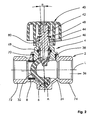
- FIG. 1 shows the closed state in which the valve body 6 at a first stop 76 (see. FIG. 3 ) is applied, which limits the pivoting movement of the valve body 6 on one side.
- FIG. 3 also shows a further stop 78, which limits the pivoting movement of the valve body 6 in the open position and determines the open position.
- This pivoting movement is mediated by cooperation of the form-locking surfaces 16 with the mating surfaces formed corresponding thereto and delimiting the engagement opening 10. Accordingly, the rotational movement of the handwheel 40 initially leads to a rotational movement of the adjusting spindle 42 and a rotational movement of the adjusting element 52. As the rotational movement of the adjusting spindle 42 and contact of the valve body 6 against the stop 76 in a rotational movement on the handwheel 40 closing the valve, a further rotational movement of Stellenses 52 impeded by the positive engagement of the same in the engagement opening 10. Accordingly, the adjusting element 52 increases in the direction of the pivot axis S. In this case, the inclined surface 74 slides past the counter surface 66.
- the inner surface 34 opposite and formed by the fitting housing 2 wall may also be formed to extend in a straight line parallel to the longitudinal axis L, so that there is a relatively low-loss flow through the shut-off valve.
- the handwheel 40 In the open position, the handwheel 40 has been rotated until the collar 46 abuts against the free end of the valve shell 44 with the interposition of a damping ring 80.
- the fitting housing is rotationally symmetrical relative to the pivot axis S (see. FIGS. 3, 5 ).
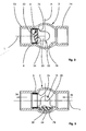
- the particular embodiment of the sealing element 8, however, also allows a sealing element 8 in the open position (see. FIG. 5 ) opposite wall of the fitting housing 2, the inner walls of the connecting pieces 72, 74 continue to form substantially rectilinear.
- FIG. 5 symmetrical embodiment, in which the inner surface 34 is formed corresponding to an opposite thereto formed by the valve housing 2 wall of the housing.
- the valve body 6 opposite Side can be dispensed with a feed between the connecting piece 74 and the central region of the valve body 2 for connecting the flow resistance through the valve.
Landscapes
- Engineering & Computer Science (AREA)
- General Engineering & Computer Science (AREA)
- Mechanical Engineering (AREA)
- Taps Or Cocks (AREA)
Claims (8)
- Vanne d'arrêt avec un boîtier de vanne (2) et un corps de vanne (6) qui est monté de façon pivotante autour d'un axe de pivotement (S) dans le boîtier de vanne (2) pour fermer et ouvrir la vanne d'arrêt, constitue une surface d'étanchéité (32), et peut pivoter autour d'un autre axe de pivotement (A) qui s'étend perpendiculairement à l'axe de pivotement (S),
caractérisée
en ce que la surface d'étanchéité (32) est constituée sous forme d'un segment de surface sphérique,
en ce qu'une partie de vanne supérieure (4) est pourvue d'une broche de réglage (42) qui coopère avec un élément de réglage (52), et
en ce que l'élément de réglage (52) coopère avec le corps de vanne (6) de telle sorte que, lors d'un déplacement de réglage de la broche de réglage (42) pour fermer la vanne d'arrêt, l'élément de réglage (52) et le corps de vanne (6) sont premièrement déplacés autour de l'axe de pivotement (S) jusqu'à une butée (76) prédéfinie par une position fermée, et le corps de vanne (6) est deuxièmement positionné d'abord par un déplacement de réglage d'avancement de la broche de réglage (42) et par un déplacement de l'élément de réglage (52) le long de l'axe de pivotement (S), et finalement autour de l'autre axe de pivotement (A) pour une application étanche du corps de vanne (6) contre le boîtier de vanne (2). - Vanne d'arrêt selon la revendication 1, caractérisée en ce qu'une partie de vanne supérieure (4)
comporte un élément de réglage montant (52) qui est connecté par engagement de forme au corps de vanne (6) pour procurer le mouvement de pivotement de fermeture ou d'ouverture, et en ce que l'élément de réglage (52) ou le corps de vanne (6) forme une rampe (62) agencée en oblique par rapport à l'axe de pivotement (S), constituée de telle sorte qu'un déplacement montant de l'élément de réglage (52) applique au corps de vanne (6) le mouvement de pivotement autour de l'autre axe de pivotement (A). - Vanne d'arrêt selon la revendication 1 ou 2, caractérisée en ce que le corps de vanne (6) présente essentiellement une forme en C et est dimensionné de telle sorte qu'il peut être extrait par une ouverture d'introduction (38) du boîtier de vanne (2) constitué d'une seule pièce pour démonter une partie de vanne supérieure (4).
- Vanne d'arrêt selon la revendication 3, caractérisée en ce que le corps de vanne (6) constitue à une extrémité un élément d'engagement de forme (58) associé à la partie de vanne supérieure (4), à son extrémité opposée un pivot (22), et entre lesdites extrémités la surface d'étanchéité (32).
- Vanne d'arrêt selon la revendication 3 ou 4, caractérisée en ce que le pivot (22) comporte une surface sphérique qui est appliquée contre une cuvette de support (24) constituée avec une surface d'accouplement correspondante (66) sur le boîtier de vanne (2).
- Vanne d'arrêt selon l'une des revendications précédentes, caractérisée en ce que le boîtier de vanne (2) est constitué d'une seule pièce, et en ce qu'une partie de vanne supérieure (4) est engagée par filetage dans une ouverture d'introduction (38) constituée dans le boîtier de vanne (2), dont le diamètre est inférieur ou égal à 1,4, préférablement inférieur ou égal à 1,25, et préférablement encore inférieur ou égal à 1,15 fois le diamètre nominal des connexions (72, 74) de la vanne d'arrêt sur une conduite.
- Vanne d'arrêt selon l'une des revendications précédentes, caractérisée en ce que l'élément de réglage (52) et/ou le corps de vanne (6) sont constitués en matière plastique.
- Vanne d'arrêt selon l'une des revendications précédentes, caractérisée par un élément d'étanchéité (8) inséré dans le boîtier de vanne (2) et appuyé contre le corps de vanne (6) de manière à procurer une étanchéité en position fermée.
Applications Claiming Priority (1)
| Application Number | Priority Date | Filing Date | Title |
|---|---|---|---|
| DE202011003806U DE202011003806U1 (de) | 2011-03-11 | 2011-03-11 | Armatur |
Publications (2)
| Publication Number | Publication Date |
|---|---|
| EP2497980A1 EP2497980A1 (fr) | 2012-09-12 |
| EP2497980B1 true EP2497980B1 (fr) | 2013-07-24 |
Family
ID=45811264
Family Applications (1)
| Application Number | Title | Priority Date | Filing Date |
|---|---|---|---|
| EP20120001402 Not-in-force EP2497980B1 (fr) | 2011-03-11 | 2012-03-01 | Armature |
Country Status (2)
| Country | Link |
|---|---|
| EP (1) | EP2497980B1 (fr) |
| DE (1) | DE202011003806U1 (fr) |
Families Citing this family (1)
| Publication number | Priority date | Publication date | Assignee | Title |
|---|---|---|---|---|
| CN109458468B (zh) * | 2018-12-25 | 2023-12-12 | 成都中科智成科技有限责任公司 | 一种无摩擦式微电机驱动的轨道球阀 |
Family Cites Families (9)
| Publication number | Priority date | Publication date | Assignee | Title |
|---|---|---|---|---|
| FR785155A (fr) * | 1934-09-21 | 1935-08-03 | Robinet à clapet à passage direct | |
| US2719022A (en) * | 1950-06-26 | 1955-09-27 | Orbit Valve Co | Valves |
| DE2501568A1 (de) * | 1975-01-16 | 1976-07-22 | Paul Drees | Ventil mit absperrelementen, die beim oeffnen zunaechst vom sitz abheben, dann in den gehaeuseraum schwenken und den durchfluss voellig freigeben |
| FR2398946A1 (fr) * | 1977-07-25 | 1979-02-23 | Bouvier Ateliers | Vanne a tournant, a passage integral |
| DE3533937C1 (de) * | 1985-09-24 | 1986-12-11 | Schertler, Siegfried, Haag | Absperrklappe nach Art eines Butterfly-Ventils |
| US5507314A (en) * | 1991-06-11 | 1996-04-16 | Masco Corporation | Mixer valve having a ball valve element |
| DK170754B1 (da) * | 1992-03-12 | 1996-01-08 | Damixa As | Etgrebsblandingsarmatur |
| GB9420533D0 (en) | 1994-10-12 | 1994-11-30 | Fort Vale Eng Ltd | Valve |
| DE202008011406U1 (de) * | 2007-12-20 | 2009-06-18 | Xomox International Gmbh & Co | Ventil |
-
2011
- 2011-03-11 DE DE202011003806U patent/DE202011003806U1/de not_active Expired - Lifetime
-
2012
- 2012-03-01 EP EP20120001402 patent/EP2497980B1/fr not_active Not-in-force
Also Published As
| Publication number | Publication date |
|---|---|
| DE202011003806U1 (de) | 2012-06-14 |
| EP2497980A1 (fr) | 2012-09-12 |
Similar Documents
| Publication | Publication Date | Title |
|---|---|---|
| EP1688654B1 (fr) | Clapet à vide | |
| EP2529136B1 (fr) | Robinet d'arrêt pour le domaine des installations de second oeuvre | |
| EP3485192B1 (fr) | Accouplement à verrouillage | |
| EP2479462B1 (fr) | Armature sanitaire antigel | |
| EP0421194B1 (fr) | Pistolet d'arrosage pour un dispositif de nettoyage à haute pression | |
| EP3139074B1 (fr) | Armature exterieure protegee contre le gel et son procede de montage | |
| DE19901654C2 (de) | Eckventil mit Rosettengriff | |
| EP2183509B1 (fr) | Dispositif de restriction de la section transversale libre d'une conduite de vapeur ou analogue | |
| EP2497980B1 (fr) | Armature | |
| EP3236121B1 (fr) | Selecteur de circuit pour un systeme de soupape de securite et systeme de soupape de securite | |
| EP2484944B1 (fr) | Corps de boîtier de soupape | |
| EP3105380A1 (fr) | Robinet à bec pivotant | |
| EP2352938B1 (fr) | Soupape à disque avec protection contre les fuites | |
| EP3105381B1 (fr) | Robinet à bec pivotant | |
| EP1462692B1 (fr) | Tête de robinet | |
| WO2020007528A1 (fr) | Partie supérieure de soupape | |
| EP2108868B1 (fr) | Robinet d'arrêt pour le domaine d'installation | |
| EP3001081B1 (fr) | Vanne équerre doté d'un volant à main | |
| EP2317193A1 (fr) | Armature sanitaire dotée d'un levier d'actionnement installé de manière déplaçable | |
| DE2850523C3 (de) | Anbohrarmatur | |
| DE102020113979B4 (de) | Verschlussmechanismus | |
| DE19842199C1 (de) | Kugelhahn | |
| DE1913968C (de) | Aus Blechformlingen hergestellte Anschlußstutzen für einen Zylinderhahn | |
| EP2884011B1 (fr) | Robinetterie sanitaire comportant une tige de robinetterie et un dispositif de fixation de la tige de robinetterie | |
| EP1128108A2 (fr) | Dispositif de raccordement sanitaire |
Legal Events
| Date | Code | Title | Description |
|---|---|---|---|
| PUAI | Public reference made under article 153(3) epc to a published international application that has entered the european phase |
Free format text: ORIGINAL CODE: 0009012 |
|
| AK | Designated contracting states |
Kind code of ref document: A1 Designated state(s): AL AT BE BG CH CY CZ DE DK EE ES FI FR GB GR HR HU IE IS IT LI LT LU LV MC MK MT NL NO PL PT RO RS SE SI SK SM TR |
|
| AX | Request for extension of the european patent |
Extension state: BA ME |
|
| 17P | Request for examination filed |
Effective date: 20121010 |
|
| RIC1 | Information provided on ipc code assigned before grant |
Ipc: F16K 5/20 20060101AFI20121211BHEP Ipc: F16K 5/06 20060101ALI20121211BHEP |
|
| GRAP | Despatch of communication of intention to grant a patent |
Free format text: ORIGINAL CODE: EPIDOSNIGR1 |
|
| GRAS | Grant fee paid |
Free format text: ORIGINAL CODE: EPIDOSNIGR3 |
|
| GRAA | (expected) grant |
Free format text: ORIGINAL CODE: 0009210 |
|
| AK | Designated contracting states |
Kind code of ref document: B1 Designated state(s): AL AT BE BG CH CY CZ DE DK EE ES FI FR GB GR HR HU IE IS IT LI LT LU LV MC MK MT NL NO PL PT RO RS SE SI SK SM TR |
|
| REG | Reference to a national code |
Ref country code: GB Ref legal event code: FG4D Free format text: NOT ENGLISH |
|
| REG | Reference to a national code |
Ref country code: CH Ref legal event code: EP Ref country code: CH Ref legal event code: NV Representative=s name: BOVARD AG, CH |
|
| REG | Reference to a national code |
Ref country code: AT Ref legal event code: REF Ref document number: 623650 Country of ref document: AT Kind code of ref document: T Effective date: 20130815 |
|
| REG | Reference to a national code |
Ref country code: IE Ref legal event code: FG4D Free format text: LANGUAGE OF EP DOCUMENT: GERMAN |
|
| REG | Reference to a national code |
Ref country code: NL Ref legal event code: T3 |
|
| REG | Reference to a national code |
Ref country code: DE Ref legal event code: R096 Ref document number: 502012000049 Country of ref document: DE Effective date: 20130919 |
|
| REG | Reference to a national code |
Ref country code: LT Ref legal event code: MG4D |
|
| PG25 | Lapsed in a contracting state [announced via postgrant information from national office to epo] |
Ref country code: SE Free format text: LAPSE BECAUSE OF FAILURE TO SUBMIT A TRANSLATION OF THE DESCRIPTION OR TO PAY THE FEE WITHIN THE PRESCRIBED TIME-LIMIT Effective date: 20130724 Ref country code: PT Free format text: LAPSE BECAUSE OF FAILURE TO SUBMIT A TRANSLATION OF THE DESCRIPTION OR TO PAY THE FEE WITHIN THE PRESCRIBED TIME-LIMIT Effective date: 20131125 Ref country code: CY Free format text: LAPSE BECAUSE OF FAILURE TO SUBMIT A TRANSLATION OF THE DESCRIPTION OR TO PAY THE FEE WITHIN THE PRESCRIBED TIME-LIMIT Effective date: 20130911 Ref country code: IS Free format text: LAPSE BECAUSE OF FAILURE TO SUBMIT A TRANSLATION OF THE DESCRIPTION OR TO PAY THE FEE WITHIN THE PRESCRIBED TIME-LIMIT Effective date: 20131124 Ref country code: HR Free format text: LAPSE BECAUSE OF FAILURE TO SUBMIT A TRANSLATION OF THE DESCRIPTION OR TO PAY THE FEE WITHIN THE PRESCRIBED TIME-LIMIT Effective date: 20130724 Ref country code: LT Free format text: LAPSE BECAUSE OF FAILURE TO SUBMIT A TRANSLATION OF THE DESCRIPTION OR TO PAY THE FEE WITHIN THE PRESCRIBED TIME-LIMIT Effective date: 20130724 Ref country code: NO Free format text: LAPSE BECAUSE OF FAILURE TO SUBMIT A TRANSLATION OF THE DESCRIPTION OR TO PAY THE FEE WITHIN THE PRESCRIBED TIME-LIMIT Effective date: 20131024 |
|
| PG25 | Lapsed in a contracting state [announced via postgrant information from national office to epo] |
Ref country code: SI Free format text: LAPSE BECAUSE OF FAILURE TO SUBMIT A TRANSLATION OF THE DESCRIPTION OR TO PAY THE FEE WITHIN THE PRESCRIBED TIME-LIMIT Effective date: 20130724 Ref country code: GR Free format text: LAPSE BECAUSE OF FAILURE TO SUBMIT A TRANSLATION OF THE DESCRIPTION OR TO PAY THE FEE WITHIN THE PRESCRIBED TIME-LIMIT Effective date: 20131025 Ref country code: PL Free format text: LAPSE BECAUSE OF FAILURE TO SUBMIT A TRANSLATION OF THE DESCRIPTION OR TO PAY THE FEE WITHIN THE PRESCRIBED TIME-LIMIT Effective date: 20130724 Ref country code: LV Free format text: LAPSE BECAUSE OF FAILURE TO SUBMIT A TRANSLATION OF THE DESCRIPTION OR TO PAY THE FEE WITHIN THE PRESCRIBED TIME-LIMIT Effective date: 20130724 Ref country code: FI Free format text: LAPSE BECAUSE OF FAILURE TO SUBMIT A TRANSLATION OF THE DESCRIPTION OR TO PAY THE FEE WITHIN THE PRESCRIBED TIME-LIMIT Effective date: 20130724 |
|
| PG25 | Lapsed in a contracting state [announced via postgrant information from national office to epo] |
Ref country code: CY Free format text: LAPSE BECAUSE OF FAILURE TO SUBMIT A TRANSLATION OF THE DESCRIPTION OR TO PAY THE FEE WITHIN THE PRESCRIBED TIME-LIMIT Effective date: 20130724 |
|
| PG25 | Lapsed in a contracting state [announced via postgrant information from national office to epo] |
Ref country code: SK Free format text: LAPSE BECAUSE OF FAILURE TO SUBMIT A TRANSLATION OF THE DESCRIPTION OR TO PAY THE FEE WITHIN THE PRESCRIBED TIME-LIMIT Effective date: 20130724 Ref country code: DK Free format text: LAPSE BECAUSE OF FAILURE TO SUBMIT A TRANSLATION OF THE DESCRIPTION OR TO PAY THE FEE WITHIN THE PRESCRIBED TIME-LIMIT Effective date: 20130724 Ref country code: CZ Free format text: LAPSE BECAUSE OF FAILURE TO SUBMIT A TRANSLATION OF THE DESCRIPTION OR TO PAY THE FEE WITHIN THE PRESCRIBED TIME-LIMIT Effective date: 20130724 Ref country code: RO Free format text: LAPSE BECAUSE OF FAILURE TO SUBMIT A TRANSLATION OF THE DESCRIPTION OR TO PAY THE FEE WITHIN THE PRESCRIBED TIME-LIMIT Effective date: 20130724 Ref country code: EE Free format text: LAPSE BECAUSE OF FAILURE TO SUBMIT A TRANSLATION OF THE DESCRIPTION OR TO PAY THE FEE WITHIN THE PRESCRIBED TIME-LIMIT Effective date: 20130724 |
|
| PG25 | Lapsed in a contracting state [announced via postgrant information from national office to epo] |
Ref country code: ES Free format text: LAPSE BECAUSE OF FAILURE TO SUBMIT A TRANSLATION OF THE DESCRIPTION OR TO PAY THE FEE WITHIN THE PRESCRIBED TIME-LIMIT Effective date: 20130724 Ref country code: IT Free format text: LAPSE BECAUSE OF FAILURE TO SUBMIT A TRANSLATION OF THE DESCRIPTION OR TO PAY THE FEE WITHIN THE PRESCRIBED TIME-LIMIT Effective date: 20130724 |
|
| PLBE | No opposition filed within time limit |
Free format text: ORIGINAL CODE: 0009261 |
|
| STAA | Information on the status of an ep patent application or granted ep patent |
Free format text: STATUS: NO OPPOSITION FILED WITHIN TIME LIMIT |
|
| 26N | No opposition filed |
Effective date: 20140425 |
|
| REG | Reference to a national code |
Ref country code: DE Ref legal event code: R097 Ref document number: 502012000049 Country of ref document: DE Effective date: 20140425 |
|
| PG25 | Lapsed in a contracting state [announced via postgrant information from national office to epo] |
Ref country code: LU Free format text: LAPSE BECAUSE OF FAILURE TO SUBMIT A TRANSLATION OF THE DESCRIPTION OR TO PAY THE FEE WITHIN THE PRESCRIBED TIME-LIMIT Effective date: 20140301 |
|
| REG | Reference to a national code |
Ref country code: FR Ref legal event code: ST Effective date: 20141128 |
|
| REG | Reference to a national code |
Ref country code: IE Ref legal event code: MM4A |
|
| PG25 | Lapsed in a contracting state [announced via postgrant information from national office to epo] |
Ref country code: FR Free format text: LAPSE BECAUSE OF NON-PAYMENT OF DUE FEES Effective date: 20140331 Ref country code: IE Free format text: LAPSE BECAUSE OF NON-PAYMENT OF DUE FEES Effective date: 20140301 |
|
| PG25 | Lapsed in a contracting state [announced via postgrant information from national office to epo] |
Ref country code: MT Free format text: LAPSE BECAUSE OF FAILURE TO SUBMIT A TRANSLATION OF THE DESCRIPTION OR TO PAY THE FEE WITHIN THE PRESCRIBED TIME-LIMIT Effective date: 20130724 |
|
| PG25 | Lapsed in a contracting state [announced via postgrant information from national office to epo] |
Ref country code: SM Free format text: LAPSE BECAUSE OF FAILURE TO SUBMIT A TRANSLATION OF THE DESCRIPTION OR TO PAY THE FEE WITHIN THE PRESCRIBED TIME-LIMIT Effective date: 20130724 |
|
| PG25 | Lapsed in a contracting state [announced via postgrant information from national office to epo] |
Ref country code: MC Free format text: LAPSE BECAUSE OF FAILURE TO SUBMIT A TRANSLATION OF THE DESCRIPTION OR TO PAY THE FEE WITHIN THE PRESCRIBED TIME-LIMIT Effective date: 20130724 |
|
| PG25 | Lapsed in a contracting state [announced via postgrant information from national office to epo] |
Ref country code: BG Free format text: LAPSE BECAUSE OF FAILURE TO SUBMIT A TRANSLATION OF THE DESCRIPTION OR TO PAY THE FEE WITHIN THE PRESCRIBED TIME-LIMIT Effective date: 20130724 Ref country code: RS Free format text: LAPSE BECAUSE OF FAILURE TO SUBMIT A TRANSLATION OF THE DESCRIPTION OR TO PAY THE FEE WITHIN THE PRESCRIBED TIME-LIMIT Effective date: 20130724 |
|
| PG25 | Lapsed in a contracting state [announced via postgrant information from national office to epo] |
Ref country code: HU Free format text: LAPSE BECAUSE OF FAILURE TO SUBMIT A TRANSLATION OF THE DESCRIPTION OR TO PAY THE FEE WITHIN THE PRESCRIBED TIME-LIMIT; INVALID AB INITIO Effective date: 20120301 Ref country code: BE Free format text: LAPSE BECAUSE OF FAILURE TO SUBMIT A TRANSLATION OF THE DESCRIPTION OR TO PAY THE FEE WITHIN THE PRESCRIBED TIME-LIMIT Effective date: 20140331 Ref country code: TR Free format text: LAPSE BECAUSE OF FAILURE TO SUBMIT A TRANSLATION OF THE DESCRIPTION OR TO PAY THE FEE WITHIN THE PRESCRIBED TIME-LIMIT Effective date: 20130724 |
|
| GBPC | Gb: european patent ceased through non-payment of renewal fee |
Effective date: 20160301 |
|
| PG25 | Lapsed in a contracting state [announced via postgrant information from national office to epo] |
Ref country code: GB Free format text: LAPSE BECAUSE OF NON-PAYMENT OF DUE FEES Effective date: 20160301 |
|
| PGFP | Annual fee paid to national office [announced via postgrant information from national office to epo] |
Ref country code: CH Payment date: 20170323 Year of fee payment: 6 Ref country code: NL Payment date: 20170323 Year of fee payment: 6 |
|
| PGFP | Annual fee paid to national office [announced via postgrant information from national office to epo] |
Ref country code: AT Payment date: 20170330 Year of fee payment: 6 |
|
| PGFP | Annual fee paid to national office [announced via postgrant information from national office to epo] |
Ref country code: DE Payment date: 20170328 Year of fee payment: 6 |
|
| PG25 | Lapsed in a contracting state [announced via postgrant information from national office to epo] |
Ref country code: MK Free format text: LAPSE BECAUSE OF FAILURE TO SUBMIT A TRANSLATION OF THE DESCRIPTION OR TO PAY THE FEE WITHIN THE PRESCRIBED TIME-LIMIT Effective date: 20130724 |
|
| REG | Reference to a national code |
Ref country code: DE Ref legal event code: R119 Ref document number: 502012000049 Country of ref document: DE |
|
| PG25 | Lapsed in a contracting state [announced via postgrant information from national office to epo] |
Ref country code: AL Free format text: LAPSE BECAUSE OF FAILURE TO SUBMIT A TRANSLATION OF THE DESCRIPTION OR TO PAY THE FEE WITHIN THE PRESCRIBED TIME-LIMIT Effective date: 20130724 |
|
| REG | Reference to a national code |
Ref country code: CH Ref legal event code: PL |
|
| REG | Reference to a national code |
Ref country code: NL Ref legal event code: MM Effective date: 20180401 |
|
| REG | Reference to a national code |
Ref country code: AT Ref legal event code: MM01 Ref document number: 623650 Country of ref document: AT Kind code of ref document: T Effective date: 20180301 |
|
| PG25 | Lapsed in a contracting state [announced via postgrant information from national office to epo] |
Ref country code: NL Free format text: LAPSE BECAUSE OF NON-PAYMENT OF DUE FEES Effective date: 20180401 |
|
| PG25 | Lapsed in a contracting state [announced via postgrant information from national office to epo] |
Ref country code: DE Free format text: LAPSE BECAUSE OF NON-PAYMENT OF DUE FEES Effective date: 20181002 Ref country code: AT Free format text: LAPSE BECAUSE OF NON-PAYMENT OF DUE FEES Effective date: 20180301 |
|
| PG25 | Lapsed in a contracting state [announced via postgrant information from national office to epo] |
Ref country code: LI Free format text: LAPSE BECAUSE OF NON-PAYMENT OF DUE FEES Effective date: 20180331 Ref country code: CH Free format text: LAPSE BECAUSE OF NON-PAYMENT OF DUE FEES Effective date: 20180331 |