EP2497975B1 - Verschleißausgleichsvorrichtung für ein Getriebe - Google Patents
Verschleißausgleichsvorrichtung für ein Getriebe Download PDFInfo
- Publication number
- EP2497975B1 EP2497975B1 EP12158024.5A EP12158024A EP2497975B1 EP 2497975 B1 EP2497975 B1 EP 2497975B1 EP 12158024 A EP12158024 A EP 12158024A EP 2497975 B1 EP2497975 B1 EP 2497975B1
- Authority
- EP
- European Patent Office
- Prior art keywords
- eccentric
- fixed support
- bearing
- gear
- torsion spring
- Prior art date
- Legal status (The legal status is an assumption and is not a legal conclusion. Google has not performed a legal analysis and makes no representation as to the accuracy of the status listed.)
- Active
Links
- 230000007246 mechanism Effects 0.000 claims description 8
- 238000005096 rolling process Methods 0.000 claims description 7
- 230000000903 blocking effect Effects 0.000 claims description 4
- 230000036316 preload Effects 0.000 claims description 3
- 230000006835 compression Effects 0.000 description 2
- 238000007906 compression Methods 0.000 description 2
- 238000002788 crimping Methods 0.000 description 1
- 238000003780 insertion Methods 0.000 description 1
- 230000037431 insertion Effects 0.000 description 1
- 230000014759 maintenance of location Effects 0.000 description 1
- 238000004519 manufacturing process Methods 0.000 description 1
- 238000000034 method Methods 0.000 description 1
- 238000000465 moulding Methods 0.000 description 1
- 239000002245 particle Substances 0.000 description 1
- 238000003825 pressing Methods 0.000 description 1
- 229920002994 synthetic fiber Polymers 0.000 description 1
- 238000004804 winding Methods 0.000 description 1
Images


Classifications
-
- F—MECHANICAL ENGINEERING; LIGHTING; HEATING; WEAPONS; BLASTING
- F16—ENGINEERING ELEMENTS AND UNITS; GENERAL MEASURES FOR PRODUCING AND MAINTAINING EFFECTIVE FUNCTIONING OF MACHINES OR INSTALLATIONS; THERMAL INSULATION IN GENERAL
- F16H—GEARING
- F16H55/00—Elements with teeth or friction surfaces for conveying motion; Worms, pulleys or sheaves for gearing mechanisms
- F16H55/02—Toothed members; Worms
- F16H55/22—Toothed members; Worms for transmissions with crossing shafts, especially worms, worm-gears
- F16H55/24—Special devices for taking up backlash
-
- F—MECHANICAL ENGINEERING; LIGHTING; HEATING; WEAPONS; BLASTING
- F16—ENGINEERING ELEMENTS AND UNITS; GENERAL MEASURES FOR PRODUCING AND MAINTAINING EFFECTIVE FUNCTIONING OF MACHINES OR INSTALLATIONS; THERMAL INSULATION IN GENERAL
- F16H—GEARING
- F16H57/00—General details of gearing
- F16H57/02—Gearboxes; Mounting gearing therein
- F16H57/021—Shaft support structures, e.g. partition walls, bearing eyes, casing walls or covers with bearings
- F16H57/022—Adjustment of gear shafts or bearings
-
- F—MECHANICAL ENGINEERING; LIGHTING; HEATING; WEAPONS; BLASTING
- F16—ENGINEERING ELEMENTS AND UNITS; GENERAL MEASURES FOR PRODUCING AND MAINTAINING EFFECTIVE FUNCTIONING OF MACHINES OR INSTALLATIONS; THERMAL INSULATION IN GENERAL
- F16H—GEARING
- F16H1/00—Toothed gearings for conveying rotary motion
- F16H1/02—Toothed gearings for conveying rotary motion without gears having orbital motion
- F16H1/04—Toothed gearings for conveying rotary motion without gears having orbital motion involving only two intermeshing members
- F16H1/12—Toothed gearings for conveying rotary motion without gears having orbital motion involving only two intermeshing members with non-parallel axes
- F16H1/16—Toothed gearings for conveying rotary motion without gears having orbital motion involving only two intermeshing members with non-parallel axes comprising worm and worm-wheel
-
- F—MECHANICAL ENGINEERING; LIGHTING; HEATING; WEAPONS; BLASTING
- F16—ENGINEERING ELEMENTS AND UNITS; GENERAL MEASURES FOR PRODUCING AND MAINTAINING EFFECTIVE FUNCTIONING OF MACHINES OR INSTALLATIONS; THERMAL INSULATION IN GENERAL
- F16H—GEARING
- F16H57/00—General details of gearing
- F16H57/02—Gearboxes; Mounting gearing therein
- F16H57/021—Shaft support structures, e.g. partition walls, bearing eyes, casing walls or covers with bearings
- F16H2057/0213—Support of worm gear shafts
-
- F—MECHANICAL ENGINEERING; LIGHTING; HEATING; WEAPONS; BLASTING
- F16—ENGINEERING ELEMENTS AND UNITS; GENERAL MEASURES FOR PRODUCING AND MAINTAINING EFFECTIVE FUNCTIONING OF MACHINES OR INSTALLATIONS; THERMAL INSULATION IN GENERAL
- F16H—GEARING
- F16H57/00—General details of gearing
- F16H57/02—Gearboxes; Mounting gearing therein
- F16H57/021—Shaft support structures, e.g. partition walls, bearing eyes, casing walls or covers with bearings
- F16H57/022—Adjustment of gear shafts or bearings
- F16H2057/0222—Lateral adjustment
- F16H2057/0224—Lateral adjustment using eccentric bushes
-
- Y—GENERAL TAGGING OF NEW TECHNOLOGICAL DEVELOPMENTS; GENERAL TAGGING OF CROSS-SECTIONAL TECHNOLOGIES SPANNING OVER SEVERAL SECTIONS OF THE IPC; TECHNICAL SUBJECTS COVERED BY FORMER USPC CROSS-REFERENCE ART COLLECTIONS [XRACs] AND DIGESTS
- Y10—TECHNICAL SUBJECTS COVERED BY FORMER USPC
- Y10T—TECHNICAL SUBJECTS COVERED BY FORMER US CLASSIFICATION
- Y10T74/00—Machine element or mechanism
- Y10T74/19—Gearing
- Y10T74/19619—Displaceable elements
-
- Y—GENERAL TAGGING OF NEW TECHNOLOGICAL DEVELOPMENTS; GENERAL TAGGING OF CROSS-SECTIONAL TECHNOLOGIES SPANNING OVER SEVERAL SECTIONS OF THE IPC; TECHNICAL SUBJECTS COVERED BY FORMER USPC CROSS-REFERENCE ART COLLECTIONS [XRACs] AND DIGESTS
- Y10—TECHNICAL SUBJECTS COVERED BY FORMER USPC
- Y10T—TECHNICAL SUBJECTS COVERED BY FORMER US CLASSIFICATION
- Y10T74/00—Machine element or mechanism
- Y10T74/19—Gearing
- Y10T74/19642—Directly cooperating gears
- Y10T74/19698—Spiral
- Y10T74/19828—Worm
Definitions
- the present invention relates to the field of wear-compensation devices for gear, notably used in assisted-steering mechanisms for motor vehicles.
- An assisted-steering mechanism usually comprises an electric assistance motor and a worm mounted on an output shaft of the said motor and meshing with a toothed wheel for example fixed to the shaft of the steering column or connected to the steering rack via an intermediate pinion.
- Patent US-B1-6,763,738 discloses an assisted-steering mechanism for a motor vehicle comprising means for adjusting the distance separating the axes of the worm and of the associated toothed wheel so as to be able to adjust the clearance that exists between the teeth of the gear during assembly.
- This assisted-steering mechanism comprises no means to limit the phenomena of wear of the gear set over time.
- DE 100 53183 which constitutes the closest prior art, discloses an apparatus for controlling the clearance between teeth of a worm gear which mesh with teeth of a worm wheel.
- the apparatus comprises a rotatable eccentric, a housing, a torsion spring, a blocking member and a threaded plug closing a housing chamber in which said eccentric, blocking member and torsion spring are located.
- One end of the torsion spring is positioned in a slot provided on the eccentric. The other end is located in a slot provided in the anti-rotation member.
- one end of the worm connected to the electric assistance motor is mounted rotatably in an eccentric bore of a movable sleeve, the said sleeve being connected to a compression spring.
- the compression spring causes the sleeve to rotate inside the associated housing. This gives an automatic compensation for the wear of the gear.
- the object of the present invention is to overcome this drawback.
- the object of the present invention is to provide a wear-compensation device for a gear easy to manufacture, to install, having a restricted space requirement and economic.
- the wear-compensation device for a gear comprises a fixed support capable of being fixed axially on an external element in order to keep the device on the said external element, a bearing designed to be mounted on a shaft comprising one of the wheels of the gear, and an eccentric mounted on the bearing and designed to be in contact with the external element, the said eccentric being able to move angularly relative to the fixed support.
- the device comprises a torsion spring mounted axially between the fixed support and the eccentric and capable of exerting a circumferential preload force on the said eccentric.
- the torsion spring comprises a first end mounted inside a recess of the eccentric and a second end abutting against a bearing lug of the fixed support.
- a radial wall of the fixed support and the eccentric may delimit an axial space in which the torsion spring is placed.
- the fixed support comprises a centring portion for centring the torsion spring.
- the torsion spring is coaxial with the bearing.
- the fixed support comprises clip fastening means adapted to ensure the axial attachment of the device to the external element.
- the fixed support may comprise a rotation blocking means capable of maintaining the predetermined angular position of the said support relative to the external element.
- the bearing comprises an inner ring designed to be mounted on said shaft supporting one of the wheels of the gear, an outer ring on which the eccentric is mounted, and at least one row of rolling elements placed between the said rings.
- the bearing may be a sliding bearing.
- the wheel is integrally formed on said shaft.
- the wheel may be integrally formed on said shaft so as to form a screw.
- the invention also relates to an assisted-steering mechanism for a motor vehicle comprising a wear-compensation device as defined above.
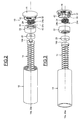
- a wear-compensation device referenced 10 in its entirety, is associated with a gear of the type with a wheel 12 and with a worm 14.
- the gear illustrated is a crossed gear set and the axes 12a, 14a of the toothed gear and of the worm are orthogonal.
- the device 10 comprises a fixed support 16 forming a cap designed to be mounted on a tubular housing 18 external to the said device, a rolling bearing 20 mounted on an end trunnion 14b of the worm, an eccentric 22 mounted on the rolling bearing, and a torsion spring 24 capable of applying a permanent circumferential force between the support 16 and the said eccentric.
- the worm 14 extends axially in the housing 18, the said housing comprising an opening 18a allowing the passage of the toothed wheel 12 so that the thread or threads of the worm mesh with the teeth of the wheel.
- the bearing 20 (shown schematically) has a rotation axis 20a coaxial with the axis 14a of the worm. It comprises an inner ring mounted tightly on the trunnion 14b of the said worm and butting axially against a shoulder of the trunnion, an outer ring on which the eccentric 22 is mounted, a row of rolling elements, for example balls, and seals mounted radially between the said rings.
- the fixed support 16 comprises a radial wall 26 closing off an axial end of the housing 18 and extended by an annular centring portion 28, coaxial with the axis 20a of the bearing and pressing axially against the inner ring of the said bearing.
- the centring portion 28 comprises a blind hole 30 inside which the trunnion 14b of the worm extends with a radial clearance.
- the support 16 also comprises a plurality of axial lugs 32 extending from the wall 26 axially on the side of the centring portion 28.
- the lugs 32 are spaced relative to one another in the circumferential direction.
- Each lug 32 comprises, at its free end, a hook extending radially outwards and designed to interact with a matching recess arranged in the bore of the housing 18.
- the lugs 32 form snap-fitting or clip fastening means for fitting the support 16 to the housing making it possible to obtain the axial attachment of these two elements.
- the support 16 may for example be made in a single piece
- the eccentric 22 comprises a cylindrical bore 34 inside which is tightly mounted the outer ring of the bearing 20 and a cylindrical external surface 36, with an axis 36a which is radially offset relative to the axis 20a of the bearing.
- the bore 34 comprises a radial protuberance (not referenced) extending inwards and forming an axial stopping surface for the outer ring of the bearing 20.
- the external surface 36 of the eccentric presses radially against a matching cylindrical bearing surface 38 of the bore of the housing 18.
- the eccentric 22 can move angularly relative to the fixed support 16, to the housing 18 and to the worm 14.
- the turns of the spring 24 have, in cross section, a square profile. Alternatively, it is of course possible to provide turns having another profile, for example circular.
- the device 10 also comprises an annular seal 42 mounted radially between the lugs 32 of the fixed support and the bore of the housing 18 so as to limit the intrusion of contaminating particles.
- the procedure is as follows.
- the subassembly formed by the rolling bearing 20 and the eccentric 22 is mounted on the trunnion 14b of the worm, the external surface 36 of the said eccentric being in radial contact against the cylindrical bearing surface 38 of the housing 18.
- the end 24a of the torsion spring is mounted in the recess 40 of the eccentric and the opposite end of the spring against the associated bearing lug 32 of the support 16.
- the support 16 is made to pivot relative to the eccentric 22, to the worm 14 and to the housing 18 so as to prestress or preload the spring 24 between the support and the eccentric.
- the support is prevented from rotating, for example by hammering or crimping, the axial retention of the said support on the housing being achieved by the lugs 32.
- the spring 24 thus exerts a permanent circumferential force or torque on the eccentric 22 tending to permanently push the said eccentric, the bearing 20 and the worm 14 radially towards the wheel 12. This makes it possible to automatically compensate for the wear of the thread or threads of the worm 14 and/or of the teeth of the wheel 12 that may appear over time.
- the permanent circumferential force exerted by the spring 24 on the eccentric 22 makes it possible to obtain the angular movement of the said eccentric relative to the housing 18 and to the support 16, which causes a radial movement of the rolling bearing 20 and of the worm 14 towards the wheel 12.
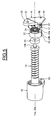
- the support 16 comprises a first radial protuberance 50 comprising a hollow cavity 52 provided for the housing, during assembly, of an operating key (not shown) in order to make it easier to pivot the support 16 for preloading the spring 24.
- the support 16 also comprises a second radial protuberance 54 opposite to the protuberance 50 and provided with a through recess 56.
- the housing 18 comprises a radial ear 58 against which the protuberance 54 rests and provided with a recess 60.
- the wear-compensation device is used for a gear of the type with a wheel and with a worm that can be installed in an assisted-steering mechanism.
- the device may however be used for other types of crossed or non-crossed gear sets, for example a gear of toothed wheels, a gear of bevel pinions, a gear with a wheel and with a rack, and be used in other applications.
Landscapes
- Engineering & Computer Science (AREA)
- General Engineering & Computer Science (AREA)
- Mechanical Engineering (AREA)
- Gear Transmission (AREA)
- Power Steering Mechanism (AREA)
Claims (10)
- Verschleißausgleichsvorrichtung für ein Getriebe, die Folgendes umfasst:eine feststehende Stütze (16), die dazu in der Lage ist, in Axialrichtung an einem äußeren Element (18) fixiert zu werden, um die Vorrichtung an dem äußeren Element zu halten,- ein Lager (20), das dafür ausgelegt ist, an einer Welle (14a, 14b) angebracht zu werden, die eines der Räder des Getriebes (14) umfasst,- einen Exzenter (22), der an dem Lager (20) angebracht und dafür ausgelegt ist, sich in Berührung mit dem äußeren Element (18) zu befinden, wobei der Exzenter dazu in der Lage ist, sich winklig im Verhältnis zu der feststehenden Stütze (16) zu bewegen, und- eine Torsionsfeder (24), die in Axialrichtung zwischen der feststehenden Stütze (16) und dem Exzenter (22) angebracht und dazu in der Lage ist, eine umlaufende Vorbelastungskraft auf den Exzenter (22) auszuüben, wobei die Feder (24) ein erstes Ende umfasst, das innerhalb einer Aussparung (40) des Exzenters (22) angebracht ist, dadurch gekennzeichnet, dass die Torsionsfeder (24) ein zweites Ende umfasst, das an einen Lagerbock (32) der feststehenden Stütze (16) anstößt.
- Vorrichtung nach Anspruch 1, wobei eine radiale Wand (26) der feststehenden Stütze und der Exzenter (22) einen axialen Raum begrenzen, in dem die Torsionsfeder (24) platziert ist.
- Vorrichtung nach Anspruch 1 oder 2, wobei die feststehende Stütze (16) einen Zentrierabschnitt (28) zum Zentrieren der Torsionsfeder umfasst.
- Vorrichtung nach einem der vorhergehenden Ansprüche, wobei die Torsionsfeder (24) koaxial mit dem Lager (20) ist.
- Vorrichtung nach einem der vorhergehenden Ansprüche, wobei die feststehende Stütze (16) Rastbefestigungsmittel (32) umfasst, die dafür eingerichtet sind, die axiale Befestigung der Vorrichtung an dem äußeren Element (18) sicherzustellen.
- Vorrichtung nach einem der vorhergehenden Ansprüche, wobei die feststehende Stütze (16) ein Drehungssperrmittel (62) umfasst, das dazu in der Lage ist, die vorbestimmte Winkelstellung der Stütze (16) im Verhältnis zu dem äußeren Element (18) aufrechtzuerhalten.
- Vorrichtung nach einem der vorhergehenden Ansprüche, wobei das Lager (20) einen inneren Ring, der dafür ausgelegt ist, an der Welle (14b) angebracht zu werden, die eines der Räder (14) des Getriebes trägt, einen äußeren Ring, an dem der Exzenter (22) angebracht ist, und wenigstens eine Reihe von Wälzelementen, die zwischen den Ringen. angeordnet sind, umfasst.
- Vorrichtung nach einem der vorhergehenden Ansprüche, wobei das Rad (14) integral an der Welle (14b) geformt ist.
- Vorrichtung nach Anspruch 8, wobei das Rad integral an der Welle (14b) geformt ist, so dass es eine Schraube (14) bildet.
- Lenkhilfemechanismus für ein Kraftfahrzeug, der eine Verschleißausgleichsvorrichtung nach einem der vorhergehenden Ansprüche umfasst,
Applications Claiming Priority (1)
| Application Number | Priority Date | Filing Date | Title |
|---|---|---|---|
| FR1151933A FR2972514B1 (fr) | 2011-03-09 | 2011-03-09 | Dispositif de compensation d'usure pour engrenage. |
Publications (2)
| Publication Number | Publication Date |
|---|---|
| EP2497975A1 EP2497975A1 (de) | 2012-09-12 |
| EP2497975B1 true EP2497975B1 (de) | 2014-06-25 |
Family
ID=44357960
Family Applications (1)
| Application Number | Title | Priority Date | Filing Date |
|---|---|---|---|
| EP12158024.5A Active EP2497975B1 (de) | 2011-03-09 | 2012-03-05 | Verschleißausgleichsvorrichtung für ein Getriebe |
Country Status (4)
| Country | Link |
|---|---|
| US (1) | US8950280B2 (de) |
| EP (1) | EP2497975B1 (de) |
| CN (1) | CN102678883B (de) |
| FR (1) | FR2972514B1 (de) |
Families Citing this family (26)
| Publication number | Priority date | Publication date | Assignee | Title |
|---|---|---|---|---|
| US8905185B2 (en) * | 2009-12-23 | 2014-12-09 | Mando Corporation | Reducer of electric power steering apparatus |
| DE102012103146A1 (de) * | 2012-04-12 | 2013-10-17 | Zf Lenksysteme Gmbh | Lenkgetriebe |
| FR2989755B1 (fr) * | 2012-04-23 | 2015-01-16 | Skf Ab | Dispositif de compensation d'usure pour engrenage et procede de montage associe. |
| US9533701B2 (en) | 2012-08-07 | 2017-01-03 | Steering Solutions Ip Holding Corporation | Steering column assist system |
| US9664273B2 (en) * | 2012-08-07 | 2017-05-30 | Steering Solutions Ip Holding Corporation | Steering column assist system |
| DE102013223380A1 (de) * | 2013-01-10 | 2014-07-10 | Ford Global Technologies, Llc | Elektrische Servolenkung für Fahrzeuge |
| CN104823367B (zh) * | 2013-02-28 | 2017-07-04 | 日本电产三协株式会社 | 马达装置 |
| US9227652B2 (en) * | 2013-03-12 | 2016-01-05 | Steering Solutions Ip Holding Corporation | Rack and pinion wear compensation |
| DE102013207142B4 (de) * | 2013-04-19 | 2014-12-11 | Ford Global Technologies, Llc | Schneckengetriebe |
| DE102013007883A1 (de) | 2013-05-08 | 2014-11-13 | Thyssenkrupp Presta Ag | Anfederungs-Exzenterschwinge in CEPS-Anwendung |
| DE102013010361A1 (de) * | 2013-06-21 | 2014-12-24 | Thyssenkrupp Presta Ag | Spielausgleich für eine Ritzellagerung |
| CN103639710A (zh) * | 2013-12-18 | 2014-03-19 | 周永林 | 高精度无间隙传动数控转台 |
| DE102014110306A1 (de) * | 2014-07-22 | 2016-01-28 | Thyssenkrupp Ag | Elektromechanische Servolenkung |
| EP3056767A1 (de) * | 2015-02-13 | 2016-08-17 | IMS Gear GmbH | Kunststoffelement zur spielfreien Lagerung |
| GB201502825D0 (en) * | 2015-02-19 | 2015-04-08 | Trw Ltd | Gearbox for electric assisted steering apparatus |
| GB201504960D0 (en) * | 2015-03-24 | 2015-05-06 | Trw Ltd | A gearbox assembly for an electric power steering assembly |
| JP6569892B2 (ja) * | 2015-04-30 | 2019-09-04 | 株式会社ジェイテクト | ウォーム減速機およびステアリング装置 |
| CN104930177A (zh) * | 2015-05-28 | 2015-09-23 | 常州华达科捷光电仪器有限公司 | 一种用于消除齿轮间隙的结构 |
| CN104930161A (zh) * | 2015-05-28 | 2015-09-23 | 常州华达科捷光电仪器有限公司 | 一种微调结构 |
| WO2017002393A1 (ja) * | 2015-06-29 | 2017-01-05 | 日本精工株式会社 | ウォーム減速機 |
| US10160479B2 (en) | 2015-07-09 | 2018-12-25 | Steering Solutions Ip Holding Corporation | Eccentric adjustment retainer |
| DE102016223833A1 (de) * | 2016-11-30 | 2018-05-30 | Zf Friedrichshafen Ag | Verschleißausgleich für gleitgelagerte Wellen |
| JPWO2019017397A1 (ja) * | 2017-07-19 | 2020-04-02 | 日本精工株式会社 | ウォーム減速機 |
| DE102018106025A1 (de) | 2018-03-15 | 2019-09-19 | Thyssenkrupp Ag | Schraubradgetriebe für eine elektromechanische Servolenkung mit einem asymmetrisch vorgespannten Festlager |
| WO2019181288A1 (ja) * | 2018-03-19 | 2019-09-26 | アルプスアルパイン株式会社 | 入力装置 |
| CN109681623A (zh) * | 2019-03-07 | 2019-04-26 | 青岛麦科三维测控技术股份有限公司 | 一种用于齿轮齿条传动的间隙消除装置 |
Family Cites Families (14)
| Publication number | Priority date | Publication date | Assignee | Title |
|---|---|---|---|---|
| JPS61241267A (ja) * | 1985-04-19 | 1986-10-27 | Jidosha Kiki Co Ltd | 電動式動力舵取装置 |
| GB9718574D0 (en) * | 1997-09-03 | 1997-11-05 | Lucas Ind Plc | Improvements relating to gears |
| JP4221825B2 (ja) | 1999-06-28 | 2009-02-12 | 株式会社ジェイテクト | 電動式舵取装置 |
| US6269709B1 (en) * | 1999-11-02 | 2001-08-07 | Trw Inc. | Apparatus for automatic control of the clearance between gears |
| FR2808759B1 (fr) * | 2000-05-10 | 2005-08-26 | Koyo Seiko Co | Appareil de direction assistee electrique |
| EP1452419B1 (de) * | 2001-12-03 | 2010-07-14 | Nsk Ltd., | Elektrische servolenkvorrichtung |
| JP2004156740A (ja) * | 2002-11-07 | 2004-06-03 | Matsushita Electric Ind Co Ltd | 歯車装置及びディスク装置 |
| WO2004052712A1 (ja) * | 2002-12-09 | 2004-06-24 | Nsk Ltd. | 電動パワーステアリング装置 |
| JP4716679B2 (ja) * | 2003-06-25 | 2011-07-06 | 日本精工株式会社 | ウォーム減速機及び電動式パワーステアリング装置 |
| CN2830796Y (zh) * | 2005-08-05 | 2006-10-25 | 江门联和发动机有限公司 | 一种组合式平衡轴齿轮 |
| KR100621347B1 (ko) * | 2005-09-20 | 2006-09-07 | 주식회사 만도 | 자동차의 전기식 동력 보조 조향 장치 |
| JP4872372B2 (ja) * | 2006-02-14 | 2012-02-08 | 株式会社ジェイテクト | 電動パワーステアリング装置 |
| JP4914810B2 (ja) * | 2007-11-21 | 2012-04-11 | 本田技研工業株式会社 | シザース歯車の組立方法及び噛み合い組付治具 |
| US8307938B2 (en) * | 2009-01-22 | 2012-11-13 | Showa Corporation | Electric power steering apparatus |
-
2011
- 2011-03-09 FR FR1151933A patent/FR2972514B1/fr not_active Expired - Fee Related
-
2012
- 2012-03-05 EP EP12158024.5A patent/EP2497975B1/de active Active
- 2012-03-08 US US13/415,099 patent/US8950280B2/en active Active
- 2012-03-09 CN CN201210131200.1A patent/CN102678883B/zh active Active
Also Published As
| Publication number | Publication date |
|---|---|
| EP2497975A1 (de) | 2012-09-12 |
| CN102678883B (zh) | 2016-08-31 |
| US20120227526A1 (en) | 2012-09-13 |
| US8950280B2 (en) | 2015-02-10 |
| CN102678883A (zh) | 2012-09-19 |
| FR2972514B1 (fr) | 2013-09-06 |
| FR2972514A1 (fr) | 2012-09-14 |
Similar Documents
| Publication | Publication Date | Title |
|---|---|---|
| EP2497975B1 (de) | Verschleißausgleichsvorrichtung für ein Getriebe | |
| US10641370B2 (en) | Ball screw | |
| EP2730483B1 (de) | Lagerbefestigungsstruktur und lenkgetriebeeinheit mit der lagerbefestigungsstruktur | |
| EP2684771B1 (de) | Zahnstangentragevorrichtung und Lenksystem damit | |
| KR20100120271A (ko) | 롤러 블라인드를 작동시키기 위한 관형 액추에이터 | |
| US8640567B2 (en) | Steering column device | |
| CN103375564A (zh) | 用于齿轮组的磨损补偿设备及其安装方法 | |
| EP2684770B1 (de) | Vorrichtung zum Andrücken einer Zahnstange gegen ein Ritzel einer Lenkgetriebeanordnung | |
| EP3549844B1 (de) | Elektrisches servolenksystem | |
| US8784253B2 (en) | Transmission ratio variable device | |
| CN103261741A (zh) | 滚珠丝杠 | |
| KR20130119369A (ko) | 기어 세트용 마모 보상 장치 및 연계된 장착 방법 | |
| US11994191B2 (en) | Planetary roller screw | |
| CN105711639A (zh) | 电动转向装置 | |
| JP2003014055A (ja) | ウォーム減速装置のバックラッシュ調整装置 | |
| JP2010210062A (ja) | ラック軸支持装置および車両用操舵装置 | |
| CN112744286B (zh) | 用于车辆的齿轮箱组件 | |
| KR102718297B1 (ko) | 스티어링 장치 | |
| JP6486089B2 (ja) | 回転伝達装置 | |
| KR20140095436A (ko) | 차량의 러닝 휠을 위한 구동 유닛 | |
| CN111919050B (zh) | 用于汽车车身水平调节机构的传动装置组件 | |
| CN109572908B (zh) | 制动装置 | |
| CN105715772B (zh) | 位置调节驱动器及其制造方法及机动车中用于其的机构 | |
| KR20140095434A (ko) | 차량의 러닝 휠을 위한 구동 유닛 | |
| EP3647156A1 (de) | Lenkgetriebe für ein fahrzeug |
Legal Events
| Date | Code | Title | Description |
|---|---|---|---|
| PUAI | Public reference made under article 153(3) epc to a published international application that has entered the european phase |
Free format text: ORIGINAL CODE: 0009012 |
|
| AK | Designated contracting states |
Kind code of ref document: A1 Designated state(s): AL AT BE BG CH CY CZ DE DK EE ES FI FR GB GR HR HU IE IS IT LI LT LU LV MC MK MT NL NO PL PT RO RS SE SI SK SM TR |
|
| AX | Request for extension of the european patent |
Extension state: BA ME |
|
| 17P | Request for examination filed |
Effective date: 20121023 |
|
| 17Q | First examination report despatched |
Effective date: 20130301 |
|
| RIC1 | Information provided on ipc code assigned before grant |
Ipc: F16H 57/12 20060101ALN20131211BHEP Ipc: F16H 1/16 20060101ALN20131211BHEP Ipc: F16H 57/02 20120101AFI20131211BHEP |
|
| GRAP | Despatch of communication of intention to grant a patent |
Free format text: ORIGINAL CODE: EPIDOSNIGR1 |
|
| INTG | Intention to grant announced |
Effective date: 20140122 |
|
| GRAS | Grant fee paid |
Free format text: ORIGINAL CODE: EPIDOSNIGR3 |
|
| GRAA | (expected) grant |
Free format text: ORIGINAL CODE: 0009210 |
|
| AK | Designated contracting states |
Kind code of ref document: B1 Designated state(s): AL AT BE BG CH CY CZ DE DK EE ES FI FR GB GR HR HU IE IS IT LI LT LU LV MC MK MT NL NO PL PT RO RS SE SI SK SM TR |
|
| REG | Reference to a national code |
Ref country code: GB Ref legal event code: FG4D |
|
| REG | Reference to a national code |
Ref country code: CH Ref legal event code: EP |
|
| REG | Reference to a national code |
Ref country code: AT Ref legal event code: REF Ref document number: 674922 Country of ref document: AT Kind code of ref document: T Effective date: 20140715 |
|
| REG | Reference to a national code |
Ref country code: IE Ref legal event code: FG4D |
|
| REG | Reference to a national code |
Ref country code: DE Ref legal event code: R096 Ref document number: 602012002176 Country of ref document: DE Effective date: 20140731 |
|
| PG25 | Lapsed in a contracting state [announced via postgrant information from national office to epo] |
Ref country code: LT Free format text: LAPSE BECAUSE OF FAILURE TO SUBMIT A TRANSLATION OF THE DESCRIPTION OR TO PAY THE FEE WITHIN THE PRESCRIBED TIME-LIMIT Effective date: 20140625 Ref country code: CY Free format text: LAPSE BECAUSE OF FAILURE TO SUBMIT A TRANSLATION OF THE DESCRIPTION OR TO PAY THE FEE WITHIN THE PRESCRIBED TIME-LIMIT Effective date: 20140625 Ref country code: GR Free format text: LAPSE BECAUSE OF FAILURE TO SUBMIT A TRANSLATION OF THE DESCRIPTION OR TO PAY THE FEE WITHIN THE PRESCRIBED TIME-LIMIT Effective date: 20140926 Ref country code: FI Free format text: LAPSE BECAUSE OF FAILURE TO SUBMIT A TRANSLATION OF THE DESCRIPTION OR TO PAY THE FEE WITHIN THE PRESCRIBED TIME-LIMIT Effective date: 20140625 Ref country code: NO Free format text: LAPSE BECAUSE OF FAILURE TO SUBMIT A TRANSLATION OF THE DESCRIPTION OR TO PAY THE FEE WITHIN THE PRESCRIBED TIME-LIMIT Effective date: 20140925 |
|
| REG | Reference to a national code |
Ref country code: AT Ref legal event code: MK05 Ref document number: 674922 Country of ref document: AT Kind code of ref document: T Effective date: 20140625 |
|
| REG | Reference to a national code |
Ref country code: NL Ref legal event code: VDEP Effective date: 20140625 |
|
| REG | Reference to a national code |
Ref country code: LT Ref legal event code: MG4D |
|
| PG25 | Lapsed in a contracting state [announced via postgrant information from national office to epo] |
Ref country code: SE Free format text: LAPSE BECAUSE OF FAILURE TO SUBMIT A TRANSLATION OF THE DESCRIPTION OR TO PAY THE FEE WITHIN THE PRESCRIBED TIME-LIMIT Effective date: 20140625 Ref country code: RS Free format text: LAPSE BECAUSE OF FAILURE TO SUBMIT A TRANSLATION OF THE DESCRIPTION OR TO PAY THE FEE WITHIN THE PRESCRIBED TIME-LIMIT Effective date: 20140625 Ref country code: HR Free format text: LAPSE BECAUSE OF FAILURE TO SUBMIT A TRANSLATION OF THE DESCRIPTION OR TO PAY THE FEE WITHIN THE PRESCRIBED TIME-LIMIT Effective date: 20140625 Ref country code: LV Free format text: LAPSE BECAUSE OF FAILURE TO SUBMIT A TRANSLATION OF THE DESCRIPTION OR TO PAY THE FEE WITHIN THE PRESCRIBED TIME-LIMIT Effective date: 20140625 |
|
| PG25 | Lapsed in a contracting state [announced via postgrant information from national office to epo] |
Ref country code: SK Free format text: LAPSE BECAUSE OF FAILURE TO SUBMIT A TRANSLATION OF THE DESCRIPTION OR TO PAY THE FEE WITHIN THE PRESCRIBED TIME-LIMIT Effective date: 20140625 Ref country code: EE Free format text: LAPSE BECAUSE OF FAILURE TO SUBMIT A TRANSLATION OF THE DESCRIPTION OR TO PAY THE FEE WITHIN THE PRESCRIBED TIME-LIMIT Effective date: 20140625 Ref country code: PT Free format text: LAPSE BECAUSE OF FAILURE TO SUBMIT A TRANSLATION OF THE DESCRIPTION OR TO PAY THE FEE WITHIN THE PRESCRIBED TIME-LIMIT Effective date: 20141027 Ref country code: CZ Free format text: LAPSE BECAUSE OF FAILURE TO SUBMIT A TRANSLATION OF THE DESCRIPTION OR TO PAY THE FEE WITHIN THE PRESCRIBED TIME-LIMIT Effective date: 20140625 Ref country code: ES Free format text: LAPSE BECAUSE OF FAILURE TO SUBMIT A TRANSLATION OF THE DESCRIPTION OR TO PAY THE FEE WITHIN THE PRESCRIBED TIME-LIMIT Effective date: 20140625 Ref country code: RO Free format text: LAPSE BECAUSE OF FAILURE TO SUBMIT A TRANSLATION OF THE DESCRIPTION OR TO PAY THE FEE WITHIN THE PRESCRIBED TIME-LIMIT Effective date: 20140625 |
|
| PG25 | Lapsed in a contracting state [announced via postgrant information from national office to epo] |
Ref country code: AT Free format text: LAPSE BECAUSE OF FAILURE TO SUBMIT A TRANSLATION OF THE DESCRIPTION OR TO PAY THE FEE WITHIN THE PRESCRIBED TIME-LIMIT Effective date: 20140625 Ref country code: PL Free format text: LAPSE BECAUSE OF FAILURE TO SUBMIT A TRANSLATION OF THE DESCRIPTION OR TO PAY THE FEE WITHIN THE PRESCRIBED TIME-LIMIT Effective date: 20140625 Ref country code: IS Free format text: LAPSE BECAUSE OF FAILURE TO SUBMIT A TRANSLATION OF THE DESCRIPTION OR TO PAY THE FEE WITHIN THE PRESCRIBED TIME-LIMIT Effective date: 20141025 Ref country code: NL Free format text: LAPSE BECAUSE OF FAILURE TO SUBMIT A TRANSLATION OF THE DESCRIPTION OR TO PAY THE FEE WITHIN THE PRESCRIBED TIME-LIMIT Effective date: 20140625 |
|
| REG | Reference to a national code |
Ref country code: DE Ref legal event code: R097 Ref document number: 602012002176 Country of ref document: DE |
|
| REG | Reference to a national code |
Ref country code: FR Ref legal event code: PLFP Year of fee payment: 4 |
|
| PG25 | Lapsed in a contracting state [announced via postgrant information from national office to epo] |
Ref country code: DK Free format text: LAPSE BECAUSE OF FAILURE TO SUBMIT A TRANSLATION OF THE DESCRIPTION OR TO PAY THE FEE WITHIN THE PRESCRIBED TIME-LIMIT Effective date: 20140625 Ref country code: IT Free format text: LAPSE BECAUSE OF FAILURE TO SUBMIT A TRANSLATION OF THE DESCRIPTION OR TO PAY THE FEE WITHIN THE PRESCRIBED TIME-LIMIT Effective date: 20140625 |
|
| PLBE | No opposition filed within time limit |
Free format text: ORIGINAL CODE: 0009261 |
|
| STAA | Information on the status of an ep patent application or granted ep patent |
Free format text: STATUS: NO OPPOSITION FILED WITHIN TIME LIMIT |
|
| 26N | No opposition filed |
Effective date: 20150326 |
|
| PG25 | Lapsed in a contracting state [announced via postgrant information from national office to epo] |
Ref country code: BE Free format text: LAPSE BECAUSE OF FAILURE TO SUBMIT A TRANSLATION OF THE DESCRIPTION OR TO PAY THE FEE WITHIN THE PRESCRIBED TIME-LIMIT Effective date: 20140625 |
|
| REG | Reference to a national code |
Ref country code: DE Ref legal event code: R097 Ref document number: 602012002176 Country of ref document: DE Effective date: 20150326 |
|
| PGFP | Annual fee paid to national office [announced via postgrant information from national office to epo] |
Ref country code: FR Payment date: 20150331 Year of fee payment: 4 |
|
| PG25 | Lapsed in a contracting state [announced via postgrant information from national office to epo] |
Ref country code: LU Free format text: LAPSE BECAUSE OF FAILURE TO SUBMIT A TRANSLATION OF THE DESCRIPTION OR TO PAY THE FEE WITHIN THE PRESCRIBED TIME-LIMIT Effective date: 20150305 Ref country code: MC Free format text: LAPSE BECAUSE OF FAILURE TO SUBMIT A TRANSLATION OF THE DESCRIPTION OR TO PAY THE FEE WITHIN THE PRESCRIBED TIME-LIMIT Effective date: 20140625 |
|
| REG | Reference to a national code |
Ref country code: CH Ref legal event code: PL |
|
| PG25 | Lapsed in a contracting state [announced via postgrant information from national office to epo] |
Ref country code: SI Free format text: LAPSE BECAUSE OF FAILURE TO SUBMIT A TRANSLATION OF THE DESCRIPTION OR TO PAY THE FEE WITHIN THE PRESCRIBED TIME-LIMIT Effective date: 20140625 |
|
| REG | Reference to a national code |
Ref country code: IE Ref legal event code: MM4A |
|
| PG25 | Lapsed in a contracting state [announced via postgrant information from national office to epo] |
Ref country code: IE Free format text: LAPSE BECAUSE OF NON-PAYMENT OF DUE FEES Effective date: 20150305 Ref country code: CH Free format text: LAPSE BECAUSE OF NON-PAYMENT OF DUE FEES Effective date: 20150331 Ref country code: LI Free format text: LAPSE BECAUSE OF NON-PAYMENT OF DUE FEES Effective date: 20150331 |
|
| GBPC | Gb: european patent ceased through non-payment of renewal fee |
Effective date: 20160305 |
|
| PG25 | Lapsed in a contracting state [announced via postgrant information from national office to epo] |
Ref country code: MT Free format text: LAPSE BECAUSE OF FAILURE TO SUBMIT A TRANSLATION OF THE DESCRIPTION OR TO PAY THE FEE WITHIN THE PRESCRIBED TIME-LIMIT Effective date: 20140625 |
|
| REG | Reference to a national code |
Ref country code: FR Ref legal event code: ST Effective date: 20161130 |
|
| PG25 | Lapsed in a contracting state [announced via postgrant information from national office to epo] |
Ref country code: GB Free format text: LAPSE BECAUSE OF NON-PAYMENT OF DUE FEES Effective date: 20160305 Ref country code: FR Free format text: LAPSE BECAUSE OF NON-PAYMENT OF DUE FEES Effective date: 20160331 |
|
| PG25 | Lapsed in a contracting state [announced via postgrant information from national office to epo] |
Ref country code: HU Free format text: LAPSE BECAUSE OF FAILURE TO SUBMIT A TRANSLATION OF THE DESCRIPTION OR TO PAY THE FEE WITHIN THE PRESCRIBED TIME-LIMIT; INVALID AB INITIO Effective date: 20120305 Ref country code: BG Free format text: LAPSE BECAUSE OF FAILURE TO SUBMIT A TRANSLATION OF THE DESCRIPTION OR TO PAY THE FEE WITHIN THE PRESCRIBED TIME-LIMIT Effective date: 20140625 Ref country code: SM Free format text: LAPSE BECAUSE OF FAILURE TO SUBMIT A TRANSLATION OF THE DESCRIPTION OR TO PAY THE FEE WITHIN THE PRESCRIBED TIME-LIMIT Effective date: 20140625 |
|
| PG25 | Lapsed in a contracting state [announced via postgrant information from national office to epo] |
Ref country code: TR Free format text: LAPSE BECAUSE OF FAILURE TO SUBMIT A TRANSLATION OF THE DESCRIPTION OR TO PAY THE FEE WITHIN THE PRESCRIBED TIME-LIMIT Effective date: 20140625 |
|
| PG25 | Lapsed in a contracting state [announced via postgrant information from national office to epo] |
Ref country code: MK Free format text: LAPSE BECAUSE OF FAILURE TO SUBMIT A TRANSLATION OF THE DESCRIPTION OR TO PAY THE FEE WITHIN THE PRESCRIBED TIME-LIMIT Effective date: 20140625 |
|
| PG25 | Lapsed in a contracting state [announced via postgrant information from national office to epo] |
Ref country code: AL Free format text: LAPSE BECAUSE OF FAILURE TO SUBMIT A TRANSLATION OF THE DESCRIPTION OR TO PAY THE FEE WITHIN THE PRESCRIBED TIME-LIMIT Effective date: 20140625 |
|
| P01 | Opt-out of the competence of the unified patent court (upc) registered |
Effective date: 20230513 |
|
| PGFP | Annual fee paid to national office [announced via postgrant information from national office to epo] |
Ref country code: DE Payment date: 20240328 Year of fee payment: 13 |