EP2497971A2 - Lightweight damper pulley - Google Patents
Lightweight damper pulley Download PDFInfo
- Publication number
- EP2497971A2 EP2497971A2 EP12150554A EP12150554A EP2497971A2 EP 2497971 A2 EP2497971 A2 EP 2497971A2 EP 12150554 A EP12150554 A EP 12150554A EP 12150554 A EP12150554 A EP 12150554A EP 2497971 A2 EP2497971 A2 EP 2497971A2
- Authority
- EP
- European Patent Office
- Prior art keywords
- hub
- plate
- pulley
- damper pulley
- attached
- Prior art date
- Legal status (The legal status is an assumption and is not a legal conclusion. Google has not performed a legal analysis and makes no representation as to the accuracy of the status listed.)
- Withdrawn
Links
- 229910001018 Cast iron Inorganic materials 0.000 claims abstract description 10
- 229910000831 Steel Inorganic materials 0.000 claims abstract description 8
- 239000010959 steel Substances 0.000 claims abstract description 8
- 238000005219 brazing Methods 0.000 claims description 6
- 229910001141 Ductile iron Inorganic materials 0.000 claims description 4
- 239000010960 cold rolled steel Substances 0.000 claims description 4
- 238000013016 damping Methods 0.000 description 4
- XEEYBQQBJWHFJM-UHFFFAOYSA-N Iron Chemical compound [Fe] XEEYBQQBJWHFJM-UHFFFAOYSA-N 0.000 description 2
- 239000000945 filler Substances 0.000 description 2
- 239000002184 metal Substances 0.000 description 2
- 229910052751 metal Inorganic materials 0.000 description 2
- 238000000034 method Methods 0.000 description 2
- 239000013585 weight reducing agent Substances 0.000 description 2
- 229910001369 Brass Inorganic materials 0.000 description 1
- 239000010951 brass Substances 0.000 description 1
- 238000005260 corrosion Methods 0.000 description 1
- 238000005520 cutting process Methods 0.000 description 1
- 238000005187 foaming Methods 0.000 description 1
- 238000010438 heat treatment Methods 0.000 description 1
- 229910052742 iron Inorganic materials 0.000 description 1
- 238000012423 maintenance Methods 0.000 description 1
- 238000004519 manufacturing process Methods 0.000 description 1
- 239000000463 material Substances 0.000 description 1
- 230000000737 periodic effect Effects 0.000 description 1
- 230000002093 peripheral effect Effects 0.000 description 1
- 239000004033 plastic Substances 0.000 description 1
- 230000003014 reinforcing effect Effects 0.000 description 1
- 230000003252 repetitive effect Effects 0.000 description 1
- XLYOFNOQVPJJNP-UHFFFAOYSA-N water Substances O XLYOFNOQVPJJNP-UHFFFAOYSA-N 0.000 description 1
Images
Classifications
-
- F—MECHANICAL ENGINEERING; LIGHTING; HEATING; WEAPONS; BLASTING
- F16—ENGINEERING ELEMENTS AND UNITS; GENERAL MEASURES FOR PRODUCING AND MAINTAINING EFFECTIVE FUNCTIONING OF MACHINES OR INSTALLATIONS; THERMAL INSULATION IN GENERAL
- F16F—SPRINGS; SHOCK-ABSORBERS; MEANS FOR DAMPING VIBRATION
- F16F15/00—Suppression of vibrations in systems; Means or arrangements for avoiding or reducing out-of-balance forces, e.g. due to motion
- F16F15/10—Suppression of vibrations in rotating systems by making use of members moving with the system
- F16F15/12—Suppression of vibrations in rotating systems by making use of members moving with the system using elastic members or friction-damping members, e.g. between a rotating shaft and a gyratory mass mounted thereon
- F16F15/121—Suppression of vibrations in rotating systems by making use of members moving with the system using elastic members or friction-damping members, e.g. between a rotating shaft and a gyratory mass mounted thereon using springs as elastic members, e.g. metallic springs
- F16F15/124—Elastomeric springs
- F16F15/126—Elastomeric springs consisting of at least one annular element surrounding the axis of rotation
-
- F—MECHANICAL ENGINEERING; LIGHTING; HEATING; WEAPONS; BLASTING
- F16—ENGINEERING ELEMENTS AND UNITS; GENERAL MEASURES FOR PRODUCING AND MAINTAINING EFFECTIVE FUNCTIONING OF MACHINES OR INSTALLATIONS; THERMAL INSULATION IN GENERAL
- F16H—GEARING
- F16H55/00—Elements with teeth or friction surfaces for conveying motion; Worms, pulleys or sheaves for gearing mechanisms
- F16H55/32—Friction members
- F16H55/36—Pulleys
-
- F—MECHANICAL ENGINEERING; LIGHTING; HEATING; WEAPONS; BLASTING
- F16—ENGINEERING ELEMENTS AND UNITS; GENERAL MEASURES FOR PRODUCING AND MAINTAINING EFFECTIVE FUNCTIONING OF MACHINES OR INSTALLATIONS; THERMAL INSULATION IN GENERAL
- F16F—SPRINGS; SHOCK-ABSORBERS; MEANS FOR DAMPING VIBRATION
- F16F15/00—Suppression of vibrations in systems; Means or arrangements for avoiding or reducing out-of-balance forces, e.g. due to motion
- F16F15/10—Suppression of vibrations in rotating systems by making use of members moving with the system
- F16F15/12—Suppression of vibrations in rotating systems by making use of members moving with the system using elastic members or friction-damping members, e.g. between a rotating shaft and a gyratory mass mounted thereon
Definitions
- a damper pulley is mounted at the front end of the crankshaft.
- the damper pulley includes a rubber layer along the periphery of the hub and a pulley is mounted on the outer surface of the rubber layer, so that it could reduce the periodic torsional vibration caused by the eccentric rotation of the crankshaft, and drive the components such as a water pump or an alternator which are connected by belts hung on the pulley.
Landscapes
- Engineering & Computer Science (AREA)
- General Engineering & Computer Science (AREA)
- Mechanical Engineering (AREA)
- Physics & Mathematics (AREA)
- Acoustics & Sound (AREA)
- Aviation & Aerospace Engineering (AREA)
- Pulleys (AREA)
Abstract
The invention is a damper pulley which comprises of a cylindrical hub 12 being made of cast iron and coupled to the crankshaft of the engine, a hub plate 16 being made of steel plate and having a central hole 22 on which the hub 12 is attached and a rim 24 at the periphery of it, a rubber layer 18 being attached on the rim 24 of the hub plate 16, and a pulley attached on the outer surface of the rubber layer 18.
Description
- The invention relates to a damper pulley, and more particularly to a lightweight damper pulley to be mounted on the crankshaft of engine and to be manufactured easily with required rigidity and durability.
- In general, as a periodical torque acts on the crankshaft of the vehicle engine, a torsional vibration may be generated. The larger the rotating force of crankshaft is, the more the torsional vibration is, and the longer the length of the crankshaft is or the smaller the rigidity of the crankshaft is, the more the torsional vibration is. If the rotation speed of the crankshaft reaches to a certain point, then the torsional vibration may resonate with the proper vibration of the crankshaft itself to incur a serious vibration, which results in a bad ride feeling and damages of the timing gear or crankshaft.
- In order to reduce the torsional vibration of the crankshaft, a damper pulley is mounted at the front end of the crankshaft. The damper pulley includes a rubber layer along the periphery of the hub and a pulley is mounted on the outer surface of the rubber layer, so that it could reduce the periodic torsional vibration caused by the eccentric rotation of the crankshaft, and drive the components such as a water pump or an alternator which are connected by belts hung on the pulley.
-
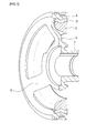
Fig. 1 is a sectional perspective showing the conventional structure of a damper pulley. It comprises of ahub 2 coupled with a crankshaft, apulley 4 and aspoke 6 extending radially between them. Arubber layer 8 is disposed underneath thepulley 4, and aweight 9 is attached under therubber layer 8 on the opposite side from thepulley 4. Thehub 2, thepulley 4 and thespoke 6 of the conventional damper pulley are made of cast iron integrally so as to have sufficient strength and durability, and theweight 9 is attached to thepulley 4 through theelastic rubber layer 8 to implement the damping action against vibration. - According to the tendency of demanding for weight reduction of car, the light weight engine and damper pulley is also demanded. But the conventional cast iron damper pulley, though having sufficient strength and durability, has a problem of heavy weight. If we make the depth of the
spoke 6 thinner in order to reduce the weight, the foaming formed on the surface the cast iron product causes the reduced effective section area, which results in the insufficient strength. Therefore, making of thin spoke could not be satisfactory solution. - Meanwhile, for the purpose of reducing the weight of damper pulley, a plastic hub and a steel hub of the damper pulley have been introduced. But these types of damper pulley do not have sufficient strength or durability to accommodate the severe vibration or torque. And in order to compensate the insufficient strength and durability, a rather complicated reinforcing elements should be added, which will result in the complicated structure, cumbersome manufacturing process and increased cost.
- The present invention is made to solve the above problem about the demand of reducing car weight and damper pulley, and the object of the invention is to provide a new lightweight damper pulley to be mountable on the crankshaft of engine and to be manufactured easily with desirable rigidity and durability.
- To achieve the above object, there is provided a damper pulley which comprises of a
cylindrical hub 12 being made of cast iron and coupled to the crankshaft of the engine, ahub plate 16 being made of steel plate and having acentral hole 22 on which thehub 12 is attached and arim 24 at the periphery of it, arubber layer 18 being attached on therim 24 of thehub plate 16, and a pulley attached on the outer surface of therubber layer 18. - Preferably but not necessarily, the
hub 12 is made of a ductile cast iron, and thehub plate 16 is formed with a cold rolled steel plate and welded to thehub 12 by brazing. - Preferably but not necessarily, the
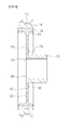
hub 12 includes aflange 26 extending outward at the attaching portion with thehub plate 16, and astep 28 projecting outward from the base of theflange 26, and thecentral hole 22 of thehub plate 16 being inserted on thestep 28 while thehub plate 16 tightly contacting theflange 26, and the hub plate 16being welded by brazing with thehub 12 at the end of theflange 26. -
-
FIG. 1 is a sectioned perspective of the conventional damper pulley. -
FIG. 2 is a section of the embodiment of the invention. -
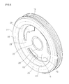
FIG. 3 is a perspective of the embodiment viewed from one side -
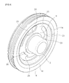
FIG. 4 is a perspective of the embodiment viewed from the other side. - Referring to
FIG. 2 to 4 , the preferred embodiment of the invention is explained. As shown inFig. 2 to 4 , the invention includes acylindrical hub 12 being coupled to the crankshaft of engine, ahub plate 16 attached to the periphery of thehub 12 and having acentral hole 22 andperipheral rim 24, arubber layer 18 being attached on the outer surface of therim 24 of thehub plate 16, and the pulley attached on the outer surface of therubber layer 18. - The
hub 12 of the invention is formed of a cast iron, preferably a ductile cast iron such as PCD450 with high strength, high wear resistance, high anti-corrosion and high impact resistance, and is finished by cutting or grinding. Thehub 12 includes anoutward flange 26 at the attaching area with thehub plate 16, and ashort step 28 is formed at the base of theflange 26. - The
hub plate 16 attached to thehub 12 is made of a steel plate, preferably SP steel such as SPCC through the press forming. Thehub plate 16 includes acentral hole 22 and arim 24 with T shape. Therim 24 could be formed by repetitive roll forming of the cold rolled steel plate to widen the width of the steel and deform the sectional shape of it progressively. Thehub plate 16 has theplural openings 23 outside thecentral hole 22 and theradial spokes 25 formed between theopenings 23. Astep 29 is formed at the inner edge of the opening 23. A tool may be engaged with thestep 29 to assemble or disassemble the damper pulley against the engine for the purpose of maintenance. - In order to firmly attach the
cylindrical hub 12 made of airon cast hub 12 and thehub plate 16 made of a cold rolled steel plate, both of them is welded by use of the brazing method. To do this, the projectingstep 28 of thehub 12 is forcedly fitted into thecentral hole 22 of thehub plate 16, and a filler metal such as ring shape brass is inserted at the contact portion between theflange 26 of thehub 12 and thehub plate 16, and heating them at the temperature above 1000°C, then the filler metal is melted into the gap between thehub 12 and thehub plate 16 to achieve firm and integral attachment. - The
rubber layer 16 of ring shape is attached on the outer surface of therim 24 at the periphery of thehub plate 15 to implement the damping action. Thepulley 14 is attached at the outer surface of therubber layer 18 to function as a weight for the damping action and the timing belts are hung on the pulley. Preferably the pulley is formed of cast iron and finished to have the grooves in which the belts are hung. - According to the invention, the
damper pulley 12 coupled to the crankshaft of the engine is made of a cast iron with high strength and durability, preferably the ductile cast iron with high wear resistance and high impact resistance, and thehub plate 16 attached to thehub 12 is made of a steel plate with relatively lighter than the cast iron and with easy forming property, and the different two materials are welded firmly by the brazing method, to meet the demand of the weight reduction of car and show the sufficient strength and durability against the periodically variable severe torque load, and achieve high wear resistance and impact resistance, as a result, to implement an excellent damping action of the damper pulley.
Claims (3)
- A damper pulley which comprises of a cylindrical hub 12 being made of cast iron and coupled to the crankshaft of the engine, a hub plate 16 being made of steel plate and having a central hole 22 on which the hub 12 is attached and a rim 24 at the periphery of it, a rubber layer 18 being attached on the rim 24 of the hub plate 16, and a pulley attached on the outer surface of the rubber layer 18.
- A damper pulley of claim 1, wherein the hub 12 is made of a ductile cast iron, and the hub plate 16 is formed with a cold rolled steel plate and welded to the hub 12 by brazing.
- A damper pulley of claim 1 or 2, wherein, the hub 12 includes a flange 26 extending outward at the attaching portion with the hub plate 16, and a step 28 projecting outward from the base of the flange 26, and the central hole 22 of the hub plate 16 being inserted on the step 28 while the hub plate 16 tightly contacting the flange 26, and the hub plate 16being welded by brazing with the hub 12 at the end of the flange 26.
Applications Claiming Priority (1)
| Application Number | Priority Date | Filing Date | Title |
|---|---|---|---|
| KR1020110020753A KR20120102879A (en) | 2011-03-09 | 2011-03-09 | Damper pulley |
Publications (1)
| Publication Number | Publication Date |
|---|---|
| EP2497971A2 true EP2497971A2 (en) | 2012-09-12 |
Family
ID=45444554
Family Applications (1)
| Application Number | Title | Priority Date | Filing Date |
|---|---|---|---|
| EP12150554A Withdrawn EP2497971A2 (en) | 2011-03-09 | 2012-01-10 | Lightweight damper pulley |
Country Status (4)
| Country | Link |
|---|---|
| US (1) | US20120231909A1 (en) |
| EP (1) | EP2497971A2 (en) |
| KR (1) | KR20120102879A (en) |
| CN (1) | CN102678884A (en) |
Cited By (2)
| Publication number | Priority date | Publication date | Assignee | Title |
|---|---|---|---|---|
| DE102015203302A1 (en) * | 2015-02-24 | 2016-08-25 | Bayerische Motoren Werke Aktiengesellschaft | Drive element for a high-pressure pump |
| EP3155293A4 (en) * | 2014-06-12 | 2018-03-07 | Dayco IP Holdings, LLC | Torsional vibration damper |
Families Citing this family (24)
| Publication number | Priority date | Publication date | Assignee | Title |
|---|---|---|---|---|
| DE112013002184T5 (en) * | 2012-04-24 | 2014-12-31 | Gkn Sinter Metals, Llc. | Damping device and corresponding method for producing the same |
| CN104334928B (en) * | 2012-05-08 | 2017-05-24 | 翰昂汽车零部件有限公司 | Compressor pulley assembly and method for manufacturing same |
| US9273773B2 (en) * | 2013-03-15 | 2016-03-01 | Magna Powertrain, Inc. | One-piece inertia ring and method of manufacturing the one-piece inertia ring |
| KR102010774B1 (en) * | 2013-07-10 | 2019-08-14 | 한온시스템 주식회사 | Power transmit device of clutchless compressor |
| ITRM20130672A1 (en) * | 2013-12-05 | 2015-06-06 | Ognibene Spa | SILENCED GEAR FOR TRANSMISSION CHAINS, IN PARTICULAR FOR MOTORCYCLES, AND MOLD COMPONENTS FOR ITS PRODUCTION. |
| US9581233B2 (en) | 2014-06-09 | 2017-02-28 | Dayco Ip Holdings, Llc | Torsional vibration damper with an interlocked isolator |
| US10030757B2 (en) * | 2014-07-01 | 2018-07-24 | Dayco Ip Holdings, Llc | Torsional vibration damper with an interlocked isolator |
| WO2016014531A1 (en) * | 2014-07-25 | 2016-01-28 | Dayco Ip Holdings, Llc | Low frequency torsional vibration damper |
| EP3175140B1 (en) * | 2014-08-01 | 2019-07-17 | Dayco IP Holdings, LLC | A two-part hub for a torsional vibration damper and method of making same |
| KR20170048389A (en) | 2014-09-02 | 2017-05-08 | 데이코 아이피 홀딩스 엘엘시 | Torsional vibration dampers having dual elastomeric members |
| US9945439B2 (en) * | 2015-01-16 | 2018-04-17 | Dayco Ip Holdings, Llc | Elastomer strip design for torsional vibration dampers and torsional vibration dampers having same |
| US9982747B2 (en) | 2015-04-22 | 2018-05-29 | Ford Global Technologies, Llc | Damper hub assembly and method of forming the same |
| KR101939391B1 (en) | 2017-04-20 | 2019-01-17 | 주식회사 피엔디티 | Damper pulley of heterogeneous material |
| CN106989158B (en) * | 2017-05-24 | 2023-07-14 | 宁波金鑫粉末冶金有限公司 | Driving wheel structure of automobile engine water pump |
| JP6811702B2 (en) * | 2017-12-19 | 2021-01-13 | Nok株式会社 | Tortional damper |
| WO2020051694A1 (en) * | 2018-09-10 | 2020-03-19 | Litens Automotive Partnership | Combined isolation and torsional vibration damping device |
| DE102018128641B4 (en) * | 2018-11-15 | 2024-03-28 | Schaeffler Technologies AG & Co. KG | Pulley decoupler with a toothing, auxiliary drive and drive motor with a corresponding pulley decoupler and method for producing a corresponding pulley decoupler |
| EP4080086A4 (en) * | 2019-12-20 | 2024-01-24 | NOK Corporation | Torsional damper |
| DE102020127092A1 (en) * | 2020-09-08 | 2022-03-10 | Schaeffler Technologies AG & Co. KG | Pulley decoupler with a support plate of a vibration absorber connected to a hub component |
| DE102021104889A1 (en) * | 2020-11-30 | 2022-06-02 | Schaeffler Technologies AG & Co. KG | drive wheel |
| KR102314262B1 (en) | 2021-04-30 | 2021-10-19 | 주식회사 신도 | Manufacturing method of damper pulley with improved productivity |
| CN113847397A (en) * | 2021-08-25 | 2021-12-28 | 一拖(洛阳)柴油机有限公司 | Belt secondary transmission device of diesel engine |
| KR20230075284A (en) | 2021-11-22 | 2023-05-31 | 김종목 | Machining tool of damper pulley using adhesive polymer material |
| US12372148B2 (en) * | 2022-01-07 | 2025-07-29 | Nok Corporation | Torsional damper |
Family Cites Families (8)
| Publication number | Priority date | Publication date | Assignee | Title |
|---|---|---|---|---|
| GB2233424B (en) * | 1989-06-29 | 1993-04-14 | Freudenberg Carl | Torsional vibration damper |
| DE4313755C1 (en) * | 1993-04-27 | 1994-06-23 | Freudenberg Carl Fa | Pulley |
| JP2000009209A (en) * | 1998-06-24 | 2000-01-11 | Bridgestone Corp | Damper pulley |
| US6386065B1 (en) * | 2000-07-25 | 2002-05-14 | The Gates Corporation | Dual ring damper |
| KR100435752B1 (en) * | 2001-12-07 | 2004-06-10 | 현대자동차주식회사 | A torsional crank shaft damper pulley of engine |
| JP4260528B2 (en) * | 2002-05-31 | 2009-04-30 | 株式会社フコク | Torsional damper pulley |
| US7047644B2 (en) * | 2003-02-21 | 2006-05-23 | The Gates Corporation | Crankshaft damper and method of assembly |
| CN201215170Y (en) * | 2008-07-15 | 2009-04-01 | 成都市西菱汽车配件有限责任公司 | Crankshaft vibration damping belt pulley |
-
2011
- 2011-03-09 KR KR1020110020753A patent/KR20120102879A/en not_active Ceased
- 2011-06-23 CN CN2011101734422A patent/CN102678884A/en active Pending
-
2012
- 2012-01-09 US US13/345,830 patent/US20120231909A1/en not_active Abandoned
- 2012-01-10 EP EP12150554A patent/EP2497971A2/en not_active Withdrawn
Non-Patent Citations (1)
| Title |
|---|
| None |
Cited By (2)
| Publication number | Priority date | Publication date | Assignee | Title |
|---|---|---|---|---|
| EP3155293A4 (en) * | 2014-06-12 | 2018-03-07 | Dayco IP Holdings, LLC | Torsional vibration damper |
| DE102015203302A1 (en) * | 2015-02-24 | 2016-08-25 | Bayerische Motoren Werke Aktiengesellschaft | Drive element for a high-pressure pump |
Also Published As
| Publication number | Publication date |
|---|---|
| US20120231909A1 (en) | 2012-09-13 |
| KR20120102879A (en) | 2012-09-19 |
| CN102678884A (en) | 2012-09-19 |
Similar Documents
| Publication | Publication Date | Title |
|---|---|---|
| EP2497971A2 (en) | Lightweight damper pulley | |
| KR102347563B1 (en) | Torsional vibration dampers | |
| EP1721821B1 (en) | Bicycle chainring | |
| US7481729B2 (en) | Lightweight sprocket | |
| US9371866B2 (en) | Wet clutch for a motorcycle | |
| US9644731B2 (en) | One-piece inertia ring for a harmonic damper | |
| KR20130039487A (en) | Torsional vibration damper | |
| MX2007015953A (en) | Sprocket. | |
| US9481205B2 (en) | Vehicle wheel | |
| WO2017035515A1 (en) | Torsional vibration dampers having a hub with spokes acting as a second spring in series with an elastomeric member | |
| PL202780B1 (en) | Crankshaft damper with integral pulse ring and method for production | |
| US20170234419A1 (en) | Torsional vibration dampers | |
| KR20160038483A (en) | Alternator damper pulley for vehicle | |
| KR100742027B1 (en) | Axle coupling structure of brake disc with integrated hub | |
| CA2636389A1 (en) | Wheel hub comprising axial recesses formed between the holes for wheel nuts | |
| KR102213987B1 (en) | A two-part hub for a torsional vibration damper and method of making same | |
| US20060293137A1 (en) | Pulley hub | |
| JP2013108578A (en) | Torsional damper | |
| US20070074942A1 (en) | Hydrodynamic torque converter | |
| US20170232792A1 (en) | Wheel securing structure of trucks | |
| JP2012177416A (en) | Wheel balance weight | |
| WO2024137448A1 (en) | Stacked sprocket and pulley | |
| JP4731430B2 (en) | Torsional damper and manufacturing method thereof | |
| CN102305257A (en) | Automobile leaf spring bush | |
| KR20130097474A (en) | A wheel |
Legal Events
| Date | Code | Title | Description |
|---|---|---|---|
| PUAI | Public reference made under article 153(3) epc to a published international application that has entered the european phase |
Free format text: ORIGINAL CODE: 0009012 |
|
| AK | Designated contracting states |
Kind code of ref document: A2 Designated state(s): AL AT BE BG CH CY CZ DE DK EE ES FI FR GB GR HR HU IE IS IT LI LT LU LV MC MK MT NL NO PL PT RO RS SE SI SK SM TR |
|
| AX | Request for extension of the european patent |
Extension state: BA ME |
|
| STAA | Information on the status of an ep patent application or granted ep patent |
Free format text: STATUS: THE APPLICATION IS DEEMED TO BE WITHDRAWN |
|
| 18D | Application deemed to be withdrawn |
Effective date: 20140801 |