EP2497924A2 - System and method for transitioning between fuel supplies for a combustion system - Google Patents
System and method for transitioning between fuel supplies for a combustion system Download PDFInfo
- Publication number
- EP2497924A2 EP2497924A2 EP12157991A EP12157991A EP2497924A2 EP 2497924 A2 EP2497924 A2 EP 2497924A2 EP 12157991 A EP12157991 A EP 12157991A EP 12157991 A EP12157991 A EP 12157991A EP 2497924 A2 EP2497924 A2 EP 2497924A2
- Authority
- EP
- European Patent Office
- Prior art keywords
- fuel
- purge
- valve
- gas
- closing
- Prior art date
- Legal status (The legal status is an assumption and is not a legal conclusion. Google has not performed a legal analysis and makes no representation as to the accuracy of the status listed.)
- Withdrawn
Links
- 239000000446 fuel Substances 0.000 title claims abstract description 529
- 238000002485 combustion reaction Methods 0.000 title claims description 66
- 238000000034 method Methods 0.000 title claims description 16
- 238000010926 purge Methods 0.000 claims abstract description 196
- 230000007704 transition Effects 0.000 claims description 28
- 230000000977 initiatory effect Effects 0.000 claims description 8
- 239000007789 gas Substances 0.000 description 117
- 238000007726 management method Methods 0.000 description 22
- 239000007788 liquid Substances 0.000 description 17
- 238000013021 overheating Methods 0.000 description 14
- 239000000047 product Substances 0.000 description 14
- 238000002347 injection Methods 0.000 description 10
- 239000007924 injection Substances 0.000 description 10
- 238000010790 dilution Methods 0.000 description 7
- 239000012895 dilution Substances 0.000 description 7
- XKRFYHLGVUSROY-UHFFFAOYSA-N Argon Chemical compound [Ar] XKRFYHLGVUSROY-UHFFFAOYSA-N 0.000 description 6
- IJGRMHOSHXDMSA-UHFFFAOYSA-N Atomic nitrogen Chemical compound N#N IJGRMHOSHXDMSA-UHFFFAOYSA-N 0.000 description 6
- CURLTUGMZLYLDI-UHFFFAOYSA-N Carbon dioxide Chemical compound O=C=O CURLTUGMZLYLDI-UHFFFAOYSA-N 0.000 description 6
- 238000010586 diagram Methods 0.000 description 6
- 239000000203 mixture Substances 0.000 description 6
- 238000004519 manufacturing process Methods 0.000 description 5
- 238000011144 upstream manufacturing Methods 0.000 description 4
- 229910052786 argon Inorganic materials 0.000 description 3
- 239000001569 carbon dioxide Substances 0.000 description 3
- 229910002092 carbon dioxide Inorganic materials 0.000 description 3
- 239000001307 helium Substances 0.000 description 3
- 229910052734 helium Inorganic materials 0.000 description 3
- SWQJXJOGLNCZEY-UHFFFAOYSA-N helium atom Chemical compound [He] SWQJXJOGLNCZEY-UHFFFAOYSA-N 0.000 description 3
- VNWKTOKETHGBQD-UHFFFAOYSA-N methane Chemical compound C VNWKTOKETHGBQD-UHFFFAOYSA-N 0.000 description 3
- 229910052757 nitrogen Inorganic materials 0.000 description 3
- 238000012546 transfer Methods 0.000 description 3
- UFHFLCQGNIYNRP-UHFFFAOYSA-N Hydrogen Chemical compound [H][H] UFHFLCQGNIYNRP-UHFFFAOYSA-N 0.000 description 2
- 230000002596 correlated effect Effects 0.000 description 2
- 230000007423 decrease Effects 0.000 description 2
- 230000003247 decreasing effect Effects 0.000 description 2
- 238000013461 design Methods 0.000 description 2
- 238000011161 development Methods 0.000 description 2
- 239000002737 fuel gas Substances 0.000 description 2
- UGFAIRIUMAVXCW-UHFFFAOYSA-N Carbon monoxide Chemical compound [O+]#[C-] UGFAIRIUMAVXCW-UHFFFAOYSA-N 0.000 description 1
- 230000000903 blocking effect Effects 0.000 description 1
- 239000006227 byproduct Substances 0.000 description 1
- 239000000571 coke Substances 0.000 description 1
- 239000000567 combustion gas Substances 0.000 description 1
- 230000001419 dependent effect Effects 0.000 description 1
- 230000000694 effects Effects 0.000 description 1
- 239000003546 flue gas Substances 0.000 description 1
- 239000001257 hydrogen Substances 0.000 description 1
- 229910052739 hydrogen Inorganic materials 0.000 description 1
- 238000012544 monitoring process Methods 0.000 description 1
- 239000003345 natural gas Substances 0.000 description 1
- 239000003921 oil Substances 0.000 description 1
- 238000012163 sequencing technique Methods 0.000 description 1
- 239000013589 supplement Substances 0.000 description 1
- 230000001502 supplementing effect Effects 0.000 description 1
Images



Classifications
-
- F—MECHANICAL ENGINEERING; LIGHTING; HEATING; WEAPONS; BLASTING
- F02—COMBUSTION ENGINES; HOT-GAS OR COMBUSTION-PRODUCT ENGINE PLANTS
- F02C—GAS-TURBINE PLANTS; AIR INTAKES FOR JET-PROPULSION PLANTS; CONTROLLING FUEL SUPPLY IN AIR-BREATHING JET-PROPULSION PLANTS
- F02C9/00—Controlling gas-turbine plants; Controlling fuel supply in air- breathing jet-propulsion plants
- F02C9/26—Control of fuel supply
- F02C9/40—Control of fuel supply specially adapted to the use of a special fuel or a plurality of fuels
-
- F—MECHANICAL ENGINEERING; LIGHTING; HEATING; WEAPONS; BLASTING
- F02—COMBUSTION ENGINES; HOT-GAS OR COMBUSTION-PRODUCT ENGINE PLANTS
- F02C—GAS-TURBINE PLANTS; AIR INTAKES FOR JET-PROPULSION PLANTS; CONTROLLING FUEL SUPPLY IN AIR-BREATHING JET-PROPULSION PLANTS
- F02C7/00—Features, components parts, details or accessories, not provided for in, or of interest apart form groups F02C1/00 - F02C6/00; Air intakes for jet-propulsion plants
- F02C7/22—Fuel supply systems
- F02C7/232—Fuel valves; Draining valves or systems
-
- F—MECHANICAL ENGINEERING; LIGHTING; HEATING; WEAPONS; BLASTING
- F05—INDEXING SCHEMES RELATING TO ENGINES OR PUMPS IN VARIOUS SUBCLASSES OF CLASSES F01-F04
- F05D—INDEXING SCHEME FOR ASPECTS RELATING TO NON-POSITIVE-DISPLACEMENT MACHINES OR ENGINES, GAS-TURBINES OR JET-PROPULSION PLANTS
- F05D2260/00—Function
- F05D2260/60—Fluid transfer
-
- F—MECHANICAL ENGINEERING; LIGHTING; HEATING; WEAPONS; BLASTING
- F05—INDEXING SCHEMES RELATING TO ENGINES OR PUMPS IN VARIOUS SUBCLASSES OF CLASSES F01-F04
- F05D—INDEXING SCHEME FOR ASPECTS RELATING TO NON-POSITIVE-DISPLACEMENT MACHINES OR ENGINES, GAS-TURBINES OR JET-PROPULSION PLANTS
- F05D2260/00—Function
- F05D2260/60—Fluid transfer
- F05D2260/602—Drainage
Definitions
- the subject matter disclosed herein relates to combustion systems with multi-fuel systems.
- gas turbine engines combust a mixture of compressed air and fuel to produce hot combustion gases.
- Certain gas turbine engines include multi-fuel systems that use, for example, both gas and liquid fuels, where the multi-fuel system allows the transfer from one fuel to the other.
- the multi-fuel system allows the transfer from one fuel to the other.
- use of the current fuel is terminated and the current fuel is discarded from the fuel piping system.
- Discarding the fuel occurs using a purge system that employs gas to displace the current fuel in the fuel piping system.
- certain sequencing of the termination of the current fuel used and the use of the purge system may result in overheating and backflow of combustion products into the fuel piping system resulting in hardware damage.
- the invention resides in a system including fuel controller.
- the fuel controller includes a purge control logic configured to control a purge sequence of mixing a purge gas with a first fuel during a first fuel shutdown or a fuel transition wherein the purge sequence is configured to open a purge valve for the purge gas before fully closing a fuel valve for the first fuel.
- the fuel controller may include a fuel transition logic configured to control a fuel transition from a first fuel to a second fuel for a combustion system.
- the invention resides in a method including transitioning a combustion system from a first fuel to a second fuel.
- the method also includes mixing a purge gas with the first fuel during the transitioning, wherein mixing includes opening a purge valve for the purge gas before fully closing a fuel valve for the first fuel.
- the present disclosure is directed to systems and methods for transitioning between fuel supplies for a combustion system (e.g., a gas turbine engine, combustion engine, gas-fired boiler, or furnace) with a multi-fuel system.
- a combustion system e.g., a gas turbine engine, combustion engine, gas-fired boiler, or furnace
- one fuel e.g., gas fuel
- another fuel e.g., liquid fuel
- Embodiments of the present disclosure provide a system that includes a fuel controller (e.g., turbine fuel controller) configured to control a fuel transition from the first fuel to the second fuel for the combustion system.
- the fuel controller includes logic (e.g., stored instructions stored on a non-transitory tangible computer readable medium) to transition between the first fuel (e.g., gas fuel) and the second fuel (e.g., liquid fuel).
- the fuel controller may include a fuel transition logic configured control the fuel transition from the first fuel to the second fuel.
- the fuel controller may include a purge control logic configured to control a purge sequence of mixing purge gas with the first fuel during the shutdown of the first fuel.
- the purge sequence may be configured to open a purge valve for the purge gas before fully closing a fuel valve for the first fuel.
- These systems are designed to allow for simultaneous termination and purging of the first fuel supply to avoid overheating within the combustion system by reducing the amount of unexpected fuel added to the combustion system after closure of the first fuel valve and to avoid backflow of combustion products into the fuel piping system by continuously maintaining a forward flow state.
- FIG. 1 is a schematic block diagram of an embodiment of a fuel management system 10 for a combustion system 12.
- the disclosed fuel management system 10 employs a fuel controller 14 (e.g., turbine fuel controller) to control the supply of fuel to the combustion system 12 (e.g., turbine engine or gas-fired boiler), in particular, the termination of one fuel supply and the transition to another fuel supply.
- the combustion system 12 may use multiple fuels, such as liquid and/or gas fuels, to feed the combustion system 12.
- a fuel injection system 16 intakes a fuel supply (e.g., liquid and/or gas fuel), mixes the fuel with air, and distributes the air-fuel mixture into the combustion system 12 in a suitable ratio for optimal combustion, emissions, fuel consumption, and power output.
- a fuel supply e.g., liquid and/or gas fuel
- the fuel management system 10 provides a flow of both a first fuel 18 and a second fuel 20 to the combustion system 12 via a first fuel line 22 and a second fuel line 24.
- each fuel 18 and 20 includes a single fuel line 22 and 24 to the fuel injection system 16; however, in other embodiments, each fuel 18 and 20 may include multiple fuel lines (e.g., 2 to 28) to the fuel injection system 16.
- the first fuel 18 includes a gas fuel and the second fuel 20 includes a liquid fuel.
- the first and second fuels 18 and 20 may be different gas fuels.
- Liquid fuel may include distillate oils, light crude, bio-liquid fuels, and other liquid fuels.
- Gas fuel may include natural gas and/or combustible gas(es) created as a byproduct of industrial processes which may or may not contain hydrogen gas. These combustible gases may be referred to as and include syngas, synthetic gas, synthetic natural gas, refinery off-gas, refinery flue gas, blast furnace gas, coke oven gas, or other combustible gases.
- Each fuel line 22 and 24 includes a respective valve 26 and 28 (e.g., fuel valves) configured to control the flow of the first and second fuels 18 and 20, respectively, to the fuel injection system 16.
- the fuel management system 10 includes a purge system 30 (e.g., dilution purge system) configured to purge the first fuel 18 from the first fuel line 22 and the fuel injection system 16 during termination of the first fuel flow.
- the purge system 30 includes a purge gas line 32 coupled to the first fuel line 22 downstream of the fuel valve 26 and upstream of the fuel injection system 16.
- the purge gas line 32 includes a valve 34 (e.g., purge valve) configured to control the flow of a purge gas 36 through the purge gas line 32 into the first fuel line 22 to purge the first fuel 18 from the fuel line 22 and the fuel injection system 16.
- the purge gas 36 may include an inert purge gas 36.
- an inert purge gas 36 may be used when the first fuel 18 has a low auto ignition temperature (e.g., fuels containing more than 5 percent hydrogen by volume) to prevent auto ignition of the fuel/purge gas mixture.
- the inert purge gas 36 may also be used with other types of gaseous fuels.
- the inert purge gas 36 may include nitrogen, carbon dioxide, argon, or helium, or in certain cases, steam.
- the purge system 30, as described may also be configured to control the flow of purge gas 36 into the second fuel line 24 to purge the second fuel 20 from the fuel line 24 and the fuel injection system 16.
- the combustion system 12 operates on the first fuel 18 (e.g., gas fuel) as the primary fuel, and selectively operates on the second fuel 20 (e.g., liquid fuel) as a secondary fuel.
- the logic may be disposed on a non-transitory tangible computer readable medium.
- the fuel controller 14 is configured to control a supply of the first fuel (e.g., gas fuel) to the combustion system 12, a supply of the second fuel (e.g., liquid fuel) to the combustion system 12, and the transition between the use of the first and second fuels 18 and 20 for the combustion system 12.
- the fuel controller 14 is coupled to the fuel valves 26 and 28 for the first and second fuels 18 and 20, respectively, and the purge valve 34.
- the fuel controller 14 is configured to open and close valves 26, 28, and 38 to control the flow of the first fuel 18, second fuel 20, and purge gas 36.
- the purge gas 36 with the first fuel 18 during the first fuel shutdown, as opposed to after the shutdown, prevents the unscheduled addition of the first fuel 18 from the fuel line 22 to the combustion system 12 subsequent to the first fuel shutdown, as is currently the common practice, thus, preventing overheating of the system 12.
- the dilution purge maintains some flow through the fuel injection system 16 to prevent backflow of combustion products into the piping system (e.g., first fuel line 22) until an air purge is established to maintain the above mentioned backflow protection.
- the purge sequence is configured to open the purge valve 34 for the purge gas 36 before fully closing the fuel valve 26 for the first fuel 18.
- the purge sequence is configured to start opening the purge valve 34 after starting to close the fuel valve 26.
- the purge sequence is configured to start opening the purge valve 34 after a specific percent closure of the fuel valve 26 ranging from approximately 60 to 90 percent closure of the valve 26.
- the start of the opening of the purge valve 34 may occur at approximately 60, 70, 80, or 90 percent closure of the fuel valve 26, or any other percent therebetween.
- the start of the opening the purge valve 34 may be based on the first fuel flow reaching a predetermined percentage of the total fuel required by the combustion system 12.
- the rate of the opening the purge valve 34 may be dependent on conditions in the combustion system 12.
- the purge sequence may be configured to increase a rate of opening of the purge valve 34 if a flame extinguishes in the combustion system 12 (e.g., gas turbine engine) to remove the backflow risk until making it acceptable to close the purge valve 34.
- the purge sequence includes a fuel valve closing duration of progressively closing the fuel valve 26 from an open position to a closed position, a purge valve opening duration of progressively opening the purge valve 34 from a closed position to an open position, and the fuel valve closing duration overlaps the purge valve opening duration.
- the purge valve opening duration completes before the fuel valve 26 reaches the closed position during the fuel valve closing duration.
- the purge valve opening duration starts after initiation of the fuel valve closing duration.
- the purge valve opening duration starts after a specific percent closure (e.g., 70 percent) closure of the fuel valve 26 during the fuel valve closing duration.
- the fuel management system 10 avoids overheating within the combustion system 12 by reducing the amount of unexpected fuel added to the combustion system 12 after closure of the first fuel valve 26 and backflow of combustion products into the fuel piping system by continuously maintaining a forward flow state.
- the combustion system 12 may include a turbine system 50 (e.g., gas turbine engine).
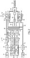
- FIG. 2 is a schematic block diagram of an embodiment of the fuel management system 10 for the turbine system 50, where the first fuel 18 is a gas fuel and the second fuel 20 is a gas fuel.
- the fuel management system 10 employs the fuel controller 14 (e.g., turbine fuel controller 14) to control the supply of fuel to the turbine system 50, in particular, the termination of one fuel supply and the transition to another fuel supply.
- the turbine system 50 may use multiple fuels, as described above (e.g., multiple gas fuels) as the heat source for the turbine system 50.
- one or more fuel nozzles 52 and 54 intake a fuel supply (e.g., gas fuel), mix the fuel with air, and distribute the air-fuel mixture into a combustor 58 (e.g., fuel combustor 60 and fuel combustor 62) in a suitable ratio for optimal combustion, emissions, fuel consumption, and power output.
- a fuel supply e.g., gas fuel
- each combustor 58 includes one or more primary fuel nozzles 52 and one or more secondary fuel nozzles 54.
- the air-fuel mixture combusts in a chamber within each combustor 58, thereby creating hot pressurized exhaust gases.
- Each combustor 58 directs the exhaust gases through a turbine 64 toward an exhaust outlet.
- the shaft 66 may be connected to various components of the turbine system 50, including a compressor 68.
- the compressor 68 also includes blades coupled to the shaft 66.
- the blades within the compressor 68 also rotate, thereby compressing air from an air intake through the compressor 68 and into the fuel nozzles 52 and 54 and/or combustors 58.
- the shaft 66 may also be connected to a load, such as an electrical generator 70 in an electrical power plant, for example.
- the load may include any suitable device capable of being powered by the rotational mechanical power output of the turbine system 50.
- the fuel management system 10 provides a flow of both the first fuel 18 (e.g., first gas fuel) and the second fuel 20 (e.g., second gas fuel) to the turbine system 50.
- each supply of fuel 18 and 20 includes a main fuel line 72 and 74, respectively.
- Each main fuel line 72 and 74 includes a respective valve 26 and 28 (e.g., fuel valves) configured to control the flow of the first and second fuels 18 and 20, respectively, to secondary fuel nozzles 54.
- the main fuel line 72 includes a flow splitter 76.
- the flow splitter 76 divides the first fuel flow into first fuel lines 80 and 82.
- the first fuel line 80 splits to divide the flow of first fuel between the primary fuel nozzles 52.
- the first fuel line 82 is coupled to the main fuel line 74 downstream of the valve 28, but upstream of where the main fuel line 86 splits to provide the first fuel 18, the second fuel 20, or a combination of both the first and second fuels 18 and 20 to the fuel nozzles 54.
- the first fuel line 80 provides first fuel 18 (e.g., first gas fuel) to primary fuel nozzles 52, while the main fuel lines 74 and 86 provide the first fuel 18, the second fuel 20, or a combination of both the first and second fuels 18 and 20 to the secondary fuel nozzles 54.
- the fuel management system 10 includes the purge system 30 (e.g., dilution purge system) configured to purge the first fuel 18 from the first fuel lines 80 and 82, the main fuel lines 74 and 86, and the fuel nozzles 52 and 54 during termination of the first fuel flow.
- the purge system 30 includes purge gas lines 88 and 90 coupled to respective first fuel lines 80 and 82 downstream of the flow splitter 76 and upstream of the fuel nozzles 52 and 54.
- Purge of lines 74, 82, 86, and 90 and secondary fuel nozzles 54 may not be required if the second fuel 20 has had sufficient time to displace the first fuel 18 in lines 74, 82, 86, and 90 and fuel nozzles 54 during a controlled transfer from the first fuel 18 or a combination of the first and second fuels 18 and 20 to the second fuel 20 only in lines 74, 82, 86, and 90 and fuel nozzles 54.
- the fuel management system 10 includes fuel controller 14 configured to control the supply of the first fuel 18 (e.g., first gas fuel) to the turbine system 50, the supply of the second fuel 20 (e.g., second gas fuel) to the turbine system 50, and the transition between the use of the first and second fuels 18 and 20 for the turbine system 50.
- the fuel controller 14 is coupled to the fuel valves 26 and 28 for the first and second fuels 18 and 20, respectively, and the purge valves 92 and 94.
- the fuel controller 14 is configured to open and close valves 26, 28, 92, and 94 to control the flow of the first fuel 18, second fuel 20, and the purge gas 36.
- the fuel controller 14 includes logic, as described above, (e.g., the fuel transition control logic 38 and the purge control logic 40) configured to control the transition from the first fuel 18 to the second fuel 20, as well as to control the purge sequence of mixing purge gas 36 with the first fuel 18 (i.e., dilution purge) during a first fuel shutdown or termination.
- the fuel controller 14 may employ the logic and control the purge system 30 for fuel lines 74, 80, 82, and 86 simultaneously or independently.
- the fuel management system 10 avoids overheating within the turbine system 50 by reducing the amount of unexpected fuel added to the turbine system 50 after closure of the first fuel valve 26 and backflow of combustion products into the fuel piping system by continuously maintaining a forward flow state.
- FIG. 3 is a schematic block diagram of an embodiment of the fuel management system 10 for the turbine system 50 where the first fuel 18 includes a gas fuel and the second fuel 20 includes a liquid fuel.
- the fuel management system 10 provides a flow of both the first fuel 18 (e.g., gas fuel) and the second fuel 20 (e.g., liquid fuel) to the turbine system 50.
- each supply of fuel 18 and 20 includes a main fuel line 72 and 74, respectively.
- Each main fuel line 72 and 74 includes a respective valve 26 and 28 (e.g., fuel valves) configured to control the flow of the first and second fuels 18 and 20, respectively, to fuel nozzles 52 and 54.
- the main fuel line 72 splits to divide the flow of the first fuel 18 to the fuel nozzles 52, while the main fuel line 74 splits to divide the flow of the second fuel 20 to the fuel nozzles 54.
- the number of fuel lines may vary (e.g., 2 to 28 fuel lines).
- the fuel management system 10 includes the purge system 30 (e.g., dilution purge system) configured to purge the first fuel 18 from the main fuel line 72 and the fuel nozzles 52 during termination of the first fuel flow.
- the purge system 30 includes purge gas line 88 coupled to the main fuel line 72 downstream of the valve 26 and upstream of the fuel nozzles 52 (and the split of the main fuel line 72).
- the purge gas line 88 includes valve 92 (e.g., purge valve) configured to control the flow of purge gas 36 (e.g., inert purge gas) through the line 88 into the fuel lines 72 and 80 to purge the first fuel 18 from the fuel lines 72 and 80 and the fuel nozzles 52.
- the inert purge gas 36 may include nitrogen, carbon dioxide, argon, or helium, or in certain cases, steam.
- the fuel management system 10 includes fuel controller 14 configured to control the supply of the first fuel 18 (e.g., gas fuel) to the turbine system 50, the supply of the second fuel 20 (e.g., liquid fuel) to the turbine system 50, and the transition between the use of the first and second fuels 18 and 20 for the turbine system 50.
- the fuel controller 14 is coupled to the fuel valves 26 and 28 for the first and second fuels 18 and 20, respectively, and the purge valve 92.
- the fuel controller 14 is configured to open and close valves 26, 28, and 92 to control the flow of the first fuel 18, second fuel 20, and the purge gas 36.
- the fuel controller 14 includes logic, as described above, (e.g., the fuel transition control logic 38 and the purge control logic 40) configured to control the transition from the first fuel 18 to the second fuel 20, as well as to control the purge sequence of mixing purge gas 36 with the first fuel 18 (i.e., dilution purge) during a first fuel shutdown or termination.
- the fuel management system 10 avoids overheating within the turbine system 50 by reducing the amount of unexpected fuel added to the turbine system 50 after closure of the first fuel valve 26 and backflow of combustion products into the fuel piping system by continuously maintaining a forward flow state.
- FIG. 4 is a graphical representation 104 of an embodiment of the purge sequence described above, illustrating an opening and closing of the first fuel valve 26 and the purge valve 34.
- the graph 104 includes a vertical axis 106 representing the valve position of the fuel valve 26 and the purge valve 34.
- a top 108 of the vertical axis 106 represents a fully opened valve position and a bottom 110 of the vertical axis 106 represents a fully closed valve position.
- the graph 104 also includes a horizontal axis 112 representing time. Time increases from left to right along the horizontal axis 112.
- the graph 104 includes a plot 114, illustrated by a solid line, representing the valve position of the first fuel valve 26 (e.g., gas fuel valve) and a plot 116, illustrated by a dashed line, representing the valve position of the purge valve 34.
- a plot 114 illustrated by a solid line
- a plot 116 illustrated by a dashed line
- the fuel valve closing duration may lasts approximately 15, 30, 45, 60, 75, 90, 105, 120, 135, 150, 175, or 180 seconds, or any time therebetween.
- the controller 14 initiates a purge valve opening duration, represented by region 132 of plot 116, of progressively opening the purge valve 36 from the closed position 122 to an open position 134.
- the purge valve opening duration 132 is shorter than the fuel valve closing duration 132, since the purge valve 34 may be smaller than the fuel valve 26.
- the purge valve opening duration 132 starts after initiation 124 of the fuel valve closing duration 126 and overlaps the fuel valve closing duration 126.
- the purge valve opening duration 132 completes (i.e., the purge valve 34 reaches a fully open position, represented by region 134 of the plot 116) during the fuel valve closing duration 126.
- the purge valve opening duration 132 may start after a certain percent closure (e.g., approximately 70 percent closure) of the fuel valve 26 during the fuel valve closing duration 126.
- the specific percent closure of the fuel valve 26 during the fuel valve closing duration to trigger the start of the purge valve opening duration may range from approximately 60 to 90 percent closure of the valve 26.
- the purge valve opening duration 132 may occur at approximately 60, 70, 80, or 90 percent closure of the fuel valve 26, or any other percent therebetween.
- FIG. 5 is a graphical representation 144 of an embodiment of a fuel flow (e.g., gas fuel flow) during the purge sequence described above.
- the graph 144 includes a vertical axis 146 representing fuel flow of first fuel 18 (e.g., gas fuel). Fuel flow increases from the bottom to the top along the vertical axis 146.
- the graph 144 also includes a horizontal axis 148 representing time. Time increases from left to right along the horizontal axis 148.
- Plot 154 illustrates the fuel flow decreasing during the fuel valve closing duration described above. Initiation of the opening of the purge valve 34, indicated by reference numeral 156, results in a small peak 158 in fuel flow at the combustion system 12. This occurs due to the purge gas 36 displacing the first fuel 18 (e.g., gas fuel) temporarily causing a greater fuel flow into the combustion system 12. While flow of the purge gas 36 increases and the fuel flow of the first fuel 18 gradually decreases, the first fuel valve 26 eventually fully closes as indicated by reference numeral 160. As illustrated, the closing 160 of the first fuel valve 26 does not cause a spike in the fuel flow rate that would result in an unexpected amount of first fuel 18 in the combustion system 12 and consequentially overheating within the engine.
- the closing 160 of the first fuel valve 26 does not cause a spike in the fuel flow rate that would result in an unexpected amount of first fuel 18 in the combustion system 12 and consequentially overheating within the engine.
- the fuel flow does not increase to a level to trigger the overtemperature alarm limit 150 and the overtemperature alarm limit 152.
- the fuel flow may spike, as indicated by peak 161 of plot 155, and trip the alarm limits 150 and 152 due to the unexpected addition of fuel to the combustion system 12 after closure of the valve 26.
- the purge sequence as described above avoids the delivery of unexpected fuel to the engine that may result in overheating and damage to equipment.
- FIG. 6 is a graphical representation 170 of an embodiment of a gas flow during the purge sequence described above.
- the graph 170 includes a vertical axis 172 representing gas flow (e.g., through a fuel nozzle) of the first fuel 18 and purge gas 36. Gas flow increases from the bottom to the top along the vertical axis 172.
- the graph 170 also includes a horizontal axis 174 representing time. Time increases from left to right along the horizontal axis 174.
- the graph 170 further includes a dashed line 176 representing the minimum gas flow rate to prevent back flow, for example, into the fuel nozzle and fuel piping system.
- the graph 170 also includes plot 177 representing the gas flow over time in the absence of the purge sequence.
- Plot 178 illustrates the gas flow decreasing during the fuel valve closing duration and the purge valve opening duration as described above.
- the gas flow Prior to initiation of the opening of the purge valve 34 as indicated by reference numeral 180, the gas flow consists entirely of the flow of the first fuel 18 (e.g., gas fuel). After opening 180 the purge valve 34, a small peak 182 in gas flow occurs due to the purge gas 36 supplementing the first fuel 18 temporarily causing a greater overall gas flow.
- the gas flow from the opening 180 of the purge valve 34 to the closing of the first fuel valve 26 e.g., gas fuel valve
- the gas flow gradually decreases until the closing 184 of the first fuel valve 26.
- the purge gas flow supplements the first fuel flow during the fuel valve closing duration to maintain the gas flow above the minimum gas flow rate, and then continues after the closing 184 of the first fuel valve 26.
- FIG. 7 is a sequence flow chart of an embodiment of a process 196 for purging the first fuel 18 (e.g., gas fuel) from the first fuel line.
- the process 196 employs the purge sequence described above to avoid overheating within the combustion system 12 and backflow of combustion products into the fuel piping system.
- the fuel controller 14, as described above, implements the process 196.
- the process 196 includes initiating a transition from the first fuel 18 (e.g., gas fuel) to the second fuel 20 (e.g., liquid fuel) (block 198). Indeed, the transition includes beginning the closing of the first fuel valve 26 (block 200).
- the controller 14 monitors the closing of the first fuel valve 26 by monitoring one or more parameters (block 202).
- the parameters monitored by the controller 14 include percent closure of the fuel valve 26, first fuel flow rate, temperature of the combustion system 12, and/or other parameters.
- the controller 14 may monitor one or more of these parameters. In particular, the controller 14 may inquire if the fuel valve closing is equal to or greater than a threshold percentage (e.g., approximately 70 percent) for closure of the fuel valve 26 (block 204).
- a threshold percentage e.g., approximately 70 percent
- the threshold percentage for closure of the fuel valve 26 may range from approximately 60 to 90 percent closure of the valve 26.
- the threshold percentage may be approximately 60, 70, 80, or 90 percent closure of the fuel valve 26, or any other percent therebetween. If the percent fuel valve closure remains below the threshold percentage, the controller 14 continues to monitor the closing of the first fuel valve 26 (block 202). However, if the percent fuel valve closure equals or surpasses the threshold percentage for closure of the fuel valve 26, then the controller 14 may also inquire if the fuel flow of the first fuel 18 falls below a desired threshold for the fuel flow (block 206). If the fuel flow remains above the fuel flow threshold, the controller 14 continues to monitor the closing of the first fuel valve (block 202). However, if the fuel flow equals or falls below the fuel flow threshold, the controller 14 begins opening the purge valve 34 to mix purge gas 36 with the first fuel 18 (block 208).
- the controller 14 gradually opens the purge valve 34 to a fully opened position (block 210).
- the rate of opening the purge valve may increase if a flame extinguishes (e.g., mechanical trip) in the combustion system 12 in order to maintain some gas flow into the system 12 and to avoid hardware damage.
- the controller 14 fully closes the fuel valve 26 for the first fuel 18.
- the process 196 enables the fuel management system 10 to avoid overheating within the combustion system 12 by reducing the amount of unexpected fuel added to the combustion system 12 after closure of the first fuel valve 26 and blocking backflow of combustion products into the fuel piping system by continuously maintaining a forward flow state.
- the disclosed embodiments may avoid overheating within the combustion system 12 by preventing unexpected first fuel flow into the system 12.
- the disclosed embodiments may avoid backflow of combustion products into the fuel piping by maintaining some forward flow through the piping. As a result, damage may be avoided to equipment due to the overheating or the backflow of combustion products.
Landscapes
- Engineering & Computer Science (AREA)
- Chemical & Material Sciences (AREA)
- Combustion & Propulsion (AREA)
- Mechanical Engineering (AREA)
- General Engineering & Computer Science (AREA)
- Feeding And Controlling Fuel (AREA)
Abstract
A system includes a turbine fuel controller (14). The turbine fuel controller (14) includes a purge control logic (40) configured to control a purge sequence of mixing an inert purge gas (36) with a first fuel (18) during a first fuel shutdown, wherein the purge sequence is configured to open a purge valve (34, 92, and 94) for the inert purge gas (36) before fully closing a fuel valve (26) for the first fuel (18).
Description
- The subject matter disclosed herein relates to combustion systems with multi-fuel systems.
- In general, gas turbine engines combust a mixture of compressed air and fuel to produce hot combustion gases. Certain gas turbine engines include multi-fuel systems that use, for example, both gas and liquid fuels, where the multi-fuel system allows the transfer from one fuel to the other. During the transfer from one fuel to another fuel, use of the current fuel is terminated and the current fuel is discarded from the fuel piping system. Discarding the fuel occurs using a purge system that employs gas to displace the current fuel in the fuel piping system. However, certain sequencing of the termination of the current fuel used and the use of the purge system may result in overheating and backflow of combustion products into the fuel piping system resulting in hardware damage.
- Certain embodiments commensurate in scope with the originally claimed invention are summarized below. These embodiments are not intended to limit the scope of the claimed invention, but rather these embodiments are intended only to provide a brief summary of possible forms of the invention. Indeed, the invention may encompass a variety of forms that may be similar to or different from the embodiments set forth below.
- In accordance with a first aspect, the invention resides in a system including fuel controller. The fuel controller includes a purge control logic configured to control a purge sequence of mixing a purge gas with a first fuel during a first fuel shutdown or a fuel transition wherein the purge sequence is configured to open a purge valve for the purge gas before fully closing a fuel valve for the first fuel.
- The fuel controller may include a fuel transition logic configured to control a fuel transition from a first fuel to a second fuel for a combustion system.
- In accordance with a second aspect, the invention resides in a method including transitioning a combustion system from a first fuel to a second fuel. The method also includes mixing a purge gas with the first fuel during the transitioning, wherein mixing includes opening a purge valve for the purge gas before fully closing a fuel valve for the first fuel.
- Embodiments of the present invention will now be described, by way of example only, with reference to the accompanying drawings in which:
-
FIG. 1 is a schematic block diagram of an embodiment of a fuel management system for a combustion system; -
FIG. 2 is a schematic block diagram of an embodiment of a fuel management system for a turbine system; -
FIG. 3 is a schematic block diagram of another embodiment of a fuel management system for a turbine system; -
FIG. 4 is a graphical representation of an embodiment of a purge sequence illustrating an opening and closing of a fuel valve and a purge valve; -
FIG. 5 is a graphical representation of an embodiment of a fuel flow during the purge sequence; -
FIG. 6 is a graphical representation of an embodiment of a gas flow during the purge sequence; and -
FIG. 7 is a flow chart of an embodiment of a process for purging a fuel from a fuel line. - One or more specific embodiments of the present invention will be described below. In an effort to provide a concise description of these embodiments, all features of an actual implementation may not be described in the specification. It should be appreciated that in the development of any such actual implementation, as in any engineering or design project, numerous implementation-specific decisions must be made to achieve the developers' specific goals, such as compliance with system-related and business-related constraints, which may vary from one implementation to another. Moreover, it should be appreciated that such a development effort might be complex and time consuming, but would nevertheless be a routine undertaking of design, fabrication, and manufacture for those of ordinary skill having the benefit of this disclosure.
- When introducing elements of various embodiments of the present invention, the articles "a," "an," "the," and "said" are intended to mean that there are one or more of the elements. The terms "comprising," "including," and "having" are intended to be inclusive and mean that there may be additional elements other than the listed elements.
- The present disclosure is directed to systems and methods for transitioning between fuel supplies for a combustion system (e.g., a gas turbine engine, combustion engine, gas-fired boiler, or furnace) with a multi-fuel system. In combustion systems with multi-fuel systems, one fuel (e.g., gas fuel) may be the primary fuel source used by the combustion system, while another fuel (e.g., liquid fuel) may be the secondary or backup fuel source for occasional use. Embodiments of the present disclosure provide a system that includes a fuel controller (e.g., turbine fuel controller) configured to control a fuel transition from the first fuel to the second fuel for the combustion system. The fuel controller includes logic (e.g., stored instructions stored on a non-transitory tangible computer readable medium) to transition between the first fuel (e.g., gas fuel) and the second fuel (e.g., liquid fuel). For example, the fuel controller may include a fuel transition logic configured control the fuel transition from the first fuel to the second fuel. Also, the fuel controller may include a purge control logic configured to control a purge sequence of mixing purge gas with the first fuel during the shutdown of the first fuel. In particular, the purge sequence may be configured to open a purge valve for the purge gas before fully closing a fuel valve for the first fuel. These systems are designed to allow for simultaneous termination and purging of the first fuel supply to avoid overheating within the combustion system by reducing the amount of unexpected fuel added to the combustion system after closure of the first fuel valve and to avoid backflow of combustion products into the fuel piping system by continuously maintaining a forward flow state.
-
FIG. 1 is a schematic block diagram of an embodiment of afuel management system 10 for acombustion system 12. As described in detail below, the disclosedfuel management system 10 employs a fuel controller 14 (e.g., turbine fuel controller) to control the supply of fuel to the combustion system 12 (e.g., turbine engine or gas-fired boiler), in particular, the termination of one fuel supply and the transition to another fuel supply. Thecombustion system 12 may use multiple fuels, such as liquid and/or gas fuels, to feed thecombustion system 12. As depicted in thecombustion system 12, afuel injection system 16 intakes a fuel supply (e.g., liquid and/or gas fuel), mixes the fuel with air, and distributes the air-fuel mixture into thecombustion system 12 in a suitable ratio for optimal combustion, emissions, fuel consumption, and power output. - The
fuel management system 10 provides a flow of both afirst fuel 18 and asecond fuel 20 to thecombustion system 12 via afirst fuel line 22 and asecond fuel line 24. As illustrated, eachfuel single fuel line fuel injection system 16; however, in other embodiments, eachfuel fuel injection system 16. In certain embodiments, thefirst fuel 18 includes a gas fuel and thesecond fuel 20 includes a liquid fuel. In other embodiments, the first andsecond fuels fuel line respective valve 26 and 28 (e.g., fuel valves) configured to control the flow of the first andsecond fuels fuel injection system 16. - As illustrated, the
fuel management system 10 includes a purge system 30 (e.g., dilution purge system) configured to purge thefirst fuel 18 from thefirst fuel line 22 and thefuel injection system 16 during termination of the first fuel flow. Thepurge system 30 includes apurge gas line 32 coupled to thefirst fuel line 22 downstream of thefuel valve 26 and upstream of thefuel injection system 16. Thepurge gas line 32 includes a valve 34 (e.g., purge valve) configured to control the flow of apurge gas 36 through thepurge gas line 32 into thefirst fuel line 22 to purge thefirst fuel 18 from thefuel line 22 and thefuel injection system 16. In certain embodiments, thepurge gas 36 may include aninert purge gas 36. For example, aninert purge gas 36 may be used when thefirst fuel 18 has a low auto ignition temperature (e.g., fuels containing more than 5 percent hydrogen by volume) to prevent auto ignition of the fuel/purge gas mixture. Theinert purge gas 36 may also be used with other types of gaseous fuels. Theinert purge gas 36 may include nitrogen, carbon dioxide, argon, or helium, or in certain cases, steam. In certain embodiments, when thesecond fuel 20 is a gaseous fuel, thepurge system 30, as described, may also be configured to control the flow ofpurge gas 36 into thesecond fuel line 24 to purge thesecond fuel 20 from thefuel line 24 and thefuel injection system 16. - In certain embodiments, the
combustion system 12 operates on the first fuel 18 (e.g., gas fuel) as the primary fuel, and selectively operates on the second fuel 20 (e.g., liquid fuel) as a secondary fuel. The logic may be disposed on a non-transitory tangible computer readable medium. Thefuel controller 14 is configured to control a supply of the first fuel (e.g., gas fuel) to thecombustion system 12, a supply of the second fuel (e.g., liquid fuel) to thecombustion system 12, and the transition between the use of the first andsecond fuels combustion system 12. Thefuel controller 14 is coupled to thefuel valves second fuels purge valve 34. In particular, thefuel controller 14 is configured to open andclose valves first fuel 18,second fuel 20, andpurge gas 36. - The
fuel controller 14 includes logic configured to manage the supply of thefuels combustion system 12. For example, thefuel controller 14 includes a fueltransition control logic 38 configured to control a fuel transition from thefirst fuel 18 to thesecond fuel 20 for the combustion system 12 (e.g., gas turbine engine). Thefuel controller 14 also includes apurge control logic 40 configured to control a purge sequence of mixing thepurge gas 36 with the first fuel 18 (i.e., dilution purge) during fuel transition, particularly, during first fuel shutdown or termination. Mixing thepurge gas 36 with thefirst fuel 18 during the first fuel shutdown, as opposed to after the shutdown, prevents the unscheduled addition of thefirst fuel 18 from thefuel line 22 to thecombustion system 12 subsequent to the first fuel shutdown, as is currently the common practice, thus, preventing overheating of thesystem 12. In addition, the dilution purge maintains some flow through thefuel injection system 16 to prevent backflow of combustion products into the piping system (e.g., first fuel line 22) until an air purge is established to maintain the above mentioned backflow protection. - In certain embodiments, the purge sequence is configured to open the
purge valve 34 for thepurge gas 36 before fully closing thefuel valve 26 for thefirst fuel 18. In particular, the purge sequence is configured to start opening thepurge valve 34 after starting to close thefuel valve 26. In some embodiments, the purge sequence is configured to start opening thepurge valve 34 after a specific percent closure of thefuel valve 26 ranging from approximately 60 to 90 percent closure of thevalve 26. For example, the start of the opening of thepurge valve 34 may occur at approximately 60, 70, 80, or 90 percent closure of thefuel valve 26, or any other percent therebetween. Alternatively, the start of the opening thepurge valve 34 may be based on the first fuel flow reaching a predetermined percentage of the total fuel required by thecombustion system 12. Also, the rate of the opening thepurge valve 34 may be dependent on conditions in thecombustion system 12. For example, the purge sequence may be configured to increase a rate of opening of thepurge valve 34 if a flame extinguishes in the combustion system 12 (e.g., gas turbine engine) to remove the backflow risk until making it acceptable to close thepurge valve 34. - In some embodiments, the purge sequence includes a fuel valve closing duration of progressively closing the
fuel valve 26 from an open position to a closed position, a purge valve opening duration of progressively opening thepurge valve 34 from a closed position to an open position, and the fuel valve closing duration overlaps the purge valve opening duration. In certain embodiments, the purge valve opening duration completes before thefuel valve 26 reaches the closed position during the fuel valve closing duration. As above, the purge valve opening duration starts after initiation of the fuel valve closing duration. Also, as above, the purge valve opening duration starts after a specific percent closure (e.g., 70 percent) closure of thefuel valve 26 during the fuel valve closing duration. As a result of this logic, thefuel management system 10 avoids overheating within thecombustion system 12 by reducing the amount of unexpected fuel added to thecombustion system 12 after closure of thefirst fuel valve 26 and backflow of combustion products into the fuel piping system by continuously maintaining a forward flow state. - As mentioned above, the
combustion system 12 may include a turbine system 50 (e.g., gas turbine engine).FIG. 2 is a schematic block diagram of an embodiment of thefuel management system 10 for theturbine system 50, where thefirst fuel 18 is a gas fuel and thesecond fuel 20 is a gas fuel. Similar to above, thefuel management system 10 employs the fuel controller 14 (e.g., turbine fuel controller 14) to control the supply of fuel to theturbine system 50, in particular, the termination of one fuel supply and the transition to another fuel supply. Also, theturbine system 50 may use multiple fuels, as described above (e.g., multiple gas fuels) as the heat source for theturbine system 50. As depicted in theturbine system 50, one ormore fuel nozzles 52 and 54 (e.g.,primary fuel nozzle 52 and secondary fuel nozzle 54) intake a fuel supply (e.g., gas fuel), mix the fuel with air, and distribute the air-fuel mixture into a combustor 58 (e.g.,fuel combustor 60 and fuel combustor 62) in a suitable ratio for optimal combustion, emissions, fuel consumption, and power output. In certain embodiments, each combustor 58 includes one or moreprimary fuel nozzles 52 and one or moresecondary fuel nozzles 54. The air-fuel mixture combusts in a chamber within eachcombustor 58, thereby creating hot pressurized exhaust gases. Eachcombustor 58 directs the exhaust gases through aturbine 64 toward an exhaust outlet. - As the exhaust gases pass through the
turbine 64, the gases force turbine blades to rotate ashaft 66 along an axis of theturbine system 50. As illustrated, theshaft 66 may be connected to various components of theturbine system 50, including acompressor 68. Thecompressor 68 also includes blades coupled to theshaft 66. As theshaft 66 rotates, the blades within thecompressor 68 also rotate, thereby compressing air from an air intake through thecompressor 68 and into thefuel nozzles combustors 58. Theshaft 66 may also be connected to a load, such as anelectrical generator 70 in an electrical power plant, for example. The load may include any suitable device capable of being powered by the rotational mechanical power output of theturbine system 50. - The
fuel management system 10 provides a flow of both the first fuel 18 (e.g., first gas fuel) and the second fuel 20 (e.g., second gas fuel) to theturbine system 50. As illustrated, each supply offuel main fuel line main fuel line respective valve 26 and 28 (e.g., fuel valves) configured to control the flow of the first andsecond fuels secondary fuel nozzles 54. Themain fuel line 72 includes aflow splitter 76. For example, as illustrated, theflow splitter 76 divides the first fuel flow intofirst fuel lines first fuel line 80 splits to divide the flow of first fuel between theprimary fuel nozzles 52. Thefirst fuel line 82 is coupled to themain fuel line 74 downstream of thevalve 28, but upstream of where themain fuel line 86 splits to provide thefirst fuel 18, thesecond fuel 20, or a combination of both the first andsecond fuels fuel nozzles 54. In certain embodiments, thefirst fuel line 80 provides first fuel 18 (e.g., first gas fuel) toprimary fuel nozzles 52, while themain fuel lines first fuel 18, thesecond fuel 20, or a combination of both the first andsecond fuels secondary fuel nozzles 54. - Also, the
fuel management system 10 includes the purge system 30 (e.g., dilution purge system) configured to purge thefirst fuel 18 from thefirst fuel lines main fuel lines fuel nozzles purge system 30 includespurge gas lines first fuel lines flow splitter 76 and upstream of thefuel nozzles purge gas lines respective valves 92 and 94 (e.g., purge valves) configured to control the flow of purge gas 36 (e.g., inert purge gas) through thelines first fuel lines first fuel 18 from thelines fuel nozzles inert purge gas 36 may include nitrogen, carbon dioxide, argon, or helium, or in certain cases, steam. Purge oflines secondary fuel nozzles 54 may not be required if thesecond fuel 20 has had sufficient time to displace thefirst fuel 18 inlines fuel nozzles 54 during a controlled transfer from thefirst fuel 18 or a combination of the first andsecond fuels second fuel 20 only inlines fuel nozzles 54. - The
fuel management system 10 includesfuel controller 14 configured to control the supply of the first fuel 18 (e.g., first gas fuel) to theturbine system 50, the supply of the second fuel 20 (e.g., second gas fuel) to theturbine system 50, and the transition between the use of the first andsecond fuels turbine system 50. Thefuel controller 14 is coupled to thefuel valves second fuels purge valves fuel controller 14 is configured to open andclose valves first fuel 18,second fuel 20, and thepurge gas 36. Thefuel controller 14 includes logic, as described above, (e.g., the fueltransition control logic 38 and the purge control logic 40) configured to control the transition from thefirst fuel 18 to thesecond fuel 20, as well as to control the purge sequence of mixingpurge gas 36 with the first fuel 18 (i.e., dilution purge) during a first fuel shutdown or termination. Thefuel controller 14 may employ the logic and control thepurge system 30 forfuel lines fuel management system 10 avoids overheating within theturbine system 50 by reducing the amount of unexpected fuel added to theturbine system 50 after closure of thefirst fuel valve 26 and backflow of combustion products into the fuel piping system by continuously maintaining a forward flow state. -
FIG. 3 is a schematic block diagram of an embodiment of thefuel management system 10 for theturbine system 50 where thefirst fuel 18 includes a gas fuel and thesecond fuel 20 includes a liquid fuel. In general, thefuel management system 10 and theturbine system 50 are as described above inFIG. 2 . Thefuel management system 10 provides a flow of both the first fuel 18 (e.g., gas fuel) and the second fuel 20 (e.g., liquid fuel) to theturbine system 50. As illustrated, each supply offuel main fuel line main fuel line respective valve 26 and 28 (e.g., fuel valves) configured to control the flow of the first andsecond fuels nozzles main fuel line 72 splits to divide the flow of thefirst fuel 18 to thefuel nozzles 52, while themain fuel line 74 splits to divide the flow of thesecond fuel 20 to thefuel nozzles 54. In certain embodiments, the number of fuel lines may vary (e.g., 2 to 28 fuel lines). - Also, the
fuel management system 10 includes the purge system 30 (e.g., dilution purge system) configured to purge thefirst fuel 18 from themain fuel line 72 and thefuel nozzles 52 during termination of the first fuel flow. Thepurge system 30 includespurge gas line 88 coupled to themain fuel line 72 downstream of thevalve 26 and upstream of the fuel nozzles 52 (and the split of the main fuel line 72). Thepurge gas line 88 includes valve 92 (e.g., purge valve) configured to control the flow of purge gas 36 (e.g., inert purge gas) through theline 88 into thefuel lines first fuel 18 from thefuel lines fuel nozzles 52. As mentioned above, theinert purge gas 36 may include nitrogen, carbon dioxide, argon, or helium, or in certain cases, steam. - The
fuel management system 10 includesfuel controller 14 configured to control the supply of the first fuel 18 (e.g., gas fuel) to theturbine system 50, the supply of the second fuel 20 (e.g., liquid fuel) to theturbine system 50, and the transition between the use of the first andsecond fuels turbine system 50. Thefuel controller 14 is coupled to thefuel valves second fuels purge valve 92. In particular, thefuel controller 14 is configured to open andclose valves first fuel 18,second fuel 20, and thepurge gas 36. Thefuel controller 14 includes logic, as described above, (e.g., the fueltransition control logic 38 and the purge control logic 40) configured to control the transition from thefirst fuel 18 to thesecond fuel 20, as well as to control the purge sequence of mixingpurge gas 36 with the first fuel 18 (i.e., dilution purge) during a first fuel shutdown or termination. As a result of this logic, thefuel management system 10 avoids overheating within theturbine system 50 by reducing the amount of unexpected fuel added to theturbine system 50 after closure of thefirst fuel valve 26 and backflow of combustion products into the fuel piping system by continuously maintaining a forward flow state. -
FIG. 4 is agraphical representation 104 of an embodiment of the purge sequence described above, illustrating an opening and closing of thefirst fuel valve 26 and thepurge valve 34. Thegraph 104 includes avertical axis 106 representing the valve position of thefuel valve 26 and thepurge valve 34. A top 108 of thevertical axis 106 represents a fully opened valve position and abottom 110 of thevertical axis 106 represents a fully closed valve position. Thegraph 104 also includes ahorizontal axis 112 representing time. Time increases from left to right along thehorizontal axis 112. Thegraph 104 includes aplot 114, illustrated by a solid line, representing the valve position of the first fuel valve 26 (e.g., gas fuel valve) and aplot 116, illustrated by a dashed line, representing the valve position of thepurge valve 34. - As described above, the
fuel controller 14 is coupled to both thefirst fuel valve 26 and thepurge valve 34 and includes thepurge control logic 40 configured to control the purge sequence. At atime 118, thefuel valve 26 maintains a substantially opened position as indicated byregion 120 of theplot 114 and thepurge valve 34 maintains a fully closed position indicated byregion 122 of theplot 116. Attime 124, thecontroller 14 initiates the purge sequence and commences a fuel valve closing duration, represented byregion 126 ofplot 114, of progressively closing thefuel valve 26 from theopen position 120 to aclosed position 128. The fuel valve closing duration depends on the size offuel gas valve 26. The closing of thefuel gas valve 26 may range from approximately 15 seconds to approximately 3 minutes. For example, the fuel valve closing duration may lasts approximately 15, 30, 45, 60, 75, 90, 105, 120, 135, 150, 175, or 180 seconds, or any time therebetween. Attime 130, thecontroller 14 initiates a purge valve opening duration, represented byregion 132 ofplot 116, of progressively opening thepurge valve 36 from theclosed position 122 to anopen position 134. The purgevalve opening duration 132 is shorter than the fuelvalve closing duration 132, since thepurge valve 34 may be smaller than thefuel valve 26. As illustrated, the purgevalve opening duration 132 starts afterinitiation 124 of the fuelvalve closing duration 126 and overlaps the fuelvalve closing duration 126. In the illustrated embodiment, the purgevalve opening duration 132 completes (i.e., thepurge valve 34 reaches a fully open position, represented byregion 134 of the plot 116) during the fuelvalve closing duration 126. As mentioned above, the purgevalve opening duration 132 may start after a certain percent closure (e.g., approximately 70 percent closure) of thefuel valve 26 during the fuelvalve closing duration 126. In some embodiments, the specific percent closure of thefuel valve 26 during the fuel valve closing duration to trigger the start of the purge valve opening duration may range from approximately 60 to 90 percent closure of thevalve 26. For example, the purgevalve opening duration 132 may occur at approximately 60, 70, 80, or 90 percent closure of thefuel valve 26, or any other percent therebetween. Alternatively, the purgevalve opening duration 132 may start after flow of the first fuel 18 (e.g., gas fuel) reaches a threshold flow rate. As illustrated, the purge sequence avoids overheating within thecombustion system 12 by reducing the amount of unexpected fuel added to thecombustion system 12 after closure of thefirst fuel valve 26 and backflow of combustion products into the fuel piping system by continuously maintaining a forward flow state. - As mentioned above, initiating the opening of the
purge valve 34 prior to closing the first fuel valve 26 (e.g., gas fuel valve) avoids overheating within thecombustion system 12 by reducing the amount of unexpected fuel added to thecombustion system 12 after closure of thefirst fuel valve 26.FIG. 5 is agraphical representation 144 of an embodiment of a fuel flow (e.g., gas fuel flow) during the purge sequence described above. Thegraph 144 includes avertical axis 146 representing fuel flow of first fuel 18 (e.g., gas fuel). Fuel flow increases from the bottom to the top along thevertical axis 146. Thegraph 144 also includes ahorizontal axis 148 representing time. Time increases from left to right along thehorizontal axis 148. Thegraph 148 further includes a dashedline 150 representing an overtemperature alarm limit for an engine (e.g., gas turbine engine) based off of combustion temperature, engine exhaust temperature, or additional power production due to unscheduled fuel addition and correlated to the fuel flow. Further, thegraph 144 includes a dashedline 152 representing an overtemperature trip limit for the engine based off of combustion temperature, engine exhaust temperature, or additional power production due to unscheduled fuel addition and correlated to the fuel flow. Thegraph 144 yet further includes aplot 154 representing the fuel flow over time including in the presence of the purge sequence. Thegraph 148 also includes aplot 155 representing the fuel flow over time in the absence of the purge sequence. -
Plot 154 illustrates the fuel flow decreasing during the fuel valve closing duration described above. Initiation of the opening of thepurge valve 34, indicated byreference numeral 156, results in asmall peak 158 in fuel flow at thecombustion system 12. This occurs due to thepurge gas 36 displacing the first fuel 18 (e.g., gas fuel) temporarily causing a greater fuel flow into thecombustion system 12. While flow of thepurge gas 36 increases and the fuel flow of thefirst fuel 18 gradually decreases, thefirst fuel valve 26 eventually fully closes as indicated byreference numeral 160. As illustrated, the closing 160 of thefirst fuel valve 26 does not cause a spike in the fuel flow rate that would result in an unexpected amount offirst fuel 18 in thecombustion system 12 and consequentially overheating within the engine. In particular, the fuel flow does not increase to a level to trigger theovertemperature alarm limit 150 and theovertemperature alarm limit 152. In contrast, upon closing 160 of thefuel valve 26 in the absence of the purge sequence, the fuel flow may spike, as indicated bypeak 161 ofplot 155, and trip the alarm limits 150 and 152 due to the unexpected addition of fuel to thecombustion system 12 after closure of thevalve 26. Thus, the purge sequence as described above avoids the delivery of unexpected fuel to the engine that may result in overheating and damage to equipment. - Also, as mentioned above, initiating the opening of the
purge valve 34 prior to closing the first fuel valve 26 (e.g., gas fuel valve) maintains some flow through thefuel injection system 16 afterfuel valve 26 closes preventing backflow of combustion products into the fuel piping system.FIG. 6 is agraphical representation 170 of an embodiment of a gas flow during the purge sequence described above. Thegraph 170 includes avertical axis 172 representing gas flow (e.g., through a fuel nozzle) of thefirst fuel 18 and purgegas 36. Gas flow increases from the bottom to the top along thevertical axis 172. Thegraph 170 also includes a horizontal axis 174 representing time. Time increases from left to right along the horizontal axis 174. Thegraph 170 further includes a dashedline 176 representing the minimum gas flow rate to prevent back flow, for example, into the fuel nozzle and fuel piping system. Thegraph 170 also includesplot 177 representing the gas flow over time in the absence of the purge sequence. -
Plot 178 illustrates the gas flow decreasing during the fuel valve closing duration and the purge valve opening duration as described above. Prior to initiation of the opening of thepurge valve 34 as indicated byreference numeral 180, the gas flow consists entirely of the flow of the first fuel 18 (e.g., gas fuel). After opening 180 thepurge valve 34, asmall peak 182 in gas flow occurs due to thepurge gas 36 supplementing thefirst fuel 18 temporarily causing a greater overall gas flow. The gas flow from theopening 180 of thepurge valve 34 to the closing of the first fuel valve 26 (e.g., gas fuel valve), indicated byreference numeral 184, represents both the first fuel flow and the purge gas flow. As illustrated, the gas flow gradually decreases until the closing 184 of thefirst fuel valve 26. At the closing 184 of thefirst fuel valve 26, some gas flow (i.e., mostly purge gas flow), indicated byregion 186 of theplot 178, still occurs above the minimumgas flow rate 176 to prevent back flow into the fuel nozzle and the fuel piping system that may result in damage to equipment. In contrast, upon closing 184 of thefuel valve 26 in the absence of the purge sequence, the gas flow may fall below the minimumgas flow rate 176, as indicated byregion 187 of theplot 177, potentially resulting in the backflow of combustion products into the fuel piping system. Thus, the purge gas flow supplements the first fuel flow during the fuel valve closing duration to maintain the gas flow above the minimum gas flow rate, and then continues after the closing 184 of thefirst fuel valve 26. - Employment of the above embodiments of the
fuel management system 10, referenced inFIGS. 1 ,2 , and3 , are described in the following process.FIG. 7 is a sequence flow chart of an embodiment of aprocess 196 for purging the first fuel 18 (e.g., gas fuel) from the first fuel line. In particular, theprocess 196 employs the purge sequence described above to avoid overheating within thecombustion system 12 and backflow of combustion products into the fuel piping system. Thefuel controller 14, as described above, implements theprocess 196. - The
process 196 includes initiating a transition from the first fuel 18 (e.g., gas fuel) to the second fuel 20 (e.g., liquid fuel) (block 198). Indeed, the transition includes beginning the closing of the first fuel valve 26 (block 200). Thecontroller 14 monitors the closing of thefirst fuel valve 26 by monitoring one or more parameters (block 202). The parameters monitored by thecontroller 14 include percent closure of thefuel valve 26, first fuel flow rate, temperature of thecombustion system 12, and/or other parameters. Thecontroller 14 may monitor one or more of these parameters. In particular, thecontroller 14 may inquire if the fuel valve closing is equal to or greater than a threshold percentage (e.g., approximately 70 percent) for closure of the fuel valve 26 (block 204). In some embodiments, the threshold percentage for closure of thefuel valve 26 may range from approximately 60 to 90 percent closure of thevalve 26. For example, the threshold percentage may be approximately 60, 70, 80, or 90 percent closure of thefuel valve 26, or any other percent therebetween. If the percent fuel valve closure remains below the threshold percentage, thecontroller 14 continues to monitor the closing of the first fuel valve 26 (block 202). However, if the percent fuel valve closure equals or surpasses the threshold percentage for closure of thefuel valve 26, then thecontroller 14 may also inquire if the fuel flow of thefirst fuel 18 falls below a desired threshold for the fuel flow (block 206). If the fuel flow remains above the fuel flow threshold, thecontroller 14 continues to monitor the closing of the first fuel valve (block 202). However, if the fuel flow equals or falls below the fuel flow threshold, thecontroller 14 begins opening thepurge valve 34 to mixpurge gas 36 with the first fuel 18 (block 208). - Eventually, after the beginning of the opening of the purge valve (block 208), the
controller 14 gradually opens thepurge valve 34 to a fully opened position (block 210). As mentioned above, the rate of opening the purge valve may increase if a flame extinguishes (e.g., mechanical trip) in thecombustion system 12 in order to maintain some gas flow into thesystem 12 and to avoid hardware damage. After fully opening thepurge valve 34, eventually thecontroller 14 fully closes thefuel valve 26 for thefirst fuel 18. Theprocess 196 enables thefuel management system 10 to avoid overheating within thecombustion system 12 by reducing the amount of unexpected fuel added to thecombustion system 12 after closure of thefirst fuel valve 26 and blocking backflow of combustion products into the fuel piping system by continuously maintaining a forward flow state. - Technical effects of the disclosed embodiments include providing systems and methods to control the supply and transition between fuels (e.g., gas and liquid fuels) to a
combustion system 12 to block backflow of combustion products, prevent temperature spikes due to fuel surges, emission spikes due to fuel surges, and other undesirable results of the transition.Controller 14 includes various logic (e.g., instructions stored on a non-transitory tangible computer readable medium) to control the transition from the first fuel 18 (e.g., gas fuel) to the second fuel 20 (e.g., liquid fuel). In particular,controller 14 includes logic to control a purge sequence configured to open thepurge valve 34 before fully closing thefirst fuel valve 26 to allow the mixing of a purge gas with thefirst fuel 18 during the fuel transition. The disclosed embodiments may avoid overheating within thecombustion system 12 by preventing unexpected first fuel flow into thesystem 12. In addition, the disclosed embodiments may avoid backflow of combustion products into the fuel piping by maintaining some forward flow through the piping. As a result, damage may be avoided to equipment due to the overheating or the backflow of combustion products. - This written description uses examples to disclose the invention, including the best mode, and also to enable any person skilled in the art to practice the invention, including making and using any devices or systems and performing any incorporated methods. The patentable scope of the invention is defined by the claims, and may include other examples that occur to those skilled in the art. Such other examples are intended to be within the scope of the claims if they have structural elements that do not differ from the literal language of the claims, or if they include equivalent structural elements with insubstantial differences from the literal language of the claims.
Claims (15)
- A system, comprising:a fuel controller (14), comprising:a purge control logic (40) configured to control a purge sequence of mixing a purge gas (36) with a first fuel (18) during a first fuel shutdown or a fuel transition, wherein the purge sequence is configured to open a purge valve (34, 92, and 94) for the purge gas (36) before fully closing a fuel valve (26) for the first fuel (18).
- The system of claim 1, wherein the purge sequence is configured to fully open the purge valve (34, 92, and 94) before fully closing the fuel valve (26).
- The system of claim 1, wherein the purge sequence is configured to start opening the purge valve (34, 92, and 94) after starting to close the fuel valve (26).
- The system of claim 3, wherein the purge sequence is configured to start opening the purge valve (34, 92, and 94) after closing of the fuel valve (26) is equal to or greater than a fuel valve closing threshold percentage.
- The system of any of claims 1 to 4, wherein the purge sequence is configured to increase a rate of opening the purge valve (34, 92, and 94) if a flame extinguishes in a gas turbine engine.
- The system of any preceding claim, wherein the fuel controller (14) is a turbine fuel controller.
- The system of claim 6, comprising a gas turbine engine having the turbine fuel controller (14).
- The system of any preceding claim, wherein the fuel controller (14) comprises a fuel transition control logic (38) configured to control a fuel transition from the first fuel (18) to a second fuel (20) for a gas turbine engine.
- The system of claim 8, wherein the purge sequence comprises a fuel valve closing duration of progressively closing the fuel valve (26) from a first open position to a first closed position, the purge sequence comprises a purge valve opening duration of progressively opening the purge valve (34, 92, and 94) from a second closed position to a second open position, and the fuel valve closing duration overlaps the purge valve opening duration.
- The system of claim 9, wherein the purge valve opening duration completes before the fuel valve (26) reaches the first closed position during the fuel valve closing duration.
- The system of claim 9, wherein the purge valve opening duration starts after initiation of the fuel valve closing duration.
- The system of claim 11, wherein the purge valve opening duration starts after approximately 70 percent closure of the fuel valve (26) during the fuel valve closing duration.
- A method, comprising:transitioning a combustion system (12) from a first fuel (18) to a second fuel (20); andmixing a purge gas (36) with the first fuel (18) during the transitioning, wherein mixing comprises opening a purge valve (34,92,94) for the purge gas before fully closing a fuel valve (26) for the first fuel (18).
- The method of claim 13, wherein opening the purge valve (34,92,94) comprises fully opening the purge valve before fully closing the fuel valve (26).
- The method of claim 13, wherein opening the purge valve (34,92,94) comprises starting to open the purge valve after closing of the fuel valve (26) is equal to or greater than a fuel valve closing threshold percentage.
Applications Claiming Priority (1)
| Application Number | Priority Date | Filing Date | Title |
|---|---|---|---|
| US13/042,322 US8340886B2 (en) | 2011-03-07 | 2011-03-07 | System and method for transitioning between fuel supplies for a combustion system |
Publications (1)
| Publication Number | Publication Date |
|---|---|
| EP2497924A2 true EP2497924A2 (en) | 2012-09-12 |
Family
ID=45812714
Family Applications (1)
| Application Number | Title | Priority Date | Filing Date |
|---|---|---|---|
| EP12157991A Withdrawn EP2497924A2 (en) | 2011-03-07 | 2012-03-02 | System and method for transitioning between fuel supplies for a combustion system |
Country Status (3)
| Country | Link |
|---|---|
| US (1) | US8340886B2 (en) |
| EP (1) | EP2497924A2 (en) |
| CN (1) | CN102678337A (en) |
Cited By (6)
| Publication number | Priority date | Publication date | Assignee | Title |
|---|---|---|---|---|
| WO2015102882A1 (en) * | 2013-12-31 | 2015-07-09 | General Electric Company | Systems and methods to maintain stability of fuel flow in gas turbine engines |
| EP2963269A1 (en) * | 2014-07-01 | 2016-01-06 | Caterpillar Motoren GmbH & Co. KG | Method of supplying fuel to engine |
| EP3093469A1 (en) * | 2015-05-13 | 2016-11-16 | Caterpillar Motoren GmbH & Co. KG | Fuel supply system for an internal combustion engine |
| EP2592250A3 (en) * | 2011-11-10 | 2017-05-10 | General Electric Company | System for purging gas fuel circuit for a gas turbine engine |
| EP3342990A1 (en) * | 2016-12-30 | 2018-07-04 | Ansaldo Energia Switzerland AG | Method for operating a supply assembly for supplying fuel gas and inert media to a gas turbine combustor, such supply assembly and a gas turbine comprising such supply assembly |
| US12385444B2 (en) | 2019-10-30 | 2025-08-12 | Ge Infrastructure Technology Llc | System and method for operating a combustor with multiple liquid fuels |
Families Citing this family (24)
| Publication number | Priority date | Publication date | Assignee | Title |
|---|---|---|---|---|
| US8510013B2 (en) * | 2009-05-04 | 2013-08-13 | General Electric Company | Gas turbine shutdown |
| EP2818674A1 (en) | 2013-06-28 | 2014-12-31 | Caterpillar Motoren GmbH & Co. KG | Ending operation of dual fuel engine in gaseous fuel mode |
| US9664125B2 (en) | 2013-08-07 | 2017-05-30 | Ford Global Technologies, Llc | Method and system for transient fuel control |
| EP2915987B1 (en) * | 2014-03-07 | 2016-12-21 | Caterpillar Motoren GmbH & Co. KG | Evaluating gaseous fuel admission valve operability |
| US9909499B2 (en) | 2014-04-04 | 2018-03-06 | General Electric Company | Fuel drainage and purge system and method |
| EP2975240B1 (en) | 2014-07-18 | 2019-11-13 | United Technologies Corporation | Self-purging fuel nozzle system for a gas turbine engine |
| JP2016048044A (en) * | 2014-08-27 | 2016-04-07 | 川崎重工業株式会社 | Gas turbine engine system |
| US10378447B2 (en) | 2016-09-30 | 2019-08-13 | General Electric Company | System and method for purging fuel or coolant from turbomachine |
| EP3301278A1 (en) * | 2016-09-30 | 2018-04-04 | Siemens Aktiengesellschaft | Gas turbine arrangement with controlled bleed air injection into combustor, and method of operation |
| US11359554B2 (en) | 2020-03-05 | 2022-06-14 | General Electric Company | System and method for fuel nozzle cleaning during engine operation |
| US11261803B2 (en) | 2020-03-05 | 2022-03-01 | General Electric Company | Method and system for fuel nozzle cleaning during engine operation |
| US10968837B1 (en) * | 2020-05-14 | 2021-04-06 | Bj Energy Solutions, Llc | Systems and methods utilizing turbine compressor discharge for hydrostatic manifold purge |
| US11808219B2 (en) * | 2021-04-12 | 2023-11-07 | Pratt & Whitney Canada Corp. | Fuel systems and methods for purging |
| CN113277054B (en) * | 2021-06-29 | 2022-05-27 | 广船国际有限公司 | Marine methanol supply system |
| US11988158B2 (en) * | 2021-07-19 | 2024-05-21 | Pratt & Whitney Canada Corp. | Multi-fuel engine for an aircraft |
| US12352218B2 (en) * | 2022-02-01 | 2025-07-08 | General Electric Company | Fuel supply system for a combustor |
| CN114508427B (en) * | 2022-02-09 | 2024-06-11 | 烟台杰瑞石油装备技术有限公司 | Multi-fuel switching device and method for gas turbine and gas turbine |
| US12410754B2 (en) * | 2022-02-15 | 2025-09-09 | Yantai Jereh Petroleum Equipment & Technologies Co., Ltd. | Dual-fuel power system and air supply and purging method thereof |
| CN114352936B (en) * | 2022-03-14 | 2022-06-28 | 西南科技大学 | Fuel supply device capable of rapidly replacing various fuels and use method thereof |
| US11946378B2 (en) | 2022-04-13 | 2024-04-02 | General Electric Company | Transient control of a thermal transport bus |
| US11927142B2 (en) | 2022-07-25 | 2024-03-12 | General Electric Company | Systems and methods for controlling fuel coke formation |
| WO2024054836A1 (en) * | 2022-09-06 | 2024-03-14 | Vericor Power Systems Llc | Purge system for a dual-fuel turbine engine |
| CN116447618B (en) * | 2023-04-18 | 2025-01-14 | 南京国电南自维美德自动化有限公司 | Annular combustion chamber fuel flow control method and system |
| WO2025034379A1 (en) * | 2023-08-04 | 2025-02-13 | Air Products And Chemicals, Inc. | Apparatus and process for starting up and shutting down a feed of fuel for a turbine apparatus |
Family Cites Families (47)
| Publication number | Priority date | Publication date | Assignee | Title |
|---|---|---|---|---|
| US3686859A (en) | 1970-09-25 | 1972-08-29 | Chandler Evans Inc | Turbine engine starting circuit |
| US3878678A (en) | 1973-08-20 | 1975-04-22 | Gen Motors Corp | Gas turbine fuel system |
| US4041695A (en) | 1975-11-21 | 1977-08-16 | The Garrett Corporation | Fuel system pneumatic purge apparatus and method |
| US4157082A (en) | 1977-03-09 | 1979-06-05 | Caterpillar Tractor Co. | Self-purging fuel supply system for internal combustion engines |
| JPS6048618B2 (en) | 1978-11-22 | 1985-10-28 | 株式会社日立製作所 | Gaseous fuel system purge system |
| JPS60164627A (en) | 1984-02-06 | 1985-08-27 | Hitachi Ltd | Fuel nozzle purge system |
| US4706636A (en) | 1984-12-06 | 1987-11-17 | Davco Manufacturing Corporation | Purge and prime fuel delivery system and method |
| GB2174147B (en) | 1985-04-25 | 1989-02-01 | Rolls Royce | Improvements in or relating to the operation of gas turbine engine fuel systems |
| US5095694A (en) | 1988-02-16 | 1992-03-17 | Sundstrand Corporation | Fuel purging system for a turbine engine |
| US4984424A (en) | 1988-02-16 | 1991-01-15 | Sundstrand Corporation | Fuel injection system for a turbine engine |
| GB2219045B (en) | 1988-05-27 | 1992-06-03 | Rolls Royce Plc | Gas turbine engine fuel system |
| GB9025778D0 (en) | 1990-11-27 | 1991-01-09 | Rolls Royce Plc | Improvements in or relating to gas generators |
| US5735117A (en) | 1995-08-18 | 1998-04-07 | Fuel Systems Textron, Inc. | Staged fuel injection system with shuttle valve and fuel injector therefor |
| US5573867A (en) | 1996-01-31 | 1996-11-12 | Westinghouse Electric Corporation | Purge gas protected transportable pressurized fuel cell modules and their operation in a power plant |
| US6050081A (en) | 1997-02-12 | 2000-04-18 | Jansens Aircraft Systems Controls | Air purging fuel valve for turbine engine |
| US5966926A (en) | 1997-05-28 | 1999-10-19 | Capstone Turbine Corporation | Liquid fuel injector purge system |
| AU1936099A (en) | 1997-12-20 | 1999-07-12 | Allied-Signal Inc. | Peak compressor bleed pressure storage for extended fuel nozzle purging of a microturbine power generating system |
| US6145294A (en) * | 1998-04-09 | 2000-11-14 | General Electric Co. | Liquid fuel and water injection purge system for a gas turbine |
| US6125624A (en) | 1998-04-17 | 2000-10-03 | Pratt & Whitney Canada Corp. | Anti-coking fuel injector purging device |
| EP1199453A3 (en) * | 1998-05-08 | 2003-01-22 | Mitsubishi Heavy Industries, Ltd. | Gas turbine fuel nozzle wash system |
| JP2000248964A (en) | 1999-02-26 | 2000-09-12 | Honda Motor Co Ltd | Gas turbine engine |
| US6056004A (en) | 1999-07-02 | 2000-05-02 | Agnew; A. Patrick | Portable compression system for pipeline purging |
| WO2001016472A1 (en) | 1999-08-31 | 2001-03-08 | Coltec Industries Inc. | Manifold drain system for gas turbine |
| JP4335397B2 (en) | 2000-02-01 | 2009-09-30 | 三菱重工業株式会社 | Gas turbine fuel gas dredge equipment |
| US6438963B1 (en) | 2000-08-31 | 2002-08-27 | General Electric Company | Liquid fuel and water injection purge systems and method for a gas turbine having a three-way purge valve |
| US6675583B2 (en) | 2000-10-04 | 2004-01-13 | Capstone Turbine Corporation | Combustion method |
| US6536217B2 (en) | 2000-12-20 | 2003-03-25 | Honeywell Power Systems Inc. | Liquid fuel reverse purge |
| US20020184884A1 (en) | 2001-06-08 | 2002-12-12 | Honeywell International, Inc. | Rapid shutdown and ecology system |
| US6810677B2 (en) | 2001-08-27 | 2004-11-02 | Elliot Energy Systems, Inc. | Method for gas turbine light-off |
| US6792760B2 (en) | 2002-03-11 | 2004-09-21 | Alstom Technology Ltd | Method for operating a turbine |
| US6931831B2 (en) | 2002-06-18 | 2005-08-23 | Jansen's Aircraft Systems Controls, Inc. | Distributor purge valve |
| JP3915681B2 (en) * | 2002-12-03 | 2007-05-16 | 日産自動車株式会社 | Fuel cell system |
| US7296412B2 (en) | 2003-12-30 | 2007-11-20 | General Electric Company | Nitrogen purge for combustion turbine liquid fuel system |
| US7104070B2 (en) * | 2004-03-04 | 2006-09-12 | General Electric Company | Liquid fuel nozzle apparatus with passive water injection purge |
| US7000602B2 (en) | 2004-03-05 | 2006-02-21 | Ford Global Technologies, Llc | Engine system and fuel vapor purging system with cylinder deactivation |
| US7367180B2 (en) * | 2004-03-05 | 2008-05-06 | Ford Global Technologies Llc | System and method for controlling valve timing of an engine with cylinder deactivation |
| US7677025B2 (en) | 2005-02-01 | 2010-03-16 | Power Systems Mfg., Llc | Self-purging pilot fuel injection system |
| GB0502438D0 (en) | 2005-02-05 | 2005-03-16 | Alstom Technology Ltd | Fuel injection system and method of monitoring purging of the same |
| US7302933B2 (en) | 2005-11-30 | 2007-12-04 | Ford Global Technologies Llc | System and method for engine with fuel vapor purging |
| US7726112B2 (en) | 2006-04-24 | 2010-06-01 | Pratt & Whitney Canada Corp. | Fuel system of gas turbine engines |
| US20080034733A1 (en) | 2006-08-14 | 2008-02-14 | Miller Robert L | Fuel supply component purging system |
| US7721702B2 (en) | 2006-08-31 | 2010-05-25 | Caterpillar Inc. | Spark plug having separate housing-mounted electrode |
| US7530260B2 (en) | 2007-04-19 | 2009-05-12 | Pratt & Whitney Canada Corp. | Surge detection in a gas turbine engine |
| DE102008014744A1 (en) | 2008-03-18 | 2009-09-24 | Rolls-Royce Deutschland Ltd & Co Kg | Gas turbine burner for a gas turbine with a rinsing mechanism for a fuel nozzle |
| US8528315B2 (en) | 2008-10-30 | 2013-09-10 | General Electric Company | Air cooling apparatus for a purge valve |
| FR2938048B1 (en) * | 2008-11-06 | 2015-03-06 | Ge Energy Products France Snc | SYSTEM AND METHOD FOR WASHING AND PURGING THE LIQUID COMBUSTIBLE CIRCUIT OF A TURBINE |
| US8483934B2 (en) * | 2010-07-19 | 2013-07-09 | Ford Global Technologies, Llc | Method for purging fuel vapors |
-
2011
- 2011-03-07 US US13/042,322 patent/US8340886B2/en active Active
-
2012
- 2012-03-02 EP EP12157991A patent/EP2497924A2/en not_active Withdrawn
- 2012-03-07 CN CN2012100715823A patent/CN102678337A/en active Pending
Non-Patent Citations (1)
| Title |
|---|
| None |
Cited By (9)
| Publication number | Priority date | Publication date | Assignee | Title |
|---|---|---|---|---|
| EP2592250A3 (en) * | 2011-11-10 | 2017-05-10 | General Electric Company | System for purging gas fuel circuit for a gas turbine engine |
| WO2015102882A1 (en) * | 2013-12-31 | 2015-07-09 | General Electric Company | Systems and methods to maintain stability of fuel flow in gas turbine engines |
| EP2963269A1 (en) * | 2014-07-01 | 2016-01-06 | Caterpillar Motoren GmbH & Co. KG | Method of supplying fuel to engine |
| KR20160003563A (en) * | 2014-07-01 | 2016-01-11 | 캐터필라 모토렌 게엠베하 운트 코. 카게 | Method of supplying fuel to engine |
| EP3093469A1 (en) * | 2015-05-13 | 2016-11-16 | Caterpillar Motoren GmbH & Co. KG | Fuel supply system for an internal combustion engine |
| US10655582B2 (en) | 2015-05-13 | 2020-05-19 | Caterpillar Motoren Gmbh & Co. Kg | Low-pressure fuel supply system |
| EP3342990A1 (en) * | 2016-12-30 | 2018-07-04 | Ansaldo Energia Switzerland AG | Method for operating a supply assembly for supplying fuel gas and inert media to a gas turbine combustor, such supply assembly and a gas turbine comprising such supply assembly |
| US10584643B2 (en) | 2016-12-30 | 2020-03-10 | Ansaldo Energia Switzerland AG | Method for operating a supply assembly for supplying fuel gas and inert media to a gas turbine combustor, such supply assembly and a gas turbine comprising such supply assembly |
| US12385444B2 (en) | 2019-10-30 | 2025-08-12 | Ge Infrastructure Technology Llc | System and method for operating a combustor with multiple liquid fuels |
Also Published As
| Publication number | Publication date |
|---|---|
| CN102678337A (en) | 2012-09-19 |
| US20120232768A1 (en) | 2012-09-13 |
| US8340886B2 (en) | 2012-12-25 |
Similar Documents
| Publication | Publication Date | Title |
|---|---|---|
| US8340886B2 (en) | System and method for transitioning between fuel supplies for a combustion system | |
| JP6190670B2 (en) | Gas turbine combustion system | |
| JP4979615B2 (en) | Combustor and fuel supply method for combustor | |
| CN103104345B (en) | For purging the system of the gaseous fuel circuit of gas-turbine unit | |
| US9624830B2 (en) | Gas turbine with improved part load emissions behavior | |
| JP6262616B2 (en) | Gas turbine combustor | |
| US20150059348A1 (en) | System and method for controlling fuel distributions in a combustor in a gas turbine engine | |
| US9388745B2 (en) | Method for switching over a combustion device between a first fuel and a second fuel | |
| US20150184594A1 (en) | Systems and methods to maintain stability of fuel flow in gas turbine engines | |
| CN101377304A (en) | System and method for mixing fuel and air in gas turbine | |
| JP5356340B2 (en) | Control device for gas turbine combustor and control method for gas turbine combustor | |
| WO2016056180A1 (en) | Gas turbine engine combustor and operating method for same | |
| US20250172091A1 (en) | System for purging a fuel having reactive gas | |
| JP2012013077A (en) | Additive injection system for use with turbine engine and method of assembling the same | |
| CN103307632B (en) | Method of operating a combustor from a liquid fuel to a gas fuel operation | |
| CN103291460A (en) | Fuel purging system for a turbine assembly | |
| EP4116554B1 (en) | Method for operating a gas turbine and method for retrofitting a gas turbine | |
| EP3367000A1 (en) | Fuel delivery system and method for a combustor | |
| JP2010242653A (en) | Mixed combustion engine |
Legal Events
| Date | Code | Title | Description |
|---|---|---|---|
| PUAI | Public reference made under article 153(3) epc to a published international application that has entered the european phase |
Free format text: ORIGINAL CODE: 0009012 |
|
| AK | Designated contracting states |
Kind code of ref document: A2 Designated state(s): AL AT BE BG CH CY CZ DE DK EE ES FI FR GB GR HR HU IE IS IT LI LT LU LV MC MK MT NL NO PL PT RO RS SE SI SK SM TR |
|
| AX | Request for extension of the european patent |
Extension state: BA ME |
|
| STAA | Information on the status of an ep patent application or granted ep patent |
Free format text: STATUS: THE APPLICATION IS DEEMED TO BE WITHDRAWN |
|
| 18D | Application deemed to be withdrawn |
Effective date: 20141001 |