EP2497854A1 - Locking assembly for locking a door of a domestic appliance and domestic appliance - Google Patents
Locking assembly for locking a door of a domestic appliance and domestic appliance Download PDFInfo
- Publication number
- EP2497854A1 EP2497854A1 EP12155701A EP12155701A EP2497854A1 EP 2497854 A1 EP2497854 A1 EP 2497854A1 EP 12155701 A EP12155701 A EP 12155701A EP 12155701 A EP12155701 A EP 12155701A EP 2497854 A1 EP2497854 A1 EP 2497854A1
- Authority
- EP
- European Patent Office
- Prior art keywords
- locking
- door
- locking element
- drive unit
- open position
- Prior art date
- Legal status (The legal status is an assumption and is not a legal conclusion. Google has not performed a legal analysis and makes no representation as to the accuracy of the status listed.)
- Granted
Links
- 238000006073 displacement reaction Methods 0.000 claims description 5
- 238000001514 detection method Methods 0.000 claims description 2
- 230000006835 compression Effects 0.000 description 11
- 238000007906 compression Methods 0.000 description 11
- 238000004146 energy storage Methods 0.000 description 10
- 230000000903 blocking effect Effects 0.000 description 9
- 238000011161 development Methods 0.000 description 7
- 230000018109 developmental process Effects 0.000 description 7
- 230000005540 biological transmission Effects 0.000 description 4
- 238000001035 drying Methods 0.000 description 4
- 238000013459 approach Methods 0.000 description 3
- 238000013461 design Methods 0.000 description 3
- 239000007788 liquid Substances 0.000 description 3
- 238000010276 construction Methods 0.000 description 2
- 238000010586 diagram Methods 0.000 description 2
- 230000000694 effects Effects 0.000 description 2
- 230000001976 improved effect Effects 0.000 description 2
- 230000001939 inductive effect Effects 0.000 description 2
- 238000009434 installation Methods 0.000 description 2
- 230000003287 optical effect Effects 0.000 description 2
- 206010067171 Regurgitation Diseases 0.000 description 1
- 230000004308 accommodation Effects 0.000 description 1
- 230000007547 defect Effects 0.000 description 1
- 238000004851 dishwashing Methods 0.000 description 1
- 239000003302 ferromagnetic material Substances 0.000 description 1
- 238000011010 flushing procedure Methods 0.000 description 1
- 238000007373 indentation Methods 0.000 description 1
- 230000005291 magnetic effect Effects 0.000 description 1
- 230000013011 mating Effects 0.000 description 1
- 238000000034 method Methods 0.000 description 1
- 210000000056 organ Anatomy 0.000 description 1
- 230000002093 peripheral effect Effects 0.000 description 1
- 230000002028 premature Effects 0.000 description 1
- 230000002040 relaxant effect Effects 0.000 description 1
- 238000009420 retrofitting Methods 0.000 description 1
- 230000008093 supporting effect Effects 0.000 description 1
- 238000012546 transfer Methods 0.000 description 1
Images


Classifications
-
- D—TEXTILES; PAPER
- D06—TREATMENT OF TEXTILES OR THE LIKE; LAUNDERING; FLEXIBLE MATERIALS NOT OTHERWISE PROVIDED FOR
- D06F—LAUNDERING, DRYING, IRONING, PRESSING OR FOLDING TEXTILE ARTICLES
- D06F37/00—Details specific to washing machines covered by groups D06F21/00 - D06F25/00
- D06F37/42—Safety arrangements, e.g. for stopping rotation of the receptacle upon opening of the casing door
-
- A—HUMAN NECESSITIES
- A47—FURNITURE; DOMESTIC ARTICLES OR APPLIANCES; COFFEE MILLS; SPICE MILLS; SUCTION CLEANERS IN GENERAL
- A47L—DOMESTIC WASHING OR CLEANING; SUCTION CLEANERS IN GENERAL
- A47L15/00—Washing or rinsing machines for crockery or tableware
- A47L15/42—Details
- A47L15/4251—Details of the casing
- A47L15/4257—Details of the loading door
- A47L15/4259—Arrangements of locking or security/safety devices for doors, e.g. door latches, switch to stop operation when door is open
-
- D—TEXTILES; PAPER
- D06—TREATMENT OF TEXTILES OR THE LIKE; LAUNDERING; FLEXIBLE MATERIALS NOT OTHERWISE PROVIDED FOR
- D06F—LAUNDERING, DRYING, IRONING, PRESSING OR FOLDING TEXTILE ARTICLES
- D06F39/00—Details of washing machines not specific to a single type of machines covered by groups D06F9/00 - D06F27/00
- D06F39/12—Casings; Tubs
- D06F39/14—Doors or covers; Securing means therefor
-
- D—TEXTILES; PAPER
- D06—TREATMENT OF TEXTILES OR THE LIKE; LAUNDERING; FLEXIBLE MATERIALS NOT OTHERWISE PROVIDED FOR
- D06F—LAUNDERING, DRYING, IRONING, PRESSING OR FOLDING TEXTILE ARTICLES
- D06F34/00—Details of control systems for washing machines, washer-dryers or laundry dryers
- D06F34/14—Arrangements for detecting or measuring specific parameters
- D06F34/20—Parameters relating to constructional components, e.g. door sensors
Definitions
- the invention relates to a locking arrangement for locking a door of a household appliance, in particular a dishwasher, wherein the locking arrangement on the door or on a door-carrying body of the household appliance can be fastened, wherein the locking arrangement comprises a locking element which between an open position and a locking position, in it is movable with a holding element on the body or on the door is engageable, and wherein the locking arrangement comprises a force accumulator, which acts on the locking element with a closing force by means of which it is movable from the open position to the locking position.
- a household appliance with a body and a door which is movable between an open position and a closed position in which the body is closed by means of the door, wherein the household appliance has a locking arrangement, with the help of the door in the closed position is locked.
- the object of the invention is therefore to propose an improved locking arrangement for a door of a household appliance, in particular a dishwasher.
- the proposed locking arrangement according to the invention is characterized in that it next to the said energy storage, which acts on the locking element with a closing force, by means of which it is movable from the open position to the locking position, a drive unit, with the aid of the locking element of the locking position against the closing force is movable into the open position.
- the locking arrangement according to the invention has numerous advantages over the devices known from the prior art.
- the door is held securely in its closed position by the force of the force accumulator as soon as the locking element has been moved to its locking position.
- the energy storage which is preferably designed as a mechanical energy storage, thus ensuring a reliable locking of the door even with a momentary failure of the power supply.
- a manual opening of the door can still be made possible. Namely, the door moves under effort of a corresponding counterforce in the direction of its open position, the locking element can be moved with the same configuration against the closing force of the energy storage in its open position, in which it is the corresponding holding element on the body or on the door, for example is formed as a recess releases. The door can finally be fully opened.
- an opening signal can then be transmitted to a door control, which then controls the drive unit such that the locking element moves from the locking position against the closing force in the open position and thus brings the locking element out of engagement with the corresponding holding element.
- a door control which then controls the drive unit such that the locking element moves from the locking position against the closing force in the open position and thus brings the locking element out of engagement with the corresponding holding element.
- an opening signal can then also be transmitted to the door control by the program sequence control. In this way, a program-controlled opening of the locking arrangement is possible, for. B. at the end of a drying phase in which a washed in a dishwasher ware is dried.
- the actual, at least gap-wise, opening of the door can be achieved by means of an opening device, for example in the form of spring elements and / or with the help of further actuators, such as e.g. an impact element in the form of a plunger, which acts on the door can be realized.
- the other actuators can advantageously be driven by the drive unit of the locking arrangement.
- the energy storage is at least one spring, in particular at least one substantially longitudinally extending coil spring.
- the spring may in this case be designed as a tension spring, which acts on the locking element with a force that pulls it into its locking position.
- compression springs can be used, which can be supported on corresponding support surfaces of the locking element and the support member or frame member and press the locking element in the locking position.
- the locking arrangement comprises a support member or frame member by means of which the locking arrangement is attachable to the door or on the body, and the locking element is movable relative to the support member between the open position and the locking position.
- the carrier element or frame element has a stop surface against which the locking element can be supported in the open position to prevent unwanted return movement into the locking position
- the Locking element is associated with a release element, with the aid of which the locking element can be brought into contact with the contact surface of the release element and out of engagement with the stop surface of the power storage in the locking position.
- the locking element is moved by the drive unit starting from its locking position until it finally reaches the area of the abutment surface and is held by the drive unit - biased by the force accumulator.
- the door can be opened and z. B. be loaded with items. If the door is closed again, it comes from a certain position with the release element in contact.
- the locking arrangement comprises an intermediate member which is in operative connection with both the drive unit and the locking element, and with the aid of a force from the drive unit to the locking element is transferable, the one Movement of the locking element causes from the locking position to the open position.
- the intermediate member may in this case z. B. may be formed as a plunger, which can be moved linearly by the drive unit against the locking element to move this in the open position.
- racks or wheels can be used, which take over the function of one or more intermediate links and ultimately ensure a power transmission from the drive unit to the locking element.
- gear can be used to transfer the power either as quickly and / or as evenly as possible to the locking element.
- the locking element has a front area which can be brought into engagement with the retaining element of the door and a rear area opposite the front area, wherein the locking element and the intermediate element are arranged relative to one another in such a way that the drive unit generated force is transferable to the rear area.
- the front portion may have a shape that allows engagement with the retaining element.
- the locking element can open into a nose portion which can engage in a corresponding recess of the door.
- the rear region preferably has a contact surface on which the intermediate member or directly the drive unit can act.
- the front portion is expediently adapted to be accessible from outside so that it can come into contact with the retaining element of the door
- the rear portion can be concealed between a wall of the body and a corresponding panel or worktop, so that this area and if necessary also the drive unit is protected against damage.
- the intermediate member is designed as a rocker arm which is rotatably mounted about an axis of rotation, wherein the rocker arm has a first leg, which is in operative connection with the drive unit or can be brought, and wherein the rocker arm a second leg, which is in contact with or can be brought into contact with a contact surface of the locking element, wherein the rocker arm is set into a rotational movement by means of the drive unit, during which the rocker arm transmits a force to the contact surface, the movement of the locking element in the open position causes.
- a particular advantage of using a corresponding rocker arm lies in the fact that it can be constructed extremely robust and thus has a high load capacity.
- the rocker arm at least in a partial area, in particular in the region of the first leg, can also be made so elastically deformable that it yields or deflects from a predefinable force, with the result that none or at least none for disengaging the locking element with the Retaining element of the door sufficient force is transmitted to the locking element.
- a force limitation is automatically realized, which serves as protection against overload for the locking arrangement.
- An overload which without force limitation could also lead to damage of components of the locking arrangement, further components involved in the automatic opening process of the door or the door itself, can occur, for example, if a high counterforce, e.g. by a user or an obstacle on the door is exercised.
- Such an elastic rocker arm is also advantageous in connection with a so-called child safety, which prevents unintentional opening of the door, especially by children.
- a parental control could e.g. be realized in such a way that the locking element is blocked with activated child safety lock by means of a blocking element.
- the counterforce exerted by the blocking element would also lead to the rocker arm yielding or evading due to its elastic properties.
- a child safety device could also be realized by the drive unit being deactivated when the child safety device is activated.
- the power supply to an electric drive unit e.g. with the help of a microswitch, be interrupted.
- the drive unit has a rotatable cam or an eccentric or the like, which is in contact or can be brought into contact with the first limb, with the aid of the cam or eccentric a force of the drive unit being transferable to the first limb, which causes a rotation of the rocker arm.
- a rotational movement of the drive unit which may be formed, for example, as an electric motor, be converted in a simple manner in a tilting movement of the rocker arm. It may also be sufficient if the drive unit is always driven in one direction only, while the cam allows a rocking and tilting of the rocker arm. A reversal of direction of the drive unit is therefore not necessary.
- the drive unit comprises a dacaselelement, e.g. in the form of a rotary arm, a turntable or the like, on.
- a driver is arranged, in which the first leg of the rocker arm is guided.
- a rotation of the rocker arm can be effected by a rotational movement of the connecting element.
- the intermediate member is in contact with a return element, in particular in the form of a spiral or torsion spring, which acts on the rocker arm with a force component which acts counter to the transferable force from the drive unit to the intermediate member.
- a return element in particular in the form of a spiral or torsion spring, which acts on the rocker arm with a force component which acts counter to the transferable force from the drive unit to the intermediate member.
- the intermediate member only has to be moved by the drive unit from a starting position to the extent that it causes the locking element to move from the locking position into the open position.
- the intermediate member is subsequently returned to the starting position by the return element without any further action by the drive unit.
- the drive unit must not be positively or non-positively connected in this case with the intermediate member in order to bring this back to the starting position can.
- the drive unit for example by means of a cam, only causes a movement of the intermediate member in a direction which moves the locking element in its open position, while the return movement of the intermediate member, by the finally a return movement of the Locking element when closing the door in its locking position is possible, done by the return element.
- the actual opening of the door at least in the manner of a gap can be effected by means of an opening device, e.g. in the form of spring elements, which can be arranged, for example, in the region of a door hinge.
- an opening device e.g. in the form of spring elements
- at least one impact element e.g. in the form of a plunger
- the or the impact elements are also driven by the drive unit of the locking arrangement.
- the drive unit can be directly or via an intermediate member, e.g. the described rocker arm, act on the impact element.
- the locking element for example relative to the support member or frame member, is mounted such that it is movable during movement between the open position and the locking position along a longitudinal axis and is additionally rotatable about a rotation axis, the extending perpendicular to the longitudinal axis.
- the longitudinal axis extends in particular in the depth direction of the body of the household appliance, and is additionally rotatable about an axis of rotation which is perpendicular to the longitudinal axis, in particular in a plane defined by the width and depth direction of the body of the household appliance position plane and substantially parallel to the width direction of the body of the household appliance extends.
- the locking element can thereby cause a simple way of engagement with the holding element and additionally pulling the door to the body.
- the locking can take place as follows: First, an approaching of the door, for example by means of the release element already described, causes a movement of the locking element about its axis of rotation, during which it is moved away from a corresponding support surface.
- the rotational movement causes the locking element, for. B. by means of a nose arranged in the front area, engages in engagement with the locking element corresponding to the holding element.
- the energy storage causes a movement of the locking element in its locking position during which it also pulls the door to the body.
- the intermediate member has an engagement surface and the locking element a contact surface which are at least partially in contact or can be brought, wherein the engagement surface and the contact surface are inclined to each other such that from the intermediate member to a force component the locking element is transferable, which additionally causes a rotational movement of the locking element about its axis of rotation during the movement of the locking element from the locking position to the open position along the longitudinal axis.
- the locking element no longer needs to be active in this case, e.g. be guided by appropriate guides of the support member or frame member, in its final locking position or in the region of a corresponding support surface.
- either the engagement surface of the intermediate member, the contact surface or both surfaces with respect to the longitudinal axis of the locking element may be inclined to allow a corresponding force entry having a force component which is not parallel to, in particular axial, longitudinal movement direction of the locking element.
- the drive unit and / or the intermediate member have means by means of which they can be fastened to the body of a dishwasher, independently of the attachment of the carrier element or frame element.
- the drive unit and / or the intermediate member can be serviced, replaced or retrofitted independently of the carrier element or frame element and the locking element guided therein.
- a force storage in particular a spring element, for example in the form of a Helical compression spring, is present.
- a drive unit is able to apply the required force within a short time even with limited space.
- a controllable locking device may be provided, which holds the force accumulator in the locked position of the locking element in a prestressed state and releases it to move the locking element in the open position.
- a further embodiment of the invention provides that the drive unit is an electromagnet which has a coil and an armature.
- the drive unit has the particular advantage that the drive unit can be used simultaneously for detecting an opening request for the door.
- an opening request can be detected as a function of a displacement of the armature relative to the coil.
- an opening request could also be detected by means of a Hall sensor, which senses the displacement of the armature.
- the household appliance according to the invention e.g. in the form of a dishwasher, finally characterized by the fact that it comprises a locking arrangement, which is formed according to one or more of the described aspects, wherein the locking arrangement always has the said power storage and the drive unit, so preferably also a manual locking and unlocking the locking arrangement is possible in addition to the possibility of automatic unlocking.
- the locking element and the drive unit are arranged side by side in a front view and / or top view of the household appliance.
- the door or the body has a holding element, in particular in the form of a depression, with which the locking element engages in the locking position.
- the holding element As a rule, it must not have any (actively) movable elements so that a space-saving installation is possible.
- the retaining element can be used as a separate insert piece in the frame of the door or in the body, or be formed integrally with the frame of the door or with the body, for example in the form of an indentation or groove or trough, in which finally the locking element can engage.
- the household appliance comprises a program sequence control, which is connected via a door control with the drive unit and which is formed, depending on the program flow and / or one or more operating parameters of the household appliance, in the case of a dishwasher in particular after the specification of a wash program, preferably after completion of a drying phase, in which dish ware arranged inside the dishwasher is dried, to transmit an opening signal to the door control.
- a program sequence control which is connected via a door control with the drive unit and which is formed, depending on the program flow and / or one or more operating parameters of the household appliance, in the case of a dishwasher in particular after the specification of a wash program, preferably after completion of a drying phase, in which dish ware arranged inside the dishwasher is dried, to transmit an opening signal to the door control.
- Upon receipt of an opening signal controls the door control the drive unit such that the locking element moves from the locking position to the open position and thus the door is unlocked.
- the unlocking can thus be targeted and at the same time corresponding states of the household appliance, for example,
- an opening signal which causes the door control to unlock the door can also be generated with the aid of a sensor which detects an opening request of a user of the household appliance.
- a sensor which detects an opening request of a user of the household appliance.
- basically any type of sensing can be used, which is suitable for detecting a corresponding opening request.
- a locking arrangement which makes it possible to lock the door of a dishwashing machine with the aid of an energy store, wherein the unlocking takes place, preferably automatically, by means of a drive unit.
- the locking arrangement can further be ensured that the door unlocked even in the event of a possible defect of the drive unit and thus the household appliance can continue to operate.
- FIG. 1 shows a side view of a household appliance according to the invention using the example of a dishwasher GS.
- This has an interior space for receiving to be cleaned items to be washed body 18 which is closable in the direction of a front side by means of a door 19.
- the door 19 is in FIG. 1 by means of a solid Lines shown in their closed position, in which they closes the interior.
- the open position of the door 19 is indicated by dashed lines, in which the dishwasher GS can be loaded with items to be washed.
- the dishwasher GS has a locking arrangement according to the invention in a locking region 24 which can be arranged, for example, in the upper region of the front side, as exemplified below is described.
- FIGS. 2 to 5 show a possible structure of the same.
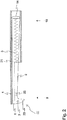
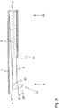
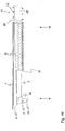
- the show Figures 2 (Side view) and 4 (top view) a support element or frame element 1, in which the actual locking element 2 is guided.
- this frame member 1 which may be made of a plastic, for example, the entire assembly, as shown in the mentioned figures, on the body 18, in particular between a ceiling area bounding the interior and attached to the outside of the body 18 Ceiling panel of the dishwasher GS, are fixed, so that as a result, a movement of the locking element 2 relative to the body 18 of the dishwasher GS is possible.
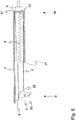
- the locking arrangement comprises a force accumulator 5, which acts on the locking element 2 with a closing force, with the aid of which it from the open position OS (shown in the Figures 2 and 4 ) in a locking position VS (see Figures 3 and 5 ) is movable.
- the open position OS is defined as the position in which an approach of the door 19 in the front region 9 of the locking arrangement is possible, the locking element 2 thus not yet with a corresponding holding element 3 (see, for. FIG. 11 , which shows a corresponding retaining element 3 in the form of a recess projecting into the door 19,) of the door 19 is engaged.
- the locking position VS is defined as the position in which the locking element 2, for example via the nose 23 shown in the figures, with the Holding member 3 is engaged and thereby locks the door 19 relative to the body 18.
- the locking element 2 is in the open position, wherein it is preferably in contact with a stop surface 6, which prevents premature movement into the locking position. If now the door 19 is closed by an operator, then it is necessary for the locking element 2 to come out of engagement with the stop surface 6.
- the locking element 2 preferably has a release element 7, which in the FIGS. 2 to 5 is exemplified as a laterally projecting bolt.
- the door 19 should expediently have a corresponding, for example, wedge-shaped counter element which, upon contact with the release element 7, causes the front region 9 of the locking element 2 to move downward, so that it can slide over the stop surface 6.
- a release element 7 As a release element 7, of course, another construction can be used, which causes the said movement of the locking element 2. It is conceivable, for example, a rotary latch, which undergoes a rotation upon contact with the door 19, wherein this rotation finally results in a movement of the locking element 2, so that it is moved away from the stop surface 6.
- the energy accumulator 5 may be formed, for example, as shown here as a spiral spring, which is supported on the one hand in the region of a rear portion 10 of the locking element 2 and the other on a support surface 21 of the frame member 1, as shown in the FIGS. 2 to 14 is shown. As a result, a force is exerted on the locking element 2, which pulls it in the direction of the rear area 10.
- the door 19 is also drawn to the body 18 and a arranged between the body 18 and door 19 seal, so that leakage of rinsing liquid and / or steam can be excluded.
- the frame element 1 can, as shown, have an additional limiting element 22 to which the Front region 9 of the locking element 2 rests in the locking position.
- the door 19 could be unlocked without such an element.
- a tightening on the door 19 in its closed position would cause the nose 23 and thus also the locking element 2 is pulled against the force of the force accumulator 5 in the direction of its front portion 9.
- the frame member 1 can be equipped with corresponding guide surfaces which cooperate with corresponding mating surfaces of the locking element 2.
- the nose 23 or the holding member 3 have a corresponding shape, which causes said upward movement in contact with the door.
- the locking arrangement additionally has a drive unit 4 with the aid of which the locking element 2 can be moved from the locking position VS against the closing force of the force accumulator 5 into the open position OS.
- drive unit 4 is for this purpose any drive in question, which allows a corresponding movement of the locking element 2 from the locking position VS in the open position OS.
- Conceivable for example, linear drives, electric drives, bimetals or similar responsive to temperature fluctuations components, etc.
- FIGS. 6 and 7 indicated a solution that allows movement of the locking element 2 by means of a linear drive.
- the drive unit 4, not shown, has for this purpose an intermediate member 8, via which the correspondingly generated force can be transmitted to the rear region 10 of the locking element 2.
- the intermediate member 8 may be formed, for example, as a plunger, of a in FIG. 6 shown position in the in FIG. 7 shown position is movable and in this case causes a movement of the locking element 2 in its open position.
- FIGS. 8 to 11 Another way to realize the basic idea of the present invention is in the FIGS. 8 to 11 shown.
- the drive unit 4 is formed by an electric motor, which is preferably connected to the body 18 of the dishwasher GS independently of the carrier element or frame element 1, so that a corresponding retrofitting is possible at any time.
- the drive unit 4 is further connected to a cam 15.
- the operative connection between drive unit 4 and locking element 2 is in turn realized by means of an intermediate member 8, which is formed in the example shown as a rocker arm, which in turn is rotatably supported via a rotation axis 11.
- the axis of rotation 11 is preferably perpendicular in the plane defined by the width direction and depth direction of the body 18, so that the rocker arm sweeps over a pivoting range in this positional plane.
- the cam 15 exerts a force on the first leg 12 of the rocker arm from a certain position, resulting in a rotation of the rocker arm about its axis of rotation 11 of the in FIG. 10 position shown in the position as shown in FIG. 11 is shown.
- a corresponding engagement surface 17 of the second leg 13 of the rocker arm with a contact surface 14 in the rear region 10 of the locking element 2 in contact and thus causes a power transmission of the drive unit 4 via the intermediate member 8 on the locking element 2, which as a result undergoes a movement in the direction of the open position.
- the engagement surface 17 of the intermediate member 8 and the contact surface 14 of the locking element 2 are inclined to each other such that from the intermediate member 8, a force component is transferable to the locking element 2, during the axial movement of the locking element 2 along a Longitudinal axis of the open position in the locking position additionally causes a rotational movement of the locking element 2 about a rotational axis DA, which is perpendicular to the axial or longitudinal longitudinal direction of movement of the locking element.
- the locking arrangement is arranged, for example, in the ceiling region of the body, preferably in the front middle region of the top wall of the body, the longitudinal axis extends in particular in the depth direction of the body of the dishwasher.
- the locking element is thus preferably mounted in this mounting case relative to the carrier element such that it is movable during the movement between the open position and the locking position along a longitudinal axis such as LA, which extends in particular in the depth direction of the body of the dishwasher, and in addition to an axis of rotation such as DA is rotatable, which extends perpendicular to the longitudinal axis LA, in particular in a plane defined by the width and depth direction of the body of the dishwasher layer and substantially parallel to the width direction of the body of the dishwasher extends.
- the axis of rotation DA in each case runs perpendicular to the plane of the drawing.
- This rotational movement and, consequently, an upward movement of the front region 9 of the locking element 2 from a locking position to an open position can be realized, for example, by the engagement surface 17 of the intermediate element, in particular rocker arm, as shown in FIGS FIGS. 8 and 9 seen, bevelled.
- This will be in contact with the vertically extending contact surfaces 14 of the locking element 2 transmit a force component to the locking element, which causes said rotational movement of the locking element 2.
- this will rotate due to the said force component to an imaginary axis of rotation DA positioned in the rear region 10 and thus the in the Figures 9 and 11 shown position.
- both surfaces can be provided accordingly with an inclination.
- FIG. 11 This shows next to the locking arrangement 25 according to the invention also a possible positioning of the same.
- the frame element 1 on the upper side of the already mentioned body 18 of a dishwasher GS, wherein this can have an opening 20 in its region facing the door 19 through which a part of the locking element 2, for. B. the nose 23, at least in the locking position can protrude to engage with a corresponding holding element 3, for example, arranged in the door 19 recess in engagement.
- the door 19 in FIG. 11 still a gap is opened. To activate the closing mechanism, it would therefore have to be moved further in the direction of the body 18 until the holding element 3 is located under the nose 23 of the locking element 2.
- the intermediate member 8 with a return element 16 are in operative connection, which always ensures that the engagement surface 17 of the intermediate member 8 is in contact with the locking element 2 only when the drive unit 4 a Force on the intermediate member 8 transmits. If this is not the case, the intermediate member 8 is moved back to its starting position, as exemplified in FIG. 10 is shown.
- the use of a cam for actuating the intermediate member has, in particular, the advantage of a shorter unlocking time relative to an eccentric, i. already after a 90 ° rotation of the cam, the intermediate member can be actuated and the locking element can be brought into its open position. After a further 90 ° rotation of the cam, the intermediate member is already released again, i. no longer in contact with the rear area of the locking element, so that it can be brought into its locking position, if necessary, e.g. the user wants to close the door. An uncomfortable, too long waiting time between the time of unlocking the door and the time from which a door lock is possible again, is thus avoided.
- the eccentric requires in comparison to the cam of the drive unit from a lower torque due to its flatter attack surface slope when contacting the intermediate member. Also, the envelope of the rotational movement of the eccentric is more space-saving than that of the cam.
- FIGS. 12 and 13 show a further embodiment of the invention, in which the drive unit 4 is also formed by an electric motor, which is preferably connected independently of the support member or frame member 1 with the body 18 of the dishwasher GS.
- a connecting element in the form of a rotary arm 45 is rotatably connected to a rotatable shaft 46 of the electric motor.
- a driver 47 rotatably mounted on the shaft 46.
- the axis of rotation of the driver 47 is preferably perpendicular to the plane defined by the width direction and depth direction of the body 18 level.
- the connecting element can also be designed otherwise, for example as a turntable.
- the operative connection between drive unit 4 and locking element 2 is in turn realized by means of an intermediate member 8, which in the example shown is in turn designed as a rocker arm, which is rotatably mounted via a rotation axis 11.
- the axis of rotation 11 of the rocker arm is preferably perpendicular to that of the Width direction and depth direction of the body 18 spanned plane, so that the rocker arm sweeps over a pivoting range in this positional plane.
- the first leg 12 of the rocker arm is guided in the driver 47, that is, movably mounted in the driver 47 in the longitudinal direction of the first leg 12.
- the rotary arm 45 executes a rotational movement which, due to the bearing of the first leg 12 of the rocker arm in the driver 47, results in a rotation of the rocker arm about the axis of rotation 11.
- the rocker arm of the in FIG. 12 position shown in a position as shown in FIG. 13 is shown turned.
- a corresponding engagement surface 17 of the second leg 13 of the rocker arm with the contact surface 14 in the rear portion 10 of the locking member 2 in contact and thus causes a power transmission from the drive unit 4 via the intermediate member 8 on the locking element 2, as a result, a movement in the direction the open position learns.
- FIG. 11 Analogous to FIG. 11 also shows FIG. 13 in addition to the locking arrangement 25 according to the invention a possible positioning thereof. Again, to avoid repetition to the corresponding statements FIG. 11 directed.
- the embodiment is characterized according to the Figures 12 and 13 by a particularly space-saving arrangement, which in particular results from the fact that the circle spanned by the movement of the rotary arm 45 is fully utilized.
- the drive unit 4 is a force storage 26.
- This can be designed in principle arbitrary, but is preferably designed as a spring element, for example as a helical compression spring 27.
- a Bowden cable 28 controllable locking device 29 of the energy storage in the in the Figures 12 and 13 shown locking position of the locking element 2 held in a prestressed, energy-storing state. If required, so if the door of the dishwasher GS is to be opened automatically, the locking device 29 releases the energy storage device 26, so that it can move the locking element 2 in the open position OS.
- the energy storage device 26 further comprises a guide rod 30, at whose end facing the locking element 2 arranged approximately as a pressure plate 31, serving to initiate the compressive force of the helical compression spring 27 in the locking element 2 organ.
- the helical compression spring 27 is supported at one end to the pressure plate 31 and at its other end to a transverse to the direction of movement of the locking element 2 extending support wall 32, wherein it engages around the guide rod 30.
- the guide rod 30 passes axially through an opening 33 in the support wall 32.
- the guide rod 30 carries a radially beyond its peripheral surface standing out, for example, designed as a flange stop element 34.
- This element is part of the locking device 29, which further comprises a cooperating with the stop element 34 blocking element 35.
- the blocking element 35 is movable on a direction transverse to the movement path of the guide rod 30 extending direction, which is indicated by the double arrow 36.
- the blocking element 35 In the Locking position VS of the locking element 2, the blocking element 35 is disposed between the stop member 34 and the support wall 32, wherein it is clamped due to the located in a compressed state, so biased, helical compression spring 27 between the stopper member 34 and support wall 32.
- the locking device 29 is, as I said, controllable, and when the appliance door is to be opened, moved to the release position in which it is outside of the movement path described by the stop element 34.
- the blocking element 35 by means of the Bowden cable 28, the inner cable 37 is connected to the blocking element 35, in the direction of the arrow 39 of the guide rod 30 against the action of the inner cable 37 encompassing helical compression spring 40 moves away. Due to the action of the relaxing helical compression spring 27 then the locking element 2 is moved to its open position OS. At the end of this movement, the stop element 34 abuts against the support wall 32.
- the measured in the axial direction of the guide rod 30 length of the blocking element 35 substantially corresponds to the distance which the locking element 2 travels viewed in the axial direction of the guide rod 30 when it moves from its locking position VS in its open position OS.
- the helical compression spring 27 can be tensioned again with the aid of an actuator 41, which is indicated only schematically.
- the drive unit 4 is designed as an electromagnet 42, which comprises a coil 43 and a coil 43 at least partially surrounded and movable in the axial direction of the coil 43 core or armature 44 made of ferromagnetic material.
- electromagnet 42 which comprises a coil 43 and a coil 43 at least partially surrounded and movable in the axial direction of the coil 43 core or armature 44 made of ferromagnetic material.
- the armature 44 can be driven by a reverse current flow through the coil 43 back to its original position.
- the embodiment according to FIG. 14 has the particular advantage that the drive unit 4 embodied as an electromagnet 42 can at the same time be used as a sensor for detecting an opening request for the door 19. So, for example, by a light Pressing the door 19 in the door seal causes a movement of the spring-biased locking element 2 in the direction of the armature 44 to. This also causes a movement of the armature 44, which induces a voltage in the coil 43, which can be detected and used as a trigger signal for an automatic door opening.
- FIG. 17 finally shows a schematic block diagram of a household appliance according to the invention using the example of the dishwasher GS.
- This includes a door control TS, which upon receipt of an opening signal drives the drive unit 4 of the locking arrangement 25 such that the locking element 2 moves from the locking position VS against the closing force into the open position OS.
- An opening signal can on the one hand be transmitted to the door control by a program sequence control PS which controls the program sequences of the dishwasher.
- the program sequence control PS and the door control TS can be realized in a common control unit or separately from each other.
- the opening signal can be generated and transmitted by the program sequence control PS as a function of the program sequence and / or of one or more operating parameters of the dishwasher. In this way, a program-controlled opening of the door 19 is made possible.
- the drive unit 4 can be activated by the door control TS, for example, following the specification of a wash program, preferably after completion of a drying phase in which items to be washed are arranged inside the dishwasher.
- an opening signal can also be generated and transmitted by a sensor system S, which is designed to detect an opening request of a user of the dishwasher.
- the sensor can be e.g. Touch sensors and / or proximity sensors and / or knock sensors (structure-borne sound sensors) and / or magnets and / or other optical and / or acoustic sensors and / or inductive and / or capacitive sensors.
- the door 19 is opened by means of an opening device OV at least one gap, so that they are then fully opened by the user in case of need can.
- the opening device OV can be realized in a variety of ways, for example with the aid of spring elements or other actuators, such as a plunger for regurgitation of the door 19.
- the invention has been explained by way of example for a dishwasher but is basically also applicable to other household appliances with locking arrangements for locking a door of the household appliance.
- the locking arrangement is respectively attached to the body 18 of the domestic appliance and cooperates with a arranged on the door 19 corresponding holding element 3.
- the locking arrangement can also be fastened to the door 19 and accordingly cooperate with a holding element 3, which is arranged on the body 18.
Abstract
Description
Die Erfindung betrifft eine Verriegelungsanordnung zum Verriegeln einer Tür eines Haushaltsgeräts, insbesondere einer Geschirrspülmaschine, wobei die Verriegelungsanordnung an der Tür oder an einem die Tür tragenden Korpus des Haushaltsgeräts befestigbar ist, wobei die Verriegelungsanordnung ein Verriegelungselement umfasst, welches zwischen einer Offenstellung und einer Verriegelungsstellung, in der es mit einem Halteelement an dem Korpus bzw. an der Tür in Eingriff bringbar ist, bewegbar ist, und wobei die Verriegelungsanordnung einen Kraftspeicher aufweist, der das Verriegelungselement mit einer Schließkraft beaufschlagt, mit dessen Hilfe es von der Offenstellung in die Verriegelungsstellung bewegbar ist. Darüber hinaus wird ein Haushaltsgerät mit einem Korpus und einer Tür beschrieben, die zwischen einer geöffneten Stellung und einer geschlossenen Stellung, in welcher der Korpus mit Hilfe der Tür verschlossen ist, bewegbar ist, wobei das Haushaltsgerät eine Verriegelungsanordnung aufweist, mit deren Hilfe die Tür in der geschlossenen Stellung verriegelbar ist.The invention relates to a locking arrangement for locking a door of a household appliance, in particular a dishwasher, wherein the locking arrangement on the door or on a door-carrying body of the household appliance can be fastened, wherein the locking arrangement comprises a locking element which between an open position and a locking position, in it is movable with a holding element on the body or on the door is engageable, and wherein the locking arrangement comprises a force accumulator, which acts on the locking element with a closing force by means of which it is movable from the open position to the locking position. In addition, a household appliance is described with a body and a door which is movable between an open position and a closed position in which the body is closed by means of the door, wherein the household appliance has a locking arrangement, with the help of the door in the closed position is locked.
Im Stand der Technik ist es z.B. bekannt, die Tür oder den Korpus einer Geschirrspülmaschine mit einer Verriegelungsanordnung zu versehen, die eine Verriegelung der Tür in ihrer geschlossenen Stellung sicherstellt, so dass ein Austreten von Spülflüssigkeit und/oder Dampf während des Betriebs der Geschirrspülmaschine verhindert werden kann. Weiterhin sind Systeme bekannt, mit deren Hilfe sich die Tür einer Geschirrspülmaschine automatisch entriegeln lässt. Derartige Lösungen sind jedoch meist recht aufwendig konstruiert und damit fehleranfällig.In the prior art it is e.g. It is known to provide the door or the body of a dishwasher with a locking arrangement which ensures a locking of the door in its closed position, so that leakage of rinsing liquid and / or steam during operation of the dishwasher can be prevented. Furthermore, systems are known, with the help of which the door of a dishwasher can be unlocked automatically. However, such solutions are usually designed quite expensive and thus error-prone.
Aufgabe der Erfindung ist es daher, eine verbesserte Verriegelungsanordnung für eine Tür eines Haushaltsgeräts, insbesondere einer Geschirrspülmaschine, vorzuschlagen.The object of the invention is therefore to propose an improved locking arrangement for a door of a household appliance, in particular a dishwasher.
Gelöst wird die Aufgabe mit Hilfe einer Verriegelungsanordnung mit den Merkmalen gemäß unabhängigem Anspruch 1.The problem is solved by means of a locking arrangement with the features according to
Die vorgeschlagene Verriegelungsanordnung zeichnet sich erfindungsgemäß dadurch aus, dass sie neben dem genannten Kraftspeicher, der das Verriegelungselement mit einer Schließkraft beaufschlagt, mit dessen Hilfe es von der Offenstellung in die Verriegelungsstellung bewegbar ist, eine Antriebseinheit aufweist, mit deren Hilfe das Verriegelungselement von der Verriegelungsstellung gegen die Schließkraft in die Offenstellung bewegbar ist.The proposed locking arrangement according to the invention is characterized in that it next to the said energy storage, which acts on the locking element with a closing force, by means of which it is movable from the open position to the locking position, a drive unit, with the aid of the locking element of the locking position against the closing force is movable into the open position.
Die erfindungsgemäße Verriegelungsanordnung weist gegenüber den aus dem Stand der Technik bekannten Vorrichtungen zahlreiche Vorteile auf. Zunächst wird die Tür durch die Kraft des Kraftspeichers sicher in ihrer geschlossenen Stellung gehalten, sobald das Verriegelungselement in seine Verriegelungsstellung bewegt wurde. Der Kraftspeicher, der vorzugsweise als mechanischer Kraftspeicher ausgebildet ist, stellt somit ein zuverlässiges Verriegeln der Tür auch bei einem kurzzeitigen Ausfall der Stromversorgung sicher. Weiterhin kann auch ein händisches Öffnen der Tür weiterhin ermöglicht werden. Wird nämlich die Tür unter Aufwand einer entsprechenden Gegenkraft in Richtung ihrer Offenstellung bewegt, so kann das Verriegelungselement bei entsprechender Ausgestaltung desselben gegen die Schließkraft des Kraftspeichers in seine Offenstellung bewegt werden, in der es das korrespondierende Halteelement an dem Korpus oder an der Tür, das beispielsweise als Vertiefung ausgebildet ist, freigibt. Die Tür kann schließlich vollständig geöffnet werden. Des Weiteren ist es mit Hilfe der Antriebseinheit auch möglich, das Verriegelungselement automatisch in seine Offenstellung zu verfahren. Dies ermöglicht schließlich die Verwendung der Verriegelungsanordnung in Haushaltsgeräten, wie z.B. Geschirrspülmaschinen, die mit einer so genannten grifflosen Frontverkleidung versehen sind. Dies ist insbesondere bei sogenannten Einbaugeräten, wie Einbau-Geschirrspülmaschinen, zweckmäßig, die zum Einbau in eine Einbauküche vorgesehen sind. Ein Öffnungswunsch für die Tür des Haushaltsgeräts kann dabei mit Hilfe einer geeigneten Sensorik, z.B. in Form von Berührungssensoren, Näherungssensoren, Klopfsensoren, Magneten, sonstigen optischen oder akustischen Sensoren oder auch induktiven oder kapazitiven Sensoren, detektiert werden. Bei Detektion eines Öffnungswunsches kann dann ein Öffnungssignal an eine Türsteuerung übermittelt werden, welche daraufhin die Antriebseinheit derart ansteuert, dass sich das Verriegelungselement von der Verriegelungsstellung gegen die Schließkraft in die Offenstellung bewegt und damit das Verriegelungselement außer Eingriff mit dem korrespondierenden Halteelement bringt. Ebenso ist es möglich, eine Programmablaufsteuerung des Haushaltsgeräts mit der Türsteuerung zu verbinden. Abhängig vom Programmablauf und/oder von einem oder mehreren Betriebsparametern des Haushaltsgeräts kann dann auch von der Programmablaufsteuerung ein Öffnungssignal an die Türsteuerung übermittelt werden. Auf diese Weise ist auch ein programmgesteuertes Öffnen der Verriegelungsanordnung möglich, z. B. am Ende einer Trocknungsphase, in der ein in einer Geschirrspülmaschine gereinigtes Spülgut getrocknet wird.The locking arrangement according to the invention has numerous advantages over the devices known from the prior art. First, the door is held securely in its closed position by the force of the force accumulator as soon as the locking element has been moved to its locking position. The energy storage, which is preferably designed as a mechanical energy storage, thus ensuring a reliable locking of the door even with a momentary failure of the power supply. Furthermore, a manual opening of the door can still be made possible. Namely, the door moves under effort of a corresponding counterforce in the direction of its open position, the locking element can be moved with the same configuration against the closing force of the energy storage in its open position, in which it is the corresponding holding element on the body or on the door, for example is formed as a recess releases. The door can finally be fully opened. Furthermore, it is also possible with the help of the drive unit to automatically move the locking element in its open position. This finally allows the use of the locking arrangement in household appliances, such as dishwashers, which are provided with a so-called handle-less front panel. This is particularly useful in so-called built-in appliances, such as built-in dishwashers, expedient, which are intended for installation in a fitted kitchen. An opening request for the door of the household appliance can be detected by means of suitable sensors, for example in the form of touch sensors, proximity sensors, knock sensors, magnets, other optical or acoustic sensors or inductive or capacitive sensors. Upon detection of a desire opening an opening signal can then be transmitted to a door control, which then controls the drive unit such that the locking element moves from the locking position against the closing force in the open position and thus brings the locking element out of engagement with the corresponding holding element. Likewise, it is possible to have one Program sequence control of the household appliance to connect to the door control. Depending on the program flow and / or one or more operating parameters of the household appliance, an opening signal can then also be transmitted to the door control by the program sequence control. In this way, a program-controlled opening of the locking arrangement is possible, for. B. at the end of a drying phase in which a washed in a dishwasher ware is dried.
Nachdem die Verriegelungsanordnung aktiviert und entsprechend außer Eingriff mit dem Halteelement gebracht ist, kann das eigentliche, zumindest spaltweise Öffnen der Tür mit Hilfe einer Öffnungsvorrichtung, zum Beispiel in Form von Federelementen und/oder mit Hilfe von weiteren Aktuatoren, wie z.B. einem Aufstoßelement in Form eines Stößels, welcher auf die Tür einwirkt, realisiert werden. Die weiteren Aktuatoren können vorteilhaft durch die Antriebseinheit der Verriegelungsanordnung angetrieben werden.After the locking arrangement has been activated and correspondingly disengaged from the holding element, the actual, at least gap-wise, opening of the door can be achieved by means of an opening device, for example in the form of spring elements and / or with the help of further actuators, such as e.g. an impact element in the form of a plunger, which acts on the door can be realized. The other actuators can advantageously be driven by the drive unit of the locking arrangement.
Gemäß einer vorteilhaften Weiterbildung der Erfindung ist der Kraftspeicher mindestens eine Feder, insbesondere mindestens eine sich im Wesentlichen longitudinal erstreckende Spiralfeder. Die Feder kann hierbei als Zugfeder ausgebildet sein, die das Verriegelungselement mit einer Kraft beaufschlagt, die es in seine Verriegelungsstellung zieht. Ebenso können Druckfedern zum Einsatz kommen, die sich an entsprechenden Abstützflächen des Verriegelungselements und des Trägerelements bzw. Rahmenelements abstützen können und das Verriegelungselement in die Verriegelungsstellung drücken.According to an advantageous embodiment of the invention, the energy storage is at least one spring, in particular at least one substantially longitudinally extending coil spring. The spring may in this case be designed as a tension spring, which acts on the locking element with a force that pulls it into its locking position. Likewise, compression springs can be used, which can be supported on corresponding support surfaces of the locking element and the support member or frame member and press the locking element in the locking position.
Eine konstruktiv besonders einfache Realisierung der Verriegelungsanordnung ergibt sich, wenn die Verriegelungsanordnung ein Trägerelement oder Rahmenelement umfasst, mit dessen Hilfe die Verriegelungsanordnung an der Tür oder an dem Korpus befestigbar ist, und das Verriegelungselement relativ zum Trägerelement zwischen der Offenstellung und der Verriegelungsstellung bewegbar ist.A structurally particularly simple realization of the locking arrangement results when the locking arrangement comprises a support member or frame member by means of which the locking arrangement is attachable to the door or on the body, and the locking element is movable relative to the support member between the open position and the locking position.
Nach einer vorteilhaften Weiterbildung der Erfindung ist vorgesehen, dass das Trägerelement bzw. Rahmenelement eine Anschlagsfläche aufweist, gegen die das Verriegelungselement in der Offenstellung abstützbar ist, um eine ungewollte Rückbewegung in die Verriegelungsstellung zu verhindern, und dass dem Verriegelungselement ein Freigabeelement zugeordnet ist, mit dessen Hilfe das Verriegelungselement bei einem Kontakt des Freigabeelements mit der Tür außer Eingriff mit der Anschlagsfläche bringbar und von dem Kraftspeicher in die Verriegelungsstellung bewegbar ist. Das Verriegelungselement wird in diesem Fall von der Antriebseinheit ausgehend von seiner Verriegelungsstellung soweit bewegt, dass es schließlich in den Bereich der Anschlagsfläche gelangt und von dieser - vorgespannt von dem Kraftspeicher - gehalten wird. In diesem Stadium kann die Tür geöffnet und z. B. mit Spülgut beladen werden. Wird die Tür wieder geschlossen, so kommt diese ab einer gewissen Stellung mit dem Freigabeelement in Kontakt. Durch Weiterbewegen der Tür wird schließlich von der Tür eine Kraft auf das Freigabeelement übertragen, welches diese Kraft an das Verriegelungselement weiterleitet, wobei das Freigabeelement, das Verriegelungselement und die Anschlagsfläche insbesondere derart ausgebildet und zueinander angeordnet sind, dass die Verriegelungseinheit eine Bewegung erfährt, die es außer Eingriff mit der Anschlagsfläche bringt. Hierdurch wird das Verriegelungselement, das zu diesem Zeitpunkt bereits mit dem Halteelement der Tür in Wirkverbindung steht, freigegeben. Durch die Schließkraft des Kraftspeichers kommt es schließlich zu einer weiteren Bewegung des Verriegelungselements in seine Verriegelungsstellung, wobei die Tür noch weiter an den Korpus herangezogen wird und diesen vollständig verschließt.According to an advantageous embodiment of the invention it is provided that the carrier element or frame element has a stop surface against which the locking element can be supported in the open position to prevent unwanted return movement into the locking position, and that the Locking element is associated with a release element, with the aid of which the locking element can be brought into contact with the contact surface of the release element and out of engagement with the stop surface of the power storage in the locking position. In this case, the locking element is moved by the drive unit starting from its locking position until it finally reaches the area of the abutment surface and is held by the drive unit - biased by the force accumulator. At this stage, the door can be opened and z. B. be loaded with items. If the door is closed again, it comes from a certain position with the release element in contact. By further moving the door, a force is finally transmitted from the door to the release element, which forwards this force to the locking element, wherein the release element, the locking element and the stop surface are in particular designed and arranged to each other that the locking unit undergoes a movement that it disengages with the stop surface brings. As a result, the locking element, which is already in operative connection with the retaining element of the door at this time, is released. By the closing force of the energy storage, there is finally a further movement of the locking element in its locking position, wherein the door is further used on the body and this completely closes.
Gemäß einer vorteilhaften Weiterbildung der Erfindung ist vorgesehen, dass die Verriegelungsanordnung ein Zwischenglied umfasst, das sowohl mit der Antriebseinheit als auch dem Verriegelungselement in Wirkverbindung steht bzw. bringbar ist, und mit dessen Hilfe eine Kraft von der Antriebseinheit auf das Verriegelungselement übertragbar ist, die eine Bewegung des Verriegelungselements von der Verriegelungsstellung in die Offenstellung bewirkt. Das Zwischenglied kann hierbei z. B. als Stößel ausgebildet sein, der von der Antriebseinheit linear gegen das Verriegelungselement bewegt werden kann, um dieses in die Offenstellung zu bewegen. Ebenso können verschiedenste Zahnstangen oder -räder zum Einsatz kommen, welche die Funktion eines oder mehrerer Zwischenglieder übernehmen und letztendlich eine Kraftübertragung von der Antriebseinheit auf das Verriegelungselement gewährleisten. Schließlich können auch Getriebe Verwendung finden, um die Kraft entweder möglichst schnell und/oder möglichst gleichmäßig auf das Verriegelungselement zu übertragen.According to an advantageous embodiment of the invention, it is provided that the locking arrangement comprises an intermediate member which is in operative connection with both the drive unit and the locking element, and with the aid of a force from the drive unit to the locking element is transferable, the one Movement of the locking element causes from the locking position to the open position. The intermediate member may in this case z. B. may be formed as a plunger, which can be moved linearly by the drive unit against the locking element to move this in the open position. Likewise, a variety of racks or wheels can be used, which take over the function of one or more intermediate links and ultimately ensure a power transmission from the drive unit to the locking element. Finally, gear can be used to transfer the power either as quickly and / or as evenly as possible to the locking element.
Nach einer vorteilhaften Weiterbildung der Erfindung ist vorgesehen, dass das Verriegelungselement einen Frontbereich, der mit dem Halteelement der Tür in Eingriff bringbar ist, und einen dem Frontbereich gegenüberliegenden Heckbereich aufweist, wobei das Verriegelungselement und das Zwischenglied derart zueinander angeordnet sind, dass die von der Antriebseinheit erzeugte Kraft auf den Heckbereich übertragbar ist. Der Frontbereich kann hingegen eine Form aufweisen, die einen Eingriff mit dem Halteelement ermöglicht. Beispielsweise kann das Verriegelungselement in einen Nasenabschnitt münden, der in eine entsprechende Vertiefung der Tür eingreifen kann. Im Gegensatz hierzu weist der Heckbereich vorzugsweise eine Kontaktfläche auf, auf die das Zwischenglied oder auch direkt die Antriebseinheit einwirken kann. Während der Frontbereich zweckmäßigerweise von außen zugänglich ausgebildet ist, damit er mit dem Halteelement der Tür in Kontakt kommen kann, kann der Heckbereich geschützt zwischen einer Wandung des Korpus und einer entsprechenden Verkleidung oder einer Arbeitsplatte verborgen angeordnet werden, so dass dieser Bereich und bei Bedarf auch die Antriebseinheit vor Beschädigungen geschützt sind.According to an advantageous development of the invention, it is provided that the locking element has a front area which can be brought into engagement with the retaining element of the door and a rear area opposite the front area, wherein the locking element and the intermediate element are arranged relative to one another in such a way that the drive unit generated force is transferable to the rear area. The front portion, however, may have a shape that allows engagement with the retaining element. For example, the locking element can open into a nose portion which can engage in a corresponding recess of the door. In contrast, the rear region preferably has a contact surface on which the intermediate member or directly the drive unit can act. While the front portion is expediently adapted to be accessible from outside so that it can come into contact with the retaining element of the door, the rear portion can be concealed between a wall of the body and a corresponding panel or worktop, so that this area and if necessary also the drive unit is protected against damage.
Gemäß einer vorteilhaften Weiterbildung der Erfindung ist vorgesehen, dass das Zwischenglied als Kipphebel ausgebildet ist, der um eine Drehachse drehbar gelagert ist, wobei der Kipphebel einen ersten Schenkel aufweist, der mit der Antriebseinheit in Wirkverbindung steht bzw. bringbar ist, und wobei der Kipphebel einen zweiten Schenkel aufweist, der mit einer Kontaktfläche des Verriegelungselements in Kontakt steht bzw. bringbar ist, wobei der Kipphebel mit Hilfe der Antriebseinheit in eine Drehbewegung versetzbar ist, während der der Kipphebel eine Kraft auf die Kontaktfläche überträgt, die eine Bewegung des Verriegelungselements in die Offenstellung bewirkt. Ein besonderer Vorteil der Verwendung eines entsprechenden Kipphebels liegt in der Tatsache, dass dieser äußerst robust konstruiert werden kann und damit eine hohe Belastbarkeit aufweist. Zum anderen kann durch die Wahl der einzelnen Schenkellängen eine genaue Anpassung der Kraftübertragung zwischen Antriebseinheit und Verriegelungselement erfolgen. So kann zum Beispiel durch eine Vergrößerung des Längenverhältnisses zwischen dem ersten und dem zweiten Schenkel, also beispielsweise durch eine Verlängerung des ersten Schenkels, erreicht werden, dass aufgrund des verbesserten Hebelverhältnisses eine schnellere und/oder leistungsschwächere und/oder kostengünstigere und/oder hinsichtlich ihrer Bauform kleinere Antriebseinheit eingesetzt werden kann. Darüber hinaus ergibt sich aus der Verwendung des genannten Kipphebels die Möglichkeit, die Antriebseinheit platzsparend neben, insbesondere seitlich neben, dem Trägerelement bzw. Rahmenelement anzuordnen, so dass die gesamte Verriegelungsanordnung vorzugsweise im Frontbereich des Korpus einer Geschirrspülmaschine nebeneinanderliegend angeordnet werden kann.According to an advantageous embodiment of the invention, it is provided that the intermediate member is designed as a rocker arm which is rotatably mounted about an axis of rotation, wherein the rocker arm has a first leg, which is in operative connection with the drive unit or can be brought, and wherein the rocker arm a second leg, which is in contact with or can be brought into contact with a contact surface of the locking element, wherein the rocker arm is set into a rotational movement by means of the drive unit, during which the rocker arm transmits a force to the contact surface, the movement of the locking element in the open position causes. A particular advantage of using a corresponding rocker arm lies in the fact that it can be constructed extremely robust and thus has a high load capacity. On the other hand can be done by choosing the individual leg lengths accurate adjustment of the power transmission between the drive unit and locking element. Thus, for example, by increasing the length ratio between the first and the second leg, that is to say for example by lengthening the first leg, it is possible that due to the improved lever ratio a faster and / or lower-power and / or less expensive and / or with regard to their design smaller drive unit can be used. In addition, results from the use of said rocker arm the possibility of space-saving next to the drive unit, in particular laterally, to arrange the support element or frame element, so that the entire locking arrangement can preferably be arranged side by side in the front region of the body of a dishwasher.
Der Kipphebel kann zumindest in einem Teilbereich, insbesondere im Bereich des ersten Schenkels, auch derart elastisch verformbar ausgeführt sein, dass er ab einer vorgebbaren Kraft nachgibt oder ausweicht, was zur Folge hat, dass keine oder zumindest keine für ein außer Eingriffbringen des Verriegelungselements mit dem Halteelement der Tür ausreichende Kraft mehr auf das Verriegelungselement übertragen wird. Durch eine derartige Ausgestaltung des Kippehebels wird automatisch eine Kraftbegrenzung realisiert, welche als Schutz vor Überlast für die Verriegelungsanordnung dient. Eine Überlast, welche ohne Kraftbegrenzung auch zu einer Beschädigung von Komponenten der Verriegelungsanordnung, weiterer an dem automatischen Öffnungsvorgang der Tür beteiligter Komponenten oder auch der Tür selbst führen könnte, kann beispielsweise dann auftreten, wenn während des Öffnungsvorganges der Tür eine hohe Gegenkraft, z.B. durch einen Benutzer oder ein Hindernis, auf die Tür ausgeübt wird.The rocker arm, at least in a partial area, in particular in the region of the first leg, can also be made so elastically deformable that it yields or deflects from a predefinable force, with the result that none or at least none for disengaging the locking element with the Retaining element of the door sufficient force is transmitted to the locking element. By such a configuration of the tilt lever, a force limitation is automatically realized, which serves as protection against overload for the locking arrangement. An overload, which without force limitation could also lead to damage of components of the locking arrangement, further components involved in the automatic opening process of the door or the door itself, can occur, for example, if a high counterforce, e.g. by a user or an obstacle on the door is exercised.
Ein derartiger elastischer Kipphebel ist außerdem auch im Zusammenhang mit einer sogenannten Kindersicherung vorteilhaft, welche ein ungewolltes Öffnen der Tür, insbesondere durch Kinder, verhindert. Eine Kindersicherung könnte z.B. derart realisiert sein, dass das Verriegelungselement bei aktivierter Kindersicherung mit Hilfe eines Blockierelements blockiert ist. In diesem Fall würde die durch das Blockierelement ausgeübte Gegenkraft auch dazu führen, dass der Kipphebel aufgrund seiner elastischen Eigenschaften nachgibt oder ausweicht.Such an elastic rocker arm is also advantageous in connection with a so-called child safety, which prevents unintentional opening of the door, especially by children. A parental control could e.g. be realized in such a way that the locking element is blocked with activated child safety lock by means of a blocking element. In this case, the counterforce exerted by the blocking element would also lead to the rocker arm yielding or evading due to its elastic properties.
Alternativ könnte eine Kindersicherung aber auch dadurch realisiert sein, dass die Antriebseinheit bei aktivierter Kindersicherung außer Funktion gesetzt wird. So könnte beispielsweise die Stromzufuhr zu einer elektrischen Antriebseinheit, z.B. mit Hilfe eines Mikroschalters, unterbrochen werden.Alternatively, however, a child safety device could also be realized by the drive unit being deactivated when the child safety device is activated. For example, the power supply to an electric drive unit, e.g. with the help of a microswitch, be interrupted.
Nach einer vorteilhaften Weiterbildung der Erfindung ist vorgesehen, dass die Antriebseinheit einen drehbaren Nocken oder einen Exzenter oder dergleichen aufweist, der mit dem ersten Schenkel in Kontakt steht bzw. bringbar ist, wobei mit Hilfe des Nockens oder Exzenters eine Kraft der Antriebseinheit auf den ersten Schenkel übertragbar ist, die eine Drehung des Kipphebels bewirkt. Hierdurch kann eine Drehbewegung der Antriebseinheit, die beispielsweise als Elektromotor ausgebildet sein kann, auf einfache Weise in eine Kippbewegung des Kipphebels umgewandelt werden. Es kann zudem ausreichend sein, wenn die Antriebseinheit stets nur in eine Richtung angetrieben wird, während der Nocken ein Hin- und Herkippen des Kipphebels erlaubt. Eine Richtungsumkehr der Antriebseinheit ist somit nicht notwendig.According to an advantageous development of the invention, it is provided that the drive unit has a rotatable cam or an eccentric or the like, which is in contact or can be brought into contact with the first limb, with the aid of the cam or eccentric a force of the drive unit being transferable to the first limb, which causes a rotation of the rocker arm. In this way, a rotational movement of the drive unit, which may be formed, for example, as an electric motor, be converted in a simple manner in a tilting movement of the rocker arm. It may also be sufficient if the drive unit is always driven in one direction only, while the cam allows a rocking and tilting of the rocker arm. A reversal of direction of the drive unit is therefore not necessary.
Nach einer weiteren vorteilhaften Weiterbildung der Erfindung weist die Antriebseinheit ein Verbindungselelement, z.B. in Form eines Dreharmes, einer Drehscheibe oder dergleichen, auf. An dem Verbindungselement ist beabstandet zur Drehachse des Verbindungselements ein Mitnehmer angeordnet, in welchem der erste Schenkel des Kipphebels geführt ist. Dabei ist durch eine Drehbewegung des Verbindungselements eine Drehung des Kipphebels bewirkbar. Diese Ausführungsform zeichnet sich durch eine besonders platzsparende Konstruktion aus. Außerdem ist kein gesondertes Rückstellelement zur Rückstellung des Kipphebels erforderlich.According to a further advantageous embodiment of the invention, the drive unit comprises a Verbindungselelement, e.g. in the form of a rotary arm, a turntable or the like, on. At the connecting element spaced apart from the axis of rotation of the connecting element, a driver is arranged, in which the first leg of the rocker arm is guided. In this case, a rotation of the rocker arm can be effected by a rotational movement of the connecting element. This embodiment is characterized by a particularly space-saving design. In addition, no separate return element for returning the rocker arm is required.
Gemäß einer vorteilhaften Weiterbildung der Erfindung ist vorgesehen, dass das Zwischenglied mit einem Rückstellelement, insbesondere in Form einer Spiral- oder Drehfeder, in Kontakt steht, das den Kipphebel mit einer Kraftkomponente beaufschlagt, die entgegen der von der Antriebseinheit auf das Zwischenglied übertragbaren Kraft wirkt. Das Zwischenglied muss in diesem Fall von der Antriebseinheit von einer Ausgangsstellung lediglich soweit bewegt werden, dass es eine Bewegung des Verriegelungselements von der Verriegelungsstellung in die Offenstellung bewirkt. Hingegen wird das Zwischenglied im Anschluss daran von dem Rückstellelement wieder ohne weiteres Zutun der Antriebseinheit in die Ausgangsstellung zurückverfahren. Die Antriebseinheit muss in diesem Fall nicht form- oder kraftschlüssig mit dem Zwischenglied verbunden sein, um dieses wieder in die Ausgangsstellung zurückholen zu können. Vielmehr ist es ausreichend, wenn die Antriebseinheit, beispielsweise mittels einem Nocken, ausschließlich eine Bewegung des Zwischenglieds in eine Richtung bewirkt, die das Verriegelungselement in seine Offenstellung bewegt, während die Rückbewegung des Zwischenglieds, durch die schließlich auch eine Rückbewegung des Verriegelungselements beim Schließen der Tür in seine Verriegelungsstellung möglich wird, durch das Rückstellelement erfolgt.According to an advantageous embodiment of the invention, it is provided that the intermediate member is in contact with a return element, in particular in the form of a spiral or torsion spring, which acts on the rocker arm with a force component which acts counter to the transferable force from the drive unit to the intermediate member. In this case, the intermediate member only has to be moved by the drive unit from a starting position to the extent that it causes the locking element to move from the locking position into the open position. On the other hand, the intermediate member is subsequently returned to the starting position by the return element without any further action by the drive unit. The drive unit must not be positively or non-positively connected in this case with the intermediate member in order to bring this back to the starting position can. Rather, it is sufficient if the drive unit, for example by means of a cam, only causes a movement of the intermediate member in a direction which moves the locking element in its open position, while the return movement of the intermediate member, by the finally a return movement of the Locking element when closing the door in its locking position is possible, done by the return element.
Nachdem das Verriegelungselement mit Hilfe der erfindungsgemäßen Verriegelungsanordnung in seine Offenstellung bewegt wurde, kann das eigentliche zumindest spaltweise Öffnen der Tür mit Hilfe einer Öffnungsvorrichtung, z.B. in Form von Federelementen, erfolgen, welche beispielsweise im Bereich eines Türscharniers angeordnet sein können. Alternativ dazu kann zum eigentlichen Öffnen der Tür aber auch mindestens ein Aufstoßelement, z.B. in Form eines Stößels, vorgesehen sein, welches auf die Tür einwirkt und diese dabei aufstößt. Vorteilhaft werden das oder die Aufstoßelemente dabei ebenfalls durch die Antriebseinheit der Verriegelungsanordnung angetrieben. Dabei kann die Antriebseinheit unmittelbar oder über ein Zwischenglied, z.B. den beschriebenen Kipphebel, auf das Aufstoßelement einwirken.After the locking element has been moved into its open position with the aid of the locking arrangement according to the invention, the actual opening of the door at least in the manner of a gap can be effected by means of an opening device, e.g. in the form of spring elements, which can be arranged, for example, in the region of a door hinge. Alternatively, however, at least one impact element, e.g. in the form of a plunger, be provided, which acts on the door and thereby pushes. Advantageously, the or the impact elements are also driven by the drive unit of the locking arrangement. In this case, the drive unit can be directly or via an intermediate member, e.g. the described rocker arm, act on the impact element.
Nach einer vorteilhaften Weiterbildung der Erfindung ist vorgesehen, dass das Verriegelungselement, z.B. gegenüber dem Trägerelement bzw. Rahmenelement, derart gelagert ist, dass es während der Bewegung zwischen der Offenstellung und der Verriegelungsstellung entlang einer Längsachse beweglich ist und zusätzlich um eine Drehachse drehbar ist, die sich senkrecht zur Längsachse erstreckt. Die Längsachse erstreckt sich insbesondere in Tiefenrichtung des Korpus des Haushaltsgeräts, und ist zusätzlich um eine Drehachse drehbar, die sich senkrecht zur Längsachse insbesondere in einer von der Breiten- und Tiefenrichtung des Korpus des Haushaltsgeräts aufgespannten Lageebene sowie im Wesentlichen parallel zur Breitenrichtung des Korpus des Haushaltsgeräts erstreckt. Das Verriegelungselement kann hierdurch auf einfache Weise einen Eingriff mit dem Halteelement und zusätzlich ein Heranziehen der Tür an den Korpus bewirken. Beispielsweise kann die Verriegelung hierbei folgendermaßen erfolgen: Zunächst bewirkt ein Annähern der Tür, beispielsweise mit Hilfe des bereits beschriebenen Freigabeelements, eine Bewegung des Verriegelungselements um seine Drehachse, während der es von einer entsprechenden Abstützfläche wegbewegt wird. Zudem bewirkt die Drehbewegung, dass das Verriegelungselement, z. B. mittels einer im Frontbereich angeordneten Nase, in Eingriff mit dem zum Verriegelungselement korrespondierenden Halteelement gelangt. Im Anschluss daran bewirkt schließlich der Kraftspeicher eine Bewegung des Verriegelungselements in seine Verriegelungsstellung, während der es auch die Tür weiter an den Korpus zieht. Im Gegenzug erfolgt während des Öffnens der Verriegelungsanordnung zunächst eine Bewegung des Verriegelungselements entlang seiner Längsachse und gleichzeitig oder anschließend eine Drehung um seine Drehachse, die vorzugsweise im Heckbereich angeordnet ist, so dass am Ende der Bewegung ein Öffnen der Tür möglich ist.According to an advantageous embodiment of the invention it is provided that the locking element, for example relative to the support member or frame member, is mounted such that it is movable during movement between the open position and the locking position along a longitudinal axis and is additionally rotatable about a rotation axis, the extending perpendicular to the longitudinal axis. The longitudinal axis extends in particular in the depth direction of the body of the household appliance, and is additionally rotatable about an axis of rotation which is perpendicular to the longitudinal axis, in particular in a plane defined by the width and depth direction of the body of the household appliance position plane and substantially parallel to the width direction of the body of the household appliance extends. The locking element can thereby cause a simple way of engagement with the holding element and additionally pulling the door to the body. For example, the locking can take place as follows: First, an approaching of the door, for example by means of the release element already described, causes a movement of the locking element about its axis of rotation, during which it is moved away from a corresponding support surface. In addition, the rotational movement causes the locking element, for. B. by means of a nose arranged in the front area, engages in engagement with the locking element corresponding to the holding element. Following this, finally, the energy storage causes a movement of the locking element in its locking position during which it also pulls the door to the body. In return, during the opening of the locking arrangement, first a movement of the locking element along its longitudinal axis and simultaneously or subsequently a rotation about its axis of rotation, which is preferably arranged in the rear area, so that at the end of the movement opening of the door is possible.
Gemäß einer vorteilhaften Weiterbildung der Erfindung ist vorgesehen, dass das Zwischenglied eine Angriffsfläche und das Verriegelungselement eine Kontaktfläche aufweisen, die wenigstens teilweise miteinander in Kontakt stehen bzw. bringbar sind, wobei die Angriffsfläche und die Kontaktfläche derart zueinander geneigt sind, dass vom Zwischenglied eine Kraftkomponente auf das Verriegelungselement übertragbar ist, die während der Bewegung des Verriegelungselements von der Verriegelungsstellung in die Offenstellung entlang der Längsachse zusätzlich eine Drehbewegung des Verriegelungselements um dessen Drehachse bewirkt. Das Verriegelungselement muss in diesem Fall nicht mehr aktiv, z.B. durch entsprechende Führungen des Trägerelements bzw. Rahmenelements, in seine endgültige Verriegelungsstellung bzw. in den Bereich einer entsprechenden Abstützfläche geführt werden. Vielmehr erfolgt die Drehbewegung am Ende der Bewegung von der Verriegelungsstellung in die Offenstellung durch gezielte Krafteinwirkung von dem Zwischenglied auf das Verriegelungselement. Hierbei kann entweder die Angriffsfläche des Zwischenglieds, die Kontaktfläche oder aber auch beide Flächen bezüglich der Längsachse des Verriegelungselements geneigt sein, um einen entsprechenden Krafteintrag zu ermöglichen, der eine Kraftkomponente aufweist, die nicht parallel zur, insbesondere axialen, Längsbewegungsrichtung des Verriegelungselements verläuft.According to an advantageous development of the invention, it is provided that the intermediate member has an engagement surface and the locking element a contact surface which are at least partially in contact or can be brought, wherein the engagement surface and the contact surface are inclined to each other such that from the intermediate member to a force component the locking element is transferable, which additionally causes a rotational movement of the locking element about its axis of rotation during the movement of the locking element from the locking position to the open position along the longitudinal axis. The locking element no longer needs to be active in this case, e.g. be guided by appropriate guides of the support member or frame member, in its final locking position or in the region of a corresponding support surface. Rather, the rotational movement takes place at the end of the movement from the locking position to the open position by targeted force from the intermediate member to the locking element. In this case, either the engagement surface of the intermediate member, the contact surface or both surfaces with respect to the longitudinal axis of the locking element may be inclined to allow a corresponding force entry having a force component which is not parallel to, in particular axial, longitudinal movement direction of the locking element.
Nach einer vorteilhaften Weiterbildung der Erfindung ist vorgesehen, dass die Antriebseinheit und/oder das Zwischenglied Mittel aufweisen, mit deren Hilfe sie, unabhängig von der Befestigung des Trägerelements bzw. Rahmenelements, am Korpus einer Geschirrspülmaschine befestigbar sind. Auf diese Weise können die Antriebseinheit und/oder das Zwischenglied unabhängig von dem Trägerelement bzw. Rahmenelement und dem darin geführten Verriegelungselement gewartet, ersetzt oder aber auch nachgerüstet werden.According to an advantageous development of the invention, it is provided that the drive unit and / or the intermediate member have means by means of which they can be fastened to the body of a dishwasher, independently of the attachment of the carrier element or frame element. In this way, the drive unit and / or the intermediate member can be serviced, replaced or retrofitted independently of the carrier element or frame element and the locking element guided therein.
Nach einer weiteren vorteilhaften Weiterbildung der Erfindung ist vorgesehen, dass als Antriebseinheit ein Kraftspeicher, insbesondere ein Federelement, z.B. in Form einer Schraubendruckfeder, vorhanden ist. Eine derartige Antriebseinheit ist auch bei begrenztem Bauraum in der Lage, die erforderliche Kraft innerhalb einer kurzen Zeit aufzubringen. Dabei kann eine steuerbare Arretiereinrichtung vorgesehen sein, welche den Kraftspeicher in der Verriegelungsstellung des Verriegelungselements in einem vorgespannten Zustand hält und ihn freigibt, um das Verriegelungselement in die Offenstellung zu bewegen.According to a further advantageous embodiment of the invention, it is provided that a force storage, in particular a spring element, for example in the form of a Helical compression spring, is present. Such a drive unit is able to apply the required force within a short time even with limited space. In this case, a controllable locking device may be provided, which holds the force accumulator in the locked position of the locking element in a prestressed state and releases it to move the locking element in the open position.
Eine weitere Ausführungsform der Erfindung sieht vor, dass als Antriebseinheit ein Elektromagnet vorhanden ist, welcher eine Spule und einen Anker aufweist. Eine derartige Ausführungsform der Antriebseinheit hat den besonderen Vorteil, dass die Antriebseinheit gleichzeitig zur Detektion eines Öffnungswunsches für die Tür genutzt werden kann. Insbesondere kann ein Öffnungswunsch in Abhängigkeit von einer Verschiebung des Ankers relativ zur Spule detektiert werden. Alternativ könnte ein Öffnungswunsch auch mit Hilfe eines Hall-Sensors erfasst werden, welcher die Verschiebung des Ankers sensiert.A further embodiment of the invention provides that the drive unit is an electromagnet which has a coil and an armature. Such an embodiment of the drive unit has the particular advantage that the drive unit can be used simultaneously for detecting an opening request for the door. In particular, an opening request can be detected as a function of a displacement of the armature relative to the coil. Alternatively, an opening request could also be detected by means of a Hall sensor, which senses the displacement of the armature.
Das erfindungsgemäße Haushaltsgerät, z.B. in Form einer Geschirrspülmaschine, zeichnet sich schließlich dadurch aus, dass sie eine Verriegelungsanordnung umfasst, die gemäß einem oder mehreren der beschriebenen Aspekte ausgebildet ist, wobei die Verriegelungsanordnung stets den genannten Kraftspeicher sowie die Antriebseinheit aufweist, so dass vorzugsweise auch ein händisches Ver- und Entriegeln der Verriegelungsanordnung neben der Möglichkeit einer automatischen Entriegelung möglich ist.The household appliance according to the invention, e.g. in the form of a dishwasher, finally characterized by the fact that it comprises a locking arrangement, which is formed according to one or more of the described aspects, wherein the locking arrangement always has the said power storage and the drive unit, so preferably also a manual locking and unlocking the locking arrangement is possible in addition to the possibility of automatic unlocking.
Nach einer vorteilhaften Weiterbildung der Erfindung ist vorgesehen, dass das Verriegelungselement und die Antriebseinheit in einer Frontansicht und/oder Draufsicht des Haushaltsgeräts nebeneinander angeordnet sind. Hierdurch ist die platzsparende Unterbringung, insbesondere in einem Randbereich des Korpus, möglich, der in der Regel stabiler und somit auch tragfähiger ausgebildet ist, als die von den jeweiligen Rand- und Eckenbereichen umgebenen Seiten- bzw. Deckenflächen.According to an advantageous embodiment of the invention it is provided that the locking element and the drive unit are arranged side by side in a front view and / or top view of the household appliance. As a result, the space-saving accommodation, in particular in an edge region of the body, is possible, which is generally more stable and thus also more load-bearing than the side or ceiling areas surrounded by the respective edge and corner areas.
Gemäß einer vorteilhaften Weiterbildung der Erfindung ist vorgesehen, dass die Tür bzw. der Korpus ein Halteelement, insbesondere in Form einer Vertiefung, aufweist, mit dem das Verriegelungselement in der Verriegelungsstellung in Eingriff steht. Das Halteelement muss hierbei in der Regel über keine (aktiv) bewegbaren Elemente verfügen, so dass ein platzsparender Einbau möglich ist. Das Halteelement kann als separates Einsatzstück in den Rahmen der Tür oder in den Korpus eingesetzt sein, oder einteilig mit dem Rahmen der Tür oder mit dem Korpus ausgebildet sein, beispielsweise in Form einer Einprägung oder Nut oder Mulde , in die schließlich das Verriegelungselement eingreifen kann.According to an advantageous development of the invention, it is provided that the door or the body has a holding element, in particular in the form of a depression, with which the locking element engages in the locking position. The holding element As a rule, it must not have any (actively) movable elements so that a space-saving installation is possible. The retaining element can be used as a separate insert piece in the frame of the door or in the body, or be formed integrally with the frame of the door or with the body, for example in the form of an indentation or groove or trough, in which finally the locking element can engage.
Nach einer vorteilhaften Weiterbildung der Erfindung ist vorgesehen, dass das Haushaltsgerät eine Programmablaufsteuerung umfasst, die über eine Türsteuerung mit der Antriebseinseinheit in Verbindung steht und die ausgebildet ist, in Abhängigkeit vom Programmablauf und/oder von einem oder mehreren Betriebsparametern des Haushaltsgeräts, im Falle einer Geschirrspülmaschine insbesondere nach Vorgabe eines Spülprogramms, vorzugsweise nach Abschluss einer Trocknungsphase, in der innerhalb der Geschirrspülmaschine angeordnetes Spülgut getrocknet wird, ein Öffnungssignal an die Türsteuerung zu übermitteln. Bei Empfang eines Öffnungssignals steuert dann die Türsteuerung die Antriebseinheit derart an , dass sich das Verriegelungselement von der Verriegelungsstellung in die Offenstellung bewegt und damit die Tür entriegelt wird. Die Entriegelung kann somit gezielt erfolgen und hierbei gleichzeitig entsprechende Zustände des Haushaltsgeräts, beispielsweise das Ende eines Spülprogramms einer Geschirrspülmaschine, signalisieren.According to an advantageous development of the invention it is provided that the household appliance comprises a program sequence control, which is connected via a door control with the drive unit and which is formed, depending on the program flow and / or one or more operating parameters of the household appliance, in the case of a dishwasher in particular after the specification of a wash program, preferably after completion of a drying phase, in which dish ware arranged inside the dishwasher is dried, to transmit an opening signal to the door control. Upon receipt of an opening signal then controls the door control the drive unit such that the locking element moves from the locking position to the open position and thus the door is unlocked. The unlocking can thus be targeted and at the same time corresponding states of the household appliance, for example, signal the end of a washing program of a dishwasher.
Alternativ oder zusätzlich zu einer programm- und/oder zustandsgesteuerten Erzeugung eines Öffnungssignals kann ein Öffnungssignal, welches die Türsteuerung zurm Entriegeln der Tür veranlasst, auch mit Hilfe einer Sensorik erzeugt werden, welche einen Öffnungswunsch eines Benutzers des Haushaltsgeräts detektiert. Dabei kann grundsätzlich jede Art der Sensierung eingesetzt werden, welche geeignet ist, einen entsprechenden Öffnungswunsch zu detektieren.Alternatively or in addition to a program- and / or state-controlled generation of an opening signal, an opening signal which causes the door control to unlock the door can also be generated with the aid of a sensor which detects an opening request of a user of the household appliance. In this case, basically any type of sensing can be used, which is suitable for detecting a corresponding opening request.
Im Ergebnis wird eine Verriegelungsanordnung vorgeschlagen, die ein Verriegeln der Tür einer Geschirrspülmaschine mit Hilfe eines Kraftspeichers ermöglicht, wobei die Entriegelung, vorzugsweise automatisch, mit Hilfe einer Antriebseinheit erfolgt. Durch entsprechende Konstruktion der Verriegelungsanordnung kann ferner sichergestellt werden, dass die Tür auch bei einem möglichen Defekt der Antriebseinheit entriegelt und damit das Haushaltsgerät weiter betrieben werden kann.As a result, a locking arrangement is proposed which makes it possible to lock the door of a dishwashing machine with the aid of an energy store, wherein the unlocking takes place, preferably automatically, by means of a drive unit. By appropriate design of the locking arrangement can further be ensured that the door unlocked even in the event of a possible defect of the drive unit and thus the household appliance can continue to operate.
Die vorstehend erläuterten und/oder in den Unteransprüchen wiedergegebenen vorteilhaften Aus- und Weiterbildungen der Erfindung können dabei - außer z. B. in den Fällen eindeutiger Abhängigkeiten oder unvereinbarer Alternativen - einzeln oder aber auch in beliebiger Kombination miteinander zur Anwendung kommen.The above-explained and / or reproduced in the subclaims advantageous embodiments and refinements of the invention can - in addition to z. B. in cases of clear dependencies or incompatible alternatives - individually or in any combination with each other.
Die Erfindung und ihre vorteilhaften Aus- und Weiterbildungen sowie deren Vorteile werden nachfolgend anhand von Zeichnungen näher erläutert. Es zeigen, jeweils in einer schematischen Prinzipskizze:
-
Figur 1 - eine Seitenansicht eines erfindungsgemäßen Haushaltsgeräts am Beispiel einer Geschirrspülmaschine,
-
Figur 2 - eine Schnittdarstellung einer erfindungsgemäßen Verriegelungsanordnung in ihrer Offenstellung,
-
Figur 3 - eine Schnittdarstellung der Verriegelungsanordnung gemäß
Figur 2 in ihrer Verriegelungsstellung, -
Figur 4 - eine Draufsicht der Verriegelungsanordnung gemäß
Figur 2 , -
Figur 5 - eine Draufsicht der Verriegelungsanordnung gemäß
Figur 3 , -
Figur 6 - eine Schnittdarstellung eines weiteren vorteilhaften Ausführungsbeispiels einer erfindungsgemäßen Verriegelungsanordnung in ihrer Verriegelungsstellung,
-
Figur 7 - eine Schnittdarstellung der Verriegelungsanordnung gemäß
Figur 6 in ihrer Offenstellung, -
Figur 8 - eine Schnittdarstellung eines weiteren vorteilhaften Ausführungsbeispiels einer erfindungsgemäßen Verriegelungsanordnung in ihrer Verriegelungsstellung,
-
Figur 9 - eine Schnittdarstellung der Verriegelungsanordnung gemäß
Figur 8 in ihrer Offenstellung, -
Figur 10 - eine Draufsicht der Verriegelungsanordnung gemäß
Figur 8 , -
Figur 11 - eine Draufsicht der Verriegelungsanordnung gemäß
Figur 9 , -
Figur 12 - eine Draufsicht eines weiteren vorteilhaften Ausführungsbeispiels einer erfindungsgemäßen Verriegelungsanordnung in ihrer Verriegelungsstellung,
-
Figur 13 - eine Draufsicht der Verriegelungsanordnung gemäß
Figur 12 in ihrer Offenstellung, -
Figur 14 - eine Schnittdarstellung eines weiteren vorteilhaften Ausführungsbeispiels einer erfindungsgemäßen Verriegelungsanordnung in ihrer Verriegelungsstellung,
-
Figur 15 - eine Draufsicht der Verriegelungsanordnung gemäß
Figur 12 , -
Figur 16 - eine Schnittdarstellung eines weiteren vorteilhaften Ausführungsbeispiels einer erfindungsgemäßen Verriegelungsanordnung in ihrer Verriegelungsstellung und
-
Figur 17 - ein schematisches Blockschaltbild eines erfindungsgemäßen Haushaltsgeräts am Beispiel einer Geschirrspülmaschine.
- FIG. 1
- a side view of a household appliance according to the invention using the example of a dishwasher,
- FIG. 2
- a sectional view of a locking arrangement according to the invention in its open position,
- FIG. 3
- a sectional view of the locking arrangement according to
FIG. 2 in their locked position, - FIG. 4
- a plan view of the locking arrangement according to
FIG. 2 . - FIG. 5
- a plan view of the locking arrangement according to
FIG. 3 . - FIG. 6
- a sectional view of another advantageous embodiment of a locking arrangement according to the invention in its locking position,
- FIG. 7
- a sectional view of the locking arrangement according to
FIG. 6 in their open position, - FIG. 8
- a sectional view of another advantageous embodiment of a locking arrangement according to the invention in its locking position,
- FIG. 9
- a sectional view of the locking arrangement according to
FIG. 8 in their open position, - FIG. 10
- a plan view of the locking arrangement according to
FIG. 8 . - FIG. 11
- a plan view of the locking arrangement according to
FIG. 9 . - FIG. 12
- a top view of another advantageous embodiment of a locking arrangement according to the invention in its locking position,
- FIG. 13
- a plan view of the locking arrangement according to
FIG. 12 in their open position, - FIG. 14
- a sectional view of another advantageous embodiment of a locking arrangement according to the invention in its locking position,
- FIG. 15
- a plan view of the locking arrangement according to
FIG. 12 . - FIG. 16
- a sectional view of another advantageous embodiment of a locking arrangement according to the invention in its locking position and
- FIG. 17
- a schematic block diagram of a household appliance according to the invention using the example of a dishwasher.
In den folgenden Figuren sind einander entsprechende Teile mit denselben Bezugszeichen versehen. Dabei sind nur diejenigen Bestandteile mit Bezugszeichen versehen und erläutert, welche für das Verständnis der Erfindung erforderlich sind.In the following figures, corresponding parts are provided with the same reference numerals. Only those components are provided with reference numerals and explained, which are necessary for the understanding of the invention.
Um nun die Tür 19 in der geschlossenen Stellung zu verriegeln und damit ein Austreten von Spülflüssigkeit zu vermeiden, weist die Geschirrspülmaschine GS in einem Verriegelungsbereich 24, der beispielsweise im oberen Bereich der Frontseite angeordnet sein kann, eine erfindungsgemäße Verriegelungsanordnung auf, wie sie im folgenden beispielhaft beschrieben wird.In order now to lock the
Im Rahmen der Erläuterung der grundsätzlichen Funktionsweise der Verriegelungsanordnung wird zunächst auf die
Zunächst zeigen die
Ferner umfasst die Verriegelungsanordnung einen Kraftspeicher 5, der das Verriegelungselement 2 mit einer Schließkraft beaufschlagt, mit dessen Hilfe es von der Offenstellung OS (dargestellt in den
Die Funktionsweise der Verriegelungsanordnung ist nun die folgende: Zunächst befindet sich das Verriegelungselement 2 in der Offenstellung, wobei es vorzugsweise mit einer Anschlagsfläche 6 in Kontakt steht, die eine frühzeitige Bewegung in die Verriegelungsstellung verhindert. Wird nun die Tür 19 durch einen Bediener geschlossen, so ist es notwendig, dass das Verriegelungselement 2 außer Eingriff mit der Anschlagsfläche 6 gelangt. Hierfür weist das Verriegelungselement 2 vorzugsweise ein Freigabeelement 7 auf, das in den
Befindet sich das Verriegelungselement 2 schließlich unterhalb der Anschlagsfläche 6, so sorgt der bereits genannte Kraftspeicher 5 dafür, dass das Verriegelungselement 2 in Richtung seiner Verriegelungsstellung bewegt wird. Der Kraftspeicher 5 kann hierbei beispielsweise wie gezeigt als Spiralfeder ausgebildet sein, die sich zum einen im Bereich eines Heckbereichs 10 des Verriegelungselements 2 und zum anderen an einer Abstützfläche 21 des Rahmenelements 1 abstützt, wie dies in den
Um zu verhindern, dass es beim händischen Auslösen (d. h. bei geöffneter Tür 19) des beschriebenen Verriegelungsmechanismus zu einem übermäßigen Verschieben des Verriegelungselements 2 in Richtung des Heckbereichs 10 kommt, kann das Rahmenelement 1, wie gezeigt, ein zusätzliches Begrenzungselement 22 aufweisen, an den der Frontbereich 9 des Verriegelungselements 2 in der Verriegelungsstellung anliegt.In order to prevent the manual triggering (ie with the
Im Ergebnis wird also gemäß Erfindung eine Verriegelungsanordnung wie z.B. 25 (siehe
Ebenso könnte die Tür 19 auch ohne ein derartiges Element entriegelt werden. So würde ein Anziehen an der Tür 19 in ihrer geschlossenen Stellung bewirken, dass die Nase 23 und damit auch das Verriegelungselement 2 gegen die Kraft des Kraftspeichers 5 in Richtung seines Frontbereichs 9 gezogen wird. Sobald das Verriegelungselement 2 schließlich weit genug bewegt wurde, ist schließlich auch eine Bewegung des Frontbereichs 9 nach oben möglich, so dass es außer Eingriff mit dem entsprechenden Halteelement 3 der Tür 19 kommt. Um die genannte Aufwärtsbewegung in die in den
Um nun jedoch auch zusätzlich zu der grundsätzlich möglichen manuellen Bewegung des Verriegelungselements 2 in die Offenstellung OS auch eine automatische Bewegung, beispielsweise am Ende einer Trocknungsphase eines durch eine Steuereinheit gesteuerten Spülprogramms, in der das Spülgut getrocknet wird, zu ermöglichen, ist nun erfindungsgemäß vorgesehen, dass die Verriegelungsanordnung zusätzlich eine Antriebseinheit 4 aufweist, mit deren Hilfe das Verriegelungselement 2 von der Verriegelungsstellung VS gegen die Schließkraft des Kraftspeichers 5 in die Offenstellung OS bewegbar ist.However, in order to enable an automatic movement, for example at the end of a drying phase of a washing program controlled by a control unit, in which the wash ware is dried, in addition to the basically possible manual movement of the
Als Antriebseinheit 4 kommt hierfür jeglicher Antrieb in Frage, der eine entsprechende Bewegung des Verriegelungselements 2 von der Verriegelungsstellung VS in die Offenstellung OS ermöglicht. Denkbar sind beispielsweise Linearantriebe, Elektroantriebe, Bimetalle oder vergleichbare auf Temperaturschwankungen reagierende Bauteile, usw.As
Als Beispiel ist in den
Eine weitere Möglichkeit, die Grundidee der vorliegenden Erfindung zu realisieren, ist in den
Wie aus den genannten Figuren ersichtlich, wird die Antriebseinheit 4 durch einen Elektromotor gebildet, der vorzugsweise unabhängig von dem Trägerelement bzw. Rahmenelement 1 mit dem Korpus 18 der Geschirrspülmaschine GS verbunden ist, so dass jederzeit ein entsprechendes Nachrüsten möglich ist. Die Antriebseinheit 4 ist ferner mit einem Nocken 15 verbunden. Die Wirkverbindung zwischen Antriebseinheit 4 und Verriegelungselement 2 wird wiederum mit Hilfe eines Zwischenglieds 8 realisiert, das im gezeigten Beispiel als Kipphebel ausgebildet ist, der wiederum über eine Drehachse 11 drehbar gelagert ist. Die Drehachse 11 steht vorzugsweise senkrecht in der von der Breitenrichtung und Tiefenrichtung des Korpus 18 aufgespannten Ebene, so dass der Kipphebel in dieser Lageebene einen Schwenkbereich überstreicht.As can be seen from the cited figures, the
Wird nun die Antriebseinheit 4 aktiviert, so übt der Nocken 15 ab einer gewissen Stellung eine Kraft auf den ersten Schenkel 12 des Kipphebels aus, resultierend in einer Drehung des Kipphebels um seine Drehachse 11 von der in
Um schließlich neben der hierbei stattfinden Bewegung nach vorne, d. h. in Richtung des Frontbereichs 9, auch die Aufwärtsbewegung insbesondere der Nase 23 zu bewirken, die letztendlich nötig ist, um das Verriegelungselement 2 vollständig außer Eingriff mit dem korrespondierenden Halteelement 3 der Tür 19 zu bringen, sind wiederum unterschiedliche Lösungen denkbar. So wäre es beispielsweise möglich, das Rahmenelement 1, wie bereits beschrieben, mit entsprechenden Führungsflächen auszustatten. Alternativ ist es jedoch ebenso von Vorteil, wenn die Angriffsfläche 17 des Zwischenglieds 8 und die Kontaktfläche 14 des Verriegelungselements 2 derart zueinander geneigt sind, dass vom Zwischenglied 8 eine Kraftkomponente auf das Verriegelungselement 2 übertragbar ist, die während der axialen Bewegung des Verriegelungselements 2 entlang einer Längsachse von der Offenstellung in die Verriegelungsstellung zusätzlich eine Drehbewegung des Verriegelungselements 2 um eine Drehachse DA bewirkt, die senkrecht zur axialen bzw. longitudinalen Längsbewegungsrichtung des Verriegelungselements liegt. Wenn die Verriegelungsanordnung z.B. im Deckenbereich des Korpus, vorzugsweise im vorderen Mittenbereich der Deckenwandung des Korpus angeordnet ist, erstreckt sich die Längsachse insbesondere in Tiefenrichtung des Korpus der Geschirrspülmaschine. Das Verriegelungselement ist in diesem Montagefall gegenüber dem Trägerelement also vorzugsweise derart gelagert, dass es während der Bewegung zwischen der Offenstellung und der Verriegelungsstellung entlang einer Längsachse wie z.B. LA beweglich ist, die sich insbesondere in Tiefenrichtung des Korpus der Geschirrspülmaschine erstreckt, und zusätzlich um eine Drehachse wie z.B. DA drehbar ist, die sich senkrecht zur Längsachse LA, insbesondere in einer von der Breiten- und Tiefenrichtung des Korpus der Geschirrspülmaschine aufgespannten Lageebene sowie im Wesentlichen parallel zur Breitenrichtung des Korpus der Geschirrspülmaschine, erstreckt. In den schnittbildlichen Seitenansichten der
Alternativ wäre es selbstverständlich auch möglich, die Angriffsfläche 17 vertikal auszurichten und im Gegenzug die Kontaktflächen 14 des Verriegelungselements entsprechend anzuschrägen. Ebenso können schließlich auch beide Flächen entsprechend mit einer Neigung versehen werden.Alternatively, it would of course also possible to align the
Abschließend wird Bezug genommen auf
Darüber hinaus kann das Zwischenglied 8 mit einem Rückstellelement 16, beispielsweise in Form einer Spiral- oder Ringfeder, in Wirkverbindung stehen, die stets sicherstellt, dass die Angriffsfläche 17 des Zwischenglieds 8 nur dann mit dem Verriegelungselement 2 in Kontakt steht, wenn die Antriebseinheit 4 eine Kraft auf das Zwischenglied 8 überträgt. Ist dies nicht der Fall, so wird das Zwischenglied 8 wieder in seine Ausgangsstellung bewegt, wie sie exemplarisch in
Denkbar wäre es auch, das Verriegelungselement 2 lediglich linear zu bewegen, während der letztendliche Eingriff mit dem Halteelement 3 durch eine Aufwärtsbewegung der Tür 19 bewerkstelligt wird. Um das Verriegelungselement 2 schließlich wieder außer Eingriff mit dem Halteelement 3 zu bringen, würde in diesem Fall zunächst die Tür 19 abgesenkt und anschließend das Verriegelungselement in Richtung seines Frontbereichs 9 bewegt, um ein erneutes Verriegeln bei Annäherung der Tür 19 bewirken zu können.It would also be conceivable to move the
Die Verwendung eines Nockens zur Betätigung des Zwischengliedes hat gegenüber einem Exzenter insbesondere den Vorteil einer kürzeren Entriegelungszeit, d.h. bereits nach einer 90° Drehung des Nockens kann das Zwischenglied betätigt und das Verriegelungselement in seine Offenstellung gebracht werden. Nach einer weiteren 90° Drehung des Nockens ist das Zwischenglied bereits wieder frei gegeben, d.h. nicht mehr in Kontakt mit dem Heckbereich des Verriegelungselements, so dass dieses ggf. in seine Verriegelungsposition gebracht werden kann, wenn z.B. der Benutzer die Tür zumachen will. Eine unkomfortable, zu lange Wartezeit zwischen dem Entriegelungszeitpunkt der Tür und dem Zeitpunkt, ab dem eine Türverriegelung wieder möglich ist, ist somit vermieden. Demgegenüber verlangt der Exzenter im Vergleich zum Nocken der Antriebseinheit ein geringeres Drehmoment aufgrund seiner flacheren Angriffsflächensteigung bei Kontaktierung des Zwischenglieds ab. Auch ist die Hüllkurve der Drehbewegung des Exzenters platzsparender als die des Nockens.The use of a cam for actuating the intermediate member has, in particular, the advantage of a shorter unlocking time relative to an eccentric, i. already after a 90 ° rotation of the cam, the intermediate member can be actuated and the locking element can be brought into its open position. After a further 90 ° rotation of the cam, the intermediate member is already released again, i. no longer in contact with the rear area of the locking element, so that it can be brought into its locking position, if necessary, e.g. the user wants to close the door. An uncomfortable, too long waiting time between the time of unlocking the door and the time from which a door lock is possible again, is thus avoided. In contrast, the eccentric requires in comparison to the cam of the drive unit from a lower torque due to its flatter attack surface slope when contacting the intermediate member. Also, the envelope of the rotational movement of the eccentric is more space-saving than that of the cam.
Die
Die Wirkverbindung zwischen Antriebseinheit 4 und Verriegelungselement 2 wird wiederum mit Hilfe eines Zwischenglieds 8 realisiert, das im gezeigten Beispiel wiederum als Kipphebel ausgebildet ist, der über eine Drehachse 11 drehbar gelagert ist. Auch die Drehachse 11 des Kipphebels steht vorzugsweise senkrecht zu der von der Breitenrichtung und Tiefenrichtung des Korpus 18 aufgespannten Ebene, so dass der Kipphebel in dieser Lageebene einen Schwenkbereich überstreicht. Um eine Kippbewegung des Kipphebels bewirken zu können, ist der erste Schenkel 12 des Kipphebels in dem Mitnehmer 47 geführt, das heißt in Längsrichtung des ersten Schenkels 12 beweglich in dem Mitnehmer 47 gelagert.The operative connection between
Wird nun die Antriebseinheit 4 aktiviert, so führt der Dreharm 45 eine Drehbewegung aus, die aufgrund der Lagerung des ersten Schenkels 12 des Kipphebels in dem Mitnehmer 47 in einer Drehung des Kipphebels um die Drehachse 11 resultiert. Dabei wird der Kipphebel von der in
Um schließlich neben der hierbei stattfinden Bewegung nach vorne, d. h. in Richtung des Frontbereichs 9, auch die Aufwärtsbewegung insbesondere der Nase 23 zu bewirken, die letztendlich nötig ist, um das Verriegelungselement 2 vollständig außer Eingriff mit dem korrespondierenden Halteelement 3 der Tür 19 zu bringen, sind analog zur Ausführungsform gemäß den
Analog zu
Aufgrund der Lagerung und Führung des ersten Schenkels 12 des Kipphebels in dem Mitnehmer 47 und der daraus resultierenden kontinuierlichen Bewegbarkeit des Kipphebels ist kein Rückstellelement für den Kipphebel erforderlich. Außerdem zeichnet sich die Ausführungsform gemäß den
Auch bei der Ausführungsform gemäß den
Bei dem in den
Die Arretiereinrichtung 29 ist, wie gesagt, steuerbar, und wird, wenn die Gerätetüre geöffnet werden soll, in Freigabestellung bewegt, in der sie sich außerhalb der von dem Anschlagelement 34 beschriebenen Bewegungsbahn befindet. Bei dem gezeigten Beispiel wird dazu das Blockierelement 35 mit Hilfe des Bowdenzugs 28, dessen Innenzug 37 mit dem Blockierelement 35 verbunden ist, in Richtung des Pfeils 39 von der Führungsstange 30 gegen die Wirkung einer den Innenzug 37 umgreifenden Schraubendruckfeder 40 weg bewegt. Aufgrund der Wirkung der sich entspannenden Schraubendruckfeder 27 wird dann das Verriegelungselement 2 in seine Offenstellung OS bewegt. Am Ende dieser Bewegung schlägt das Anschlagelement 34 an der Stützwand 32 an. Die in Axialrichtung der Führungsstange 30 gemessene Länge des Blockierelements 35 entspricht im Wesentlichen der Strecke, welche das Verriegelungselement 2 in Axialrichtung der Führungsstange 30 gesehen zurücklegt, wenn es sich von seiner Verriegelungsstellung VS in seine Offenstellung OS bewegt.The locking
Um neben der dabei stattfindenen Bewegung nach vorne, d. h. in Richtung des Frontbereichs 9, auch die Aufwärtsbewegung insbesondere der Nase 23 zu bewirken, die letztendlich nötig ist, um das Verriegelungselement 2 vollständig außer Eingriff mit dem korrespondierenden Halteelement 3 der Tür 19 zu bringen, sind, analog zu der unter Bezugnahme auf die
Nach einer automatischen Türöffnung kann die Schraubendruckfeder 27 mit Hilfe eines nur schematisch angedeuteten Aktuators 41 wieder gespannt werden.After an automatic door opening, the
Ein weiteres Ausführungsbeispiel der Erfindung ist schematisch in
Auch bei dieser Ausführungsform ist es zweckmäßig, neben der stattfinden Bewegung nach vorne, d. h. in Richtung des Frontbereichs 9, auch eine Aufwärtsbewegung insbesondere der Nase 23 zu bewirken, die letztendlich nötig ist, um das Verriegelungselement 2 vollständig außer Eingriff mit dem korrespondierenden Halteelement 3 der Tür 19 zu bringen. Dies kann analog zu den Ausführungsformen gemäß den
Nach einer automatischen Türöffnung kann der Anker 44 durch einen umgekehrten Stromfluss durch die Spule 43 wieder in seine Ausgangsstellung zurück gefahren werden.After an automatic door opening, the armature 44 can be driven by a reverse current flow through the
Die Ausführungsform gemäß
Andererseits kann ein Öffnungssignal aber auch durch eine Sensorik S erzeugt und übermittelt werden, welche dazu ausgebildet ist, einen Öffnungswunsch eines Benutzers der Geschirrspülmaschine zu detektieren. Die Sensorik kann dabei z.B. Berührungssensoren und/oder Näherungssensoren und/oder Klopfsensoren (Körperschallsensoren) und/oder Magneten und/oder sonstige optischen und/oder akustische Sensoren und/oder induktive und/oder kapazitive Sensoren umfassen.On the other hand, however, an opening signal can also be generated and transmitted by a sensor system S, which is designed to detect an opening request of a user of the dishwasher. The sensor can be e.g. Touch sensors and / or proximity sensors and / or knock sensors (structure-borne sound sensors) and / or magnets and / or other optical and / or acoustic sensors and / or inductive and / or capacitive sensors.
Nach dem Entriegeln der Verriegelungsanordnung, also der Bewegung des Verriegelungselements 2 von der Verriegelungsstellung VS in die Offenstellung OS, wird die Tür 19 mit Hilfe einer Öffnungsvorrichtung OV zumindest einen Spalt weit geöffnet, so dass Sie anschließend im Bedarfsfall durch den Benutzer vollständig geöffnet werden kann. Die Öffnungsvorrichtung OV kann dabei in vielfältiger Weise, z.B. mit Hilfe von Federelementen oder auch sonstigen Aktuatoren, wie z.B. einem Stößel zum Aufstoßen der Tür 19, realisiert sein.After unlocking the locking arrangement, ie the movement of the
Im Übrigen ist die Erfindung nicht auf die dargestellten Ausführungsbeispiele beschränkt. Vielmehr sind sämtliche Kombinationen der beschriebenen Einzelmerkmale, wie sie in den Ansprüchen, der Beschreibung sowie den Figuren gezeigt oder beschrieben sind und soweit eine entsprechende Kombination technisch möglich bzw. sinnvoll erscheint, Gegenstand der Erfindung.Incidentally, the invention is not limited to the illustrated embodiments. Rather, all combinations of the individual features described, as shown or described in the claims, the description and the figures and as far as a corresponding combination is technically possible or seems reasonable, the subject of the invention.
Die Erfindung wurde beispielhaft für eine Geschirrspülmaschine erläutert ist aber grundsätzlich auch für andere Haushaltsgeräte mit Verriegelungsanordnungen zum Verriegeln einer Tür des Haushaltsgeräts anwendbar. Bei den dargestellten und beschriebenen Ausführungsbeispielen der Erfindung ist die Verriegelungsanordnung jeweils an dem Korpus 18 des Hausgeräts befestigt und wirkt mit einem an der Tür 19 angeordneten korrespondierenden Halteelement 3 zusammen. Alternativ dazu kann die Verriegelungsanordnung aber auch an der Tür 19 befestigt sein und dementsprechend mit einem Halteelement 3 zusammenwirken, welches an dem Korpus 18 angeordnet ist.The invention has been explained by way of example for a dishwasher but is basically also applicable to other household appliances with locking arrangements for locking a door of the household appliance. In the illustrated and described embodiments of the invention, the locking arrangement is respectively attached to the
- 11
- Rahmenelementframe element
- 22
- Verriegelungselementlocking element
- 33
- Halteelementretaining element
- 44
- Antriebseinheitdrive unit
- 55
- Kraftspeicherpower storage
- 66
- Anschlagsflächestop surface
- 77
- Freigabeelementrelease element
- 88th
- Zwischengliedintermediary
- 99
- Frontbereichfront area
- 1010
- Heckbereichrear area
- 1111
- Drehachseaxis of rotation
- 1212
- erster Schenkelfirst leg
- 1313
- zweiter Schenkelsecond leg
- 1414
- Kontaktflächecontact area
- 1515
- Nockencam
- 1616
- RückstellelementReturn element
- 1717
- Angriffsflächeattack surface
- 1818
- Korpuscorpus
- 1919
- Türdoor
- 2020
- Durchbrechungperforation
- 2121
- Abstützflächesupporting
- 2222
- Begrenzungselementlimiting element
- 2323
- Nasenose
- 2424
- Verriegelungsbereichlocking area
- 2525
- Verriegelungsanordnunglock assembly
- 2626
- Kraftspeicherpower storage
- 2727
- SchraubendruckfederHelical compression spring
- 2828
- BowdenzugBowden
- 2929
- Arretiereinrichtunglocking
- 3030
- Führungsstangeguide rod
- 3131
- Druckplatteprinting plate
- 3232
- Stützwandretaining wall
- 3333
- Öffnungopening
- 3434
- Anschlagelementstop element
- 3535
- Blockierelementblocking element
- 3636
- Doppelpfeildouble arrow
- 3737
- InnenzugInnenzug
- 3838
- Mantelcoat
- 3939
- Pfeilarrow
- 4040
- SchraubendruckfederHelical compression spring
- 4141
- Aktuatoractuator
- 4242
- Elektromagnetelectromagnet
- 4343
- SpuleKitchen sink
- 4444
- Ankeranchor
- 4545
- Dreharmrotating arm
- 4646
- Wellewave
- 4747
- Mitnehmertakeaway
- GSGS
- Geschirrspülmaschinedishwasher
- DATHERE
- Drehachseaxis of rotation
- LALA
- Längsachselongitudinal axis
- OSOS
- Offenstellungopen position
- OVOV
- Öffnungsvorrichtungopening device
- PSPS
- ProgrammablaufsteuerungProgram Flow
- SS
- Sensoriksensors
- TSTS
- Türsteuerungdoor control
- VSVS
- Verriegelungsstellunglocking position
Claims (24)
dadurch gekennzeichnet, dass die Verriegelungsanordnung (25) eine Antriebseinheit (4) aufweist, mit deren Hilfe das Verriegelungselement (2) von der Verriegelungsstellung (VS) gegen die Schließkraft in die Offenstellung (OS) bewegbar ist.
characterized in that the locking arrangement (25) has a drive unit (4) with the aid of which the locking element (2) can be moved from the locking position (VS) against the closing force into the open position (OS).
Priority Applications (1)
| Application Number | Priority Date | Filing Date | Title |
|---|---|---|---|
| PL12155701T PL2497854T3 (en) | 2011-03-09 | 2012-02-16 | Locking assembly for locking a door of a domestic appliance and domestic appliance |
Applications Claiming Priority (2)
| Application Number | Priority Date | Filing Date | Title |
|---|---|---|---|
| DE102011005318 | 2011-03-09 | ||
| DE102011007538A DE102011007538A1 (en) | 2011-03-09 | 2011-04-15 | Locking arrangement for locking a door of a household appliance and household appliance |
Publications (2)
| Publication Number | Publication Date |
|---|---|
| EP2497854A1 true EP2497854A1 (en) | 2012-09-12 |
| EP2497854B1 EP2497854B1 (en) | 2019-01-09 |
Family
ID=45655906
Family Applications (1)
| Application Number | Title | Priority Date | Filing Date |
|---|---|---|---|
| EP12155701.1A Active EP2497854B1 (en) | 2011-03-09 | 2012-02-16 | Locking assembly for locking a door of a domestic appliance and domestic appliance |
Country Status (3)
| Country | Link |
|---|---|
| EP (1) | EP2497854B1 (en) |
| DE (1) | DE102011007538A1 (en) |
| PL (1) | PL2497854T3 (en) |
Cited By (4)
| Publication number | Priority date | Publication date | Assignee | Title |
|---|---|---|---|---|
| WO2013010819A1 (en) * | 2011-07-21 | 2013-01-24 | BSH Bosch und Siemens Hausgeräte GmbH | Dishwasher, and method for opening a dishwasher door |
| EP2742844A1 (en) * | 2012-12-14 | 2014-06-18 | BSH Bosch und Siemens Hausgeräte GmbH | Domestic appliance |
| WO2014184018A1 (en) * | 2013-05-16 | 2014-11-20 | Vestel Beyaz Esya Sanayi Ve Ticaret A.S. | A door opening system |
| US10907397B1 (en) * | 2019-09-13 | 2021-02-02 | Whirlpool Corporation | Door opening assembly for appliance |
Families Citing this family (3)
| Publication number | Priority date | Publication date | Assignee | Title |
|---|---|---|---|---|
| DE102012211254A1 (en) | 2012-06-29 | 2014-01-02 | BSH Bosch und Siemens Hausgeräte GmbH | Household appliance with a locking arrangement and a door weight balance system |
| DE102014209359A1 (en) * | 2014-05-16 | 2015-11-19 | Lufthansa Technik Ag | Dishwashing device for an aircraft |
| DE102020124876A1 (en) | 2020-09-24 | 2022-03-24 | Miele & Cie. Kg | Coupling device for coupling items to be cleaned for a cleaning device, method for operating a coupling device and cleaning device |
Citations (5)
| Publication number | Priority date | Publication date | Assignee | Title |
|---|---|---|---|---|
| DE4426611A1 (en) * | 1994-07-27 | 1996-02-01 | Bosch Siemens Hausgeraete | Operation of door lock for domestic apparatus |
| DE19960814A1 (en) * | 1999-12-16 | 2001-06-28 | Bsh Bosch Siemens Hausgeraete | Actuating device for door lock e.g. for domestic appliance such as dishwasher, includes rotary position detector coupled to locking lever |
| US20020180319A1 (en) * | 2001-05-31 | 2002-12-05 | Irwin Eric C. | Automatic dishwasher and push/pull latch mechanism for same |
| WO2008096222A2 (en) * | 2007-02-05 | 2008-08-14 | Itw Metalflex, Druzba Za Proizvodnjo Delov Za Gospodinjske Aparate, D.O.O. | Blocking device for the door of an electric household appliance, in particular the door of a washing machine |
| DE102008030902A1 (en) * | 2008-06-30 | 2009-12-31 | BSH Bosch und Siemens Hausgeräte GmbH | Door closure device for a domestic appliance, door arrangement with a door closing device and method for closing a door of a domestic appliance |
Family Cites Families (2)
| Publication number | Priority date | Publication date | Assignee | Title |
|---|---|---|---|---|
| CA1320412C (en) * | 1989-02-08 | 1993-07-20 | Jean Archambault | Automatic door opening system for dishwashers |
| JP4898787B2 (en) * | 2005-04-19 | 2012-03-21 | ベーエスハー ボッシュ ウント ジーメンス ハウスゲレーテ ゲゼルシャフト ミット ベシュレンクテル ハフツング | Closure member for household equipment |
-
2011
- 2011-04-15 DE DE102011007538A patent/DE102011007538A1/en not_active Withdrawn
-
2012
- 2012-02-16 PL PL12155701T patent/PL2497854T3/en unknown
- 2012-02-16 EP EP12155701.1A patent/EP2497854B1/en active Active
Patent Citations (5)
| Publication number | Priority date | Publication date | Assignee | Title |
|---|---|---|---|---|
| DE4426611A1 (en) * | 1994-07-27 | 1996-02-01 | Bosch Siemens Hausgeraete | Operation of door lock for domestic apparatus |
| DE19960814A1 (en) * | 1999-12-16 | 2001-06-28 | Bsh Bosch Siemens Hausgeraete | Actuating device for door lock e.g. for domestic appliance such as dishwasher, includes rotary position detector coupled to locking lever |
| US20020180319A1 (en) * | 2001-05-31 | 2002-12-05 | Irwin Eric C. | Automatic dishwasher and push/pull latch mechanism for same |
| WO2008096222A2 (en) * | 2007-02-05 | 2008-08-14 | Itw Metalflex, Druzba Za Proizvodnjo Delov Za Gospodinjske Aparate, D.O.O. | Blocking device for the door of an electric household appliance, in particular the door of a washing machine |
| DE102008030902A1 (en) * | 2008-06-30 | 2009-12-31 | BSH Bosch und Siemens Hausgeräte GmbH | Door closure device for a domestic appliance, door arrangement with a door closing device and method for closing a door of a domestic appliance |
Cited By (5)
| Publication number | Priority date | Publication date | Assignee | Title |
|---|---|---|---|---|
| WO2013010819A1 (en) * | 2011-07-21 | 2013-01-24 | BSH Bosch und Siemens Hausgeräte GmbH | Dishwasher, and method for opening a dishwasher door |
| EP2742844A1 (en) * | 2012-12-14 | 2014-06-18 | BSH Bosch und Siemens Hausgeräte GmbH | Domestic appliance |
| WO2014184018A1 (en) * | 2013-05-16 | 2014-11-20 | Vestel Beyaz Esya Sanayi Ve Ticaret A.S. | A door opening system |
| US10907397B1 (en) * | 2019-09-13 | 2021-02-02 | Whirlpool Corporation | Door opening assembly for appliance |
| US11332970B2 (en) | 2019-09-13 | 2022-05-17 | Whirlpool Corporation | Door opening assembly for appliance |
Also Published As
| Publication number | Publication date |
|---|---|
| DE102011007538A1 (en) | 2012-09-13 |
| PL2497854T3 (en) | 2019-07-31 |
| EP2497854B1 (en) | 2019-01-09 |
Similar Documents
| Publication | Publication Date | Title |
|---|---|---|
| EP2497854B1 (en) | Locking assembly for locking a door of a domestic appliance and domestic appliance | |
| EP2394559B1 (en) | Washing machine, in particular domestic dishwasher, with an automatically opening door | |
| DE19736445B4 (en) | Türgliedverriegelungs- / unlocking | |
| DE102005035943B4 (en) | Locking device for a door of an electrical household appliance, in particular a dishwasher | |
| EP1066438B1 (en) | Door lock with roller catch, especially for motor vehicles | |
| EP2174572B1 (en) | Opening and closing device for a sliding element | |
| DE102017006642B4 (en) | Over-travel door lock with locking mechanism | |
| EP2845532B1 (en) | Household appliance with automatic door opening mechanism | |
| DE102019128526B3 (en) | Device for automatically opening a door of a household appliance and household appliance | |
| EP2280632A1 (en) | Dishwasher having a device for opening the door in gaps | |
| EP1217117B1 (en) | Apparatus to lock and unlock a door closure for an electrical appliance | |
| EP2436864B1 (en) | Automatic door closure for a domestic appliance | |
| DE102006037494A1 (en) | Door closing device for a household electrical appliance, in particular a dishwashing machine | |
| DE102011003818A1 (en) | Dishwasher used in household application, has operating element that is provided with specific force that is larger than locking force of door lock, to open the door | |
| EP2957696B1 (en) | Securing device for a leaf | |
| EP3336292A1 (en) | Method for actuating a door lock and door lock | |
| DE102012203484A1 (en) | household appliance | |
| EP2734100B1 (en) | Dishwasher, and method for opening a dishwasher door | |
| EP0481503A1 (en) | Door lock for household appliance | |
| EP2166908B1 (en) | Bathtub with door access | |
| EP1959793B1 (en) | Retracting mechanism for an extensible part that is guided so as to be longitudinally movable in a furniture carcass | |
| EP1460163B1 (en) | Door lock for electrical appliance, especially for a washing machine | |
| EP3675691B1 (en) | Retraction device for retracting a movable part of an item of furniture or domestic appliance into an end position | |
| EP2754801B2 (en) | Strike box or mortise lock | |
| EP3769645A1 (en) | Device for moving a movable furniture part in an opening direction relative to the furniture body of a piece of furniture |
Legal Events
| Date | Code | Title | Description |
|---|---|---|---|
| PUAI | Public reference made under article 153(3) epc to a published international application that has entered the european phase |
Free format text: ORIGINAL CODE: 0009012 |
|
| AK | Designated contracting states |
Kind code of ref document: A1 Designated state(s): AL AT BE BG CH CY CZ DE DK EE ES FI FR GB GR HR HU IE IS IT LI LT LU LV MC MK MT NL NO PL PT RO RS SE SI SK SM TR |
|
| AX | Request for extension of the european patent |
Extension state: BA ME |
|
| 17P | Request for examination filed |
Effective date: 20130312 |
|
| RAP1 | Party data changed (applicant data changed or rights of an application transferred) |
Owner name: BSH HAUSGERAETE GMBH |
|
| STAA | Information on the status of an ep patent application or granted ep patent |
Free format text: STATUS: EXAMINATION IS IN PROGRESS |
|
| 17Q | First examination report despatched |
Effective date: 20180626 |
|
| GRAP | Despatch of communication of intention to grant a patent |
Free format text: ORIGINAL CODE: EPIDOSNIGR1 |
|
| STAA | Information on the status of an ep patent application or granted ep patent |
Free format text: STATUS: GRANT OF PATENT IS INTENDED |
|
| INTG | Intention to grant announced |
Effective date: 20180903 |
|
| GRAS | Grant fee paid |
Free format text: ORIGINAL CODE: EPIDOSNIGR3 |
|
| GRAA | (expected) grant |
Free format text: ORIGINAL CODE: 0009210 |
|
| STAA | Information on the status of an ep patent application or granted ep patent |
Free format text: STATUS: THE PATENT HAS BEEN GRANTED |
|
| AK | Designated contracting states |
Kind code of ref document: B1 Designated state(s): AL AT BE BG CH CY CZ DE DK EE ES FI FR GB GR HR HU IE IS IT LI LT LU LV MC MK MT NL NO PL PT RO RS SE SI SK SM TR |
|
| REG | Reference to a national code |
Ref country code: GB Ref legal event code: FG4D Free format text: NOT ENGLISH |
|
| REG | Reference to a national code |
Ref country code: CH Ref legal event code: EP Ref country code: AT Ref legal event code: REF Ref document number: 1087414 Country of ref document: AT Kind code of ref document: T Effective date: 20190115 |
|
| REG | Reference to a national code |
Ref country code: DE Ref legal event code: R096 Ref document number: 502012014121 Country of ref document: DE |
|
| REG | Reference to a national code |
Ref country code: IE Ref legal event code: FG4D Free format text: LANGUAGE OF EP DOCUMENT: GERMAN |
|
| REG | Reference to a national code |
Ref country code: NL Ref legal event code: MP Effective date: 20190109 |
|
| REG | Reference to a national code |
Ref country code: LT Ref legal event code: MG4D |
|
| PG25 | Lapsed in a contracting state [announced via postgrant information from national office to epo] |
Ref country code: NL Free format text: LAPSE BECAUSE OF FAILURE TO SUBMIT A TRANSLATION OF THE DESCRIPTION OR TO PAY THE FEE WITHIN THE PRESCRIBED TIME-LIMIT Effective date: 20190109 |
|
| PG25 | Lapsed in a contracting state [announced via postgrant information from national office to epo] |
Ref country code: SE Free format text: LAPSE BECAUSE OF FAILURE TO SUBMIT A TRANSLATION OF THE DESCRIPTION OR TO PAY THE FEE WITHIN THE PRESCRIBED TIME-LIMIT Effective date: 20190109 Ref country code: PT Free format text: LAPSE BECAUSE OF FAILURE TO SUBMIT A TRANSLATION OF THE DESCRIPTION OR TO PAY THE FEE WITHIN THE PRESCRIBED TIME-LIMIT Effective date: 20190509 Ref country code: ES Free format text: LAPSE BECAUSE OF FAILURE TO SUBMIT A TRANSLATION OF THE DESCRIPTION OR TO PAY THE FEE WITHIN THE PRESCRIBED TIME-LIMIT Effective date: 20190109 Ref country code: LT Free format text: LAPSE BECAUSE OF FAILURE TO SUBMIT A TRANSLATION OF THE DESCRIPTION OR TO PAY THE FEE WITHIN THE PRESCRIBED TIME-LIMIT Effective date: 20190109 Ref country code: FI Free format text: LAPSE BECAUSE OF FAILURE TO SUBMIT A TRANSLATION OF THE DESCRIPTION OR TO PAY THE FEE WITHIN THE PRESCRIBED TIME-LIMIT Effective date: 20190109 Ref country code: NO Free format text: LAPSE BECAUSE OF FAILURE TO SUBMIT A TRANSLATION OF THE DESCRIPTION OR TO PAY THE FEE WITHIN THE PRESCRIBED TIME-LIMIT Effective date: 20190409 |
|
| PG25 | Lapsed in a contracting state [announced via postgrant information from national office to epo] |
Ref country code: IS Free format text: LAPSE BECAUSE OF FAILURE TO SUBMIT A TRANSLATION OF THE DESCRIPTION OR TO PAY THE FEE WITHIN THE PRESCRIBED TIME-LIMIT Effective date: 20190509 Ref country code: BG Free format text: LAPSE BECAUSE OF FAILURE TO SUBMIT A TRANSLATION OF THE DESCRIPTION OR TO PAY THE FEE WITHIN THE PRESCRIBED TIME-LIMIT Effective date: 20190409 Ref country code: HR Free format text: LAPSE BECAUSE OF FAILURE TO SUBMIT A TRANSLATION OF THE DESCRIPTION OR TO PAY THE FEE WITHIN THE PRESCRIBED TIME-LIMIT Effective date: 20190109 Ref country code: LV Free format text: LAPSE BECAUSE OF FAILURE TO SUBMIT A TRANSLATION OF THE DESCRIPTION OR TO PAY THE FEE WITHIN THE PRESCRIBED TIME-LIMIT Effective date: 20190109 Ref country code: RS Free format text: LAPSE BECAUSE OF FAILURE TO SUBMIT A TRANSLATION OF THE DESCRIPTION OR TO PAY THE FEE WITHIN THE PRESCRIBED TIME-LIMIT Effective date: 20190109 Ref country code: GR Free format text: LAPSE BECAUSE OF FAILURE TO SUBMIT A TRANSLATION OF THE DESCRIPTION OR TO PAY THE FEE WITHIN THE PRESCRIBED TIME-LIMIT Effective date: 20190410 |
|
| REG | Reference to a national code |
Ref country code: CH Ref legal event code: PL |
|
| REG | Reference to a national code |
Ref country code: DE Ref legal event code: R097 Ref document number: 502012014121 Country of ref document: DE |
|
| PG25 | Lapsed in a contracting state [announced via postgrant information from national office to epo] |
Ref country code: CZ Free format text: LAPSE BECAUSE OF FAILURE TO SUBMIT A TRANSLATION OF THE DESCRIPTION OR TO PAY THE FEE WITHIN THE PRESCRIBED TIME-LIMIT Effective date: 20190109 Ref country code: RO Free format text: LAPSE BECAUSE OF FAILURE TO SUBMIT A TRANSLATION OF THE DESCRIPTION OR TO PAY THE FEE WITHIN THE PRESCRIBED TIME-LIMIT Effective date: 20190109 Ref country code: DK Free format text: LAPSE BECAUSE OF FAILURE TO SUBMIT A TRANSLATION OF THE DESCRIPTION OR TO PAY THE FEE WITHIN THE PRESCRIBED TIME-LIMIT Effective date: 20190109 Ref country code: EE Free format text: LAPSE BECAUSE OF FAILURE TO SUBMIT A TRANSLATION OF THE DESCRIPTION OR TO PAY THE FEE WITHIN THE PRESCRIBED TIME-LIMIT Effective date: 20190109 Ref country code: MC Free format text: LAPSE BECAUSE OF FAILURE TO SUBMIT A TRANSLATION OF THE DESCRIPTION OR TO PAY THE FEE WITHIN THE PRESCRIBED TIME-LIMIT Effective date: 20190109 Ref country code: SK Free format text: LAPSE BECAUSE OF FAILURE TO SUBMIT A TRANSLATION OF THE DESCRIPTION OR TO PAY THE FEE WITHIN THE PRESCRIBED TIME-LIMIT Effective date: 20190109 Ref country code: AL Free format text: LAPSE BECAUSE OF FAILURE TO SUBMIT A TRANSLATION OF THE DESCRIPTION OR TO PAY THE FEE WITHIN THE PRESCRIBED TIME-LIMIT Effective date: 20190109 Ref country code: LU Free format text: LAPSE BECAUSE OF NON-PAYMENT OF DUE FEES Effective date: 20190216 |
|
| PLBE | No opposition filed within time limit |
Free format text: ORIGINAL CODE: 0009261 |
|
| STAA | Information on the status of an ep patent application or granted ep patent |
Free format text: STATUS: NO OPPOSITION FILED WITHIN TIME LIMIT |
|
| REG | Reference to a national code |
Ref country code: BE Ref legal event code: MM Effective date: 20190228 |
|
| REG | Reference to a national code |
Ref country code: IE Ref legal event code: MM4A |
|
| PG25 | Lapsed in a contracting state [announced via postgrant information from national office to epo] |
Ref country code: SM Free format text: LAPSE BECAUSE OF FAILURE TO SUBMIT A TRANSLATION OF THE DESCRIPTION OR TO PAY THE FEE WITHIN THE PRESCRIBED TIME-LIMIT Effective date: 20190109 |
|
| 26N | No opposition filed |
Effective date: 20191010 |
|
| GBPC | Gb: european patent ceased through non-payment of renewal fee |
Effective date: 20190409 |
|
| PG25 | Lapsed in a contracting state [announced via postgrant information from national office to epo] |
Ref country code: LI Free format text: LAPSE BECAUSE OF NON-PAYMENT OF DUE FEES Effective date: 20190228 Ref country code: CH Free format text: LAPSE BECAUSE OF NON-PAYMENT OF DUE FEES Effective date: 20190228 |
|
| PG25 | Lapsed in a contracting state [announced via postgrant information from national office to epo] |
Ref country code: IE Free format text: LAPSE BECAUSE OF NON-PAYMENT OF DUE FEES Effective date: 20190216 Ref country code: GB Free format text: LAPSE BECAUSE OF NON-PAYMENT OF DUE FEES Effective date: 20190409 |
|
| PG25 | Lapsed in a contracting state [announced via postgrant information from national office to epo] |
Ref country code: SI Free format text: LAPSE BECAUSE OF FAILURE TO SUBMIT A TRANSLATION OF THE DESCRIPTION OR TO PAY THE FEE WITHIN THE PRESCRIBED TIME-LIMIT Effective date: 20190109 Ref country code: BE Free format text: LAPSE BECAUSE OF NON-PAYMENT OF DUE FEES Effective date: 20190228 Ref country code: FR Free format text: LAPSE BECAUSE OF NON-PAYMENT OF DUE FEES Effective date: 20190309 |
|
| REG | Reference to a national code |
Ref country code: AT Ref legal event code: MM01 Ref document number: 1087414 Country of ref document: AT Kind code of ref document: T Effective date: 20190216 |
|
| PG25 | Lapsed in a contracting state [announced via postgrant information from national office to epo] |
Ref country code: AT Free format text: LAPSE BECAUSE OF NON-PAYMENT OF DUE FEES Effective date: 20190216 |
|
| PG25 | Lapsed in a contracting state [announced via postgrant information from national office to epo] |
Ref country code: MT Free format text: LAPSE BECAUSE OF FAILURE TO SUBMIT A TRANSLATION OF THE DESCRIPTION OR TO PAY THE FEE WITHIN THE PRESCRIBED TIME-LIMIT Effective date: 20190109 |
|
| PG25 | Lapsed in a contracting state [announced via postgrant information from national office to epo] |
Ref country code: CY Free format text: LAPSE BECAUSE OF FAILURE TO SUBMIT A TRANSLATION OF THE DESCRIPTION OR TO PAY THE FEE WITHIN THE PRESCRIBED TIME-LIMIT Effective date: 20190109 |
|
| PG25 | Lapsed in a contracting state [announced via postgrant information from national office to epo] |
Ref country code: HU Free format text: LAPSE BECAUSE OF FAILURE TO SUBMIT A TRANSLATION OF THE DESCRIPTION OR TO PAY THE FEE WITHIN THE PRESCRIBED TIME-LIMIT; INVALID AB INITIO Effective date: 20120216 |
|
| PG25 | Lapsed in a contracting state [announced via postgrant information from national office to epo] |
Ref country code: MK Free format text: LAPSE BECAUSE OF FAILURE TO SUBMIT A TRANSLATION OF THE DESCRIPTION OR TO PAY THE FEE WITHIN THE PRESCRIBED TIME-LIMIT Effective date: 20190109 |
|
| PGFP | Annual fee paid to national office [announced via postgrant information from national office to epo] |
Ref country code: TR Payment date: 20230214 Year of fee payment: 12 Ref country code: PL Payment date: 20230202 Year of fee payment: 12 Ref country code: IT Payment date: 20230228 Year of fee payment: 12 |
|
| PGFP | Annual fee paid to national office [announced via postgrant information from national office to epo] |
Ref country code: DE Payment date: 20240229 Year of fee payment: 13 |